

Page 1
www.furuno.co.jp
FI-504 MULTI
FI-507 MULTI XL
Instrument
All brand and product names are trademarks, registered trademarks or service marks of their respective holders.
Page 2
The paper used in this manual
is elemental chlorine free.
・FURUNO Authorized Distributor/Dealer
9-52 Ashihara-cho,
Nishinomiya, 662-8580, JAPAN
Telephone : +81-(0)798-65-2111
Fax :+81-(0)798-65-4200
A : OCT 2007
.
Printed in Japan
All rights reserved.
D : JAN . 26, 2011
Pub. No. OME-72690-D
*00016733413**00016733413*
(DAMI ) FI-504/507
*
00016733413
**00016733413
*
* 0 0 0 1 6 7 3 3 4 1 3 *
Page 3
i
IMPORTANT NOTICES
General
• This manual has been authored with simplified grammar, to meet the needs of international users.
• The operator of this equipment must read and follow the descriptions in this manual. Wrong operation or maintenance can cancel the warranty or cause injury.
• Do not copy any part of this manual without written permission from FURUNO.
• If this manual is lost or worn, contact your dealer about replacement.
• The contents of this manual and equipment specifications can change without notice.
• The example screens (or illustrations) shown in this manual can be different from the screens
you see on your display. The screens you see depend on your system configuration and equipment settings.
• Save this manual for future reference.
• Any modification of the equipment (including software) by persons not authorized by FURUNO
will cancel the warranty.
• All brand and product names are trademarks, registered trademarks or service marks of their
respective holders.
How to discard this product
Discard this product according to local regulations for the disposal of industrial waste. For disposal
in the USA, see the homepage of the Electronics Industries Alliance (http://www.eiae.org/) for the
correct method of disposal.
How to discard a used battery
Some FURUNO products have a battery(ies). To see if your product has a battery, see the chapter
on Maintenance. Follow the instructions below if a battery is used. Tape the + and - terminals of
battery before disposal to prevent fire, heat generation caused by short circuit.
In the European Union
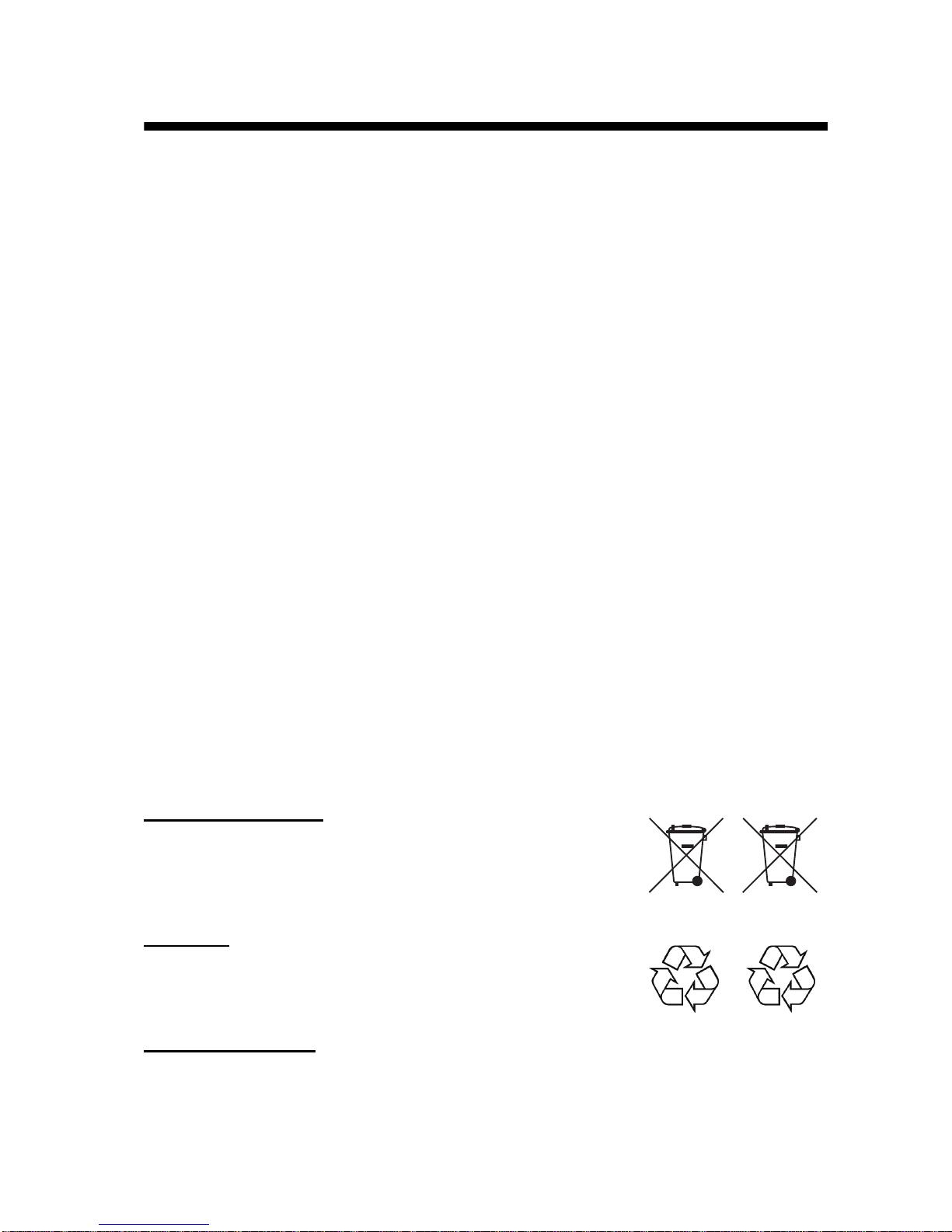
The crossed-out trash can symbol indicates that all types of batteries
must not be discarded in standard trash, or at a trash site. Take the
used batteries to a battery collection site according to your national
legislation and the Batteries Directive 2006/66/EU.
In the USA
The Mobius loop symbol (three chasing arrows) indicates that Ni-Cd
and lead-acid rechargeable batteries must be recycled. Take the used
batteries to a battery collection site according to local laws.
In the other countries
There are no international standards for the battery recycle symbol. The number of symbols can
increase when the other countries make their own recycle symbols in the future.
Cd
Ni-Cd Pb
Page 4
SAFETY INSTRUCTIONS
ii
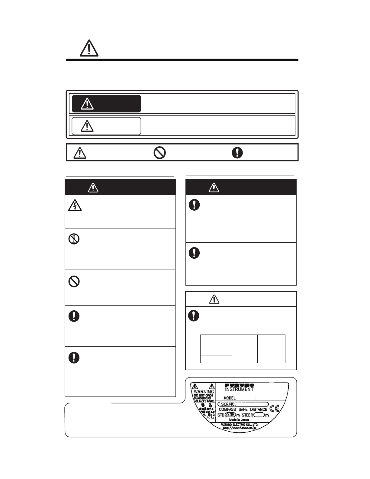
WARNING
Indicates a potentially hazardous situation which, if not
avoided, could result in death or serious injury.
CAUTION
Indicates a potentially hazardous situation which, if not
avoided, may result in minor or moderate injury.
Warning, Caution
Mandatory Action
Prohibitive Action
SAFETY INSTRUCTIONS
The operator of this equipment must read these safety instructions before attempting to
operate the equipment.
WARNING
Do not open the equipment.
Only qualified personnel should
work inside the equipment.
Do not disassemble or modify
the equipment.
Fire or electrical shock can result if
the equipment is modified.
Do not operate the equipment
with wet hands.
Electrical shock can result.
Safety instructions for the operator
Make sure no rain or water
splash leaks into the equipment.
Fire or electrical shock can result
if water leaks into the equipment.
Immediately turn off the power
at the switchboard if water leaks
into the equipment.
Continued use of the equipment
can cause fire or electrical shock.
Safety instructions for the installer
WARNING
Turn off the power at the switchboard before beginning the
installation.
Turn off the power to prevent
electrical shock.
Make sure the installation site is
not subject to water spray.
Fire or electrical shock can result if
water leaks into the equipment.
CAUTION
CAUTION
Observe the following compass
safe distances to prevent interference to the instruments:
Standard
compass
Steering
compass
0.35 m
FI-504
FI-507
Warning Label
A warning label is attached to the equipment. Do not
remove the label. If the label is missing or damaged,
contact a FURUNO agent or dealer about replacement.
0.30 m
0.25 m
Page 5

iii
TABLE OF CONTENTS
FOREWORD.............................................................................................. iv
SYSTEM CONFIGURATION ....................................................................... v
1.OPERATION............................................................................................. 1
1.1 Operating Controls, Display Layout......................................................................1
1.2 Turning the Power On/Off .................................................................................... 2
1.3 Adjusting Brilliance and Contrast ......................................................................... 2
1.4 Selecting a Display............................................................................................... 3
1.5 Selecting Apparent or True Wind Angle, Wind Speed.......................................... 8
1.6 Resetting Counters and Indications ..................................................................... 8
1.7 Alarms .................................................................................................................. 9
1.8 Timers ................................................................................................................11
2. MAINTENANCE, TROUBLESHOOTING .............................................. 13
2.1 Preventive Maintenance..................................................................................... 13
2.2 Troubleshooting.................................................................................................. 14
3. INSTALLATION..................................................................................... 15
3.1 Equipment Lists.................................................................................................. 15
3.2 Mounting.............................................................................................................16
3.3 Wiring ................................................................................................................. 18
3.4 Setting Up...........................................................................................................21
SPECIFICATIONS ................................................................................. SP-1
PACKING LIST........................................................................................ A-1
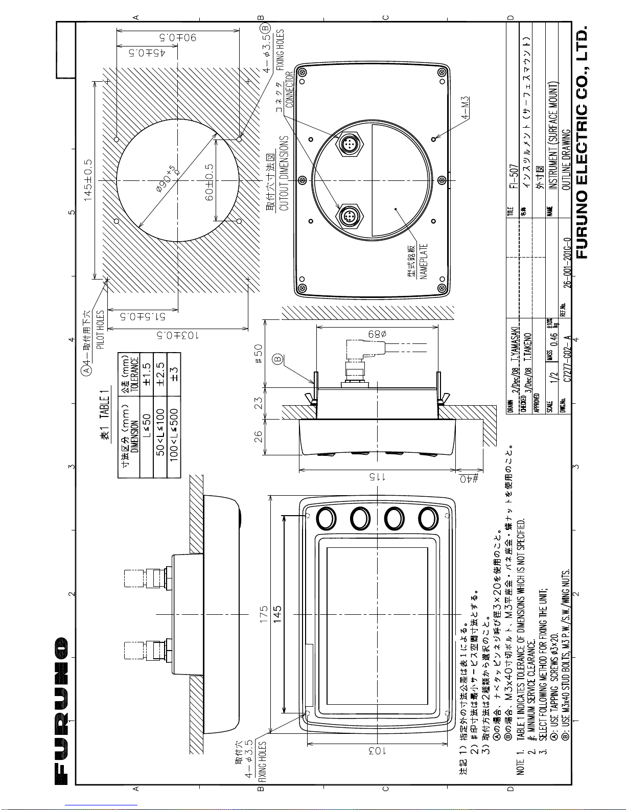
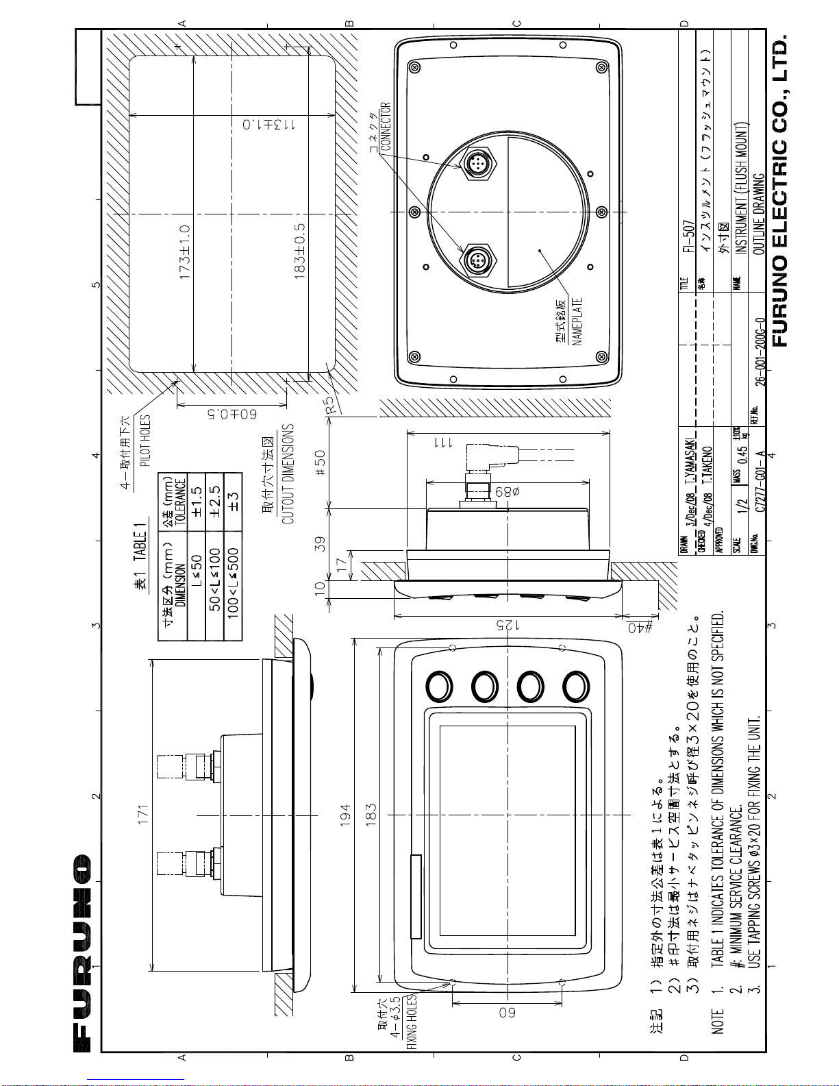
OUTLINE DRAWINGS............................................................................. D-1
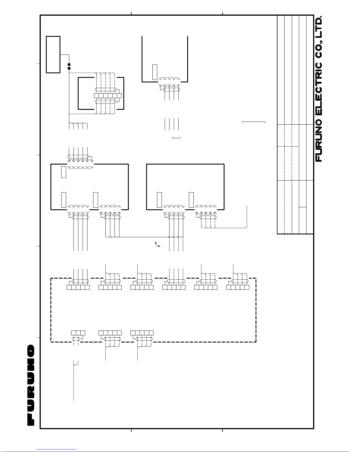
INTERCONNECTION DIAGRAM ............................................................ S-1
Page 6

iv
FOREWORD
A Word to the Owner of the FI-504, FI-507
Congratulations on your choice of the FURUNO FI-504 Multi/FI-507 Multi
XL displays, members of the FI-50 series of marine instruments. We are
confident you will see why the FURUNO name has become synonymous
with quality and reliability.
For over 60 years FURUNO Electric Company has enjoyed an enviable
reputation for quality marine electronics equipment. This dedication to
excellence is furthered by our extensive global network of agents and
dealers.
This equipment is designed and constructed to meet the rigorous demands of the marine environment. However, no machine can perform its
intended function unless operated and maintained properly. Please carefully read and follow the recommended procedures for operation and
maintenance.
Thank you for considering and purchasing FURUNO equipment.
Features
The FI-504 Multi/FI-507 Multi XL displays provide heading, environment,
autopilot, engine, depth, speed, and wind information, all on a high quality, backlit LCD. The sturdy weather-proof case is built to stand up to
even the harshest of environments.
The main features are
• Eight varieties of displays: heading, environment, autopilot, engine,
depth, speed, timer, and wind.
• Four levels of backlighting including off.
• Timers: Stopwatch and count-down
• Depth alarms: Shallow alarm, Deep alarm
• Anchor alarms: Shallow alarm, Deep alarm
• Voltage alarm monitors power source voltage
• Wind alarms: High apparent wind angle, Low apparent wind angle,
Max. true wind speed, Low true wind speed
• Speed indications: Max. STW, Average STW, SOG, Max. SOG, Average SOG, Wind speed, Max. true wind speed
• Log indication from 0 to 99,999 nm
• Resettable trip counter, from 0 to 999 nm
Page 7
v
SYSTEM CONFIGURATION
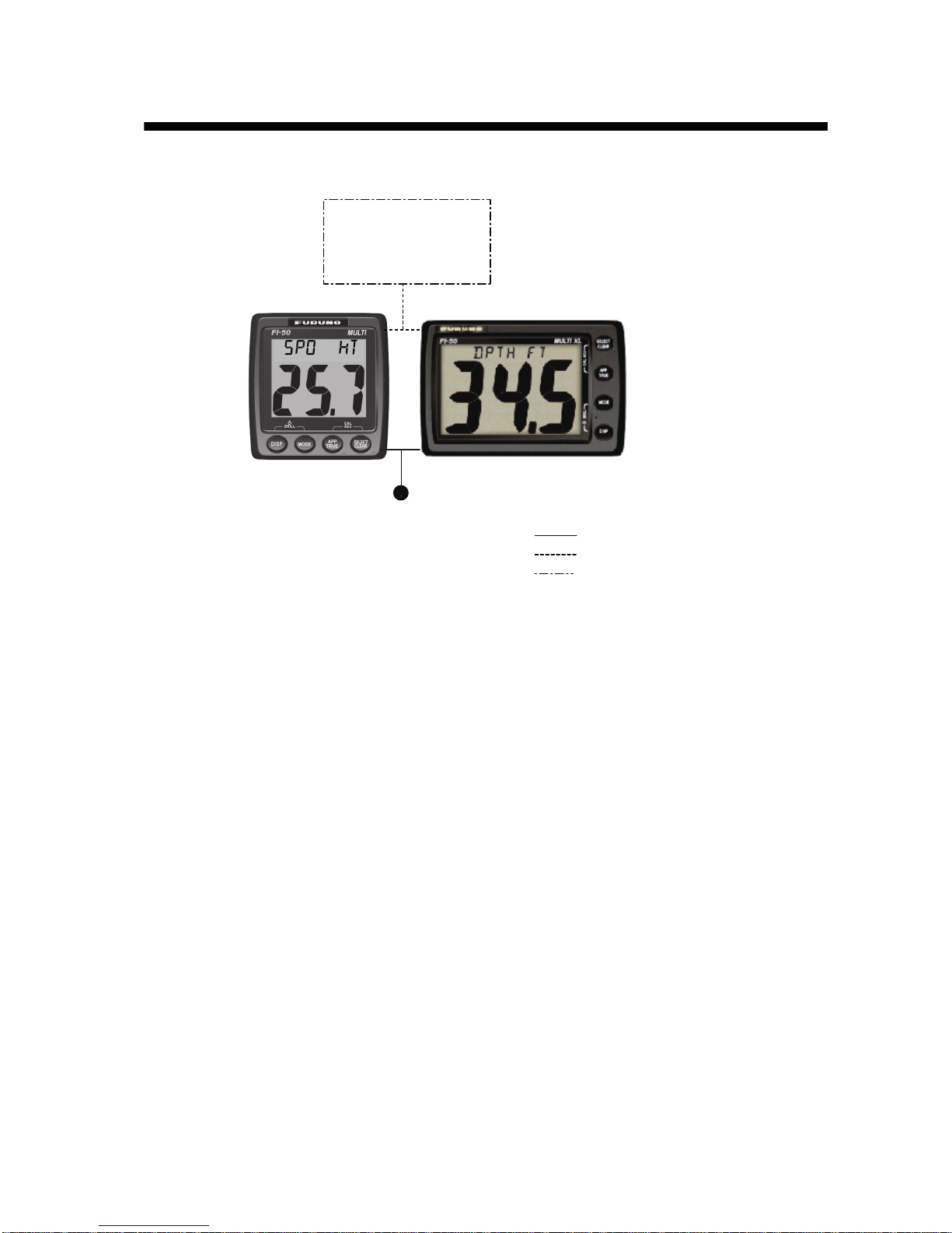
Standalone configuration
NOTICE: Turn on the terminal resistor in the instrument when connecting
an NMEA 2000 sensor or CAN bus device. For the procedure, see the
section on setting up, in the installation chapter.
: Standard Supply
: Optional Supply
: Local Supply
12 VDC
CAN bus Device
or
NMEA 2000 Sensor
(ex. Smart Sensor)
FI-504
FI-507
Page 8
SYSTEM CONFIGURATION
vi
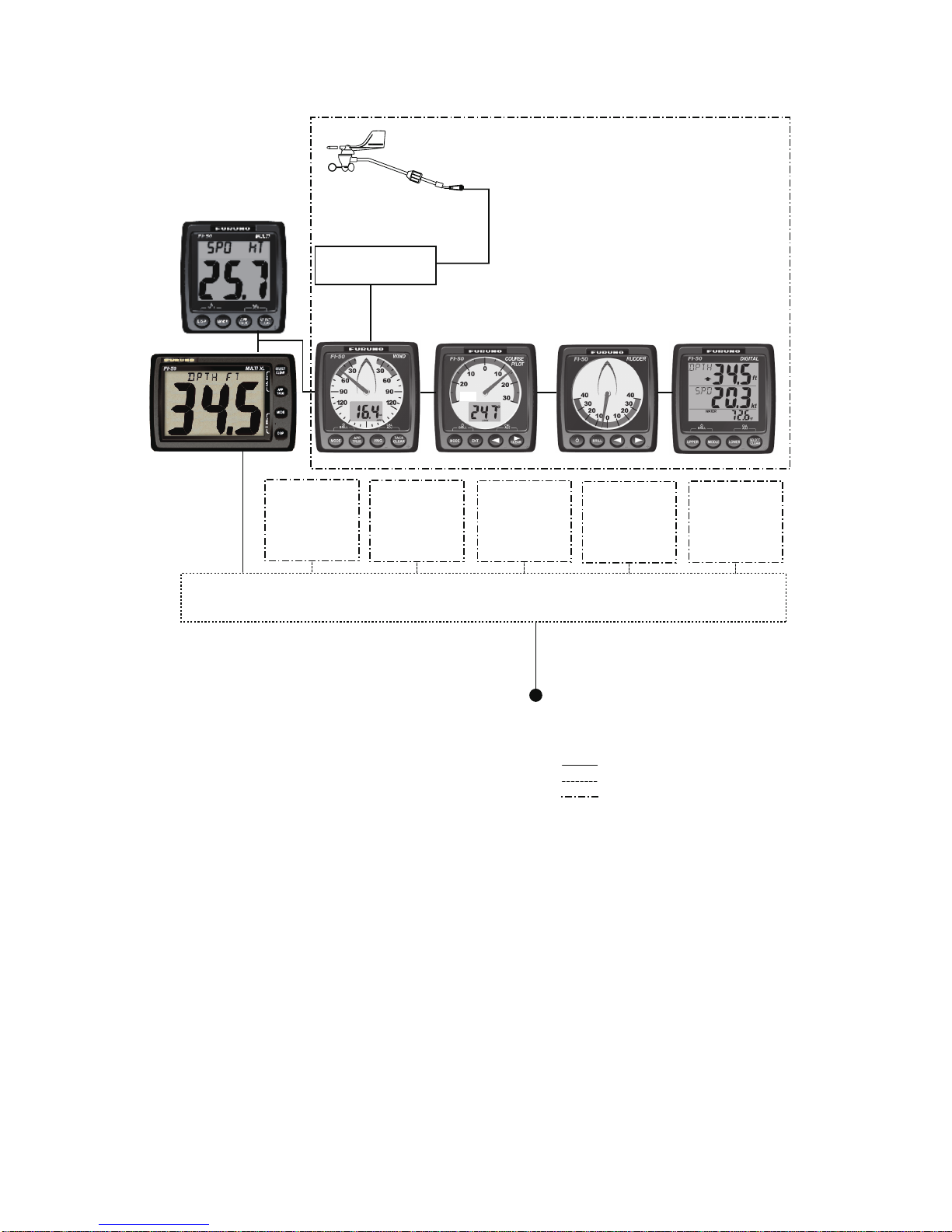
CAN bus network
NOTICE: Turn on the terminal resistor in the terminator of the CAN bus
network.
FI-501*
and/or
FI-502
FI-5001 or
FI-5001L
WIND
TRANSDUCER
TERMINAL BOX
(where necessary)
FI-503
DIGITAL
FI-504 MULTI
FI-505
COURSE PILOT
FI-506
RUDDER
30
: Standard Supply
: Optional Supply
: Local Supply
*FI-501 Wind Angle
FI-502 Close Hauled Wind Angle
JUNCTION BOX
FI-5002
* NMEA 2000 SENSORS
- Boat speed
- Depth
- Heading
- Navigation
- Environment
- Autopilot
- Engine
12 VDC
(not necessary if powered
by CAN bus network)
CAN bus
Device
or
NMEA 2000
SENSOR*
CAN bus
Device
or
NMEA 2000
SENSOR*
CAN bus
Device
or
NMEA 2000
SENSOR*
CAN bus
Device
or
NMEA 2000
SENSOR*
CAN bus
Device
or
NMEA 2000
SENSOR*
FI-507 MULTI XL
Page 9
1
1. OPERATION
Provided applicable sensors are connected, the FI-504/FI-507 provides
the following information, all on a backlit LCD:
• Depth
• Speed
• Heading
• Environment data
• Autopilot (rudder)
•Engine
•Wind
•Timers
• Navigation data
1.1 Operating Controls, Display Layout
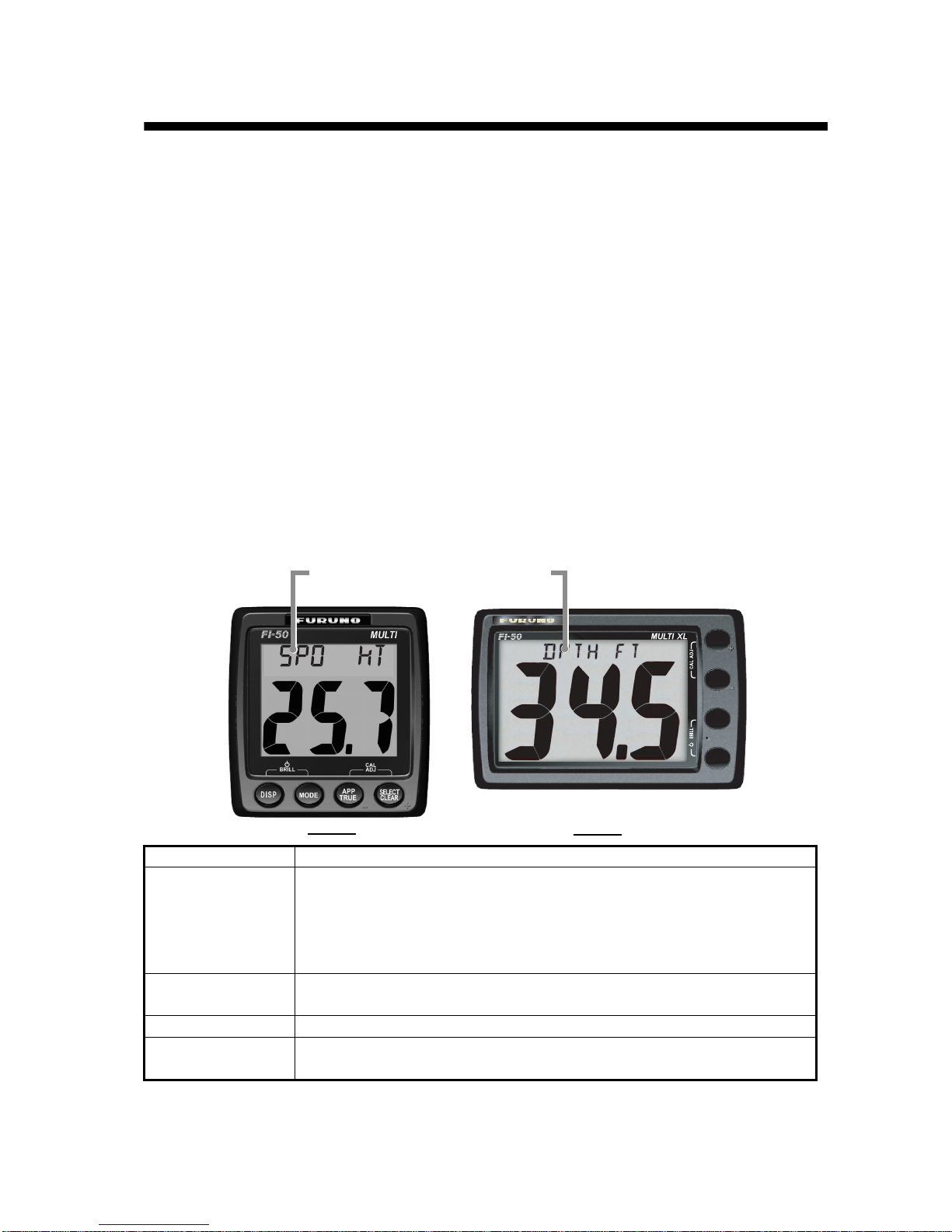
Note: The example screens shown in this manual are taken from the FI-
504. The screens from the FI-507 may be different.
Key name Function
SELECT/CLEAR
• Select menu option.
• Silence alarm.
• Clear data.
• Reset counters and indications.
• Increment value.
APP/TRUE
• Select apaprent or true (wind) alternately.
• Decrement value.
MODE Select a display.
DISP key
• Turn on power.
• Select a display category.
DISP
MODE
APP
TRUE
SELECT
CLEAR
FI-507
Mode name
(Ex. SPD=Speed, DPTH=Depth)
FI-504
Page 10
1. OPERATION
2
1.2 Turning the Power On/Off
To power the instrument, press the DISP key. All LCD segments go on
and off and then the last-used display appears.
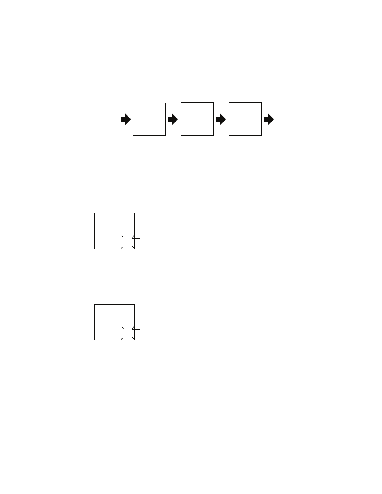
To power off the instrument, press the DISP and MODE keys together
(about 7-10 seconds). The timer appears and counts down from three
seconds to one second, and then the power goes off.
Power OFF sequence
1.3 Adjusting Brilliance and Contrast
1. Press the DISP and MODE keys together. The display for adjustment
of brilliance appears, with current brilliance setting flashing.
2. Within seven seconds of completing step 1, press the APP/TRUE key
to lower the brilliance, or the SELECT/CLEAR key to raise it.
3. Press the DISP and MODE keys together. The display for adjustment
of contrast appears, with current contrast setting flashing.
4. Within seven seconds of completing step 3, press the APP/TRUE key
to lower the contrast, or the SELECT/CLEAR key to raise it.
5. Press the DISP and MODE keys together to save the settings and
restore normal operation.
The brilliance and contrast will be the same on all units which are synchronized. (For how to synchronize units, see page 26.)
POWE
R
OFF
Press DISP
and MODE
keys together
3
POWER
2 1
POWER POWER
Brilliance setting (flashing)
2
BRILL
Contrast setting (flashing)
3
CONT
Page 11
1. OPERATION
3
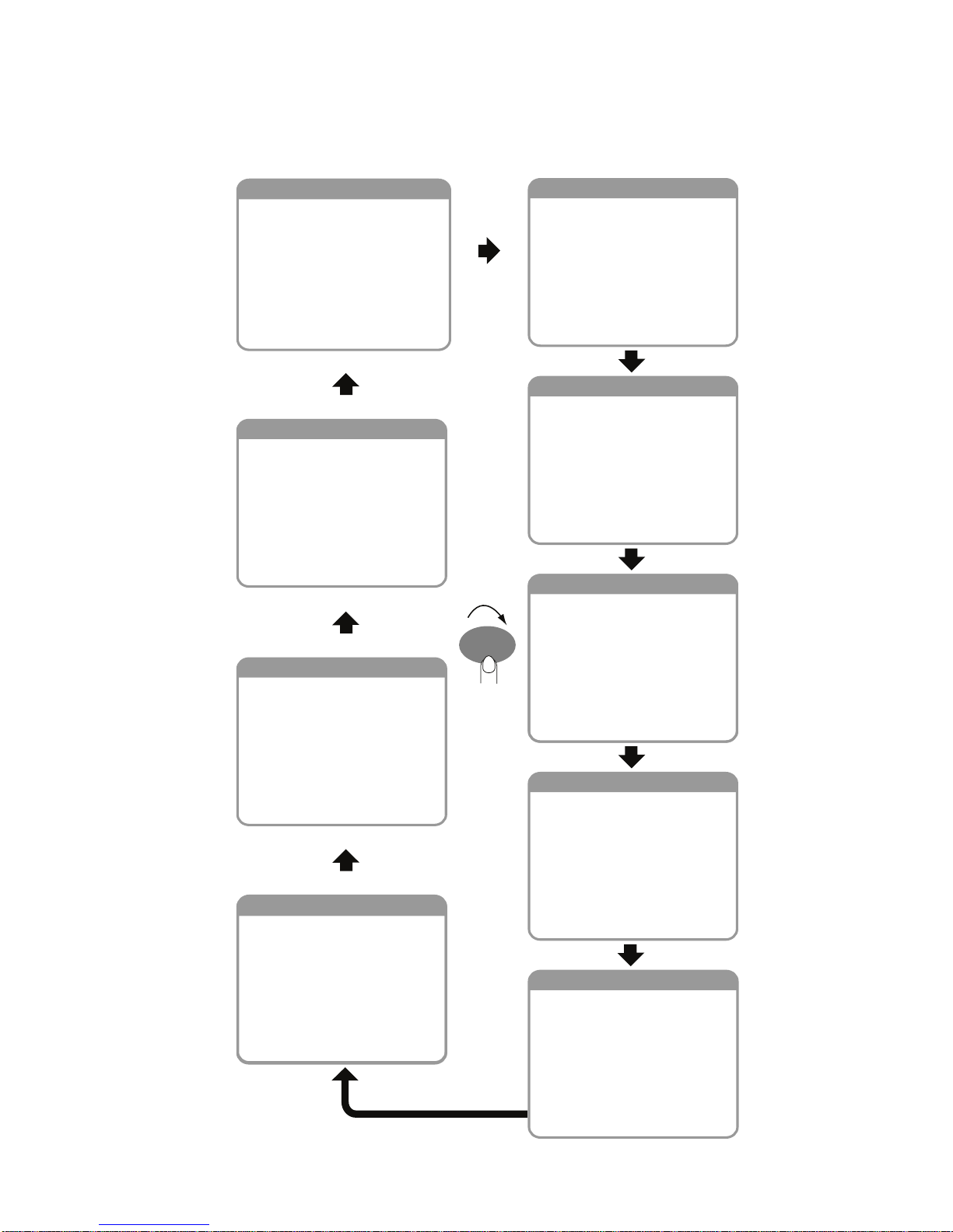
1.4 Selecting a Display
Use the DISP key to select a display category. Select desired display
with the MODE key.
HEADING
Current heading
Average heading
Heading on next tack
Course over ground
Course made good
Distance made good
NAVIGATION
Bearing to waypoint
Distance to waypoint
Cross track error
Waypoint number/name
Latitude
Longitude
Course over ground
Speed over ground
Satellites tracked
Roll
Pitch
AUTOPILOT
Rudder angle
ENGINE
Trip fuel usage
Fuel usage rate
Engine RPM
SPEED
Boat speed
Maximum STW
Average STW
SOG
Maximum SOG
Average SOG
VMG to windward
Log
Tr i p
TIMER
Count-up timer
Count-down timer 1
Count-down timer 2
DEPTH
Current depth
Shallow alarm
Deep alarm
Shallow anchor alarm
Deep anchor alarm
WIND
Wind speed
Maximum true wind speed
Maximum true wind speed alarm
Low true wind speed alarm
Wind angle
High apparent wind angle alarm
Low apparent wind angle alarm
Beaufort wind speed
Ground wind direction
ENVIRONMENT
Battery voltage
Minimum battery voltage alarm
Time
Date
Water temperature
Air temperature
Air pressure
Humidity
Wind chill temperature
Dew point
DISP
Page 12
1. OPERATION
4
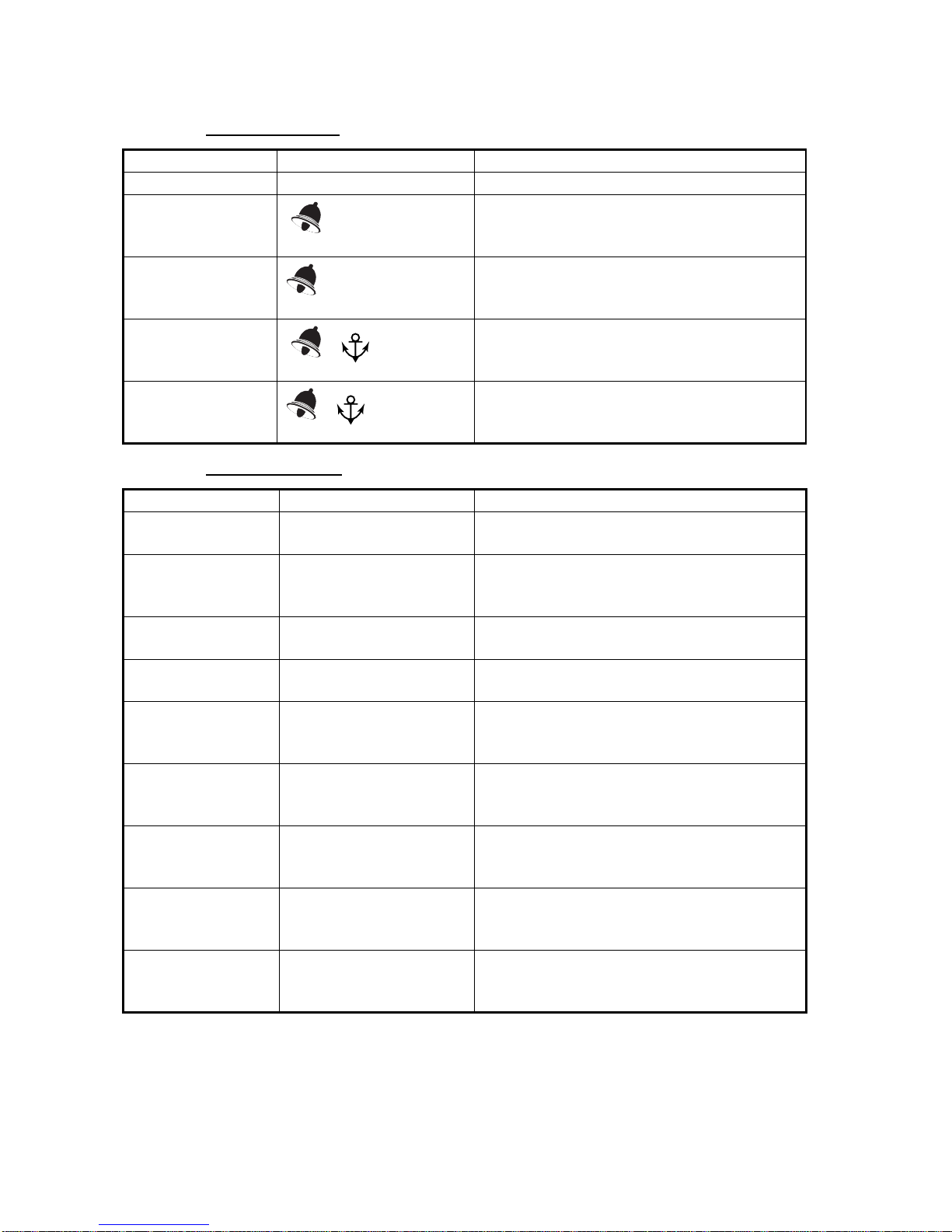
1.4.1 Display description
Depth category
Speed category
Display title Indication Function
Current depth DPTH Current depth, in meters, feet or fathoms.
Shallow alarm
SHALLOW
Set shallow depth alarm. Audio and visual
alarms are released when the depth is
lower than the threshold value.
Deep alarm
DEEP
Set deep depth alarm. Audio and visual
alarms are released when the depth is
higher than the threshold value.
Shallow anchor
alarm
SHALLOW
Set shallow anchor alarm. Audio and visual
alarms are released when the depth is
lower than the threshold value.
Deep anchor
alarm
DEEP
Set deep anchor alarm. Audio and visual
alarms are released when the depth is
higher than the threshold value.
Display title Indication Function
Boat speed SPD Boat speed, in knots (kt), miles per hour
(MPH) or kilometers per hour (KMH).
Maximum STW MAX SPD Maximum boat speed, in knots (kt), miles
per hour (MPH) or kilometers per hour
(KMH).
Average STW AVG SPD Average boat speed, in knots (kt), miles per
hour (MPH) or kilometers per hour (KMH).
SOG SOG Speed over ground, in knots (kt), miles per
hour (MPH) or kilometers per hour (KMH).
Maximum SOG MAX SOG Maximum speed over ground, in knots (kt),
miles per hour (MPH) or kilometers per
hour (KMH).
Average SOG AVG SOG Average speed over ground, in knots (kt),
miles per hour (MPH) or kilometers per
hour (KMH).
VMG to windward VMG Velocity made good to windward, in knots
(kt), miles per hour (MPH) or kilometers per
hour (KMH).
Log LOG Log distance (total distance run), in nautical
miles, (NM) kilometers (KM) or statute
miles (SM).
Trip TRIP Trip distance (distance run between two
points), in nautical miles (NM), kilometers
(KM) or statute miles (SM).
Page 13
1. OPERATION
5
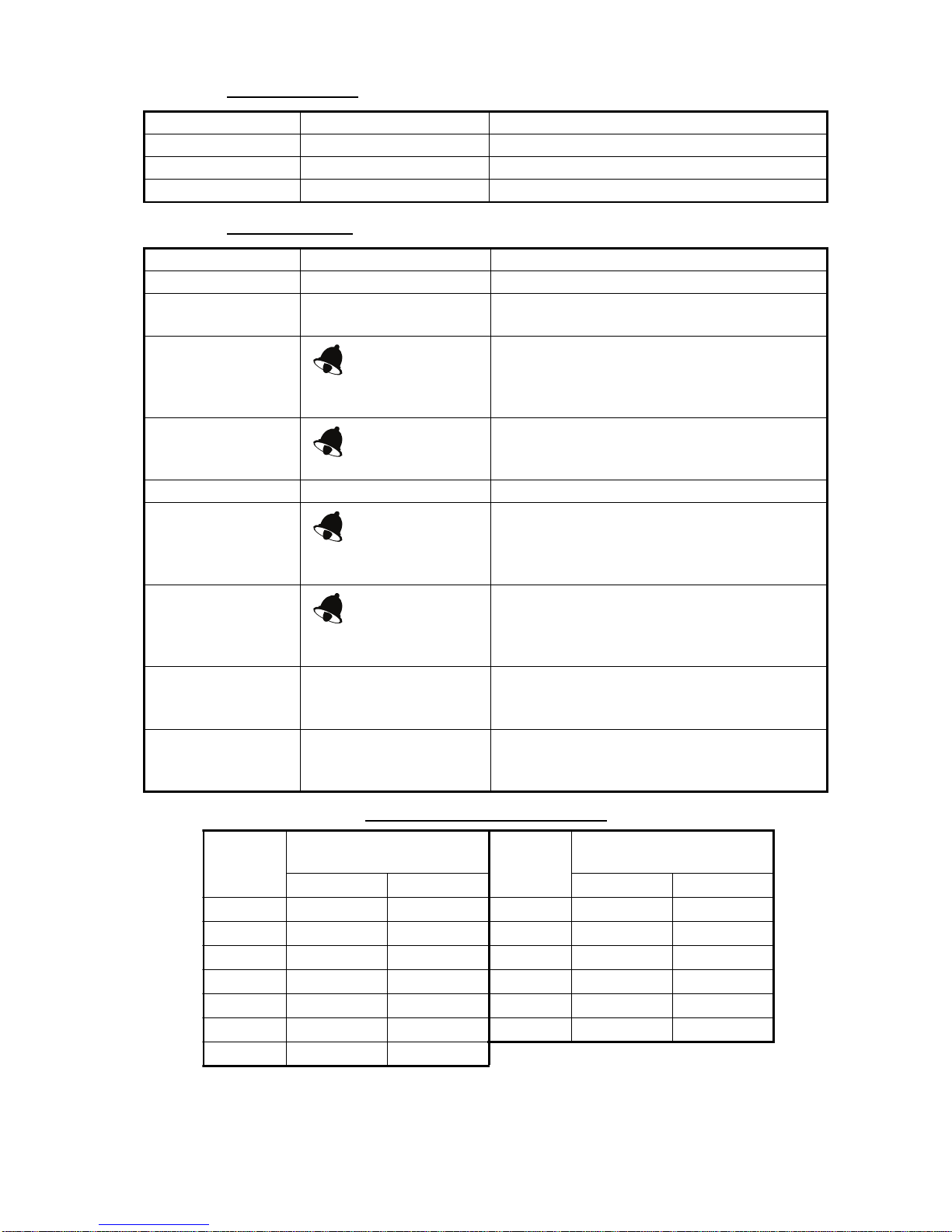
Timer category
Wind category
Beaufort no. and wind speed
Display title Indication Function
Count up timer UP Count-up timer.
Count down timer 1 DOWN 1 Count-down timer 1.
Count down timer DOWN 2 Count-down timer 2.
Display title Indication Function
Wind speed APP (or TRUE) Wind speed, in knots or meters/second.
Maximum true wind
speed
MAX TRUE Maximum true wind speed.
Maximum true wind
speed alarm
MAX TRUE
Set maximum true wind speed alarm. Audio
and visual alarms are released when the
wind speed goes higher than the threshold
value.
Low true wind
speed alarm
TRUE LO
Set low true wind speed alarm. Audio and
visual alarms are released when the wind
speed goes lower than the threshold value.
Wind angle APP (or TRUE) Apparent (or true) wind angle, in degrees.
High apparent wind
angle alarm
APP HI
Set high apparent wind angle alarm. Audio
and visual alarms are released when the
wind angle at starboard goes higher than
the threshold value.
Low apparent wind
angle alarm
APP LO
Set low apparent wind angle alarm. Audio
and visual alarms are released when the
wind angle at port goes lower than the
threshold value.
Beaufort wind
speed
BFT Beaufort wind speed. Beaufort speeds up to
12 are shown. See the table below for Beau-
fort no. and wind speed.
Ground wind angle GWIND Angle of wind over ground, in degrees.
Bearing reference in Magnetic (MAG) or
True (TRUE).
Beaufort
no.
Wind speed
Beaufort
no.
Wind speed
kt m/s kt m/s
0 0 0-0.2 7 28-33 14.4-17.4
1 1-3 0.5-2.0 8 34-40 17.5-21.0
2 4-6 2.1-3.5 9 41-47 21.1-24.6
3 7-10 3.6-5.6 10 48-55 24.7-28.8
4 11-16 5.7-8.6 11 56-63 28.9-32.6
5 17-21 8.7-11.2 12 64 32.7-32.9
6 22-27 11.3-14.3
Page 14
1. OPERATION
6
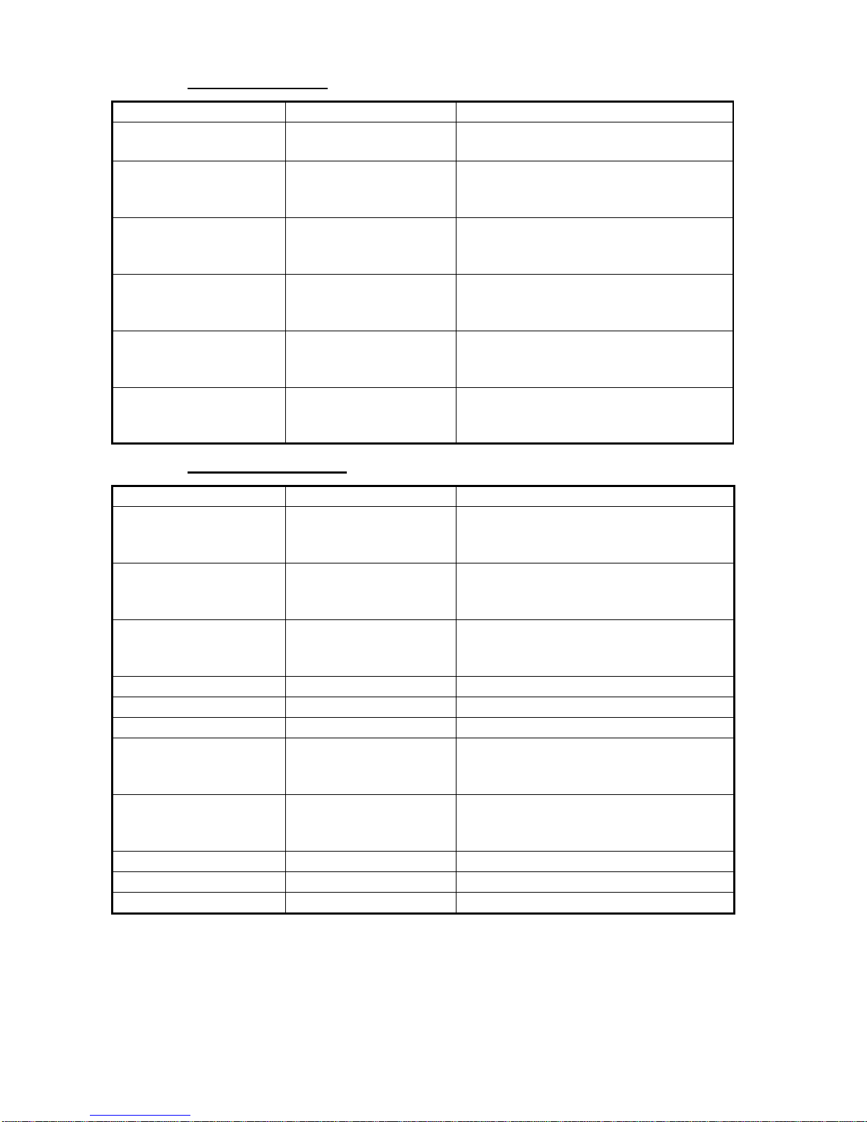
Heading category
Navigation category
Display title Indication Function
Current heading HDG Heading, in degrees. Bearing reference
in Magnetic (MAG) or True (TRUE).
Average heading AVG HDG Average heading, in degrees. Bearing
reference in Magnetic (MAG) or True
(TRUE).
Heading on next tack TACK Heading on next tack, in degrees true
(fixed). Bearing reference in Magnetic
(MAG) or True (TRUE).
Course over ground COG Course over ground, in degrees. Bear-
ing reference in Magnetic (MAG) or
True (TRUE).
Course made good CMG Course made good, in degrees. Bearing
reference in Magnetic (MAG) or True
(TRUE).
Distance made good DMG Distance made good, in kilometers
(km), nautical miles (nm) or statute
miles (sm).
Display title Indication Function
Bearing to waypoint BTW Bearing to waypoint, in degrees.
Bearing reference of Magnetic (MAG) or
True (TRUE)
Distance to waypoint DTW Distance to waypoint, in kilometers
(KM), nautical miles (NM) or statute
miles (SM).
Cross track error XTE Cross-track error, in kilometers (KM),
nautical miles (NM) or statute miles
(SM).
Waypoint number/name WPT Waypoint number and name are shown.
Latitude LAT Position in latitude.
Longitude LON Position in longitude.
Course over ground COG Course over ground, in degrees.
Bearing reference in Magnetic (MAG) or
True (TRUE).
Speed over ground SOG Speed over ground, in knots (KT), miles
per hour (MPH) or kilometers per hour
(KMH).
Satellites tracked GPS SAT GPS satellites tracked.
Roll ROLL Ship’s roll, in degrees.
Pitch PITCH Ship’s pitch, in degrees.
Page 15
1. OPERATION
7
Environment category
Autopilot category
Engine category
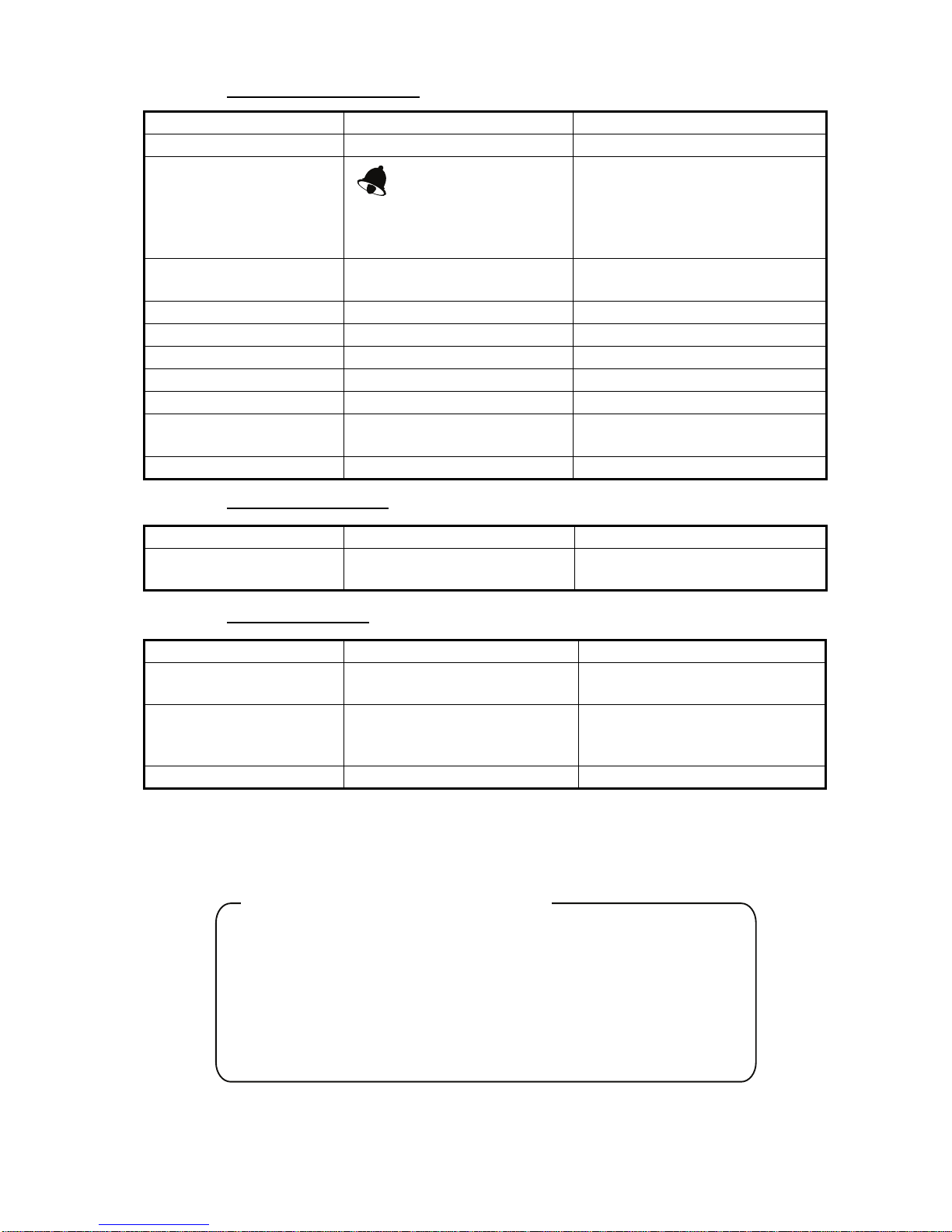
Note: In case of multiple engines, the data of desired engine number
(max. eight, E0-E7) can be selected with the SELECT/CLEAR key.
Display title Indication Function
Battery voltage VOLTS Battery voltage.
Minimum battery voltage
alarm
VOLTS LO
Set low battery voltage alarm.
Audio and visual alarms are
released when the battery
voltage goes lower than the
threshold value.
Time - Current time, in 12-hour or
24-hour format.
Date - Current date.
Water temperature WATER Water temperature, in
°C or °F.
Air temperature AIR Air temperature, in
°C or °F.
Air pressure PRE Air pressure, in Hectopascal.
Humidity HUMID Relative humidity, in percentage.
Wind chill temperature CHILL Wind chill temperature, in
°C or
°F.
Dew point DEW Dew point, in
°C or °F.
Display title Indication Function
Rudder angle
RUDDER Rudder angle, in degrees either
P(ort) or S(tarboard).
Display title Indication Function
Trip fuel used
TOTAL Total fuel consumption, in liters
or gallons.
Fuel rate
RTE (L/H) Amount of fuel consumed in
hour, in liters/hour (L/H) or
gallons/hour (G/H).
Engine RPM
RPM Engine speed per minute.
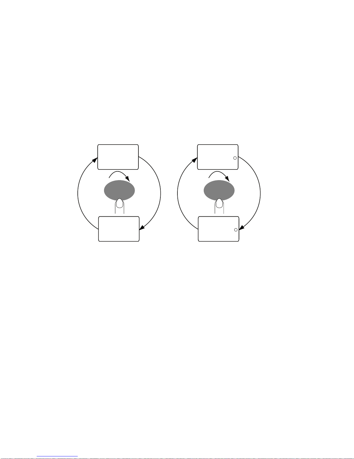
Display scrolling speed and direction can be changed by the length of
key push.
Short push: Scroll in forward order.
Medium push: Go back one display. Several beeps sound and then the
previous display appears.
Hold down: Rapid scrolling, in forward direction. Several beeps sound
and then speed is changed.
Scrolling speed and scrolling direction
Page 16
1. OPERATION
8
1.5 Selecting Apparent or True Wind Angle,
Wind Speed
You can show wind angle and wind speed in apparent or true wind. The
apparent wind is the actual flow of air acting upon a sail, or the wind as
it appears to the sailor. True wind is the wind seen by a stationary observer in velocity and direction.
WIth a wind angle or wind speed indication displayed, press the APP/
TRUE key to change the wind angle or wind speed to apparent and true
alternately. A beep sounds after the change is completed. (Wind angle
and wind speed displays are mutually changed.) True wind requires boat
speed input. If there is no speed input three dashes appear.
1.6 Resetting Counters and Indications
You can reset the following counters and indications:
•Trip
• Course made good
• Distance made good
• Average speed
• Average SOG
• Maximum speed
• Maximum SOG
• Average heading
• Maximum true wind speed
Select the applicable display and press and hold down the SELECT/
CLEAR key. A short beep sounds, the counter or indication flashes twice
and then a long beep sounds to indicate that resetting is completed.
HI
APP KT
5.0
HI
TRUE KT
APP
TRUE
Apparent and true
wind speeds
Apparent and true
wind angles
HI
APP
HI
TRUE
APP
TRUE
135
157
9.6
Page 17
1. OPERATION
9
1.7 Alarms
There nine conditions which trigger audio and visual alarms: Shallow
alarm, Deep alarm, Shallow anchor alarm, Deep anchor alarm, Max. true
wind speed alarm, Low true wind speed alarm, High apparent wind angle
alarm, low apparent wind angle alarm, and low battery voltage alarm.
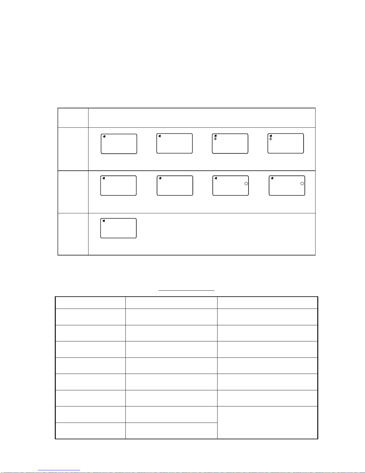
1. Use the DISP and MODE keys to select desired alarm page, referring
to the illustration below for alarm location.
.
Alarm description
Alarm Alarms released when; Setting range
Shallow alarm depth is shallower than this
threshold.
0.0-303 m
Deep alarm depth is deeper than this
threshold.
0.1-304 m
Shallow anchor alarm anchor depth is shallower than
this threshold.
depth is shallower than this
threshold.
Deep anchor alarm anchor depth is greater than
this threshold.
depth is deeper than this
threshold.
Max. true wind speed
alarm
max. true wind speed is
greater than this threshold.
0.1-999 kts
Low true wind speed
alarm
true wind speed is lower than
this threshold.
0-998 kts
High apparent wind
angle alarm
apparent wind angle is higher
than this threshold.
S0
°-S179° (High)
S180°-P1° (Low)
(S=Starboard, P=Port)
Low apparent wind
angle alarm
apparent wind angle is lower
than this threshold.
Display
category
DEPTH
WIND
Available alarms
SHALLOW
02
0
Shallow alarm
Deep alarm
DEEP
15
0
SHALLOW
5.0
Shallow anchor
alarm
Deep anchor
alarm
DEEP
10.
0
Max. true wind
speed alarm
TRUE KT
38.9
MAX
Low true wind
speed alarm
TRUE KT
9.7
LO
High apparent
wind angle alarm
APP S* HI
12.2
Low apparent
wind angle alarm
APP S* LO
5.4
ENVIRONMENT
Low voltage
alarm
VOLTS
9.0
LO
*S (Starboard) or P (Port)
Page 18
1. OPERATION
10
2. If the selected alarm page shows “Off,” press and hold down the
SELECT/CLEAR key until an alarm setting appears.
3. Press the APP/TRUE and SELECT/CLEAR keys together to enable
adjustment. The alarm setting starts flashing.
4. Press the APP/TRUE key to lower the setting; the SELECT/CLEAR
key to raise it.
Note: A low alarm cannot be set higher than its affiliated high (max.)
alarm.
5. Press the APP/TRUE and SELECT/CLEAR keys together to confirm
setting and restore normal operation.
When an alarm is violated, the buzzer sounds and the alarm icon ( )
flashes. You can silence the buzzer with the SELECT/CLEAR key. The
icon continues flashing until the offending alarm is disabled.
While the icon is flashing you can switch between alarm display and current display alternately by pressing the DISP and SELECT/CLEAR keys
together.
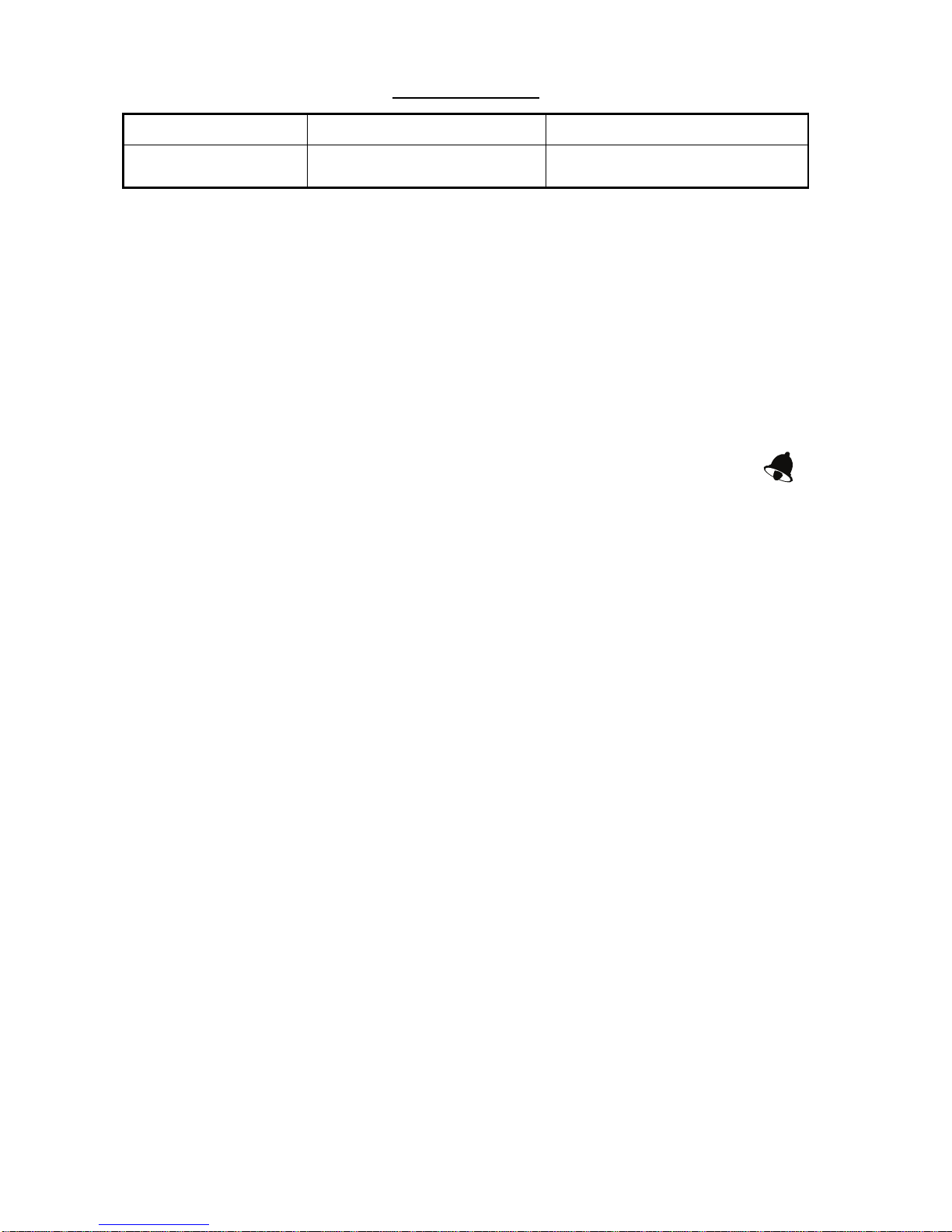
Low battery voltage
alarm
battery voltage is lower than
this threshold.
5.0 - 20.0 volts
Alarm description
Alarm Alarms released when; Setting range
Page 19

1. OPERATION
11
1.8 Timers
Three timers are provided:
• Count-up timer (stopwatch)
• Count-down timer (two provided)
Time is displayed in seconds or minutes, depending on counter values.
Once you have set a timer, you can leave that page and select any other
display. The counter continues to run in the background.
Count-up timer
The count-up timer functions like a stop watch, counting time upward, to
99 hours, 99 minutes and 59 seconds.
Count-down timers
The two count-down timers count down from a time between 15 minutes
and one minute. When these timers have counted down to zero, they
then start counting up. The timers beep at preset intervals to alert you to
specific points in time.
• Two beeps every minute
• Three beeps at the start of the last 30 seconds
• One beep/second for each of the last 10 seconds
• Two-second beep at zero
How to set the timers
1. Press the MODE key to show the desired timer display.
2. Do one of the following depending on timer type selected:
Count-up timer:
Press the SELECT/CLEAR key to start the timer. A long beep sounds
and the timer starts counting upward.
Count-down timer:
To start the timer from the time shown, press the SELECT/CLEAR
key. To set a different start time, press the APP/TRUE and SELECT/
CLEAR keys together to enable adjustment. Use the APP/TRUE key
to lower the value; SELECT/CLEAR key to raise it. Press the APP/
TRUE and SELECT/CLEAR keys together to confirm setting. Press
the SELECT/CLEAR key to start the timer.
Count-up
timer
00:00:00.0
UP
Count-down
timer 1
DOWN 1
15.0
Count-down
timer 2
DOWN 2
15.0
Page 20

1. OPERATION
12
To stop or restart the timer, press the SELECT/CLEAR key momen-
tarily. A short beep sounds when the timer is stopped or restarted.
To stop and reset the timer to start value, press the SELECT/CLEAR
key until you hear a long beep. The timer is stopped and reset to start
value.
The timer settings are reflected on any timer-equipped instrument in the
network which is set up for synchronization.
Page 21
13
2. MAINTENANCE,
TROUBLESHOOTING
This chapter provides the information necessary for keeping your equipment in good working order.
2.1 Preventive Maintenance
Following the recommended procedures below will help maintain performance.
Check item Check point Remedy
Cabling Check that all cabling is
securely fastened and is
free or rust and corrosion.
Reconnect if necessary. Replace if damaged.
Cabinet Dust on cabinet Remove dust with a soft, lint-free cloth.
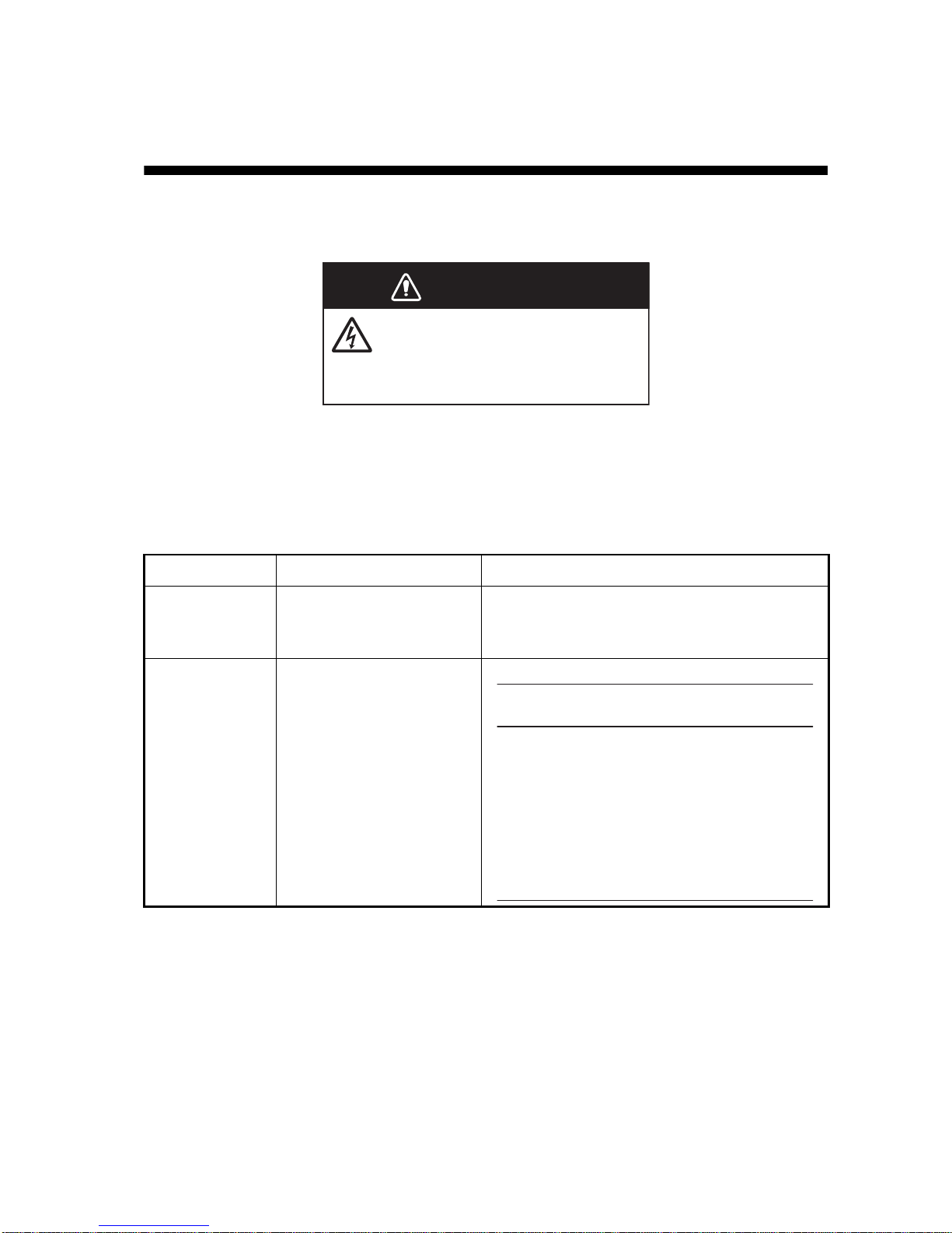
WARNING
Do not open the equipment.
Only qualified personnel should
work inside the equipment.
NOTICE
Do not apply paint, anti-corrosive
sealant or contact spray to coating
or plastic parts of the equipment.
Those items contain organic solvents
that can damage coating and plastic
parts, especially plastic connectors.
Page 22

2. MAINTENANCE, TROUBLESHOOTING
14
2.2 Troubleshooting
If you feel the equipment is not functioning properly, follow the procedures in the table below to try to restore normal operation. If normal operation cannot be restored, do not attempt to check inside the cabinet.
There are no user-serviceable parts inside.
Troubleshooting
Problem Possible cause Remedy
Display is
blank. Panel is
not lit.
• Power supply
• Cabling disconnected or
damaged.
• Check power supply.
• Check cabling.
Power is on but
no or some
data.
Sensor is turned off.
Cable from sensor is disconnected
or damaged.
• Turn on sensor.
• Check cabling.
Inaccurate data • Electromagnetic field generating
equipment is in operation.
• Cabling from sensor is damaged.
• Sensor is improperly aligned
(where applicable).
• Turn off all electromagnetic field
generating equipment. Turn them on
and off one by one. Check the display. Relocate offending equipment
or this instrument as appropriate.
• Check cabling.
• Check installation. If installation is
proper, an offset may be applied to
certain data. For details, see section
1.7.
Page 23
15
3. INSTALLATION
3.1 Equipment Lists
Standard supply
(FI-504)
(FI-507)
Optional supply
Name Type Code No. Qty Remarks
Display Unit FI-504 - 1
Installation
Materials
CP26-00600 000-011-744 1 set See packing list at end of
manual for details.
Name Type Code No. Qty Remarks
Display Unit FI-507 - 1
Installation
Materials
CP26-00800 000-015-730 1 set See packing list at end of
manual for details.
Name Type Code No. Qty Remarks
Cable Assy. FI-50-DROP-6M 001-105-810-10 1
FI-50-CHAIN-0.3M 001-105-820-10 1
FI-50-CHAIN-5M 001-105-840-10 1
FI-50-CHAIN-1M 000-166-950-11 1
FI-50-CHAIN-10M 001-105-850-10 1
FI-50-CHAIN-20M 001-105-860-10 1
Flush Mount Kit FI-50-FLUSH-KIT 000-010-619 1 set For FI-504
FI-507-FLUSH-KIT 000-015-722 For FI-507
Junction Box FI-5002 000-010-765 1 set
Smart Sensor DST-800 000-168-850-10 1
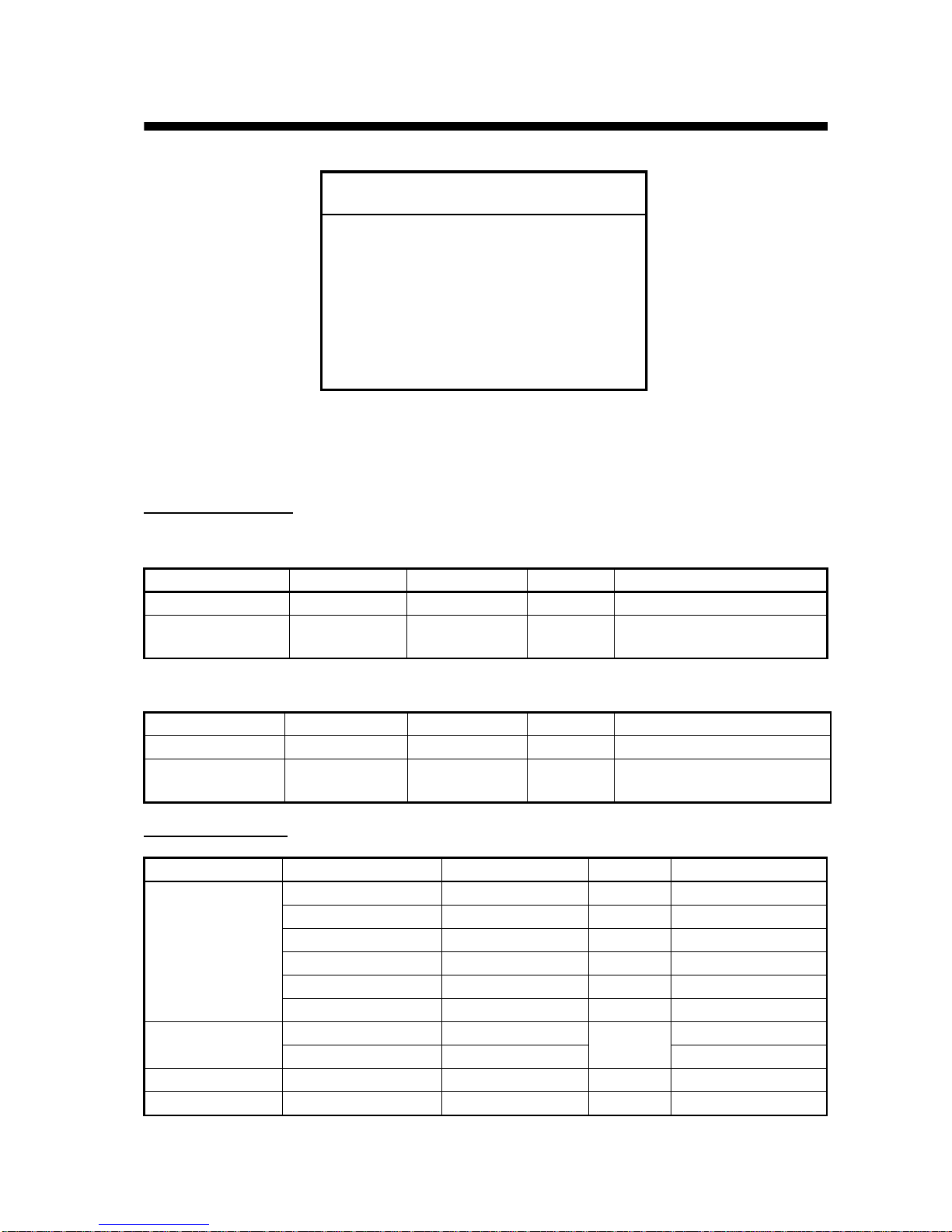
NOTICE
Do not apply paint, anti-corrosive
sealant or contact spray to coating
or plastic parts of the equipment.
Those items contain organic solvents
that can damage coating and plastic
parts, especially plastic connectors.
Page 24
3. INSTALLATION
16
3.2 Mounting
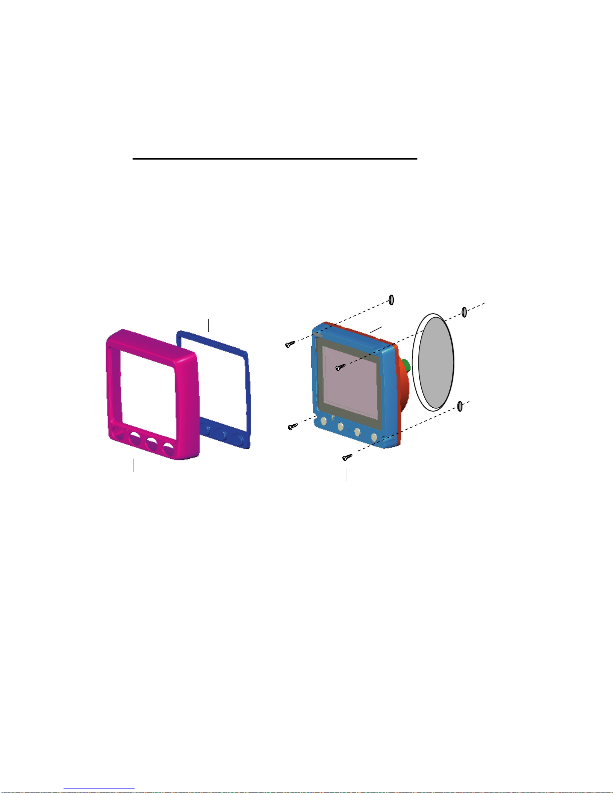
The display unit can be installed two ways: surface mount (fixed at front
panel or fixed from rear panel) and flush mount (optional kit required).
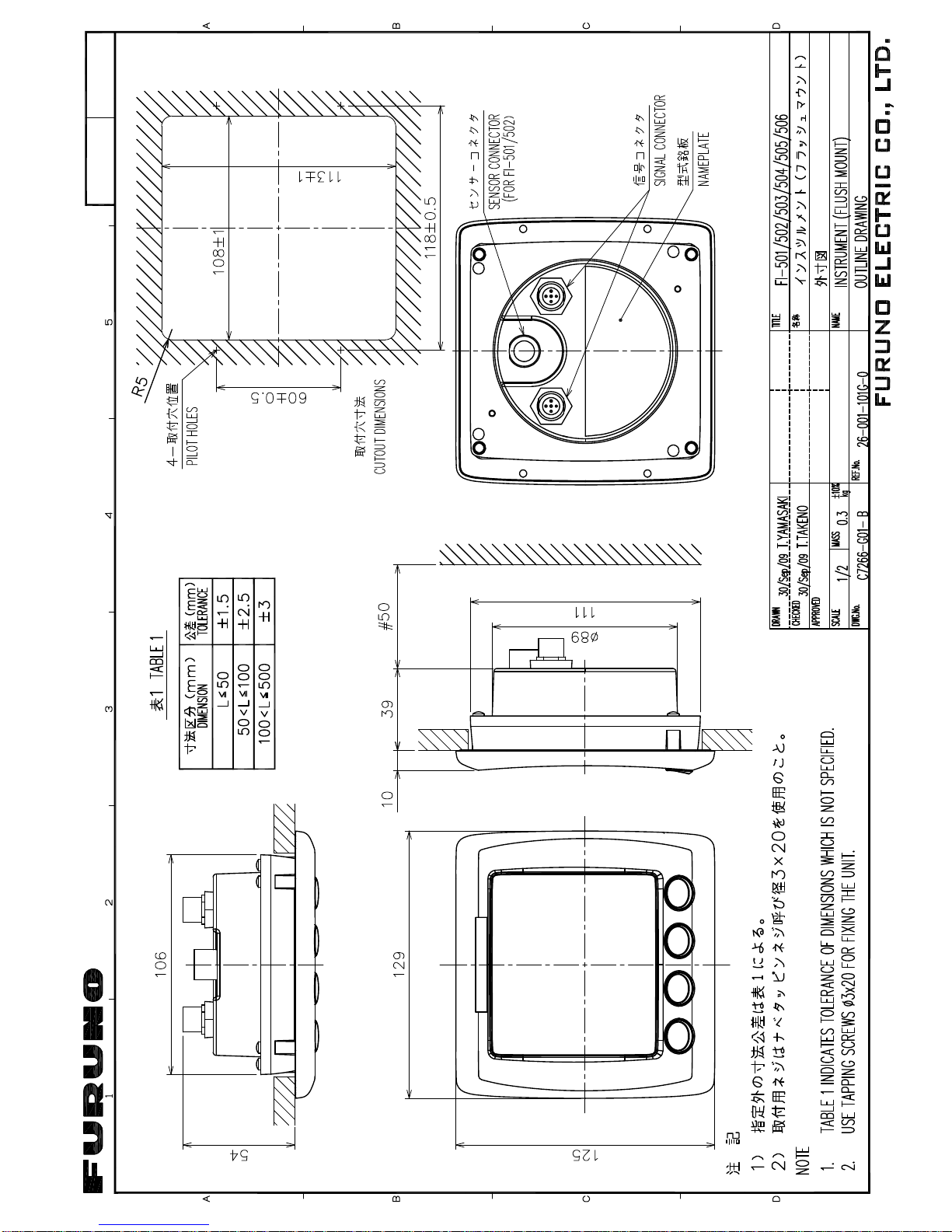
This section covers surface mounting. For flush mounting, see the flush
mounting instructions, issued separately.
Surface mount 1: Fix instrument from front panel
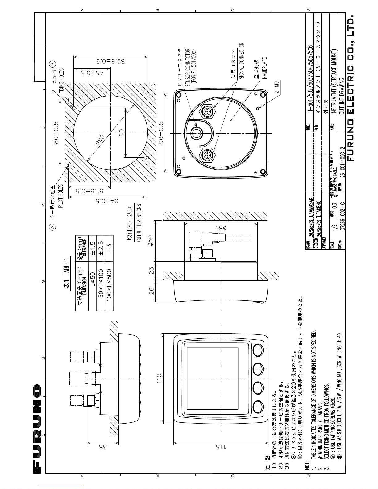
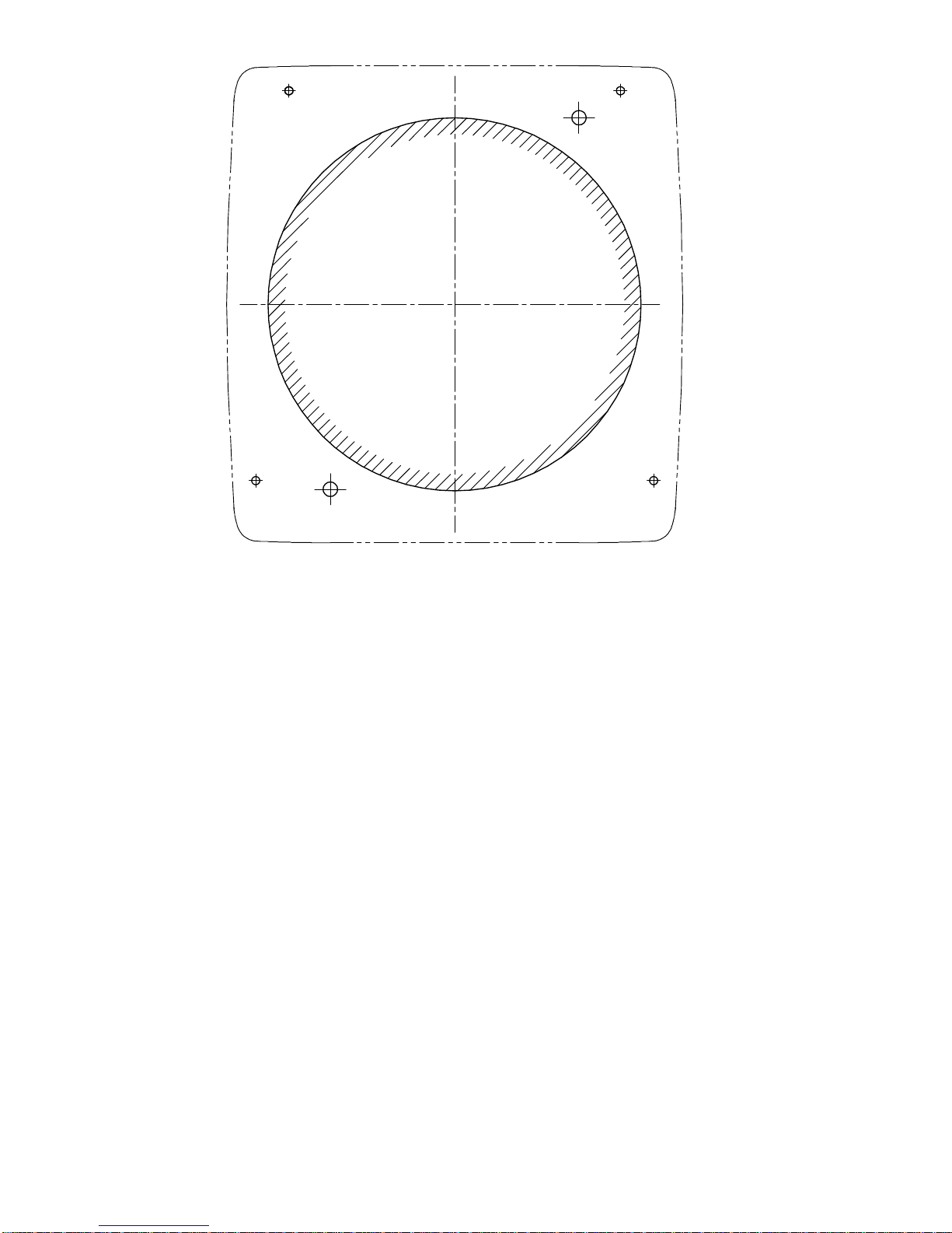
1. Using the applicable template at the back of this manual, open a
mounting hole in the installation site.
2. Detach the front panel together with the keypad assy. Attach sponge
(supplied) to rear of display unit.
3. Set the display unit to the mounting hole, and fix it with four self-tapping screws (3×20, supplied).
4. Attach the front panel and keypad assy. to the display unit.
Self-tapping screw (3x20)
Mounting
Hole
Front Panel
Keypad Assy.
Sponge
(ex. FI-504)
Page 25
3. INSTALLATION
17
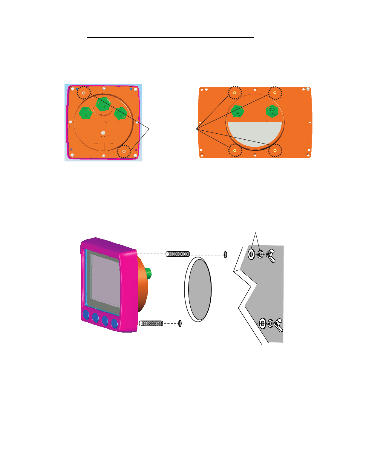
Surface mount 2: Fix instrument from rear panel
1. Using the applicable template at the back of this manual, open a
mounting hole in the installation site.
2. Insert studs (M3×40, 2 pcs. (FI-504) or 4 pcs. (FI-507), supplied) in
the holes shown below. (Use only the studs supplied.)
3. Set the display unit to the mounting hole, inserting studs through
respective holes. Fix the display unit with spring washers, flat washers and wing nuts (M3, supplied).
Insert stud here.
(FI-504)
(FI-507)
Display unit, rear view
Stud (M3x40)
Wing Nut (M3)
Mounting
Hole
(ex. FI-504)
Flat Washer and
Spring Washer (M3)
Page 26
3. INSTALLATION
18
3.3 Wiring
For the service technician detailed information about CAN bus wiring is
on the FURUNO Tech-net. See “Furuno CAN bus Network Design
Guide” (TIE-00170-*).
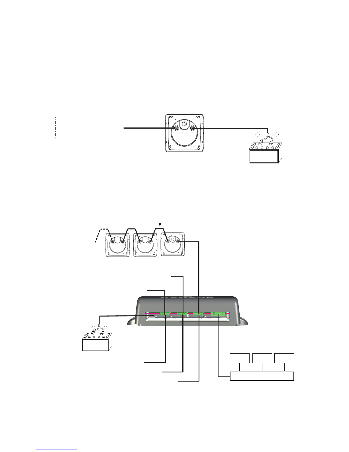
3.3.1 Standalone configuration
For standalone configuration the junction box is not necessary; connect
the instrument directly to the power supply.
3.3.2 Multi-instrument configuration
FI-50-DROP-6M
Cable (6 m)
Display Unit
FI-504/507
(507 not shown)
Red
Black
+
–
12 VDC
CAN bus Device
or
NMEA 2000 Sensor
CAN bus
drop cable
FI-50-DROP-6M Cable
(6 m, standard supply)
Red
Black
+
–
DISP. UNIT
FI-504/507
(507 not shown)
DISP. UNIT
FI-501/502/FI-503/FI-505/FI-506
(Instruments can be connected
in any order.)
FI-50-CHAIN
(0.3 m: Std, 1/5/10/20 m: Option)
Power Cable (2 m)
CAN bus
Backbone Cable
(local supply)
NOTE: The total length of drop cables and backbone cables must be within 80 m.
JUNCTION BOX
FI-5002
(optional supply)
Instruments chained
as above
Instruments chained
as above
Instruments chained as above
Instruments chained as above
Instruments chained as above
JUNCTION BOX FI-5002
FI-50X FI-50XFI-50X
Page 27
3. INSTALLATION
19
Junction box (option)
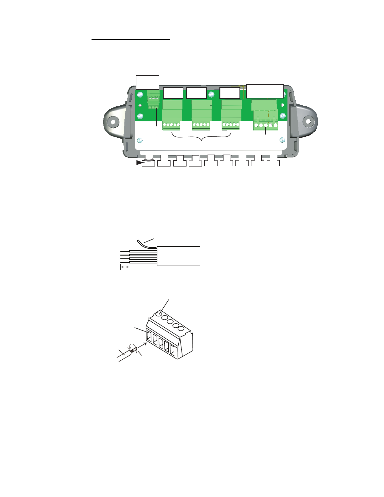
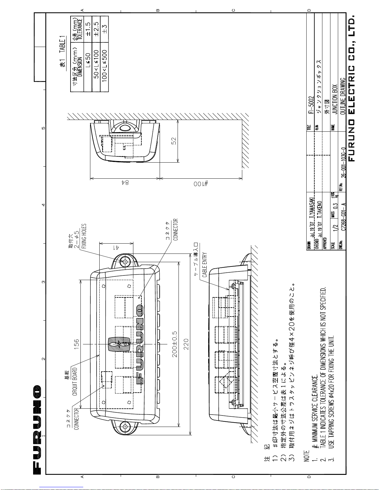
The junction box is required when connecting CAN bus network. This
section covers wiring of the junction box. For how to mount the junction
box, see its installation instructions, issued separately.
CH3 DROP - CH5 DROP and BACKBONE are socket-and-plug-type terminal blocks. Detach plug to connect wiring to it, by rocking it back and
forth with your fingers. Remove approx. 6 mm of the sheath from the end
of wires and twist wires. Loosen fixing screw in the plug, insert wire into
hole and tighten fixing screw. Set plug to socket.
12 VDC
CN1
12VDC
CN3
DROP
CN2
BACKBONE
FI-501/502/503/504/505/506/507
CAN bus
Device
Fix cable with cable
tie (supplied).
CN4
DROP
CN5
DROP
Fixing screw
Hole for wire
Wire
Twist
How to insert wire
6mm
Sheath
How to fabricate cable
White
Red
Blue
Black
Drain wire
Page 28
3. INSTALLATION
20
Terminal resistor
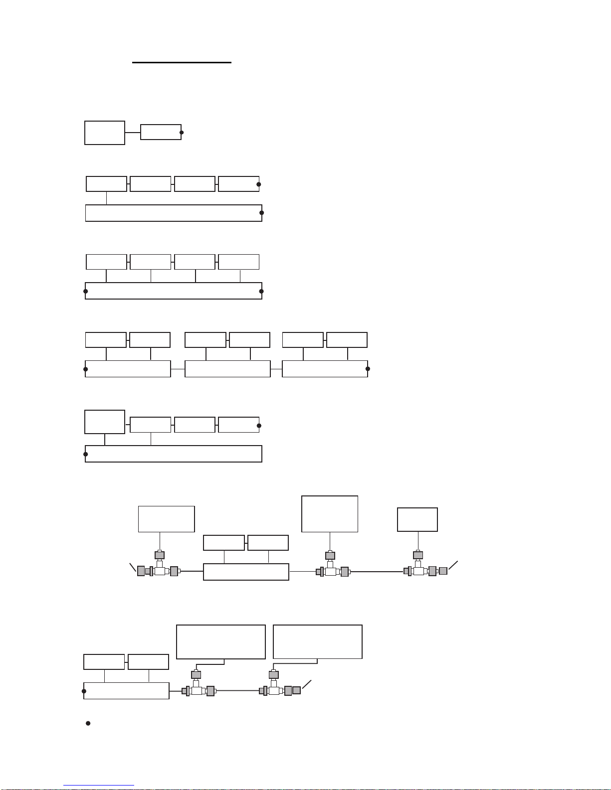
The illustration below show various system configurations and what units
to activate the terminal resistor.
= Terminal resistor ON
FI-50x
Smart
Sensor
Smart sensor+FI-50x
FI-50x
Multiple FI-50 series instruments, FI-5002, drop cabling
FI-5002
FI-50x
FI-50x FI-50x
Drop cable
FI-50x
FI-5002
FI-50x
FI-50x FI-50x
Multiple FI-50 series instruments, FI-5002
FI-50x
FI-5002
FI-50x FI-50x
Multiple FI-50 series instruments, FI-5002, smart sensor
Smart
Sensor
Multiple FI-50 series instruments, multiple FI-5002
FI-5002
FI-50x FI-50x
FI-5002
FI-50x FI-50x
FI-5002
FI-50x FI-50x
Multiple FI-50 series instruments, FI-5002, heading sensor, smart sensor
Multiple FI-50 series instruments, FI-5002, NMEA 2000, CAN bus sensors
FI-5002
FI-50x FI-50x
Heading
Sensor
(ex. SC-30)
Smart
Sensor
T-connector
T-connector
T-connector
NMEA 2000
Sensor
FI-5002
FI-50x FI-50x
CAN bus Device
or
NMEA 2000 Sensor
T-connector
CAN bus Device
or
NMEA 2000 Sensor
T-connector
Terminator
Terminator
Terminator
Page 29
3. INSTALLATION
21
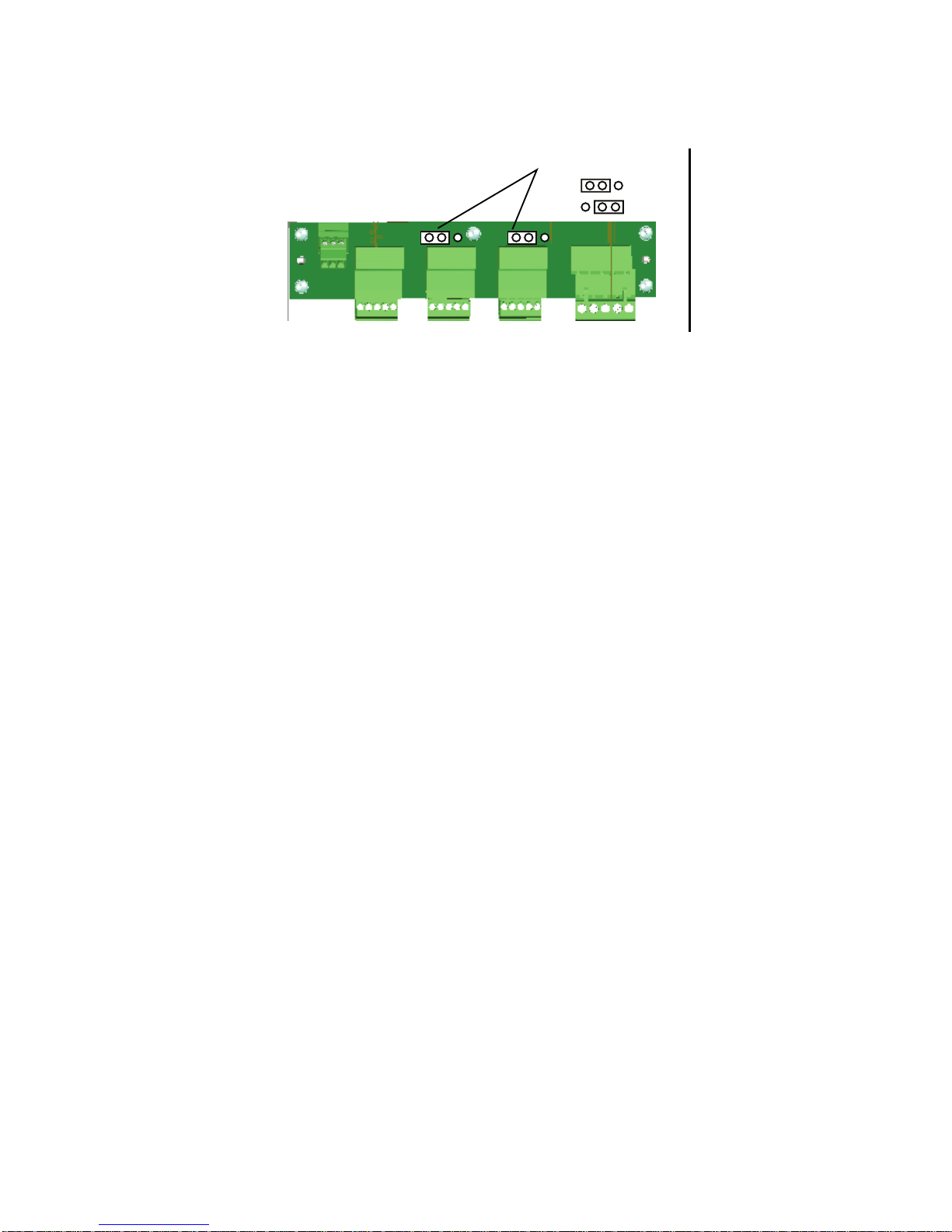
Turn on the terminal resistor in the junction box when the FURUNO CAN
bus and/or NMEA 2000 sensor(s) connected to it do not have a terminal
resistor.
For how to turn on the terminal resistor in a FI-50 series instrument, see
paragraph 3.4.2 “Setup2 menu”.
3.4 Setting Up
Your instrument is pre-programmed with factory default settings, which
may or may not be suited to your vessel. Therefore, it is necessary to initialize the instrument for use with your vessel. This should be done immediately after completion of the installation.
Two sets of setup menus are provided: setup1 and setup2. The setup1
menu provides system parameters and the setup2 menu has user settings.
3.4.1 Setup1 menu
The setup1 menu contains system parameters which optimize the instrument for use on your vessel. Follow the procedure below to access and
set parameters.
1. Press the APP/TRUE and SELECT/CLEAR keys momentarily to
enable the setup1 menu. The Depth unit selection screen appears,
with the depth unit flashing. (See the illustration on the next page.)
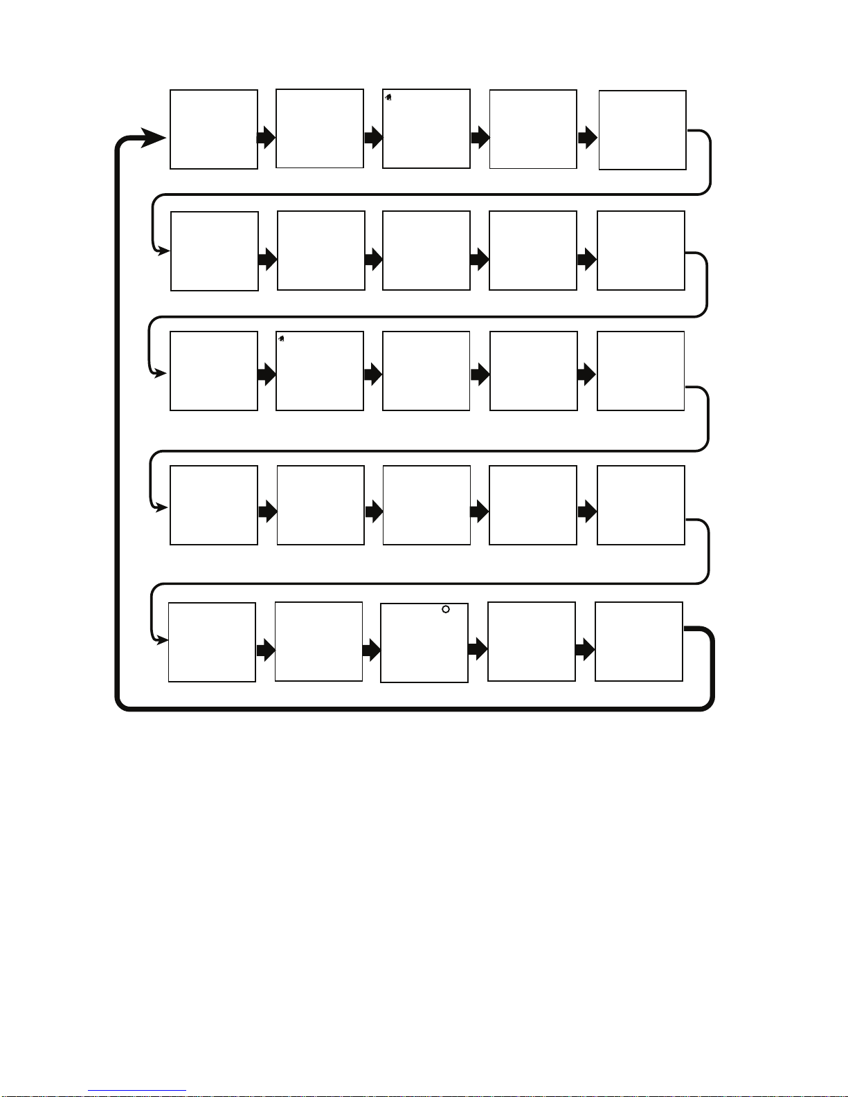
2. Use the DISP key to select a menu item. Each press of the key
changes the menu item in the sequence shown in the illustration on
the next page.
Terminal Resistor
OFF:
ON:
Page 30
3. INSTALLATION
22
.
3. Use the APP/TRUE or SELECT/CLEAR key to set value or select
option.
VMG key: Decrement value
SELECT/CLEAR key: Increment value or select option.
4. To continue, press the DISP key to select another menu item.
5. To save settings and restore normal operation, press the APP/TRUE
and SELECT/CLEAR keys together.
Depth unit
DPTH M
CAL
Shallow alarm lock
SHWLOCK
CAL
Off
Depth response
DPT RES
CAL
3
Speed unit
SPD KT
CAL
Speed unit resolution
SPD
CAL
0.01
Speed offset
SPD
--- --- ---
1.00
Speed response
SPD RES
CAL
0
VMG response
VMG RES
CAL
3
Audio alarm
enable/disable
TIMER
CAL
On
Wind data selection
WIND
CAL
F
Wind unit
WIND KT
CAL
Wind speed
adjustment
WINDADJ
CAL
1.0
Wind angle offset
ANGLE S
CAL
0
Wind speed
response
WSPDRES
CAL
3
Heading reference
HDG MAG
CAL
Heading response
HDG RES
CAL
0
Heading lock
HDGLOCK
CAL
LOC
Depth offset
DPTH M
0.0
CAL
LOG unit
LOG NM
SOG response
SOG RES
CAL
0
TIME HR
--- ---:--- ---
TEMP C
W TEMP FUEL L
Time format
CAL
12
Local time
CAL
0
Water temp. unit
CAL
Water temp. offset
CAL
0.0
Fuel unit
CAL
CAL
CAL
Page 31
3. INSTALLATION
23
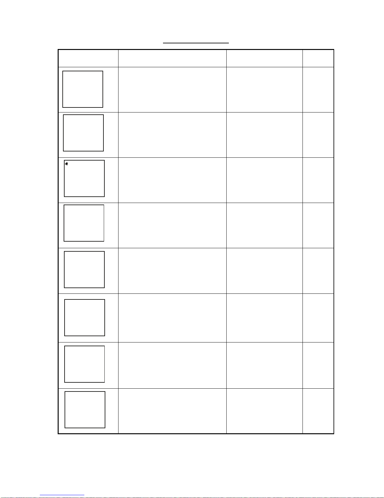
Setup1 menu items
Display Function
Setting range or
options
Default
setting
Select depth unit. M (Meter),
FT (Feet)
M
Set depth offset. -99 - +99 0.0
Lock/unlock shallow alarm setting. ON, OFF OFF
Set depth response. The lower the
setting the faster the response to
change in depth.
0 - 12 3
Select speed unit. KT (Knot),
MPH (Miles/Hour),
KMH (Kilometers/Hour)
KT
Select speed resolution. Select
number of places to show after
decimal point.
0.01, 0.1 0.01
Set speed adjustment.
(STW only)
0.30 - 2.50 1.00
Select log unit. NM (Nautical Mile),
SM (Statute Mile),
KM (Kilometer)
NM
DPTH M
CAL
DPTH M
0.0
CAL
SHWLOCK
CAL
OFF
DPT RES
CAL
3
SPD KT
CAL
SPD
CAL
0.01
SPD
--- --- ---
1.00
CAL
LOG NM
CAL
Page 32
3. INSTALLATION
24
Set speed response. The lower the
setting the faster the response to
change in speed.
0 - 12 0
Set SOG response. The lower the
setting the faster the response to
change in speed over ground.
0 - 12 0
Set VMG response. The lower the
setting the faster the response to
change in velocity made good.
0 - 12 3
Enable/disable the timer alarm’s
audio alarm.
ON, OFF ON
Select source of wind data. Select
“r” for second unit.
F: For FI-5001 (Furuno
Sensor), r: repeater
F
Select wind unit. KT (Knot),
M/S (Meters/Second)
KT
Set wind speed
adjustment.
0.3 - 2.5 1.0
Set wind angle offset. S 0
° - 180°
P 1° - 179°
0
Set wind speed response.
The higher the setting the faster
the response to change in wind
speed.
0 - 12 3
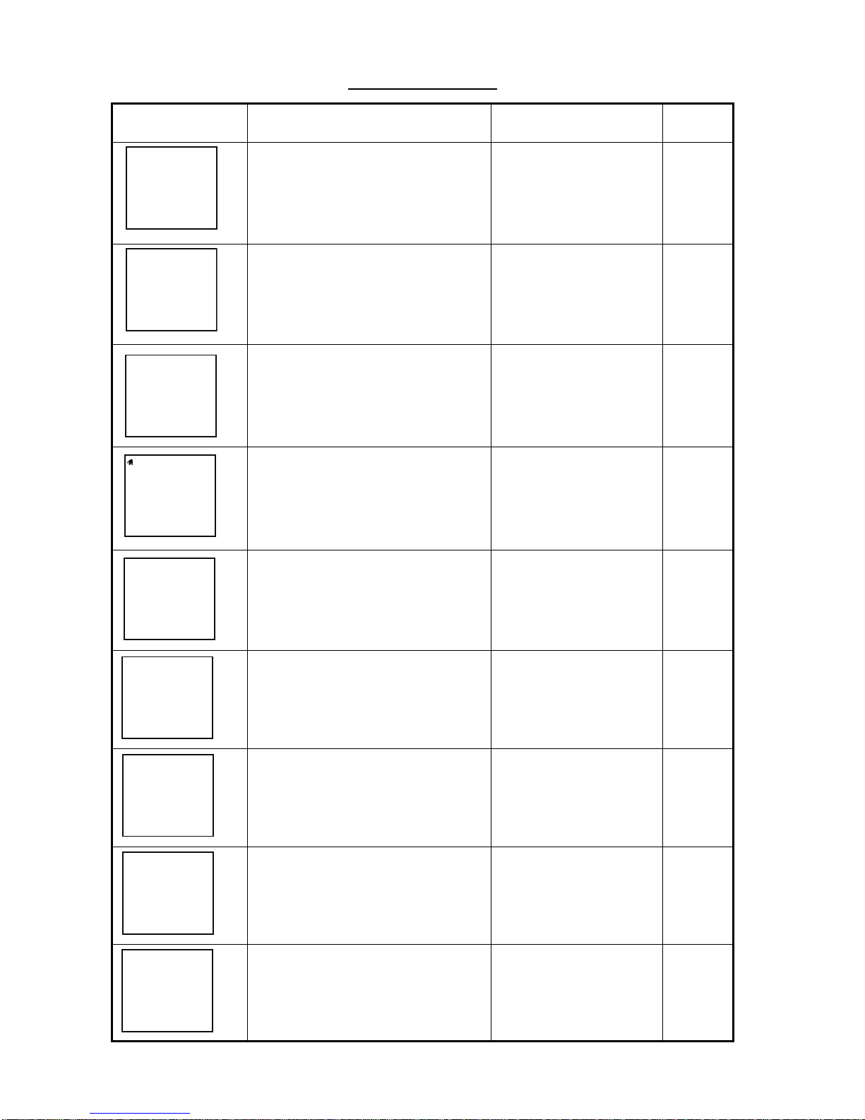
Setup1 menu items
Display Function
Setting range or
options
Default
setting
SPD RES
CAL
0
SOG RES
CAL
0
VMG RES
CAL
3
TIMER
CAL
On
WIND
CAL
F
WIND KT
CAL
WINDADJ
CAL
1.0
ANGLE S
CAL
0
WSPDRES
CAL
3
Page 33
3. INSTALLATION
25
Select true or magnetic bearing. MAG (Magnetic),
TRU (True
MAG
Select heading type to display
when
activating locked heading.
LOC (Locked),
CUr (Current)
LOC
Set heading response. The lower
the setting the faster the response
to change in heading.
0 - 12 0
Select time format. 12, 24 (hour) 12
Use local time. Enter time difference between local time and GMT
to use local time.
-12 - +12 0
Select water temperature unit.
°C, °F °C
Set water temperature
offset.
-99 - +99 0
Select fuel unit. L (Liter),
G (Gallon)
L
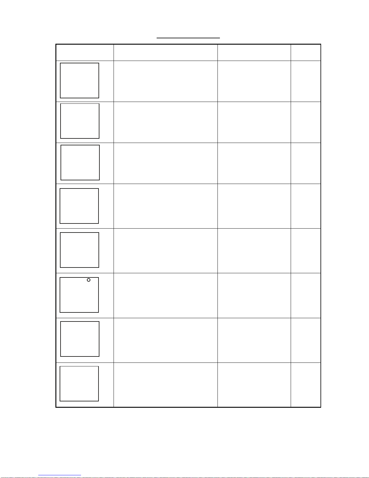
Setup1 menu items
Display Function
Setting range or
options
Default
setting
HDG MAG
CAL
HDGLOCK
CAL
LOC
HDG RES
CAL
0
TIME HR
CAL
12
--- ---:--- ---
CAL
0
TEMP C
CAL
W TEMP
CAL
0.0
FUEL L
CAL
Page 34
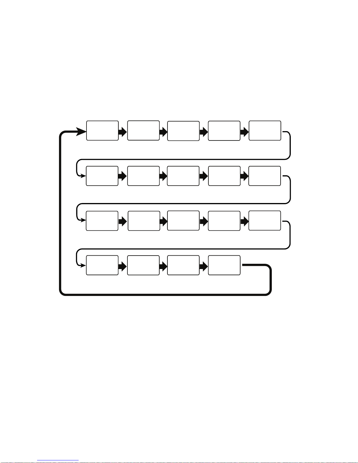
3. INSTALLATION
26
3.4.2 Setup2 menu
The setup 2 menu contains user settings which once preset do not require frequent adjustment.
1. Press and hold down the APP/TRUE and SELECT/CLEAR keys
together (about 5-6 seconds) to enable the user settings menu. The
software version of CPU1 appears. (See the illustration below.)
2. Press the DISP key to choose menu item. Each press of the key
changes the menu item in the sequence shown below.
3. Use the SELECT/CLEAR key to select setting.
4. To continue, press the DISP key to select another item.
5. To save settings and restore normal operation, press the APP/TRUE
and SELECT/CLEAR keys together.
Xxxxx*
Program ver.
no. (CPU2)
Xxxxx*
Program ver.
no. (CPU1)
KEYBEEP
CAL
Key
beep
ON
Auto
brilliance
A BRILL
CAL
ON
ALT
Alternating
displays
CAL
OFF
Setup 1 menu
SETUP
CAL
ON
Terminal
resistor
rES
CAL
OFF
Synchronization
SYNCHRO
CAL
ON
Depth
displays
DEPTH
CAL
ON
Speed
displays
SPEED
CAL
ON
Environment
displays
ENVIRO
CAL
ON
Nav
displays
NAVI
CAL
ON
Heading
displays
HEADING
CAL
ON
Wind
displays
WIND
CAL
ON
Timer
displays
TIMER
CAL
ON
Autopilot
displays
A PILOT
CAL
ON
Engine
displays
ENGINE
CAL
ON
Demo
mode
DEMO
CAL
OFF
Restore factory
defaults
RESET
CAL
OFF
*XXxx=program and program ver. nos.
Page 35
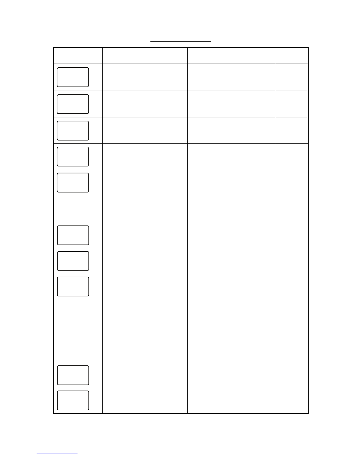
3. INSTALLATION
27
Setup2 menu items
Display Function
Setting range or
options
Default
setting
Software version of CPU1.
X=program no. and
xxxx=program version no.
--
Software version of CPU2.
X=program no. and
xxxx=program version no.
--
Turn key beep on/off. ON, OFF ON
Auto brilliance on/off. ON, OFF ON
Enable/disable alternating
displays.
OFF
1: Depth/boat spd
2: Boat spd/water temp.
3: Depth/water temp.
4: Depth/boat spd/water temp.
5: Roll/pitch
6: Latitude/Longitude
OFF
Enable/disable access to the
setup1 menu.
ON, OFF ON
Turn the terminal resistor on/
off.
ON, OFF OFF
Turn on/off synchronization of
FI-50 series instruments.
ON:
Synchronize FI-50
instruments having this
setting.
OFF:
Turn off synchronization.
A:
Synchronize FI-50 instru ments having this setting.
b:
Synchronize FI-50 instru ments having this setting.
ON
Turn depth displays on/off. ON, OFF ON
Turn speed displays on/off. ON, OFF ON
Xxxxx
Xxxxx
KEYBEEP
CAL
ON
A BRILL
CAL
ON
ALT
CAL
OFF
SETUP
CAL
ON
rES
CAL
OFF
SYNCHRO
CAL
ON
DEPTH
CAL
ON
SPEED
CAL
ON
Page 36
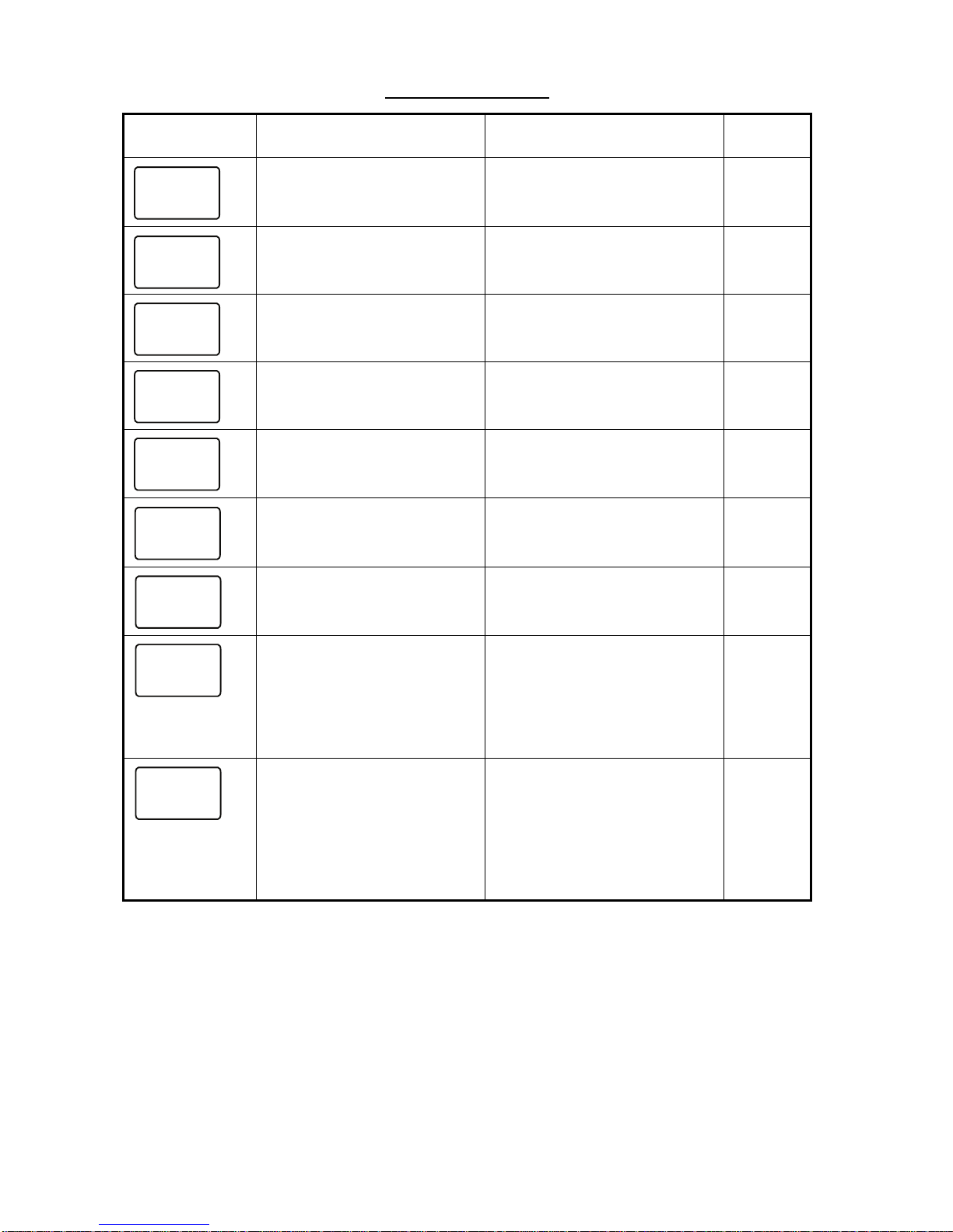
3. INSTALLATION
28
Turn timer displays on/off. ON, OFF ON
Turn wind displays on/off. ON, OFF ON
Turn heading displays on/off. ON, OFF ON
Turn navigation displays
on/off.
ON, OFF ON
Turn environmental displays
on/off.
ON, OFF ON
Turn autopilot displays on/off. ON, OFF ON
Turn engine displays on/off. ON, OFF ON
Demo mode. To enable,
press the SELECT/CLEAR
key. Depth is shown.
To disable and return to this
menu, press and hold down
the SELECT/CLEAR key.
ON, OFF OFF
Restore factory defaults.
To restore factory defaults,
press and hold down the
SELECT/CLEAR key to
show ON. Press the key
again. A beep sounds upon
completion.
ON, OFF OFF
Setup2 menu items
Display Function
Setting range or
options
Default
setting
TIMER
CAL
ON
WIND
CAL
ON
HEADING
CAL
ON
NAVI
CAL
ON
ENVIRO
CAL
ON
A PILOT
CAL
ON
ENGINE
CAL
ON
DEMO
CAL
OFF
RESET
CAL
OFF
Page 37

FI-504 MULTI
E7269S01A1
SP-1
SPECIFICATIONS OF
FI-504 MULTI
1 GENERAL
1.1 Indication system Segment LCD
1.2 Brilliance 4 steps
1.3 Contrast 3 steps
1.4 Display Contents Depth, speed, wind speed, wind angle,
timer, environmental information (water
temperature, air temperature, air
pressure, dewpoint, wind chill
temperature), rudder angle
1.5 Number of Port CAN bus, 2 ports
1.6 Mount Method Surface or flush mount
2 JUNCTION BOX (OPTION)
2.1 Number of Port CAN bus Drop: 6 ports,
CAN bus Backbone: 2 ports
2.2 Circuit Protection Reverse, short, over current
3 POWER SUPPLY AND POWER CONSUMPTION
3.1 Display Unit 12 VDC, less than 0.1 A
3.2 Junction Box
12 VDC, less than 1 A, max. 2A connectable
4 ENVIRONMENTAL CONDITIONS
4.1 Useable Temperature Range -15°C - +55°C
4.2 Relative Humidity Less than 95% (+40°C)
4.3 Waterproofing
Display Unit IP56
Junction Box IPX0
4.4 Vibration - 2 Hz-5 Hz and up to 13.2 Hz with an
excursion of ±1 mm ±10% (7 m/s
2
maximum acceleration at 13.2 Hz);
- above 13.2 Hz and up to 100 Hz with a
constant maximum acceleration of 7 m/s2
5 COATING COLOR
5.1 Display Unit N2.5
5.2 Junction Box N2.5
Page 38

FI-507 MULTI XL
SP - 2 E7277S01A
SPECIFICATIONS OF
FI-507 MULTI XL
1 GENERAL
1.1 Indication system Segment LCD
1.2 Brilliance 4 steps
1.3 Contrast 3 steps
1.4 Display contents Depth, Ship’s speed, Wind speed/angle, Date, Time, Bearing
Environmental information
*1
, Navigational information,
Rudder angle, Engine information
*2
1.5 Number of port CAN bus: 2 port
1.6 Mount method Surface or flush mount
*1) Battery voltage, date, time, water temperature, air temperature, air pressure, humidity,
wind chill temperature and dew point
*2) Fuel consumption, fuel efficiency and engine speed
2 JUNCTION BOX
2.1 Number of port CAN bus drop: 6, CAN bus backbone: 2
2.2 Circuit protection Reverse, short, over current
3 POWER SUPPLY
3.1 Main unit 12 VDC: 0.1 A
3.2 Junction box 12 VDC: 1 A
4 ENVIRONMENTAL CONDITION
4.1 Ambient temperature -15°C to +55°C
4.2 Relative humidity 95% at 40°C
4.3 Degree of protection
Main unit IP56
Junction box IPX0
4.4 Vibration - 2 Hz-5 Hz and up to 13.2 Hz with an excursion of
±1 mm ±10% (7 m/s
2
maximum acceleration at 13.2
Hz);
- above 13.2 Hz and up to 100 Hz with a
constant
maximum acceleration of 7 m/s
2
5 COATING COLOR
5.1 Main unit N2.5
5.2 Junction box N2.5
Page 39
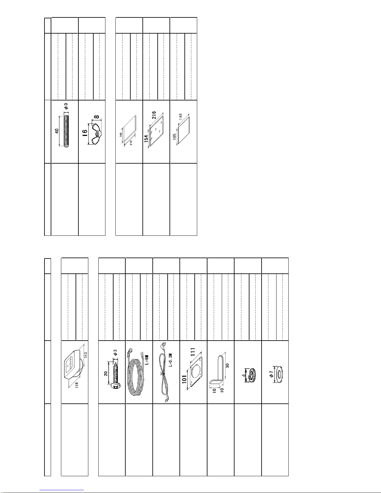
NAME OUTLINE Q'TYDESCRIPTION/CODE №
PACKING LIST
26AA-X-9860 -4
FI-504
1/1
NAME OUTLINE Q'TYDESCRIPTION/CODE №
ユニット UNIT
表示部
MONITOR UNIT
1
FI-504
000-011-745-00
工事材料 INSTALLATION MATERIALS
CP26-00600
+ナベタッピンネジ 1シュ
SELF-TAPPING SCREW
4
3X20 SUS304
000-163-884-10
ケーブル組品
CABLE ASSEMBLY
1
FI-50-DROP-6M
001-105-810-10
ケーブル組品0.3M
CABLE ASSEMBLY 0.3M
1
FI-50-CHAIN-0.3M
001-105-820-10
サーフェスマウントスポンジ
SPONGE
1
TZ7583002AO
000-167-832-10
パネルリムーバー
PANEL REMOVER
1
19-028-3124-1
100-340-471-10
バネ座金
SPRING WASHER
2
M3 SUS304
000-167-404-10
ミガキ丸平座金
FLAT WASHER
2
M3 SUS304
000-167-453-10
寸切ボルト
BOLT
2
M3X40 SUS304
000-167-804-10
蝶ナット
WING NUT
2
M3 SUS304
000-167-826-10
図書 DOCUMENT
取扱説明書(英)
OPERATOR'S MANUAL
1
OME-72690-*
000-167-334-1*
操作要領書
OPERATOR'S GUIDE
1
**
OS*-72690-*
000-167-295-1*
内部終端ノ設定
INTERNAL RESISTOR
1
C72-00705-*
000-168-501-1*
コ-ド番号末尾の[**]は、選択品の代表コードを表します。
CODE NUMBER ENDING WITH "**" INDICATES THE CODE NUMBER OF REPRESENTATIVE MATERIAL.
(略図の寸法は、参考値です。 DIMENSIONS IN DRAWING FOR REFERENCE ONLY.)
26AA-X-9860
型式/コード番号が2段の場合、下段より上段に代わる過渡期品であり、どちらかが入っています。 なお、品質は変わりません。
TWO TYPES AND CODES MAY BE LISTED FOR AN ITEM. THE LOWER PRODUCT MAY BE SHIPPED IN PLACE OF
THE UPPER PRODUCT. QUALITY IS THE SAME.
Page 40
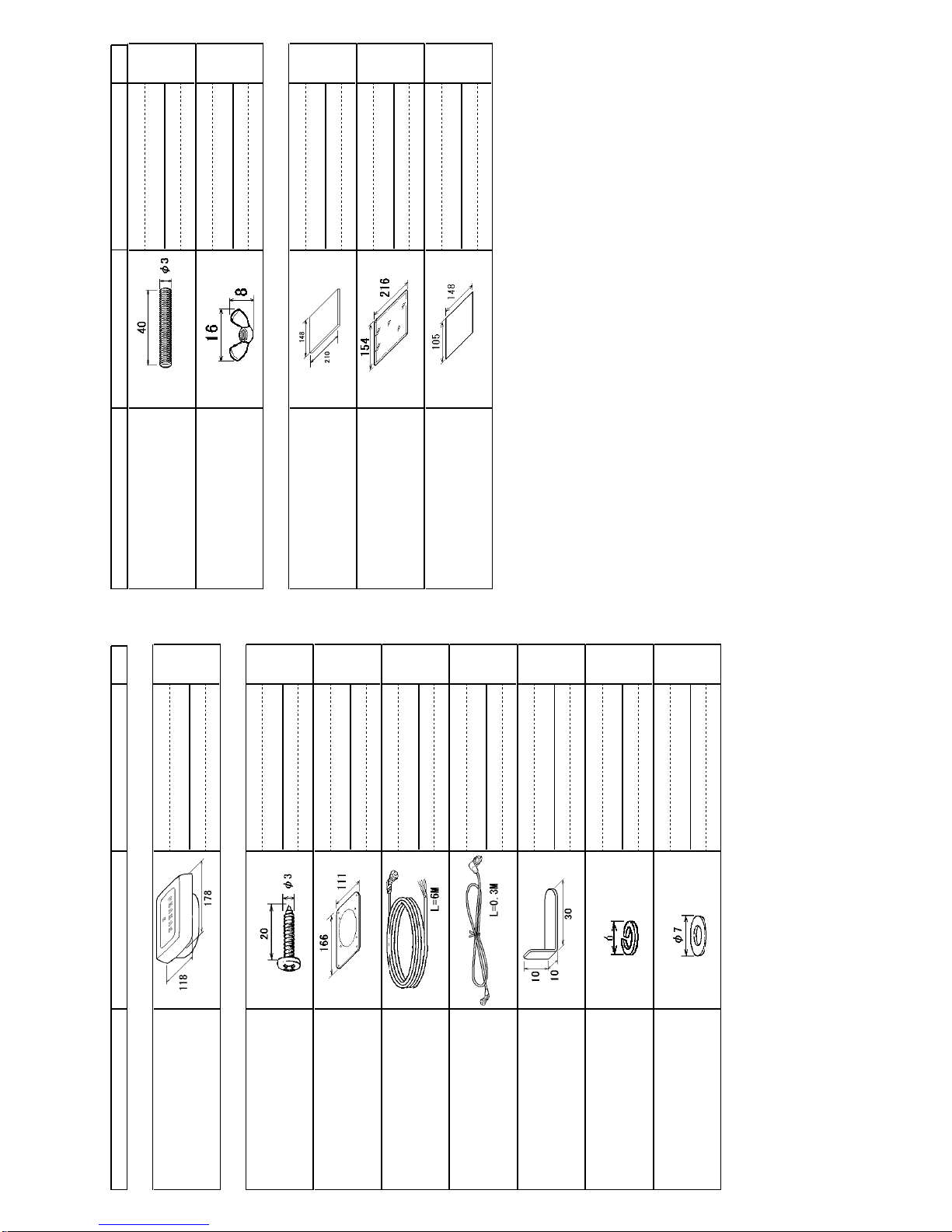
NAME OUTLINE Q'TYDESCRIPTION/CODE №
PACKING LIST
26AA-X-9863 -2
FI-507
1/1
NAME OUTLINE Q'TYDESCRIPTION/CODE №
ユニット UNIT
表示部
MONITOR UNIT
1
FI-507
000-015-729-00
工事材料 INSTALLATION MATERIALS
CP26-00800
+ナベタッピンネジ 1シュ
SELF-TAPPING SCREW
4
3X20 SUS304
000-163-884-10
SマウントスポンジXL
SURFACE MOUNTING
1
TZ7583059A0
000-170-617-10
ケーブル組品
CABLE ASSEMBLY
1
FI-50-DROP-6M
001-105-810-10
ケーブル組品0.3M
CABLE ASSEMBLY 0.3M
1
FI-50-CHAIN-0.3M
001-105-820-10
パネルリムーバー
PANEL REMOVER
1
19-028-3124-1
100-340-471-10
バネ座金
SPRING WASHER
4
M3 SUS304
000-167-404-10
ミガキ丸平座金
FLAT WASHER
4
M3 SUS304
000-167-453-10
寸切ボルト
BOLT
4
M3X40 SUS304
000-167-804-10
蝶ナット
WING NUT
4
M3 SUS304
000-167-826-10
図書 DOCUMENT
取扱説明書(英)
OPERATOR'S MANUAL
1
OME-72690-*
000-167-334-1*
操作要領書(英)
OPERATOR'S GUIDE (EN)
1
OSE-72770-*
000-170-641-1*
内部終端ノ設定
INTERNAL RESISTOR
1
C72-00705-*
000-168-501-1*
(略図の寸法は、参考値です。 DIMENSIONS IN DRAWING FOR REFERENCE ONLY.)
26AA-X-9863
型式/コード番号が2段の場合、下段より上段に代わる過渡期品であり、どちらかが入っています。 なお、品質は変わりません。
TWO TYPES AND CODES MAY BE LISTED FOR AN ITEM. THE LOWER PRODUCT MAY BE SHIPPED IN PLACE OF
THE UPPER PRODUCT. QUALITY IS THE SAME.
Page 41
26/Oct/09R.Esumi
Page 42
26/Oct/09R.Esumi
Page 43
Jul.24'07R.Esumi
Page 44
9/Dec/08R.Esumi
Page 45
9/Dec/08R.Esumi
Page 46
12VDC
2
43
A
1
B
C
NOTE
*1: OPTION.
*2: USE A TERMINAL BOX (NO-PROTECTION) WHEN THE SUPPLIED CABLE IS CUT.
注記
*1)オプション。
*2)ケーブルを切断する場合は、ターミナルボックス(非防水)を使用のこと。
*3)短絡しないように、端末を処理する。
*3: PROTECT CABLE ENDS TO PREVENT SHORT-CIRCUIT.
DRAWN
CHECKED
APPROVED
DWG.No.
TITLE
NAME
名称
INTERCONNECTION DIAGRAM
相互結線図
REF.No.
SCALE MASS
kg
インスツルメント
INSTRUMENT
T.YAMASAKI
T.TAKENO
FI-501/502/503/504/505/506/507
12345
SHIELD
NET-S
NET-C
NET-H
NET-L
12345
SHIELD
NET-S
NET-C
NET-H
NET-L
12345
SHIELD
NET-S
NET-C
NET-H
NET-L
12345
SHIELD
NET-S
NET-C
NET-H
NET-L
12345
SHIELD
NET-S
NET-C
NET-H
NET-L
12345
SHIELD
NET-S
NET-C
NET-H
NET-L
同上
DITTO
同上
DITTO
同上
DITTO
同上
DITTO
REDアカ
BLKクロ
チャ BRNダイキ
ORG
YEL
12345
6
TERMINAL BOX
FI-5001-TERMINAL
ターミナルボックス
*2
WIND TRANSDUCER
風向風速センサー
SHIELD
NET-S
NET-C
NET-H
NET-L
12345
インスツルメント
INSTRUMENT
-SR7000
LTW12-05AFFM
FI-501/502
単品で使用するとき
USING INDEPENDENTLY
RED
BLK
アカクロシロ
アオ
WHT
BLU
FI-50-DROP,6m,φ6
12VDC
(+)
(-)
(1/5/10/20m *1)
FI-50-CHAIN,0.3m,φ6
SHIELD
NET-S
NET-C
NET-H
NET-L
12345
インスツルメント
INSTRUMENT
SHIELD
NET-S
NET-C
NET-H
NET-L
12345
FI-503/504
505/506
-SR7000
LTW12-05AFFM
-SR7000
LTW12-05AMMM
(1/5/10/20m *1)
FI-50-CHAIN,0.3m,φ6
RED
BLK
アカ
クロ
シロ
アオ
WHT
BLU
RED
BLK
アカクロシロ
アオ
WHT
BLU
FI-50-DROP,6m,φ6
FI-50-DROP,6m,φ6
SHIELD
NET-S
NET-C
NET-H
NET-L
12345
インスツルメント
INSTRUMENT FI-501/502
SHIELD
NET-S
NET-C
NET-H
NET-L
12345
12345
6
WIND
GND
SPEED
DIR2
DIR1
+V
SHIELD
-SR7000
-SR7000
LTW12-05AFFM
LTWBD-06AFMM
LR7000
LTW12-05AMMM
FI-50-SENSOR-30M/50M,30/50m,φ4.3
SELECT
選択
NC
NC
*3
インスツルメント(最大26個)
INSTRUMENT (TOTAL: UP TO 26 SETS)
DEPEND ON CABLE AND CONNECTION CONDITIONS
ケーブルや接続条件により満足しない場合あり
FI-5001/5001L
507
CN3 DROP_U
CN3 DROP_L
CN4 DROP_U
CN4 DROP_L
CN5 DROP_U
CN5 DROP_L
(+)
(-)
BLKクロ
SHIELD
123
ジャンクションボックス
FI-5002
*1
JUNCTION BOX
12345
SHIELD
NET-S
NET-C
NET-H
NET-L
12345
SHIELD
NET-S
NET-C
NET-H
NET-L
接続箱
JUNCTION BOX
接続箱
JUNCTION BOX
(BACKBONE)
(BACKBONE)
CN1 12VDC
CN2 BACKBONE_U
CN2 BACKBONE_L
CAN bus NETWORK
CAN bus NETWORK
CAN bus CABLE TOTAL LENGTH: UP TO 80m
CAN busケーブル長総合計:80m以下
CAN bus
CAN bus
CAN bus
CAN bus
CAN bus
シロ WHT
(VV-SA0.75x2C)
FI-5002-POWERCABLE,2m
28/Jan/10
28/Jan/10
C7266-C01- J
8/Mar/10R.Esumi
Page 47
タッピンネジ用穴(4ヵ所)
Fortappingscrews(4pcs.)
寸切りボルト用穴(2ヵ所)
Forbolts(2pcs.)
Page 48
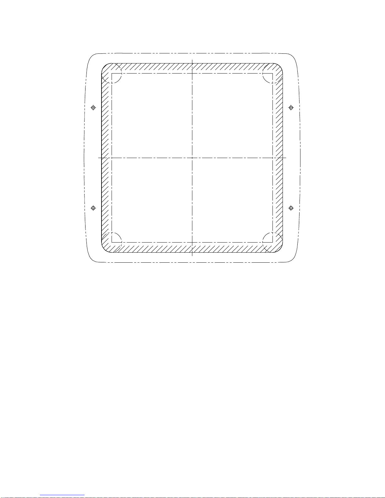
FI‑50シリーズ表示部 フラッシュマウント用型紙
FI‑50seriesDisplayunitFlushMountTemplate
Page 49
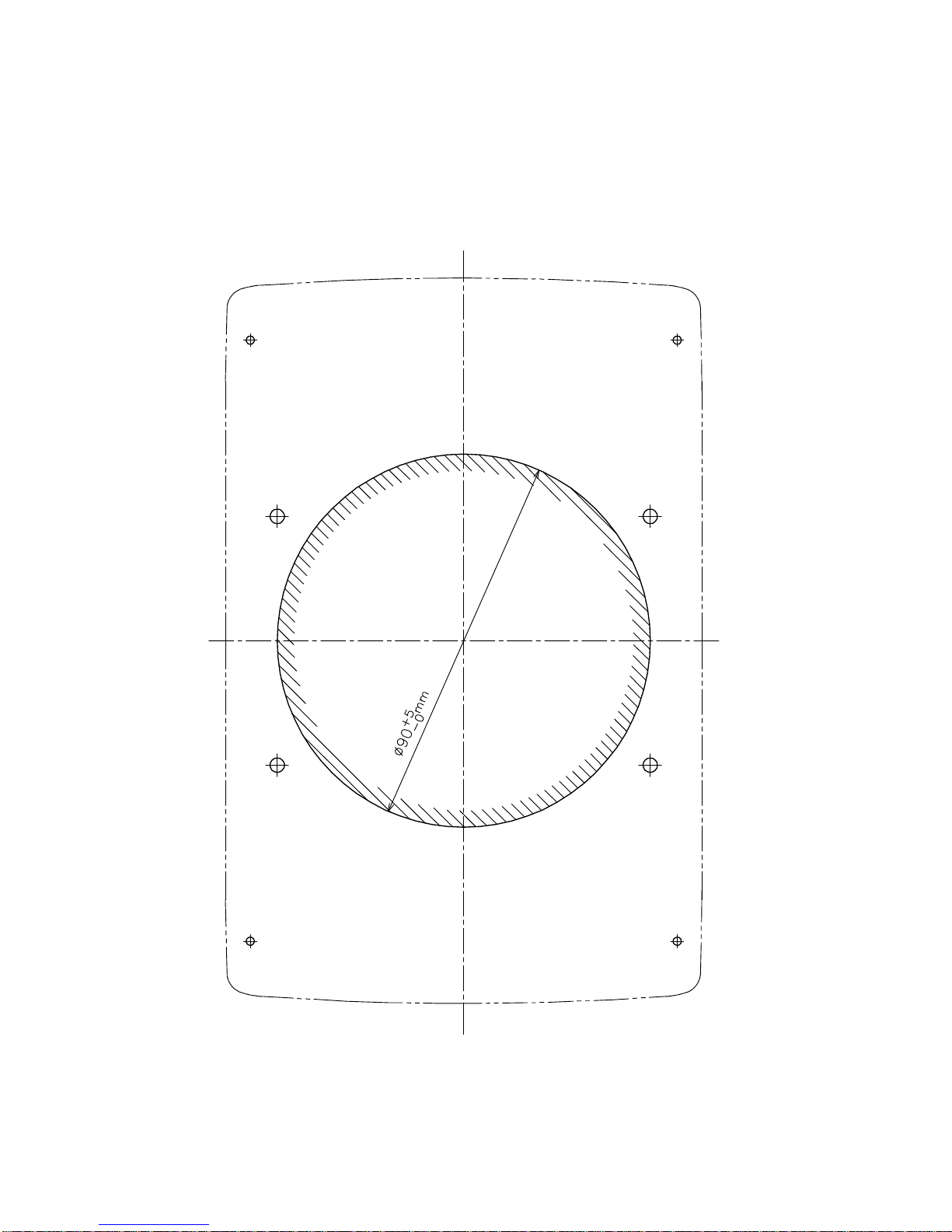
タッピンネジ用穴(4カ所)
For tapping screws (4 pcs.)
寸切りボルト用穴(4カ所)
Forbolts (4 pcs.)
Page 50
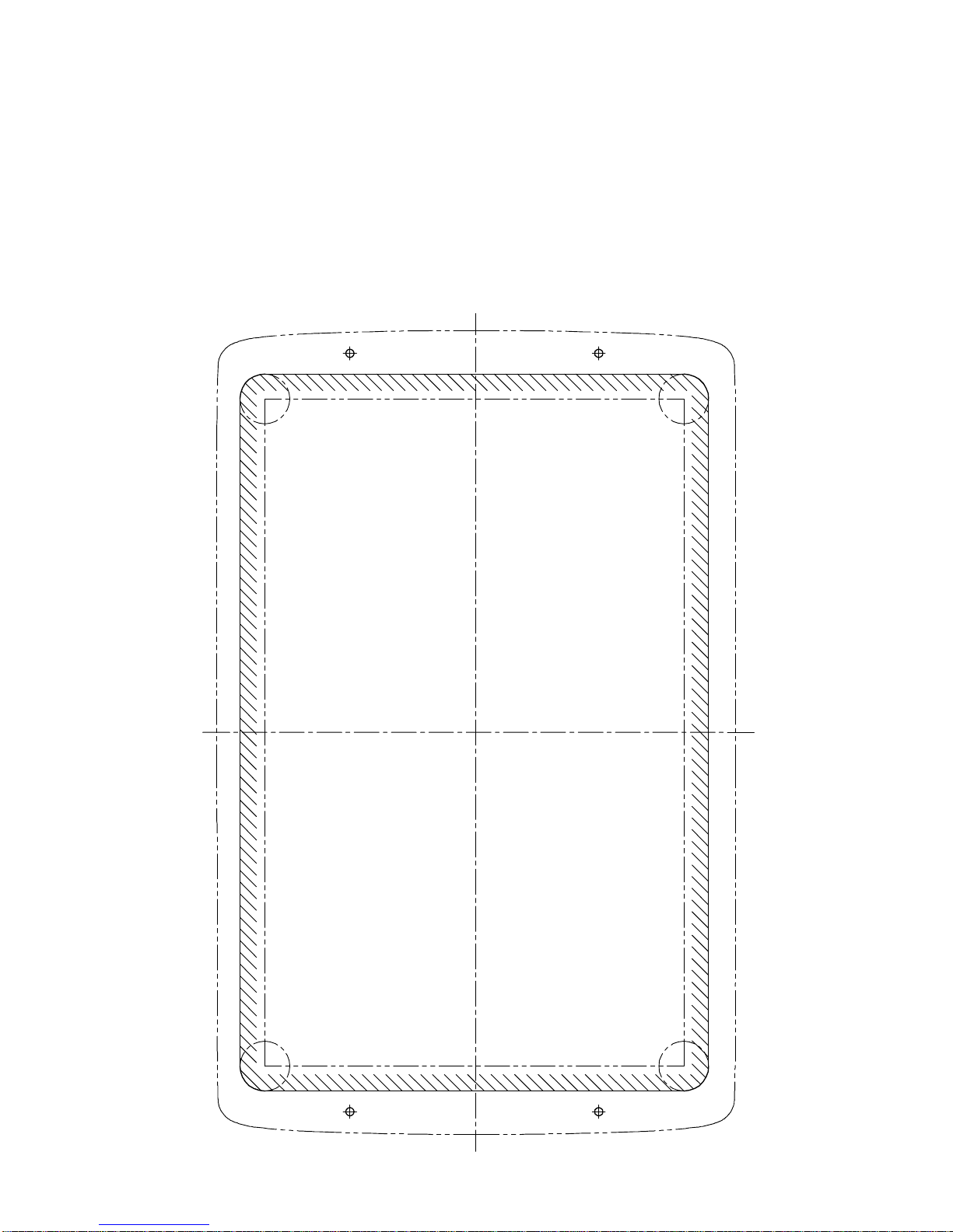
FI-507 フラッシュマウント用型紙
FI-507 Flush Mount Temlete
 Loading...