

Page 1

0
Page 2

1
Page 3
2
Page 4
3
Page 5

4
1 Part specification....................................................................................................5
2 Installation...............................................................................................................8
2.1 Location of the Server....................................................................................9
2.2 Installing the Server .......................................................................................9
2.3 Installing the transducers.............................................................................10
2.4 Connecting optional accessories.................................................................10
2.4.1 Man over board (MOB) push-button ........................................................11
2.4.2 Tactical function push-button...................................................................11
2.4.3 Extra alarm buzzer...................................................................................11
2.4.4 FI-30 instruments ....................................................................................12
2.5 Connecting instrument lighting.....................................................................13
2.6 How to use the NMEA ports.........................................................................13
2.7 Connecting a NMEA instrument IN to the Server.........................................14
2.8 Connecting a NMEA instrument OUT from Server.......................................15
2.9 Connecting the power supply.......................................................................15
2.10 Compatibility with our previous transducers ................................................16
2.10.1 Log transducer.....................................................................................16
2.10.2 Depth transducer.................................................................................16
2.10.3 Wind transducer ..................................................................................17
2.10.4 Compass transducer ...........................................................................17
2.10.5 NMEA transducers...............................................................................18
2.11 NMEA...........................................................................................................19
2.11.1 Transmit NMEA sentences OUT from Server......................................19
2.11.2 Change NMEA sentences OUT from Server .......................................20
2.11.3 Receive NMEA sentences IN to Server...............................................21
2.12 Special NMEA sentences ............................................................................22
3 Maintenance and fault finding .............................................................................24
3.1 Maintenance ................................................................................................24
3.2 Fault finding .................................................................................................24
3.2.1 General....................................................................................................24
3.2.2 Fault - action............................................................................................25
3.2.3 Error messages .......................................................................................27
4 Specifications........................................................................................................28
4.1 Technical specifications...............................................................................28
4.2 FI-30 databus introduction and user policy..................................................28
4.3 Equipment Lists ...........................................................................................29
Page 6

5
1 Part specification
Items delivered with the Server
Qty. Description
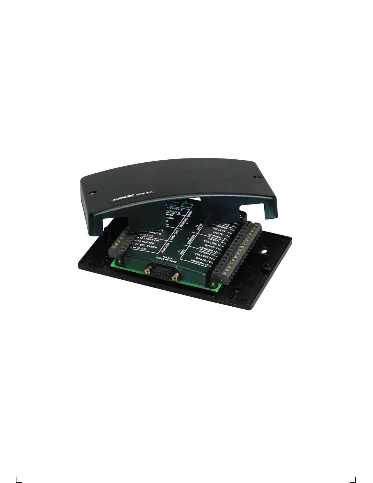
1 FI-30 Server
4 Server mounting screws
2 Plastic cable straps
1 Power cables, red and black, 3 m (9 ft ) each
Page 7

6
Welcome aboard the Nexus Network!
Thank you for choosing FI-30 and welcome to the world of the Nexus Network.
Through this manual we would like to help you install, operate and understand your
new Nexus Network.
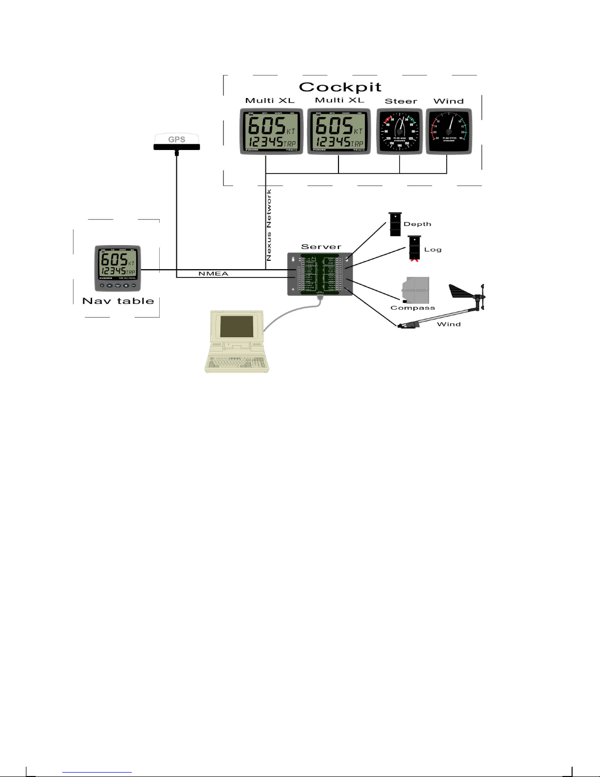
The Server is the "heart" of your Nexus Network, to which transducers for speed,
depth, heading, wind and navigation (GPS) are connected.
From the Server the single Nexus Network cable transmits power and data to the
instruments, which repeat the information sent from the Server, or other FI-30
transducers.
The Nexus Network is designed with the industry standard RS 485 databus, which
allows you to connect up to 32 FI-30 instrument units on the single Nexus Network
cable, thereby allowing you the flexibility to easily develop your system. The Nexus
Network is capable of carrying data 10 times faster than NMEA 0183.
The connection system, with a single 5 mm (1/5") cable and 4-pole jack plugs with
cable protectors, makes the installation easy. No need to drill big holes and the cable
can be cut to exact lengths. The connections at the Server are colour coded and
marked with a number for easy reference.
FI-30 Multi Control is a multi function instrument that displays a main and a subfunction together. You can easily "customise" your favourite combination of functions,
by using the unique method to move, copy and lock a sub-function.
The instruments large display gives you very good viewing possibilities from any
angle, even in bright sunlight. The display and the five push-buttons have red back
lighting which you can set to three different lighting levels.
A large selection of optional analogue repeaters and accessories are available. The
analogue steer pilot instrument particularly offers unique functions. When used
together with the steer reference function (AWA), you can actually steer after the wind
and "expand" the tacking or down wind angle.
To get the most out of your new FURUNO product, please read through this manual
carefully before you start your installation.
Again, thank you for choosing FURUNO. If you see us at a show, stop by and say
hello.
Good luck and happy boating!
Page 8
7
The FI-30 Server is equipped with fault finding LED:s. For more information, see
chapter 3.2.2
Page 9
8
2 Installation
• The installation includes 6 major steps:
1. Read the operation manual.
2. Plan where to install the transducers, Server and instruments.
3. Install the transducers, then the Server and instruments.
4. Run the cables.
5. Take a break and admire your installation.
6. Learn the functions and calibrate your system.
• Before you begin drilling ... think about how you can make the installation as neat
and simple as your boat will allow. Plan where to position the transducers, Server
and instruments. Think about leaving space for additional instruments in the future.
• A few "do nots" you should consider:
− Do not cut the cables too short. Allow extra cable length at the
Server so it can be disconnected for inspection without having to
disconnect all attached cables.
− Do not place sealant behind the display. The instrument gasket
eliminates the need for sealant.
− Do not run cables in the bilge, where water can appear.
− Do not run cables close to fluorescent light sources, engine or radio
transmitting equipment to avoid electrical disturbances.
− Do not rush, take your time. A neat installation is easy to do.
• The following material is needed:
Wire cutters and strippers
Small and large philips and small flat head screw driver
Hole saw for the instrument clearance hole 63 mm (2½")
2.8 mm (0.11") drill for the mounting holes
Plastic cable ties
If the cable is not long enough, you can buy the optional 8 m (26 ft) extension
cable. The same 4-pole FI-30 cable is used for all connections.
If you are doubtful about the installation, obtain the services of an experienced
technician.
Page 10
9
2.1 Location of the Server
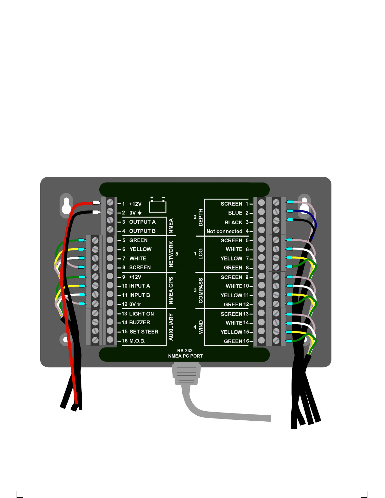
The Server must be mounted on a dry, flat and vertical surface below deck , at least
500 mm (20") from radio receiving equipment.
Locate the Server in the centre of the boat and close to the electrical panel if possible.
2.2 Installing the Server
Remove the Server cover from the base plate by removing the two screws. Drill the 4
screw holes using a 2.8 mm (0.11") drill. Mount the Server using the 4 mounting
screws.
Apply silicon paste on the screw terminal. Connect the 8 m Nexus Network cable
labelled number 5 and supplied with cable protectors to the Server on pins 5, 6, 7, and
8. Match the colour codes for each wire.
Note: If the cable must be cut, it is recommended it is cut at the unmarked cable
end, since a marked cable is easier to identify.
Page 11
10
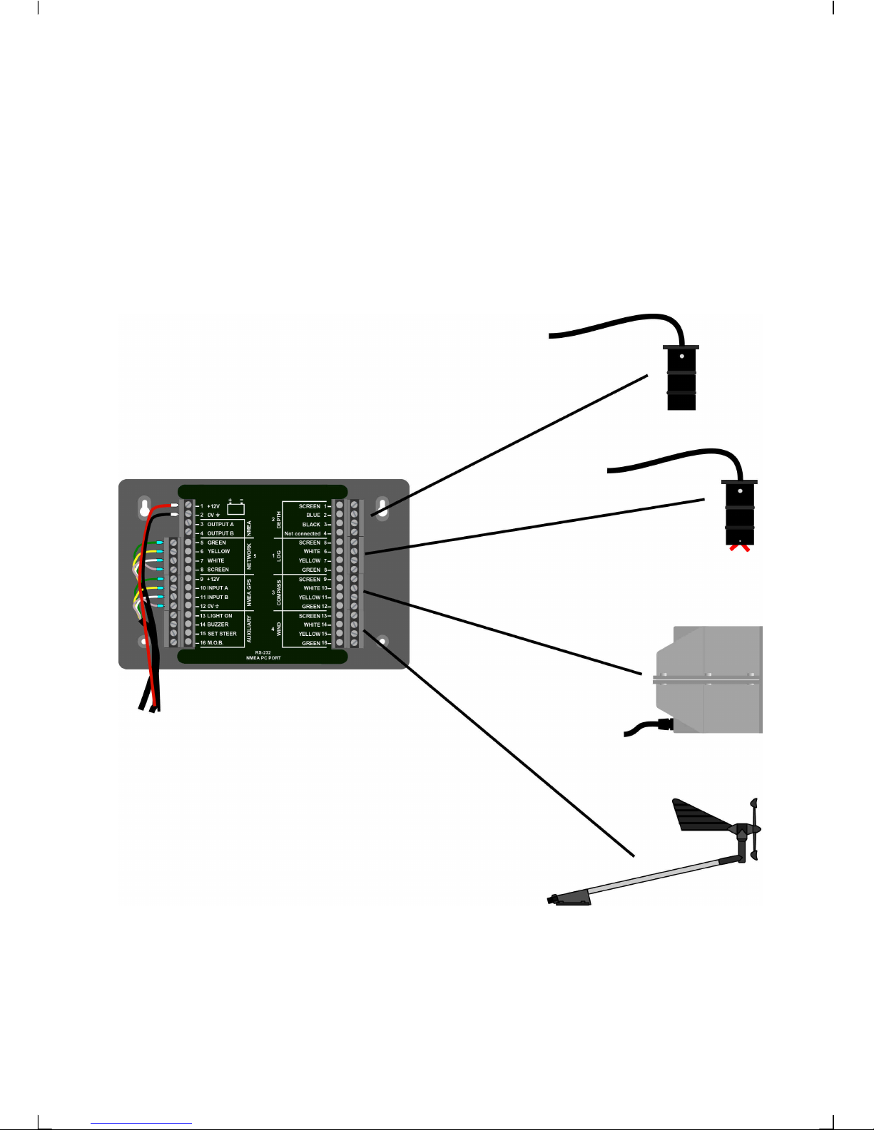
When all connections are made, use the cable straps as required. Mount the Server
cover using the 2 mounting screws.
Your Server installation is done!
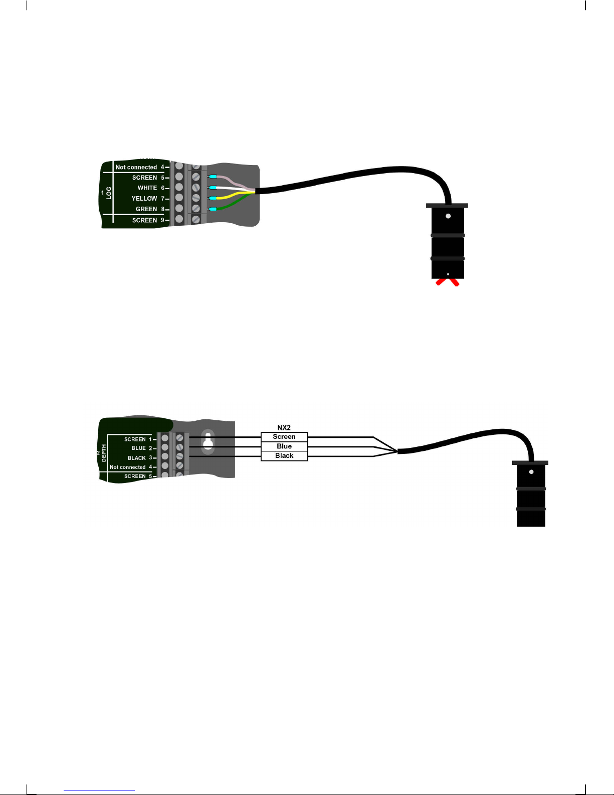
2.3 Installing the transducers
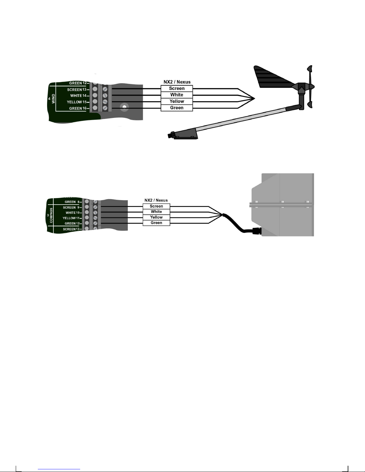
Log, depth, wind and compass transducers are all connected to the pins on the right
hand side of the Server. They are all clearly colour coded and marked with numbers
and names. Install the transducers according to the separate instructions supplied with
each transducer. Connect as per below drawings
2.4 Connecting optional accessories
These optional accessories are available from your local FURUNO Dealer. (For a more
complete list of accessories available, see 4.3).
Page 12
11
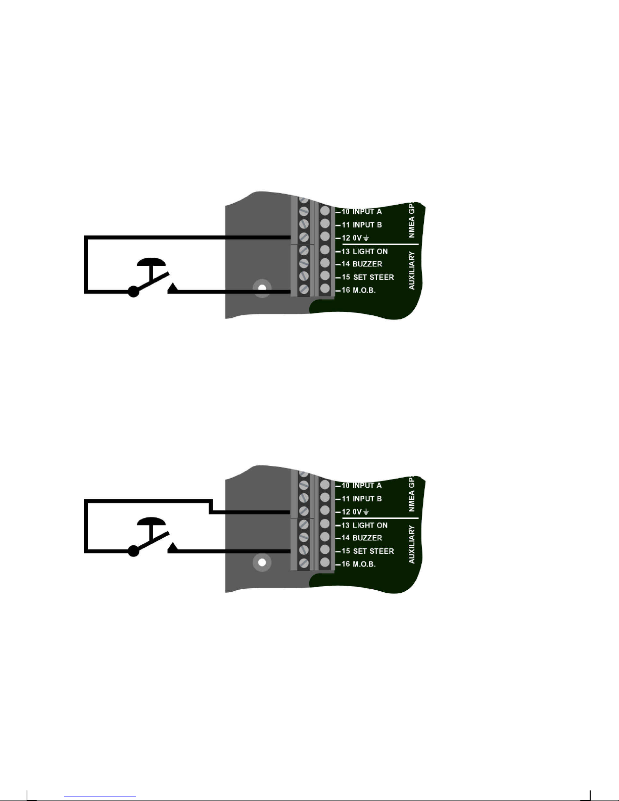
2.4.1 Man over board (MOB) push-button
White wire to Server pin 16 (MOB). Brown wire to Server pin 12 (0V).
(For function explanation, see Multi Control Manual)
2.4.2 Tactical function push-button
White wire to Server pin 15 (SET STEER). Brown wire to Server pin 12 (0 V).
(For function explanation, see Multi Control Manual)
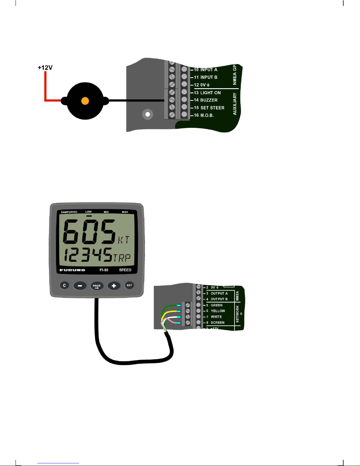
2.4.3 Extra alarm buzzer
The extra buzzer (105 dB at 15 cm, not water proof) can be mounted where you want a
louder sound. The buzzer will sound as soon as any alarm function is activated in the
Nexus Network.
Red wire to Server pin 9 (+ 12V ). Or 12V from switch panel
Black wire to Server pin 14 (BUZZER).
Page 13
12
2.4.4 FI-30 instruments
All FI-30 instruments are connected directly to the Nexus Network in a daisy chain.
They all use the same colour coded 4-pole jack plugs. (For instrument installation, see
instrument manual).
Page 14
13
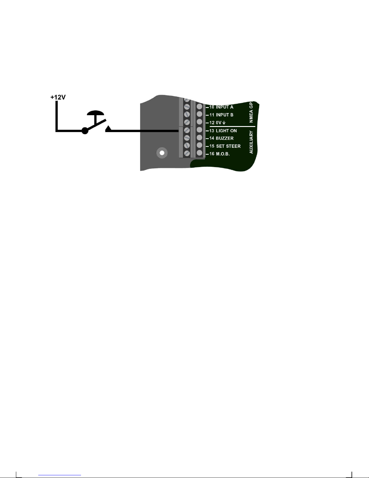
2.5 Connecting instrument lighting
The instrument lighting can be controlled from the boats general lighting switch.
Connect the wire from the electrical panels instrument light switch to Server pin 13
(LIGHT ON +12 V).
2.6 How to use the NMEA ports
The FI-30 Server is designed with two NMEA input ports and one shared output port.
The external NMEA data will be combined with FI-30 sensor data so that all
information will be available on one single output NMEA port.
One NMEA port (in/out) is dedicated for your PC and follows the RS232 electrical
standard. A 9-pole D-SUB connector is placed at the bottom of the Server.
The Other port (in/out) is accessed at the screw terminal and follows the NMEA 0183
electrical standard (RS422 out and opto-coupler input).
The two-port Server installation will solve most of the integration needs onboard, the
installation with a GPS connected to port A and the Laptop PC on port B.
1. Position, speed and course information is taken from port A (the GPS). The Server
will then pass that information plus all other boat-data to port B where the PC and
chart navigation software will calculate BTW, DTW and XTE information to the FI30 instruments, radar, auto-pilot, plotter or other source.
The NMEA ports have been given different priority's depending on the type of data that
will come into the Server when the same type of data comes on both ports.
Position and time (GPS) data GGA, GLL, GSA, GSV, RMC, ZDA have higher
priority on port A.
Navigational data (RMB, BWC, BWR, XTE, APA, APB WPL, BOD WCV ) have
higher priority on port B.
Compass
light
Page 15
14
By using this feature, you may use the PC for planning and part time navigation, then
allow for a GPS/ plotter to take over navigation without the need to change
connections.
Note!
A Laptop PC may have a GPS PCMCIA card installed and deliver position and time
data. However, if the same data is coming in on port A where position have a higher
priority, that data will be used prior to the data from the PC.
This three-port combination proposal will add several advantages. Navigation can be
made from that instrument or it can be used as a repeater, showing data from the
Laptop PC or from a GPS placed at the navigation table below deck. The GPS
instrument can be used as the primary navigator, the backup or as repeater only.
2. Position, speed and course is received from any GPS receiver. Whenever there is
a need to get use of three NMEA input ports, this is the recommended way.
Additional NMEA compass, wind-transducer or depth-sounder transmitting NMEA
can then be added.
Note!
NMEA transducers may degrade the FI-30 system performance and accuracy. For
highest performance only use FI-30 transducers.
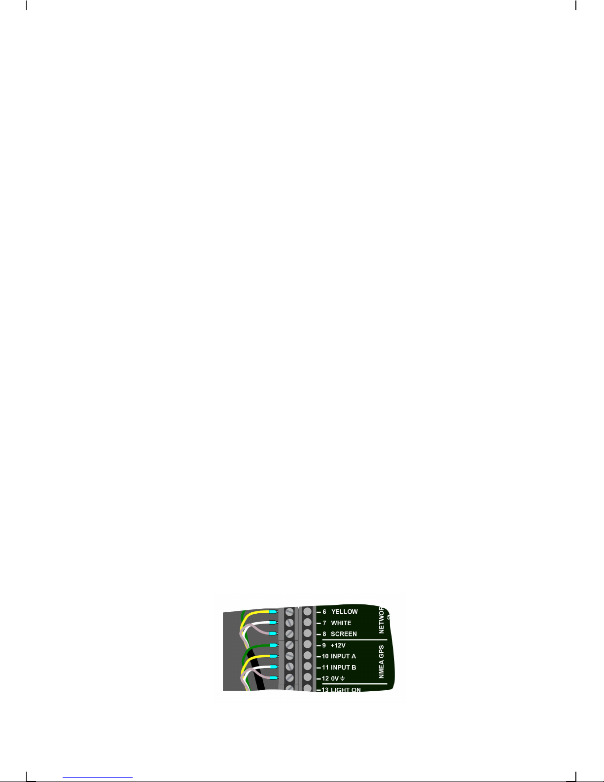
2.7 Connecting a NMEA instrument IN to the Server
Products transmitting NMEA, for example:
GPS, Decca, Loran, NMEA compass and wind transducer etc.
If a NMEA instrument is connected, most information will be available and can be
displayed on the Nexus Network.
You must know which 2 cables from your other NMEA instrument carry the NMEA out
signal. If you have trouble call the dealer you bought your NMEA instrument from. He
should know the wiring colour and will probably sell the "plug set" which may be
required. We do not have this information.
Connect NMEA out signal from the NMEA instrument to Server pin 10 (INPUT A).
Connect NMEA return signal from the NMEA instrument to Server pin 11 (INPUT B).
(For list of NMEA receive sentences, see 2.10.3).
Page 16
15
Note a: The Server allows only one NMEA instrument connected to the input pins
10 and 11.
Note b: We do not recommend the use of NMEA transducers like wind and
compass, because the update rate of data is slow compared to the very fast FI-30
data bus.
Note c: If the NMEA instrument has only one output cable, put a "bridge" cable
on the Server between pins 11 (INPUT B) and 12 (0V GND).
2.8 Connecting a NMEA instrument OUT from Server
Products receiving NMEA, for example:
Plotter, radar, Maxi repeaters, POWER Navigate.
Again you must know which 2 cables from your other NMEA instrument carry the
NMEA in signal. If you have trouble call the dealer you bought the NMEA instrument
from. He should know the wiring colour and will probably sell the "plug set" which may
be required. We do not have this information.
Connect NMEA in signal from NMEA instrument to Server pin 3 (OUTPUT A). Connect
NMEA return signal from NMEA instrument to Server pin 4 (OUTPUT B). (For list of
NMEA transmit sentences, see 2.10.1.)
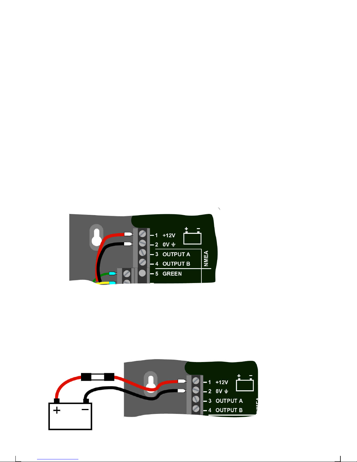
2.9 Connecting the power supply
1. Connect the red wire from the Server pin 1 (+12V) to +12V.
Connect the black wire from the Server pin 2 (0V) to 0V.
Protect the circuit with a 3 Amp fuse/circuit breaker on the 12V side.
3 A fuse
Black
Red
Page 17
16
2.10 Compatibility with our previous transducers
2.10.1 Log transducer
All our log transducers can be used for speed and distance.
Only transducers from FI-30 series are able to measure water temperature.
Note: On the Power transducer the white cable (for water temperature) should be
isolated and not installed.
2.10.2 Depth transducer
Only our depth transducers for FI-30 can be used.
Note: Do not mix with transducers from other series.
Page 18
17
2.10.3 Wind transducer
All our wind transducers can be used.
2.10.4 Compass transducer
Only the FI-30 version can be used.
Page 19

18
2.10.5 NMEA transducers
NMEA compass, NMEA wind, NMEA log and NMEA depth transducer may be used.
You must know which 2 cables from your other NMEA transducer carry the NMEA out
signal. If you have trouble call the dealer you bought your NMEA instrument from. He
should know the wiring colour and will probably sell the ”plug set” which may be
required. We do not have this information.
Connect NMEA out signal from the NMEA transducer to Server pin 10 (INPUT A).
Connect NMEA return signal from the NMEA transducer to Server pin 11 (INPUT B).
Note a: The Server allows only one NMEA transducer or instrument connected to
the input pins 10 and 11.
Note b: Make sure the calibration codes C73, C74, C75 and C76 (See Multi
Control Manual) for NMEA transducers are correctly set.
Page 20

19
2.11 NMEA
2.11.1 Transmit NMEA sentences OUT from Server
Calibration code C77 to C92 contains 16 NMEA slots
The Server supports 29 different NMEA sentences.
This means you can select up to 16 of the 29 available NMEA sentences.
The Nexus Network uses the NMEA 0183 sentences, version 1.5 and 2.0. The number
in brackets, example (C79), is the calibration code for the factory slot number given to
the NMEA sentence.
0 ( — ) No out signal
1 (APB) Autopilot B
2 (BOD) Bearing original destination
3 (BWC) Bearing and distance to waypoint
4 (BWR) Bearing and distance, dead reckoning
5 (C77) (DBT) Depth measured from the transducer position
6 (DPT) Depth
7 (C78) (GLL) Geographic position
8 (GSA) DOP and active satellites
9 (C79) (GSV) Satellites in view
10 (C80) (HDM) Compass heading, magnetic.
11 (C81,89) (HDT) True heading
12 (MTW) Water temperature
13 (C82) (MWD) Wind direction and speed
14 (C88) (MWV) Apparent wind speed and angle
15 (RMB) Minimum navigation data
16 (RMC) Minimum specific GPS- and TRANSIT-data
17 (C87) (RSA) Rudder Sensor Angle
18 (RTE) Route Not implemented
19 (C83) (VDR) Set and drift
20 (C84) (VHW) Speed and course through the water
21 (VLW) Distance travelled through the water
22 (C85) (VPW) Speed relative to the wind
23 (C86) (VTG) Course Over Ground and Ground Speed.
24 (VWT) True wind speed and direction
25 (C90) (WCV) Waypoint closure velocity
26 (WPL) Waypoint location Not implemented
27 (C91) (XTE) Cross track error
28 (C92) (ZDA) Time and date
29 (ZTG) & (UTC) Time to destination or waypoint
Example of NMEA sentences:
$IIAPA,A,A,00.007,L,N,V,V,145.03,M,004
$IIAPB,A,A,00.007,L,N,V,V,147.53,T,004,147.52,T,,T*29
$IIBOD,147.53,T,145.03,M,004,000
$IIBWC,101515,5912.890,N,01812.580,E,147.52,T,145.02,M,15.649,N,004
$IIBWC,,,,,,147.52,T,145.02,M,15.647,N,004
Page 21

20
$IIBWR,101516,5912.890,N,01812.580,E,147.52,T,145.02,M,15.647,N,004
$IIDBT,293.52,f,089.47,M,048.36,F
$IIDPT,089.47,0.40
$IIGLL,5926.110,N,01756.171,E,101517,A
$IIHDM,026,M
$IIHDT,029,T
$IIMTW,19,C
$IIMWD,161.77,T,159.27,M,07.01,N,03.61,M
$IIMWV,133,R,07.03,N,A
$IIRMA,A,5926.110,N,01756.171,E,,,0.23,189.47,,,,*00
$IIRMB,A,00.007,L,000,004,5912.890,N,01812.580,E,15.647,147.52,,V*01
$IIRMC,101340,A,5926.115,N,01756.172,E,0.04,063.42,,,*06
$IIVDR,063.42,T,060.92,M,0.04,N
$IIVHW,029,T,026,M,00.00,N,00.00,K
$IIVLW,49626.59,N,,
$IIVPW,0.00,N,,
$IIVTG,063.42,T,060.93,M,0.04,N,,
$IIVWR,133,R,07.03,N,03.62,M,,
$IIVWT,133,R,07.01,N,03.61,M,,
$IIWCV,0.00,N,004
$IIWPL,5503.000,N,01013.450,E,027
$IIXTE,A,A,00.003,L,N
$IIZDA,101341,,,,
$IIZTG,101341,,004
2.11.2 Change NMEA sentences OUT from Server
Before you change any of the factory set NMEA sentences, check what NMEA
sentences can be received by your NMEA navigator.
Select the slot number for the sentence to be changed, then press SET.
To select the sentence, press MINUS or PLUS until found.
To lock the selected sentence, press SET.
One of the advantages with the Nexus Network is the very fast transmission speed of
data compared to the relatively slow NMEA standard (about 10 times faster). Therefore
we recommend that you use FI-30 instruments and transducers for better accuracy.
It takes two seconds to transmit all 16 NMEA sentences.
To double the transmission speed, select a NMEA sentence 2 times with 7 slots apart,
that is the slots should be as far away from each other as possible.
In a similar way, you can select the a sentence 4 times to make it 4 times faster.
Example: If you want to transmit the FI-30 compass heading via NMEA, to for example
an autopilot, select (HDM) for every odd slot number, C79, C81, C83 ... C93, that is 8
times which makes the speed 4 times / second. This leaves the other 8 slots with even
numbers, C78, C80, C82 ... C92 free to use for other NMEA sentences.
For connection of NMEA instruments OUT from Server, (see 2.8).
Page 22

21
2.11.3 Receive NMEA sentences IN to Server
There are 6 different main types of NMEA sentences:
1) Position related data: Position, SOG/COG, time, and a limited amount of satellite
status if a GPS is connected.
2) Navigation data: (BTW), (DTW), (BOD), (XTE), (SET) and (DRIFT).
The Server will automatically send data to the Nexus Network. E.g.: (DRIFT), (WCV),
(TTG) and (CTS).
3) Speed data: is read only if (C73 BSP) is set to (ON). See Multi Control Manual
4) Depth data: is read only if (C74 DEP) is set to (ON). See Multi Control Manual
5) Compass data: is read only if (C75 CMP) is set to (ON). Heading is either (HDT)
(priority) or (HDM). Magnetic variation (from Nexus Network) is added to (HDM) but not
to (HDT). See Multi Control Manual
6) Wind data: angle and wind speed is read from (MWV) data, only if (C76 WND) is
set to (ON). True wind angle and wind speed is calculated by FI-30, when the boat
speed (the speed of the water) is known.
The following NMEA sentences can be received IN to Server:
APA Autopilot sentence ”A”
APB Autopilot sentence ”B”
BOD Bearing original destination
BWC Bearing and distance to waypoint
BWR Bearing and distance to waypoint (old)
DBT Depth measured from the transducer position
DPT Depth
GGA Global positions fix data (GPS)
GLL Geographic position, Latitude/Longitude
GSA DOP and active satellites
GSV Satellites in view
HDM Heading, magnetic
HDT Heading, true
MTW Water temperature
RMB Minimum navigation information
RMC Minimum specific GPS/transit data
WCV Waypoint closure velocity
VDR Set & drift
VHW Water speed and heading
MWV Wind speed and direction
VTG Course Over Ground and Ground Speed
XTE Cross-track-error, measured
ZDA Time & date
TBS Target boat speed
CAD Custom angular data
CFD Custom fix data
RSA Rudder Sensor Angle
Page 23
22
For connection of NMEA instrument IN to Server, (see 2.7)
All data (POSITION, BTW, SOG/COG, etc.) is received from one type of NMEA
sentence. If data is placed in different locations, the data will be selected from the
sentence with the highest priority.
Example I: Position is read in priority order: GGA, GLL and. RMC.
Example II: BTW/DTW is priority first with: RMB, BWC and BWR.
The transmission ID (the first two letters after “$”) is ignored by the Server. Present
position is read, after that possible latitude and longitude correction is added (C39 and
C40) before the position is sent over the Nexus Network to all instruments
2.12 Special NMEA sentences
The Server can read 2 special NMEA sentences which can be send from a PC. One
contains TBS (target boat speed), the other CAD (customised angle data ) and CFD
(customised fixpoint data ). These 3 data are retransmitted on the Nexus Network and
can be displayed as a sub-function on the Multi Control instrument.
To get the sub-function TBS, select main function SPEED and the ”empty” subfunction.Then press PAGE and SET together followed by CLEAR.
To get the sub-function CAD, select main function NAVIGATE and the ”empty” subfunction.Then press PAGE and SET together followed by CLEAR.
To get the sub-function CFD, select main function WIND and the ”empty” subfunction.Then press PAGE and SET together followed by CLEAR.
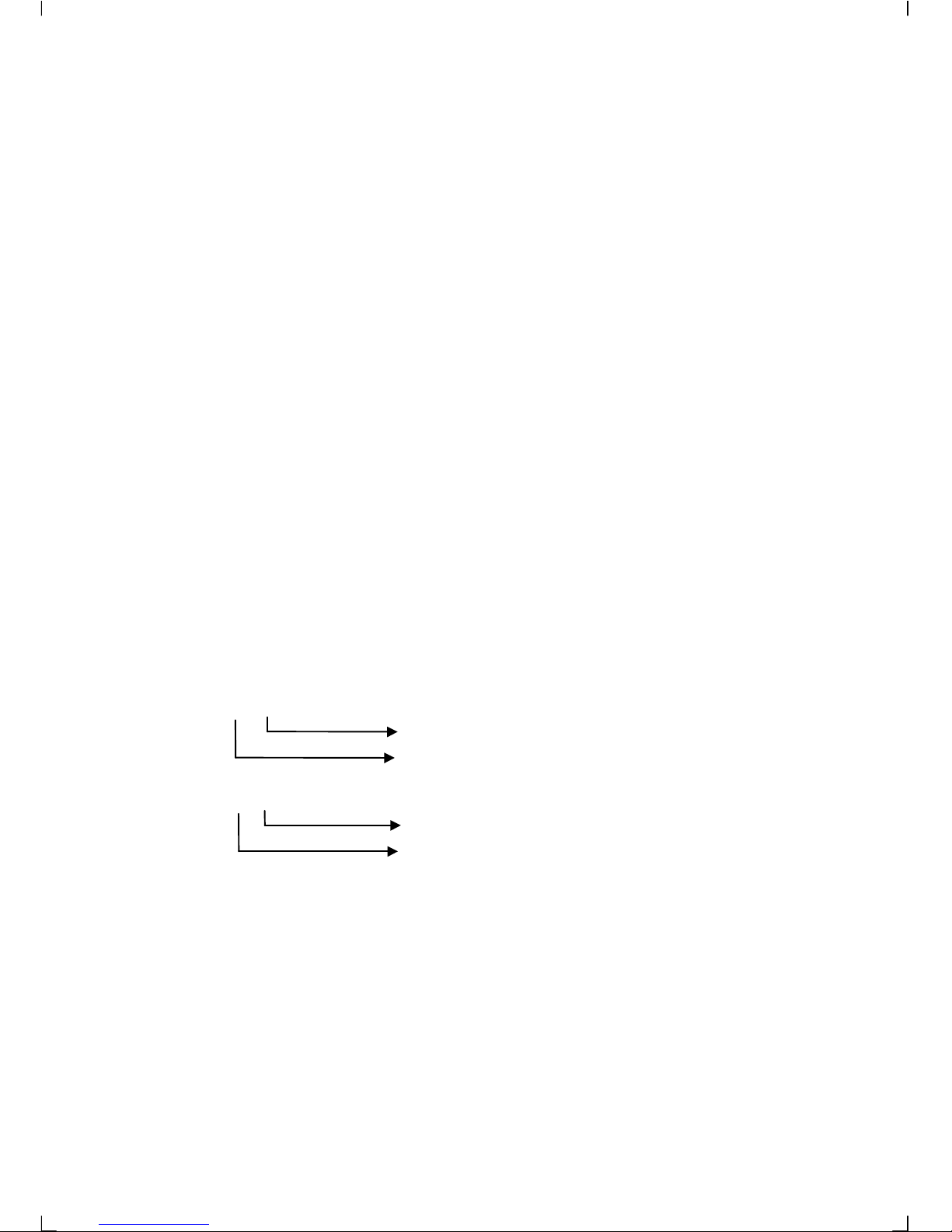
Example of special NMEA-sentence:
$PSILTBS,X.X,N<CR><LF>
Knots
Target boat speed
$PSILCD1,X.X,X.X,<CR><LF>
CAD (000.0°-360.0°)
CFD (-327.67- +327.67 units)
Baudrate control,
It is possible to change the baudrate from 4800bps to 19200bps. To do that, a PC is
required. Note 19200 is not to be considered as NMEA since the standard states 4800.
a. The Requesting unit is allowed to transmit the message:
"$PSILBPS,19200,R,<CR><LF>"
once every 2s at nominal 4800 bps with normal NMEA start bit and stop bit settings.
This message may be received on any of the two Server ports.
Page 24

23
b. The receiving unit (FI-30 Server) will Confirm message:
"$PSILBPS,19200,C,<CR><LF>"
and send it back on output ports to the requesting unit.
c. When the requesting unit receives the same message but with the flag set to "C"
(Confirmed), both server ports (A and B) are set to 19200bps and transmission may
start at the new baudrate. The sending unit may now stop sending the proprietary
request message since it has entered the higher baudrate. There is no way back
unless there is a power loss.
From power up, baudrate is always set to 4800 and the above procedure must be
repeated.
The receiving unit (FI-30 Server) will always check for the proprietary message when in
normal baudrate, not when in high baudrate.
Page 25

24
3 Maintenance and fault finding
3.1 Maintenance
• To clean the instrument, use only mild soap solution and rinse with water.
• Do not use detergents or high pressure washing equipment.
• At least once a year, check all your connections and apply additional
silicon paste at each connection point.
• Always use the instrument cover for protection, when not in use.
• Storing transducers and instruments when not in use for longer periods: It is
advisable to remove the instruments and transducers, and store them inside the
boat or at home in room temperature, if possible.
3.2 Fault finding
Before you contact your FURUNO dealer, and to assist your dealer to give you a better
service, please check the following points and make a list of:
• All connected instrument and transducers , including their software version
numbers.
• Server software version number.
• Nexus Network data bus ID numbers for each instrument (displayed at power up).
3.2.1 General
In most cases, the reason for faults in electronic equipment is the installation or poor
connections. Therefore, always first check that:
• Installation and connection is made per instructions for instrument and
transducers, (see 3).
• Screw terminals are carefully tightened.
• No corrosion on any connection points.
• No loose ends in the wires causing short cuts to adjacent wires.
• Cables for damage, that no cables are squeezed or worn.
• Battery voltage is sufficient, should be at least 10V DC.
• The fuse is not blown and the circuit-breaker has not opened.
• The fuse is of the right type.
• Two instruments do not have the same ID number, (see Multi Control Manual).
Page 26
25
3.2.2 Fault - action
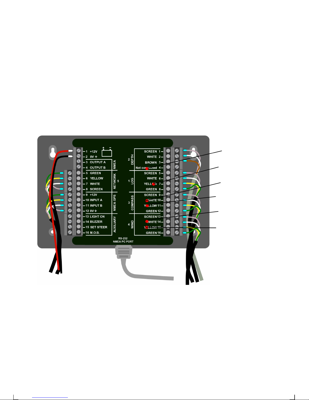
1. Speed and distance functions: No reading ( --- )
− C95 (COG) should be OFF, if no navigator is connected.
The server is equipped with a built in fault finding LED. Every turn the paddle wheel
takes the LED flashes once. When the boat is standing still the LED is either on or off.
If you remove the transducer and slowly spin the paddle wheel the LED should go on
and off.
When the boat is running the LED is flashing.
If the LED is constantly on or of, check the connections.
Irregular values: Check the speed damping (SEA), (see Instrument manual).
2. Compass: No reading ( --- )
− C94 should be OFF, otherwise, COG is displayed instead of HDC.
− C75 should be OFF, if no NMEA compass is connected.
− Make sure the (Auto DEV) routine is done correctly, (see instrument
manual)
− Make sure the transducer is not mounted upside down.
− The transducer cable should face down.
− Make sure transducer is aligned correctly, (see instrument manual).
Depth echo
Compass A
Compass B
Wind A
Wind B
LOG pulses
Page 27

26
With the built in fault finding LED’s, you can check that the signals from channel A and
B are correct. The LED is flashing very fast with 13HZ (13 times per second) which is
difficult to see but you will see that the LED is not on constantly. If one or both LED are
on or off all the time, check the connections.
Irregular values: Check the compass damping (see instrument manual),
Make sure there are no ferrous items close to the transducer.
3. Wind: No reading ( --- )
− C76 should be OFF, if no NMEA wind is connected.
− If inaccurate wind data is received, check the connections (separate
through deck connection or below decks connection), are properly made.
− With the built in fault finding LED’s, you can check that the signals from
channel A and B are correct. The two LED are flashing once every turn
the propeller makes. If the wind speed is high, the flashing is very fast
which is difficult to see but you will see that the LED is not on constantly.
− If one or both LED are on or off all the time, check the connections.
4. What you should know about digital depth sounders.
The principle of a depth sounder is that you measure the time it takes for a short
acoustic signal to go from the transducer to bottom and back again to the transducer.
The echo changes due to bottom character, heavy layers of salt and temperature,
irregular bottom vegetation, fish etc. Thanks to an advanced signal treatment, these
variations will normally not influence the depth measurement.
You can in some circumstances get transitory disturbances.
Below are listed some explanations for disturbances to the measurement of depth and
how it is expressed on the instrument display.
1. There is no depth reading on the display. Only ( --- ) is displayed:
If there are no depth echoes for 3 seconds, the display indicates 3 dotted lines ( --- )
until a new echo is received.
• In deep water outside the range of the transducer, or the combination of deep
water and soft bottom which makes it difficult to reflect the signal.
• When the boat is heeling heavily, for example when sailing.
• In a propeller stream, where air bubbles are created. Example when powering
astern or when following close behind a power boat.
• Check the connection at the Server. Make sure the cable is correct between,
instrument and transducer, as marked on the Server.
• Internal mount with poor signal penetration due to a too thick hull, (maximum
thickness recommended is 20 - 30 mm) or air between transducer and hull.
The built in fault finding LED is flashing every time a echo is received to the server.
The depth sounder is transmitting three times per second and the LED flashes 3
times/sec if everything is correct.
Page 28

27
If the LED is constantly off, check the connections. Or the mounting of the transducer.
2. Unstable or erratic readings. Can happen in the following cases:
• When going over shoal water, with uneven and high bottom vegetation.
• In heavy layers of salt or noticeable ranges of water temperatures.
• In heavily agitated water containing particles of sand or some other contamination.
The bottom of the transducer may be painted with anti fouling for protection against
weed growth. It is recommended the transducer is cleaned at regular intervals
depending on what kind of waters you boat in.
Weed on the transducer can cause either no reading or unstable readings.
In general when a boat is moored in a harbour with other boats around, there can be
disturbances from signals from other depth transducers, chains or other mooring
equipment, which will result in wrong depth readings.
3.2.3 Error messages
The following error messages can appear on the display:
ERROR 2 Nexus Network is missing, check colour coded connections
ERROR 3 No data received within a given time.
ERROR 10 Range error caused by bad format e.g. 17° 70' East.
ERROR 11 Remote command that can not be performed.
ERROR 12 No response from, or missing navigator.
ERROR 13 Waypoint not defined.
ERROR 15 Functions not allowed in autopilot mode.
ERROR 16 Automatic deviation not possible due to NMEA compass selected.
ERROR 17 Automatic deviation check failed. Turn not completed, error larger
than 1.5°.
ERROR 19 The boat probably hit a wave during turn. Error larger than 1.5°.
If other error messages than the above appears on the Multi Control instrument,
contact your FURUNO dealer.
Page 29

28
4 Specifications
4.1 Technical specifications
Dimensions: Server: 110 x 165 x 30 mm. (4.3x6.5x1.2 inch)
Instrument cable: 8 m (26 ft).
Power supply: 12V DC (10-16V). The instruments are polarity protected
Power
consumption at 12V: Server: 0.2W.
Temperature range: Storage:-30°to +80°C (-22°to +176°F)
Operation: -10° to +70°C(14°to +158°F)
Weight: 220 gram. (7.76 oz).
Enclousure: Splash proof
CE approval
The products conforms to the EMC requirements for immunity and emission according
to EN 50 08-1.
4.2 FI-30 databus introduction and user policy
Introduction:
The FI-30 data bus is a multi talker multi receiver data bus specially designed for
marine navigation applications. It utilises the RS485 standard with up to 32 senders
and/or receivers to form a Local Area Network. Data is transmitted synchronously with
1 start-bit, 8-data-bits, 1 parity-bit, two stop-bits in 9600 baud.
User policy:
The FI-30 data bus is open for new users and applications without the a licence or a
licence fee. The data bus is, however, the property of the manufacturer, which means
the specification must be followed in order to protect the manufacturer’s commitments
to the FI-30 data bus performance and safety.
For most PC-applications, the full duplex interface, will be a very useful tool for
monitoring real time data, to edit and store waypoints to PC-file or to Server. The
interface is supplied with a cable for connection from PC to the Server or FI-30
instruments. A 9-pole D-sub connector is connected to the RS232 port on the PC.
Page 30
29
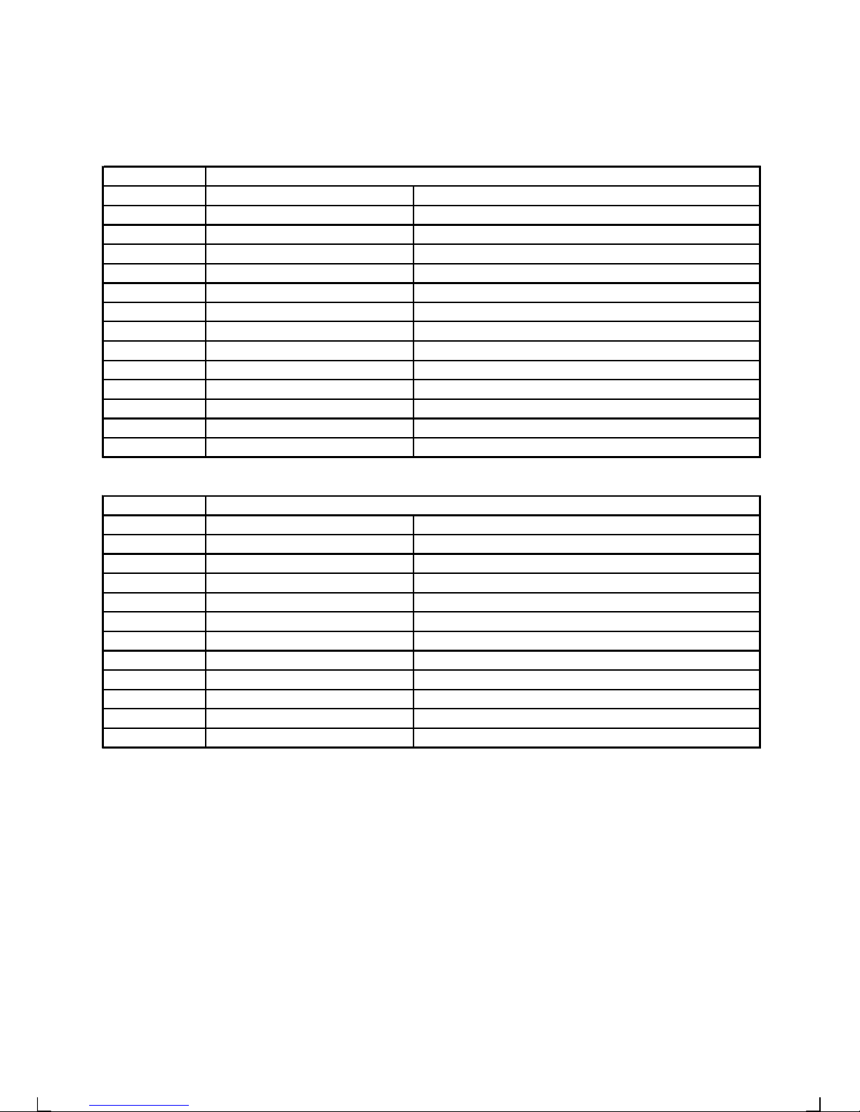
4.3 Equipment Lists
INSTRUMENT SERIES
PART #
MODEL
000-041-864
FI-301
MULTI CONTROL
000-041-865
FI-301-SERVER
MULTI CONTROL W/SERVER
000-041-866
FI-301-SERVER/SENSOR
MULTI CONTROL W/SERVER & SENSORS
000-041-867
FI-302
SPEED
000-041-868
FI-302-SENSOR
SPEED W/ST SENSOR
000-041-869
FI-303
WIND DATA
000-041-870
FI-303-SENSOR
WIND DATA W/WIND SENSOR
000-041-871
FI-304
COMPASS DATA
000-041-872
FI-305
MULTI XL
000-041-873
FI-306
ANALOG WIND ANGLE
000-041-874
FI-307
STEER PILOT
000-041-875
FI-308
SPEED TRIM
000-041-876
FI-309
RUDDER ANGLE
000-041-877
FI-310
ANALOG COMPASS
ACCESSORIES
PART #
MODEL
000-041-878
FI-3001-DEPTH
DEPTH TRANSDUCER
000-041-879
FI-3002-LOG
ST SENSOR
000-041-880
FI-3003-WIND
WIND SENSOR
000-041-881
FI-3004-COMPASS
FLUXGATE COMPASS
000-041-882
FI-3005-SERVER
SERVER
000-041-883
FI-3006-DEMO-SERVER
SERVER SIMULATOR
000-147-005
FI-3007-BUZZER
EXTERNAL ALARM BUZZER
000-147-006
FI-3008-MOB
MOB BUTTON
000-147-007
FI-3009-CABLE-100M
INTERCONNECTION CABLE 100M
000-147-008
FI-3010-CABLE-8M
INTERCONNECTION CABLE 8M
000-147-030
FI-3011-CABLE-0.3M
INTERCONNECTION CABLE 0.3M
000-147-041
FI-3014-MASTCABLE-25M
WIND MAST CABLE 25M
Page 31

30
Page 32

31
22348-1 Edidtion 2
 Loading...