

Page 1

Page 2

(
C
9-52, Ashihara-cho,
Nishinomiya, Japan
Telephone: 0798-65-2111
Telefax: 0798-65-4200
All rights reserved.
Printed in Japan
Your Local Agent/Dealer
FIRST EDITION : AUG. 1995
M : JUL. 3, 2001
PUB. No. IME-34070-M
TENI)
FAR/FR-2835S
Page 3

Page 4
Page 5

TABLE OF CONTENTS
EQUIPMENT LISTS............................................................................ v
1. MOUNTING
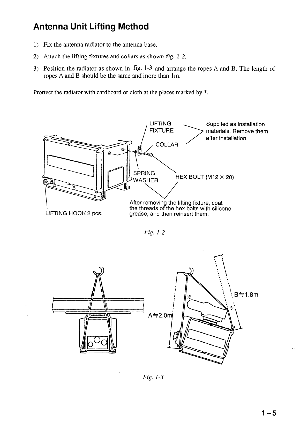
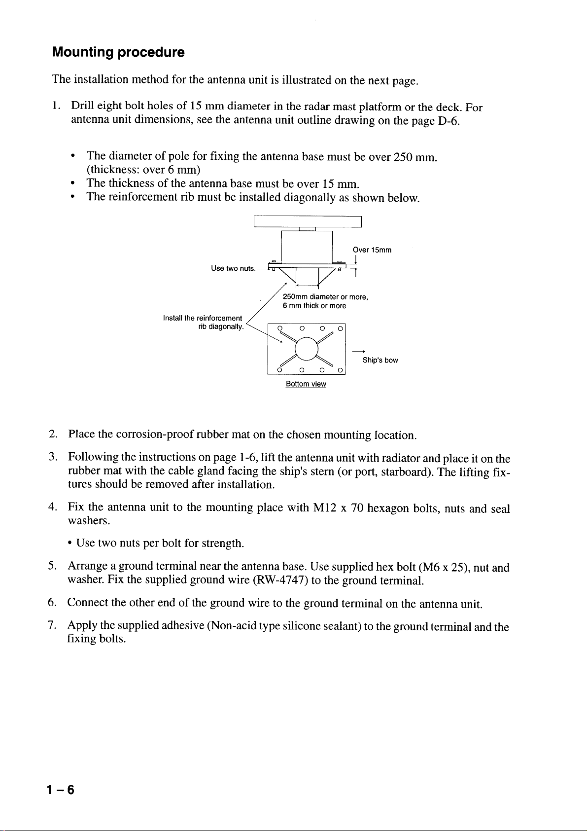
1.1 Radiator Assembling Procedure ......................................................................................1-1
1.2 Mounting Structures ........................................................................................................1-3
1.3 Mounting the Antenna Unit on the Mounting Platform...................................................1-4
1.4 Mounting the Display Unit ..............................................................................................1-8
1.5 Mounting the Separate Type Control Panel .....................................................................1-9
2. CONNECTIONS
2.1 Antenna Unit Connections ...............................................................................................2-1
2.2 Display Unit Connections................................................................................................2-6
2.3 Changing Power Specifications.....................................................................................2-13
2.4 Power Supply Unit.........................................................................................................2-14
3. INITIALIZATION AND ADJUSTMENT
3.1 Menus for Initialization and Adjustment .........................................................................3-1
3.2 Heading Alignment ..........................................................................................................3-2
3.3 Adjusting Sweep Timing .................................................................................................3-2
3.4 Adjusting Video Signal Level..........................................................................................3-3
3.5 Suppressing Main Bang...................................................................................................3-4
3.6 Confirming Tuning ..........................................................................................................3-4
3.7 Confirming Magnetron Heater Voltage ...........................................................................3-5
3.8 Initial Settings Menus ......................................................................................................3-6
3.9 Setting the Function Keys................................................................................................3-8
3.10 Default of InitialSetting Menus ...................................................................................3-11
3.11 How to adjust ARP board ............................................................................................3-12
3.12 Installation Check List.................................................................................................3-14
4. INSTALLATION OF GYRO CONVERTER GC-8 (option)
4.1 General Procedure for Installing and Setting up the GYRO CONVERTER Board ........4-1
4.2 Connection of External Power Supply ............................................................................4-3
4.3 Confirming Gyrocompass Specifications ........................................................................4-3
4.4 Changing Settings on the GYRO CONVERTER Board .................................................4-4
4.5 Setting the Bearing on the Radar Display........................................................................4-8
iii
Page 6

LIST OF INSTALLATION MATERIALS, ACCESSORIES AND
SPARE PARTS
LIST OF INSTALLATION MATERIALS, ACCESSORIES AND SPARE PARTS
......................................................... L-1 to L-13
OUTLINE DRAWINGS
OUTLINE DRAWINGS........................................................................................... D-1 to D-6
SCHEMATIC DIAGRAMS
SCHEMATIC DIAGRAMS .......................................................................................S-1 to S-6
iv
Page 7

Complete set
.oNemaNepyTytQskrameR
1tinurennacSFA63-NS1rotaidarannetnA
FA03-NS
6200-BSR1tinurennacS
1300-BSR
8800-BSRCSHroftinurennacS
9800-BSR
0900-BSR
2tinuyalpsiD511-PDR1 epyttnuomlatsedeP
EQUIPMENT LISTS
epytpotelbaT
3seirosseccA01750-30PFtes1,10750-30-PF,tinulortnocni-tliubroF
1181
03750-30PF,10750-30-PF,tinulortnocetarapesroF
4slairetamnoitallatsnI30641-30PCtes1tinurennacsroF
20641-30PCtes1tinuyalpsidroF
70931-30PCtes1tinuylppusrewoproF
5elbaclangiS*m51*5986-WR1
*m02*5986-WR
*m03*5986-WR
*m06*5986-WR
6straperapS00611-30PStes110311-30PS,02301-30PS
7tinUylppuSrewoPS-32-07-400-USP1 A3.2,CAV002/002,ø3
S-01-08-400-USPA0.1,CAV044/083,ø3
-331-30,50750-30-PF,40750-30-PF
-30-PF,40750-30-PF,30750-30-PF
1181-331-30,50750
v
Page 8

Optional equipment
.oNemaNepyT.oNedoCskrameR
1spirgdnaH07-30PO024-324-800tinuyalpsidroF
2etalpgnixifdracM331-30PO004-254-800
3dooH4750-30PF018-954-800
4revoctinuyalpsiD621-30PO028-954-800tinulortnocni-tliub/wpotelbaT
721-30PO067-954-800tinulortnocetarapes/wpotelbaT
821-30PO098-954-800tnuomlatsedeP
5tinuyalpsiD
tiknoisrevnoc
6lenaplortnoC
etalpgnixif
7rettolpoediV52-PR
8retrevnocoryG2-8-CG025-644-800slairetamnoitallatsnihtiW
9hctiwsretnI7-JR
01rezzublanretxE12-30PO790-030-000rotcennochtiw,m1
11ecnamrofreP
rotinom
21tinuegnaR
tiknoisrevnoc
1-921-30PO038-954-800ni-tliub/epytpotelbatmorfstrevnoC
2-921-30PO014-254-800
1-031-30PO009-954-800etarapes/epytpotelbatmorfstrevnoC
2-031-30PO034-254-800
131-30PO019-954-800potelbatottnuomlatsedepmorfstrevnoC
1-231-30PO029-954-800potelbatottnuomlatsedepmorfstrevnoC
2-231-30PO054-254-800
431-30PO043-164-800ottinulortnocepytetarapesgninetsafroF
05-MP
1-011-30PO016-644-800mkoT
tnuomlatsedepottinulortnoc
tnuomlatsedepottinulortnoc
tinulortnocni-tliub/epyt
tinulortnocetarapes/epyt
potelbata
31tinuegnaR
tiknoisrevnoc
41tinuyalpsidroloC141-DC
51tinuyalpsidevalS0008-DMF
61tinuremrofsnarT8571-UR614-030-000CAV001otCAV022strevnoC
71tinuremrofsnarT3081-UR024-030-000CAV001otCAV044strevnoC
81hctiwsretnI8-JR
91tinuecafretnI0032-FI224-200-000
2-011-30PO002-254-800msoT
vi
Page 9
PM-50
250V-DPYC(Y)-1.25
115/230 VAC, 1φ
Optional Supply
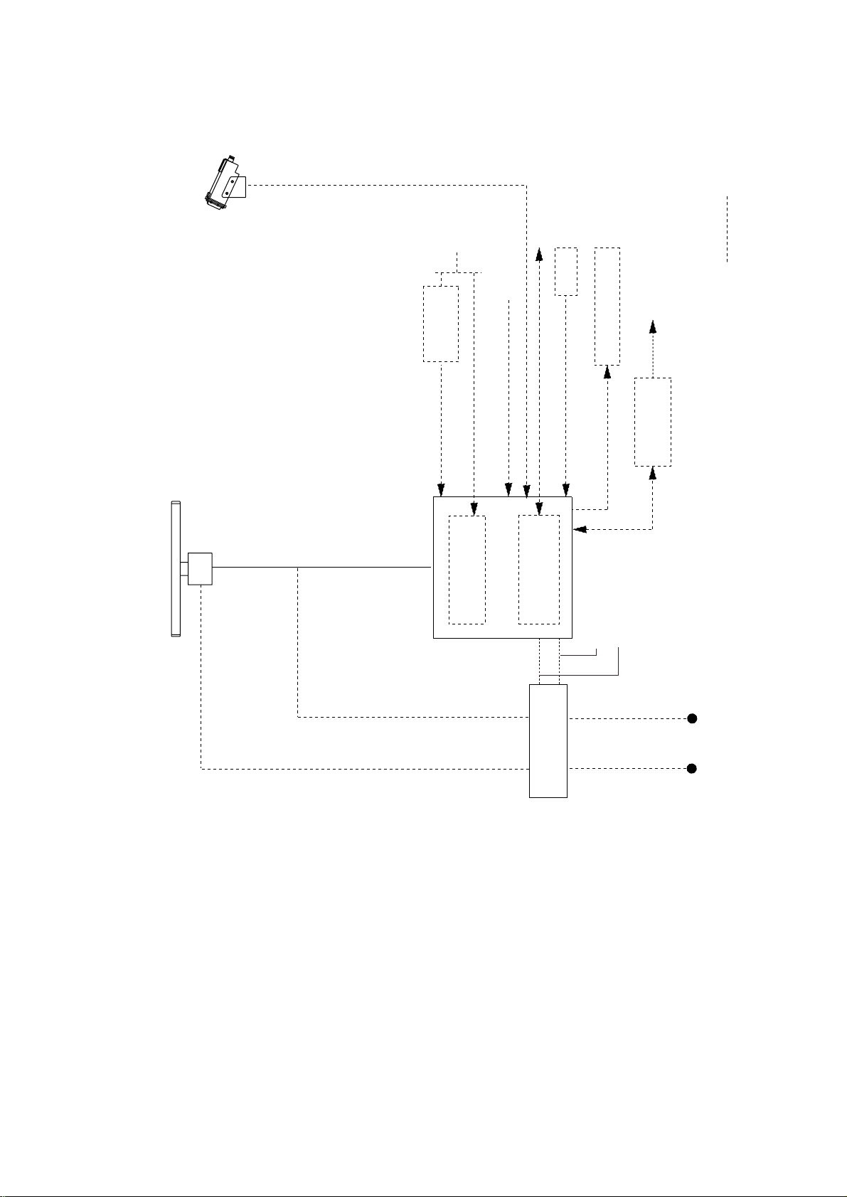
Performance Monitor (option)
SCANNER ANTENNA
RSB-0026/0031
RSB-0088/0089/090 (For HSC)
RW-6895
Gyro Converter
CO-SPEVV-SB-C
DISPLAY UNIT
Gyro
Speed Log
250V-DPYC(Y)-1.25
250V-MPYC(Y)-5
Gyro Interface GC-8
INS
NAV
External Buzzer
CO-SPEVV-SB-C
Video Protter RP-25
2C 1.5 m
250V-DPYC(Y)-3.5
Other Radar
system
RJ-7/8
Interswitch
250V-MPYC(Y)-5
FR/FAR-2835S System Configuration
250V-DPYC(Y)-3.5
Power Supply
PSU-004
250V-DPYC(Y)-3.5
For display unit
Display unit
115/230 VAC, 1φ
660V-TPYC(Y)-3.5
250V-TPYC(Y)-3.5
For scanner unit
380 VAC, 3φ, 50 Hz
440 VAC, 3φ, 60 Hz
(For HSC)
Scanner unit
220 VAC, 3φ, 50 Hz
220 VAC, 3φ, 60 Hz
220 VAC, 3φ, 50 Hz
220 VAC, 3φ, 60 Hz
440 VAC, 3φ, 60 Hz
vii
Page 10

Page 11

Page 12

Page 13
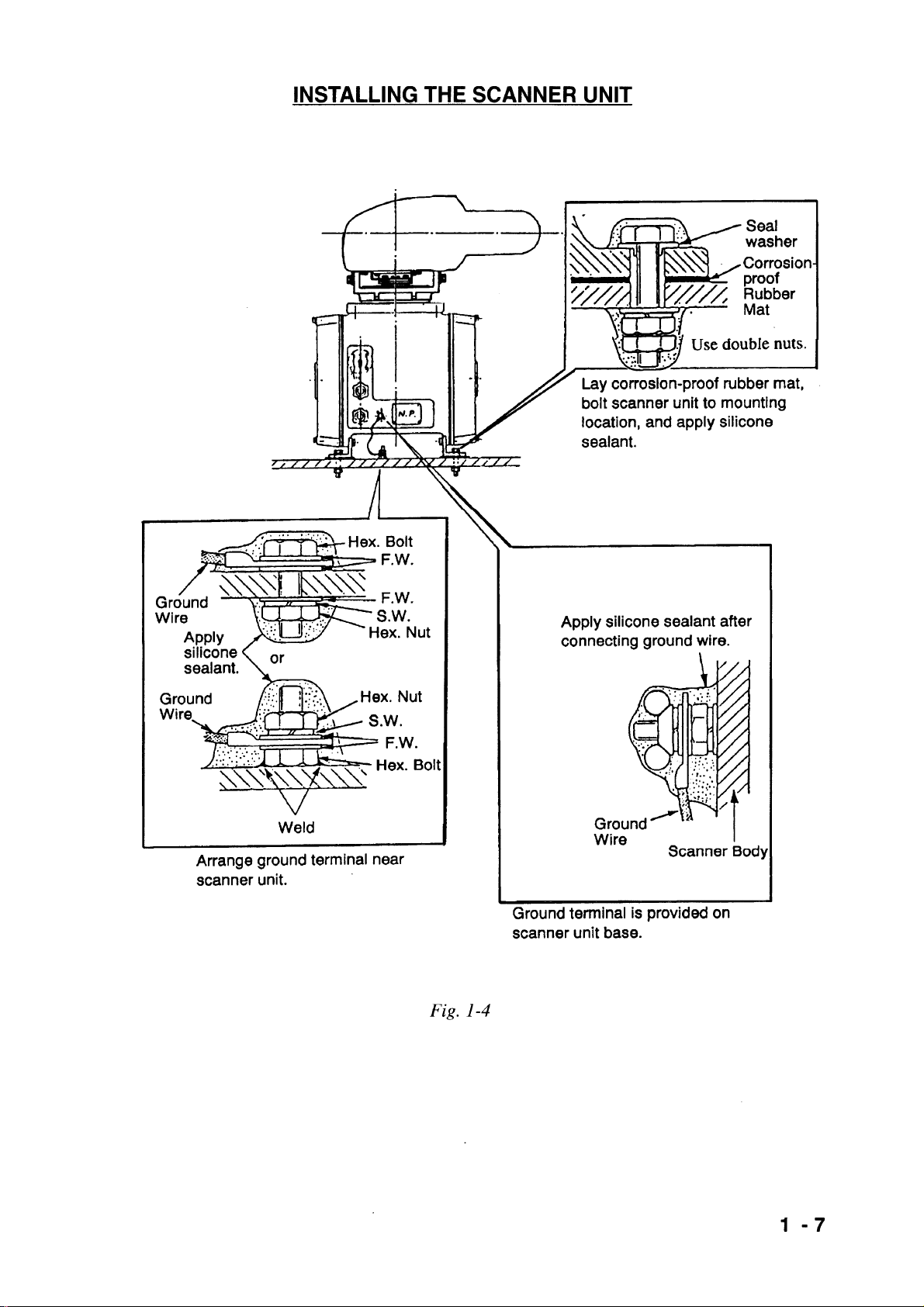
1.3 Mounting the Antenna Unit on the Mounting Platform
CAUTION
1) Work at high places is dangerous. Always wear a
hard hat and safety belt when working on the
antenna unit mast.
2) Both a service platform and steps to the service
platform must be mounted to provide safe access
for service personnel. Improperly installed
platforms present a hazard to service personnel.
Siting considerations
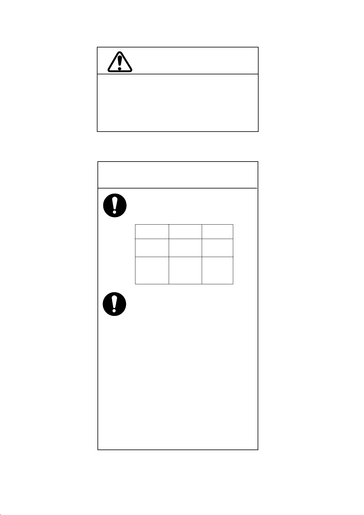
CAUTION
A magnetic compass will be affected if
placed too close to the antenna unit.
Below are the minimum safe distances
for magnetic cpmpassis.
Antenna
RSB-0026
RSB-0031
Standard
Compass
4.8 m
Steering
Compass
3.6 m
RSB-0088
RSB-0089
RSB-0090
Consider the following points when selecting
a mounting location for the antenna unit.
¥ No funnel, mast or derrick should be within
the vertical, beam width of the antenna in
the bow direction, especially zero degrees
–5°, to prevent blind sectors and false
echoes on the radar picture.
¥ Fumes from the funnel or other exhaust
vent can adversely affect performance and
hot gas can distort the radiator. The antenna
unit must not be mouonted in a place where
the temperture may exceed 70°C.
¥ Leave sufficient space around the unit for
maintenance ans servicing. See the
antenna unit outline drawing for recommen ded maintenance space.
¥ Locate the unit well away from the aerial of
a radiotelephone or navigation receiver to
prevent interference. Separation of more
than two meters is recommended.
1-4
Page 14
Page 15
Page 16
Page 17
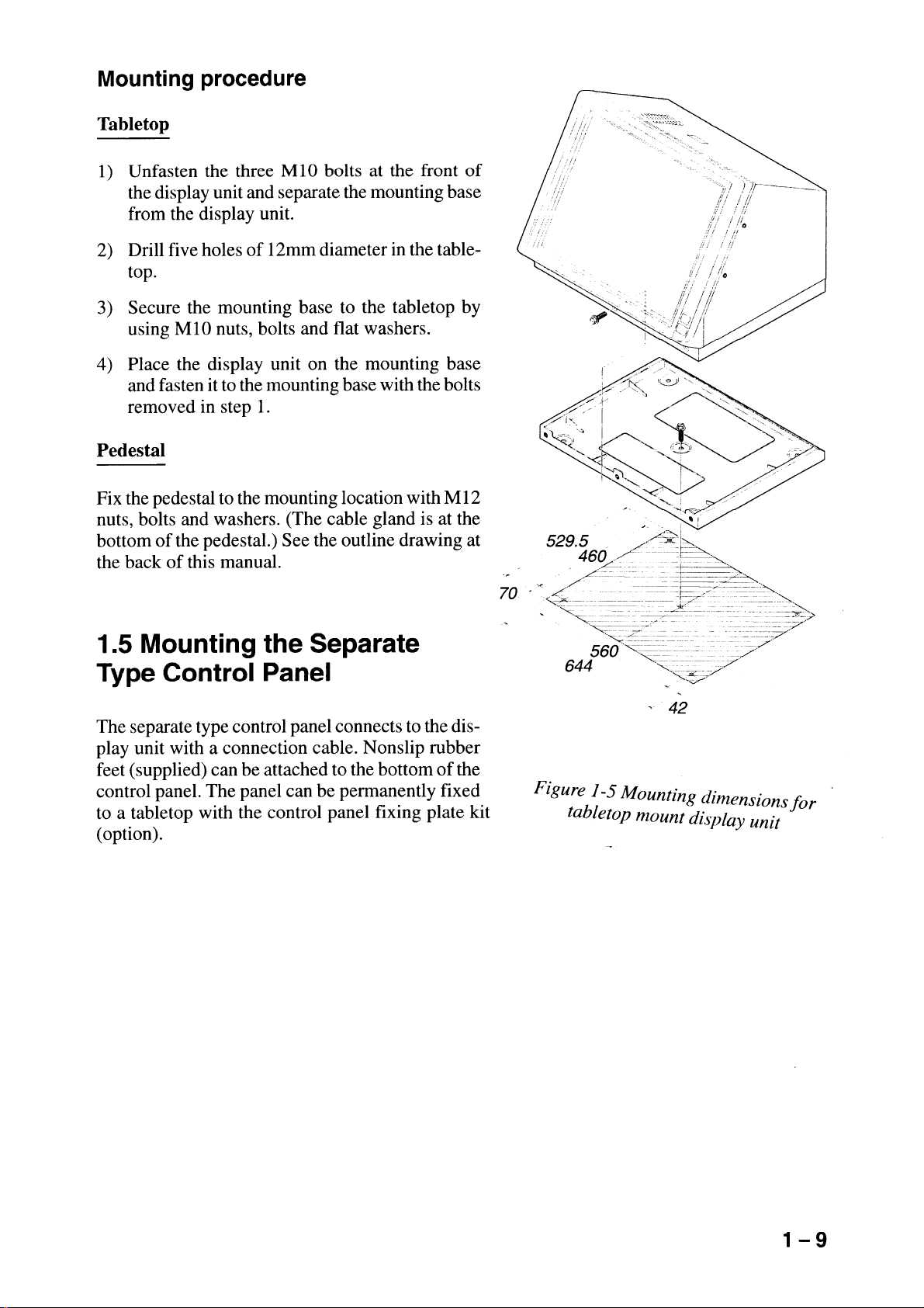
1.4 Mounting the Display Unit
The display unit is designed to be mounted on a tabletop or a pedestal (option).
Before mounting the display unit
If Gyro Converter GC-8 (option) is to be used, install and setup the GYRO PROCESSOR
Board before mounting the display unit, because of the difficulty involved if done after the unit
is mounted, Insstrutions for installtion and setup are in Chapter 4.
Siting considerations
Lpcate the display unit on the bridge in a place where it can be viewed and operated conveniently. In addition, consider the points noted in the figure which follows.
CAUTION
A magnetic compass will be affected if
placed too close to the display unit.
The minimum compass safe distances
for magnetic compasses are
standard compass: 2.7 m
steering compass: 1.8 m
Consider the points mentioned below
when selecting a mounting location for the
display unit.
¥ The orientation of the display unit should
be so the operator views the screen while
facing the bow. This makes determination
of position much easier.
¥ The location should be free of water spray.
¥ The daylight bright type radar display
sunlight. However, locate the unit out of
direct sunlight and away from heat sources
because of heat that can build up inside
the cabinet.
¥ The mounting location should be deter mined consiering the lengt of the signal
cable between the antenna unit and the
display unit. (The signal cable comes in
lengths of 15, 20 or 30 meters; maximum
100 meters.)
¥ Leave sufficient space around the unit for
maintenance and servcing. See the display
unit ouline drawing forrecommended
maintenance space.
1-8
Page 18
Page 19
2. CONNECTIONS
2.1 Antenna Unit Connections
Two cables run between the display unit and the antenna unit, the signalcable and the antenna
cable.
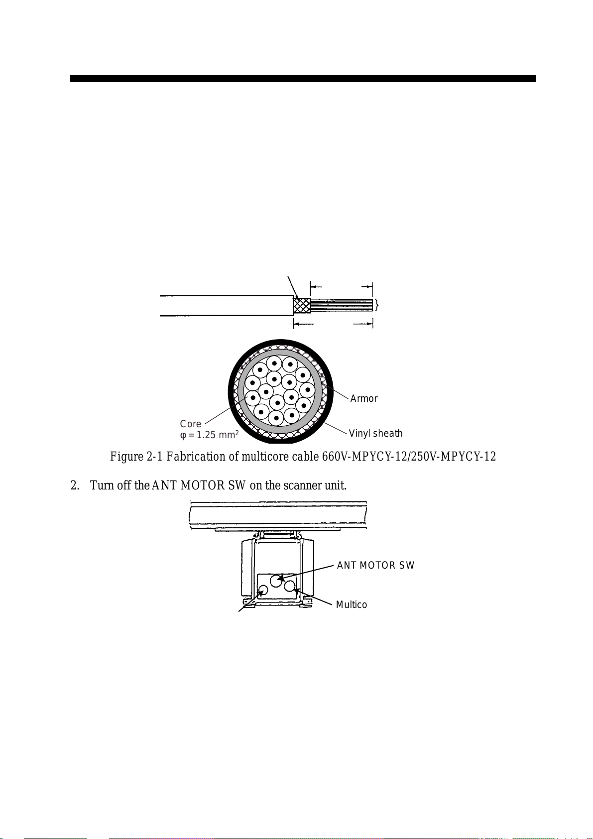
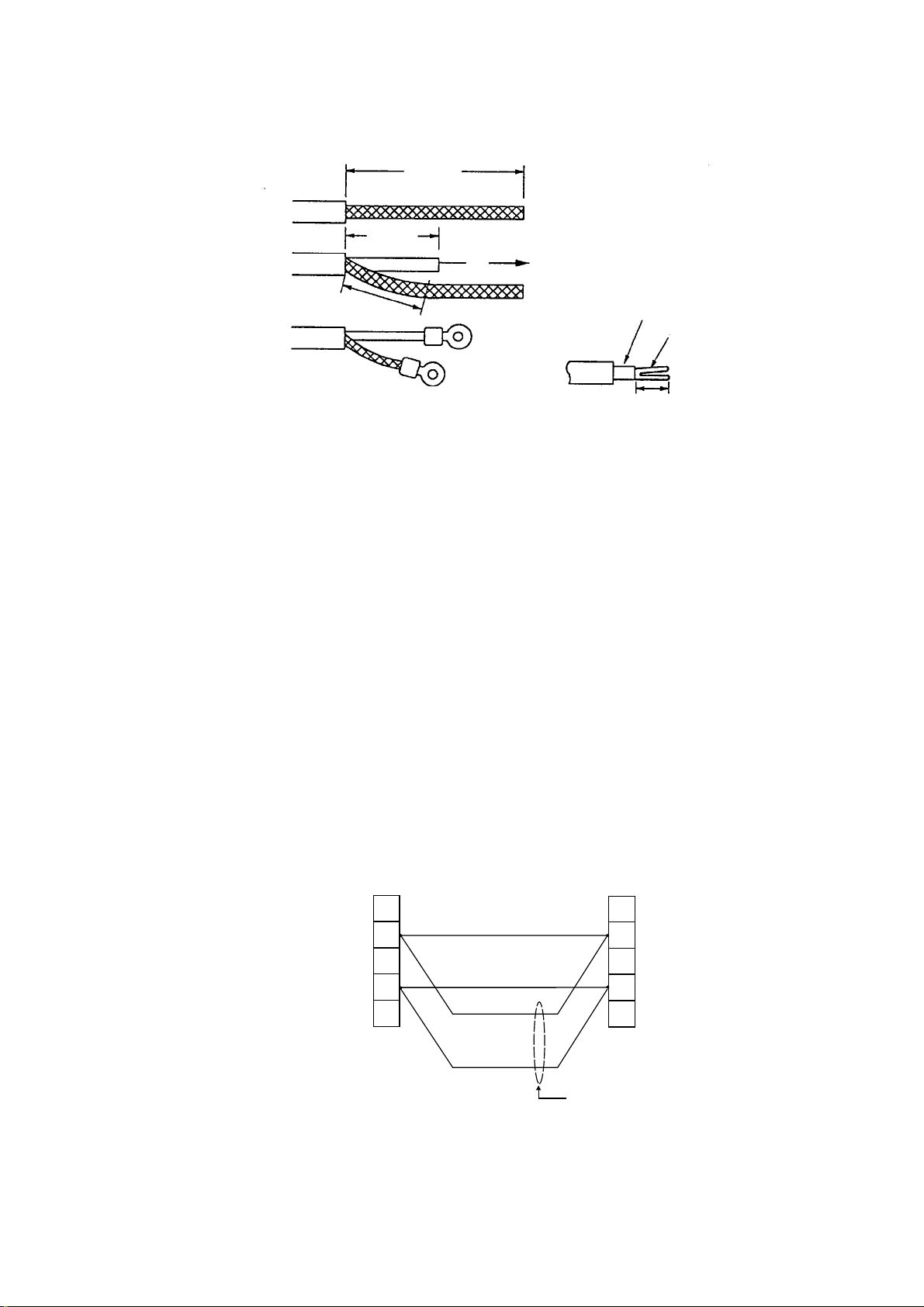
Fabricating antenna cable 660V-MPYCY-12/250V-MPYCY-12 (JIS cable)
1. Shorten the cable making the length from the cable gland to the cable end inside the scanner
unit 450 mm. Remove the vinyl sheath of the cable by 450 mm; the armor by 440 mm.
Armor
440 mm
Conductors
450 mm
Armor
Core
φ = 1.25 mm
2
Vinyl sheath
Figure 2-1 Fabrication of multicore cable 660V-MPYCY-12/250V-MPYCY-12
2. Turn off the ANT MOTOR SW on the scanner unit.
ANT MOTOR SW
Signal cable
(RW-6895)
Multicore cable
(250V-MPYCY-12 or
660V-MPYCY-12)
Figure 2-2 Scanner unit, bow view
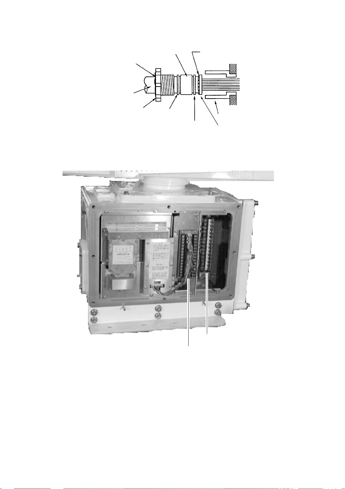
3. Open the left side cover on the scanner unit with the hex wrench (Supplied).
4. Unfasten the cable gland for the multicore cable and remove the gasket and flat washers.
5. As shown in Figure 2-3, slide the clamping gland, flat washers and gasket on the multicore
cable.
2-1
Page 20
6. Fold back armor by 5 mm and pass it through the two flat washers as shown in Figure 2-3.
Gasket
Seal with putty
after tightening.
Vinyl sheath
Clamping gland
Flat
washer
Armor (folded back)
Cable gland
Flat
washer
Flat
washer
Figure 2-3 Passing clamping gland, washers and gasket on the multicore cable
7. Shorten conductors considering their locations on the terminal board STB-1.
STB-1
RTB-801
Figure 2-4 Scanner unit, port side view
8. Confirm that armor is grounded between two flat washers.
9. Remove the sheath of each conductor by 6 mm. Fix crimp-on lugs (FV1.25-4, blue, ø4) to
each conductor. Make sure each connection is secure both electrically and mechanically.
10. Tighten the clamping gland.
11. Seal the cable gland with putty.
12. Connect the conductors to terminal board STB-1 referring to the interconnection diagram
on page S-1.
2-2
Page 21
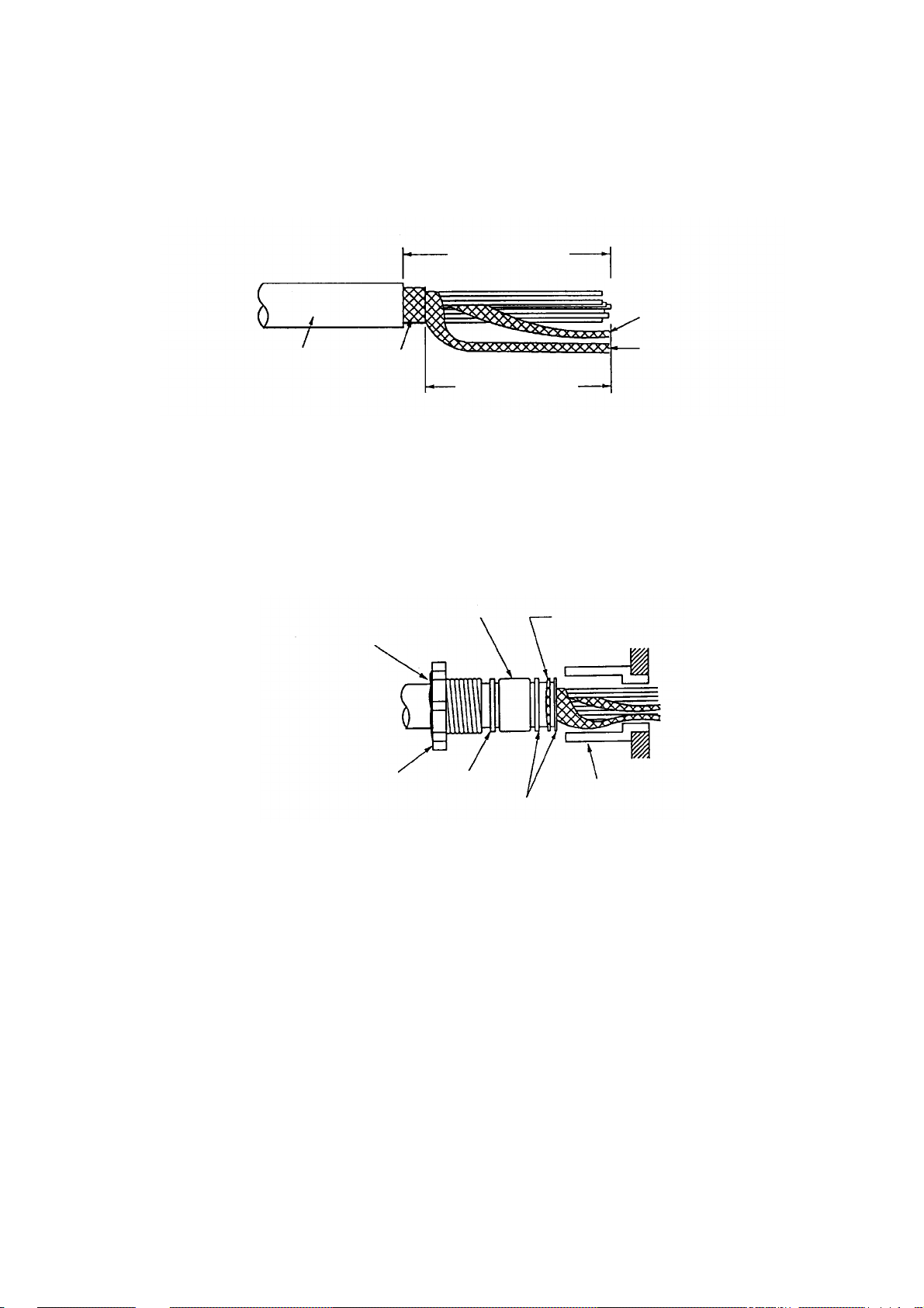
Fabricating signal cable RW-6895
13. At the signal cable gland on the scanner unit, unfasten the clamping gland and remove
gasket and flat washers.
14. Shorten the signal cable making the length from the cable gland to the cable end 500 mm.
Remove the vinyl sheath by 550 mm; the armor by 540 mm.
Approx. 550 mm
Inner shield
Anti-corrosive
vinyl sheath
Armor
Approx. 540 mm
Outer shield
Figure 2-5 Fabricating the signal cable RW-6895
15. Unravel the outer shield with a screwdriver or similar tool to expose the cores beneath the
outer shield. Similarly, expose the cores beneath the inner shield. Mark all cores for future
identification.
16. As shown in Figure 2-6, slide the clamping gland, washers and gasket onto the signal cable.
Fold back the armor by 5 mm, and then pass it through the two flat washers.
Seal with putty
after tightening.
Clamping gland
Gasket
Washer
Armor
Gland body
Washer
Figure 2-6 Passing clamping gland, washers and gasket on signal cable
17. Unfasten the terminal board R TB-801.
18. Pass the signal cable behind the terminal board plate for cable MPYCY-12, and then pass it
through the locking wire saddle.
2 - 3
Page 22
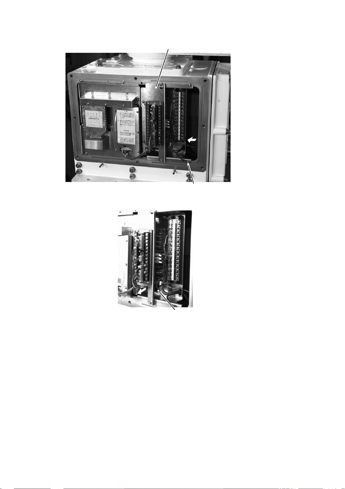
Terminal board fixing plate for RTB-801
Ground terminal
Figure 2-7 Scanner unit, rear view
Locking wire saddle
Figure 2-8 Scanner unit, rear view
19. Fasten the terminal board fixing plate for RTB-801.
2 - 4
Page 23
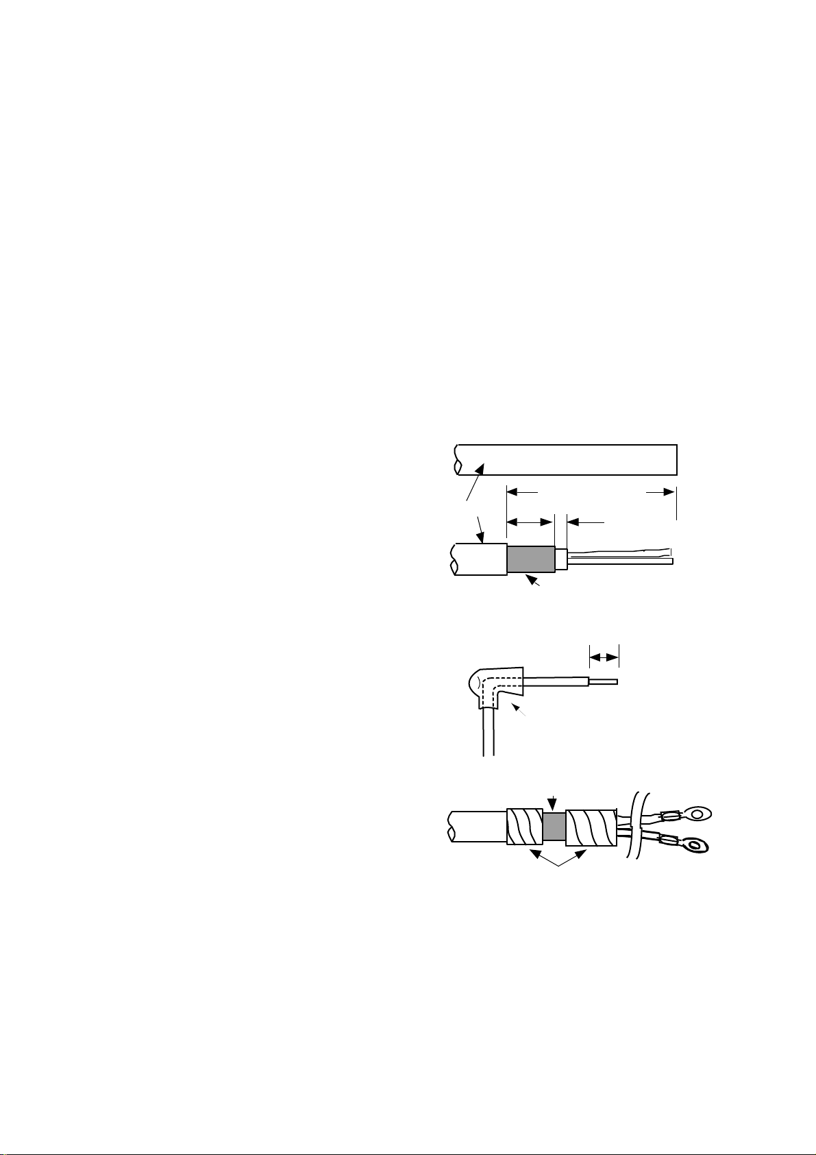
20. Route the signal cable beneath the lower left side of the terminal board fixing plate for the
RTB-801. Shorten conductors of the signal cable considering their locations on the RTB-
801.
50 mm
75 mm
Crimp-on lug
FV1.25-M3
(Red, ∅3)
Fold back the conductor
as illustrated below.
Crimp-on lug
FVD1.25-3
(Red, ∅3)
Inner core
Conductor
6 mm
Coaxial cable
2C-2V
45 mm
Figure 2-9 Fabrication of coaxial cable
21. Shorten the shield considering the distance to the ground terminal on the left side of the
scanner unit chassis. (See Figure 2-7 for location.) Attach the crimp-on-lug FV5.5-4 (ø4,
yellow) to the shield.
22. Remove approx. 6 mm of the vinyl insulation from the end of each conductor and fix the
crimp-on lug FV1.25-M3 (Red) to each conductor. As shown in Figure 2-8, fold back the
coaxial cable four times and attach the crimp-on-lug FVD1.25-3 (ø3, red). Attach the crimpon-lug FVD1.25 (ø3, red) to the shield.
23. Tighten the clamping gland, and then seal the cable gland with putty.
24. Fasten the shield to the ground terminal on the scanner unit chassis.
25. Connect conductors to the terminal board RTB-801 referring to the interconnection diagram.
When the length of the signal cable is more than 150 m, remove the solder at terminal Nos.
24 (red) and 26 (black) on the DJ-1 connector . (#24 and #25 are spares.). Fasten the wires as
shown below.
TB801
14
16
SCANNER
UNIT
Length 150 m
or more
HEATER HOT
+12V
DJ-1
14
16
DISPLAY
UNIT
YELLOW, LARGE
WHITE, LARGE
RED, LARGE
BLACK, LARGE
Figure 2-10 Wiring on terminal boards when length of signal cable is 150 m or more
26. Check for miswiring, loose screws. Grease the fixing bolts for the cover, gasket, and tap
holes in the scanner chassis. Attach the cover.
2-5
Page 24
When the De-Icer is installed
1) Before beginning any work on the scanner unit, turn off both the DE-ICER switch (S31) on
the sub panel of the display unit and the breaker for the de-icer line at the main switchboard
to remove the power (100 VAC, 1ø) to the de-icer. (T urning off the power to the display unit
has no effect.)
2) The neck of the scanner unit becomes VERY HOT when the de-icer is working. (The deicer turns on when ambient temperature is below 0°C.)
2.2 Display Unit Connection
Two cables are terminated at the display unit: the signal cable RW-4839 or RW-6895 and the
power cable. The signal cable, available in lengths of 15m, 20m, or 30m, comes with a connector preattached to it for connection to the display unit.
Fabricating power cable DPYCY -3.5
1) Remove the vinyl jacket by 150mm.
2) Cut off jute tape wrapped around the braided
shield.
3) Unravel the braided shield to expose the cores
by about 120mm.
4) Slip the terminal cap onto the core.
5) Remove insulation of cores by about 10mm.
Fix crimp-on lugs to the cores and braided
shield.
6) Cover the braided shield with vinyl tape, leaving the portion which will lie inside the cable
clamp untaped.
(a)
Vinyl jacket
(b)
(c)
(d)
DPYCY-3.5
Approx. 150 mm
15 mm
5 mm
Armor
10 mm
Terminal cap
Clamp here
2-6
Taping
Figure 2-11 How to fabricate
power cable DPYCY-3.5
Page 25

Leading in cables to the display unit
To lead in cables easily, unfasten the cable clamp at the right side of the display unit.
Cable
clamp
Figure 2-12 Location of cable clamp inside the display unit
Tabletop
Cables can be led in through the cable gland at the rear or underside of the unit.
Pedestal
Lead in cables through the cable gland
at the bottom right-hand side of the ped-
Process cable same as
on tabletop type
estal. Pass cables through the cable
clamp and tighten the cable clamp. Fix
cables to the pedestal frame with cable
ties as shown in Figure 2-13. Finally,
pass cables through the cable clamp at
the right side of the display unit and then
tighten the cable clamp.
Leaving sheath
intact, pass cable
through cable
clamp
Figure 2-13 How to lead in cables
through the pedestal
2 - 7
Page 26

Connections
Power cable
Connect the power cable to the filter at the right
hand side of the display unit. Cover the filter terminals with the terminal caps (supplied) to insulate the terminals.
Filter
Power
cable
Figure 2-14 Location of filter
inside the display unit
Gyro signal
Solder the 5 pin and 3 pin VH connectors (supplied) to the gyrocompass cable. Plug in the
connectors on the GYRO CONVERTER Board. For further details, see page 4-2.
GYRO CONVERTER
Board
Rear panel
Figure 2-15 Location of GYRO CONVERTER Board
HOW TO ATTACH NH CONNECTOR TO SIGNAL CABLE
NH connector wire
Shrink tubing
2 - 8
NH connector
housing
1 Insert NH connector
wire into NH connector
housing.
20mm
2 Cut shrink tubing
in 20 mm lengths and
slip onto each wire.
Solder
3 Solder connector
to signal cable.
4 Heat shrink
tubing with soldering iron.
Page 27

Grounding
The display unit must be grounded from
a grounding stud having a wing nut located at the point shown in Figure 2-16.
Tabletop type Pedestal type
CAUTION
An ungrounded unit can cause electrical shock when
its metallic parts are touched and give off or receive
electromagnetic interference.
Figure 2-16 Grounding the display unit
Radar buoy
Solder the radar buoy signal line to the "BUOY" connector on the VDA Board. Connect the
trigger line to the corresponding connector on the INT Board.
Signal input/output circuit (INT Board INT-9170)
Nav data
+5V
J450
1 TXD1-H
2 TXD1-C
3 RXD1-H
4 RXD1-C
+5V
5 DTR1-H
6 DTR1-C
7 DSR1-H
8 DSR1-C
2SC1015
PC900V
+5V
1
2
+5V
+5V+5V
6
Vcc
A
X
GND
OUT
5
4
Figure 2-17 INT Board circuit
For other input/output circuits, see the circuit diagram of the INT Board at the back of this
manual.
2-9
Page 28

Table 2-1 Input and output signals on the INT Board
emanlangiSnoemaN
bcp
langiStupnI
langisoryG*4J
goldeepS
langis
)edit(langis
)deeps(langis
youbradaR
langis
yalpsidetomeR
langis
elgnaredduR
langis
langiStuptuO
APRAlanretxE
langis
GOL844Jnip3,HN.cte,mn/seslup002
rotacidnitnerruC
VAN
rotacidnitnerruC
VAN
YOUB
TOR
rotcennoC
.on
*5J
954Jnip4,HNdesutoN
ESRUOC
064Jnip3,HNdesutoN
DEEPS
RADAR
RADAR-TXE
7-JRro
REDDUR
APRA-TXE444Jnip8,HN5082-AF,gniraeb,gnidaeh
544Jnip4,HN
854Jnip8,HN
464Jnip7,HN
epyt
rotcennoC
nip5,HV
nip3,HV
elbacilppA
tnempiuqe
skrameR
bcpnO:*
)noitpo(6011P46A
reggirtxT
yalpsidevalS
langis
langisrezzuBZUB-TXE154Jnip3,HN3-12-30POlangisevirdrezzub
langisrezzuB
)CA(
langisrotinoM944Jnip01,HN,suonorhcnysREV
8-JR8-JR654Jnip4,HN
atadSNIATAD.SNI554Jnip5,HN
7-JR7-JR754Jnip51,HN
EVALS244J
)CA(
langiStuptuO/tupnI
344J
ZUB-TXE
254Jnip2,HNpma/wrekaepSlangisrekaeps
nip8,HN,141-DC,041-DC
nip8,HN
,gniraeb,gnidaeh
,005-DG
,008-DMF
1*0008-DMF
roftinuyalpsiD:1*
seires0082-RF
desuebnacradar
yalpsidevalssa
.tinu
)tam
reggirtxT,oediv
,suonorhcnysROH
-rofCSTN(oediv
2 - 10
atadvaNATADVAN054Jnip8,HN
atadAPRAATADAPRA454Jnip5,HN
Page 29

J458
J464
J441
J445
J452
J463
J467
J443
DTB-2#1
J442
J461
J460
#8
J444
J448
J457
J450
J454
J455
J451
Figure 2-18 Location of connectors on the INT Board
J449
J459
J456
2 - 11
Page 30

Grounding cables and covering unused cable slots in the cable clamp
Cover unused cable
slots with aluminum tape.
Ground shield
of cables by
Fasten ground wire
of cables by fixing
screws for cable clamp.
cable clamp.
Figure 2-19 Cable clamp
CAUTION
1) The display unit must be grounded. Failure to
ground the unit may cause electrical shock when its
metallic parts are touched and give off or receive
electromagnetic interference.
2) Cover unused cable slots in the cable clamp with
aluminum tape to prevent foreign objects from
falling into the display unit through the cable slots.
2-12
Page 31

2.3 Changing Power Specifications
This radar can be powered by 100V AC or 220V AC, and is set at the factory for connection to
a 100V power supply. To power the unit by 220V AC, remove jumper JP13 on the POWER
Board as shown in the procedure below.
CAUTION
Turn off the power before executing the procedure
shown below.
Procedure
1) Turn off the power.
2) Unfasten the four screws circled in the
illustration at right.
3) Remove the power assembly.
4) Remove the power assembly cover.
5) For 220V power supply, remove jumper
wire JP13 on the POWER Board.
6) Mount the power assembly.
rewoPeriwrepmuJ
31PJ
JP13
RT-9183
C42
CAV001trohS
CAV022evomeR
C8
C6
2-13
Page 32

2.4 Power Supply Unit
Wire the unit as shown in the interconnection diagram.
TB
PTB14
TB
PTB11
Thermal relay
K2
Relay K3
Relay K1
Photo No. 3148
TB
PTB13
TB
PTB12
Figure 2-20 Power supply unit PSU-004
The type and rating of the thermal relay (K2) are as below.
sniaMs'pihStinUrennacS
epyTgnitaR
3,CAV022/002 ∅ 6200-BSRA7.13/HN0-RTA3.2
3,CAV044/083 ∅ 1300-BSRA8.03/HN0-RTA0.1
3,CAV022 ∅ zH05,8800-BSRA7.13/HN0-RT*)XAM(A6.2
3,CAV022 ∅ zH06,9800-BSRA7.13/HN0-RT*)XAM(A6.2
3,CAV044 ∅ zH06,0900-BSRA8.03/HN0-RT*)XAM(A2.1
)2K(yaleRlamrehT
*: Set the rating to maximum ( 2.3A to 2.6A or 1.0A to 1.2A) for HSC radar.
2-14
Page 33

3. INITIALIZATION AND ADJUSTMENT
3.1 Menus for Initialization and Adjustment
Accessing the menus
The menus for initialization and adjustment of this radar are locked to prevent adjustment by
the user. To access them;
1) Turn off the power.
2) Turn on the #4 segment of DIP Switch S1 on the SPU Board.
4
S1
1
Figure 3-1 Display unit (top view, cover removed)
and SPU Board
Menu operation
1) Press the [RADAR MENU] key.
2) Press appropriate numeric key to select menu desired.
3) Press numeric key to select item.
4) Press same numeric key pressed in step 3 to select option.
5) Press [ENTER] to register selection.
Menu description and menu tree
See pages 3-6 and 3-11, respectively.
Restoring default settings
1) Press [RADAR MENU] [0] [0] [2] [0] [0] [0] [0] to select FACT ORY DEFAULT on the
INITIAL SETTING 4 menu.
2) Press the [ENTER] key.
3) Wait for 10 seconds.
4) Turn power off, and on again.
5) Press [RADAR MENU] [0] [0] [2] [0] [0] [0] [2] to select MODEL on the INITIAL
SETTING 4 menu.
3–1
Page 34

6) Press the [2] key several times to select OTHER S-BAND.
7) Press the [ENTER] key.
3.2 Heading Alignment
Antenna unit mounted error (heading reed switch timing error) can be compensated at the display unit.
Correct bearing
relative to heading
Target
α
Antenna mounted error
to port (heading switch
advance)
000
010
350
020
340
330
320
310
300
290
280
270
260
250
240
230
220
210
200
030
150
160
190
170
180
Picture appears
deviated clockwise.
Figure 3-2 Heading alignment error
040
140
050
060
120
130
α
070
080
090
100
Apparent
110
position
of target
Apparent position
Target
β
Antenna mounted error
to starboard (heading
switch delayed)
of target
000
010
350
340
330
320
310
300
290
280
270
260
250
240
230
220
210
200
190
170
180
Picture appears
deviated counterclockwise.
β
020
030
040
050
060
070
080
090
Correct
100
110
bearing
120
relative to
130
140
heading
150
160
Procedure
1) Turn on the power. Press [RADAR MENU] [0] [0] [2] [2] to select HD ALIGN on the
INITIAL SETTING 1 menu.
2) Select a target echo (by gyrocompass, for example) at a range between 0.125 and 0.25nm,
preferably near the heading mark.
3) Operate the EBL control to bisect the target echo. (The value shown on the display is antenna position in relation to ship's bow.)
4) Press [ENTER] to finish.
3.3 Adjusting Sweep T iming
Sweep timing differs with respect to the length of the signal cable between the antenna unit and
the display unit. Adjust sweep timing at installation to prevent the following symptoms:
• The echo of a "straight" target (for example, pier), on the 0.25nm range, will appear on the
display as being pulled inward or pushed outward. See Figure 3-3.
• The range of target echoes will also be incorrectly shown.
Correct Target pushed Target pushed
inward outward
Figure 3-3 Examples of correct and
3-2
incorrect sweep timings
Page 35

Procedure
1) Turn on the power . Press [RADAR MENU] [0] [0] [2] [3] to select TIMING ADJ on the
INITIAL SETTING 1 menu.
2) Transmit on the 0.25nm range.
3) Adjust radar picture controls to display picture properly.
4) Select a target echo which should be displayed straightly.
5) Adjust the VRM control to straighten the target echo.
6) Press the [ENTER] key.
3.4 Adjusting Video Signal Level
When the signal cable is very long, the video amplifier input level decreases, shrinking target
echoes. To prevent this, confirm (and adjust if necessary) video amplifier input level.
Procedure
1) Connect an oscilloscope to TP3 on the INT Board (INT-9170).
2) Transmit on the 12nm range. Take trigger at TP10 on the same board.
3) Adjust VR1 on the INT Board so the value of TP3 is 4Vpp. (For secondary display, adjust
VR2 for same level.)
VR2
VR1
INT Board
TP3
Figure 3-4 Location of INT Board
3–3
Page 36

3.5 Suppressing Main Bang
If main bang appears at the screen center, suppress it as follows.
Procedure
1) Turn on the power. Transmit on a long range and then wait ten minutes.
2) Adjust [GAIN] control to show a slight amount of noise on the display.
3) Select the 0.25nm range. Adjust the [A/C SEA] control to suppress sea clutter.
4) Open the tuning compartment on the control unit.
5) Set VR901(MBS-L) at two o'clock and then slowly turn VR902 (MBS-T) clockwise to
suppress main bang.
6) If main bang still exists, turn VR901 clockwise slightly, and then slowly turn VR902 clockwise. Note that excessive main bang erases targets in close range.
TUNE
switch
Up: AUTO
Down: MAN
AUTO
AUTO
MAN
ON
OFF
ANTENNA
DEGAUSS
PM-ON/OFF
Tuning compartment
TUNE
GYRO SET
MBS-L
MBS-T
HOLD
ERROR
STBY
TUNE
control
VR901
(MBS-L)
VR902
(MBS-T)
Figure 3-5 Control unit, location of tuning compartment
3.6 Confirming Tuning
The radar receiver can be tuned both automatically and manually . Confirm that the radar can be
tuned both automatically and manually.
Procedure
1) Turn on the power. Set the TUNE switch in the top right hand panel to MANU.
2) Transmit on the 48nm range.
3) Adjust sensitivity and picture brilliance. Turn the [A/C SEA] and [A/C RAIN] controls
fully counterclockwise (off).
4) While observing the picture, turn the [TUNE] control in the tuning compartment slowly
counterclockwise (clockwise) more than twice to get best (worst) tuning point.
3 - 4
Page 37

5) Turn the [TUNE] control slowly clockwise (counterclockwise) to display the longest tuning bar.
6) Set the TUNE switch to AUTO and wait about 10 seconds (about four rotations of the
antenna).
7) Confirm that the radar found best tuning point. Peak tuning is obtained when about 80% of
the tuning indicator lights.
3.7 Confirming Magnetron Heater Voltage
Magnetron heater voltage is adjusted at the factory. Confirm that magnetron heater voltage is
within the prescribed rating as follows:
1) Turn on the radar and select the 0.125 mile range.
2) Press [RADAR MENU] [0] [0] [2] [0] to open the INITIAL SETTING2 menu.
3) Press [5] to select the 5. SCANNER STOPPED field and the TX option.
4) Turn off the antenna switch in the display unit.
5) Connect a multimeter, set to the 10 VDC range, between #12(+) of P801 and the chassis.
6) The multimeter should read 9.2-9.4 V. If not, adjust VR1.
7) “Transmit” on the 48 mile range.
8) The multimeter should read 7.3-8.3V.
9) Press [RADAR MENU] [0] [0] [2] [0] [5] to select the 5. SCANNER STOPPED field and
the ROTATE option.
10) Turn on the ANT MOT OR SW on the scanner unit.
PCB 03P9243
ANT MOTOR SW
Signal cable
Multicore cable
Figure 3-6(a) Scanner unit, bow view
VR1
P801
Figure 3-6(b) Scanner unit, stern side view
3-5
Page 38

Page 39

Page 40

Page 41

Page 42

Page 43

Page 44

Page 45

Page 46

Page 47

Page 48

Page 49

Page 50

Setting method 2: by make and model of gyrocompass
Table 4-2 Setting GYRO CONVERTER Board by make and model of gyrocompass
rekaMsledoMnoitacificepSWS
ONURUF007-YGpetsCD
ztuhcsnA3,2dradnatSsuonorhcnysCA
6,4dradnatSsuonorhcnysCA
02dradnatSpetsCD
awagokoY
cetvaN
htialP(
)epyt
htialPIII/IITAGVANsuonorhcnysCA
cemikoT
yrrepS(
)epyt
ikasawaK18-XGsuonorhcnysCA
nworbamrA1-LKM,01-KM
nostreboR08-RKSpetsCD
3/2/A1/1-C
55-B,55-A
005/X003
003
3/2-SPI
05-ZMC
etoN
11/2/1-SE
002-GT
H/L732RP
12MG
41-KM
T/2/1-DOM
302/
0006-GTpetsCD
11-MGsuonorhcnysCA
4-DOM
/X052-ZMC
/002/001-ZMC
3/1/Z1-D,rJ1-C
/201/101-TLG
701/K601/301
011/A11-SE
0002/R222RP
IE-KN,NE-KN
041/031-RSpetsCD
0005/001-GT
/031/753-RP
71-SE,041
202/102-TLG
61-SE,021-RS
03/02/01-KM
,1531SEIRES
x081V001
rotcellocnepo,eriw-5
zH06/05
x063
zH06/05
x063
x081V53
zH06/05
x063
petsCD
x081V53
zH06/05
x063
pets
x081V53
zH06/05
x063
zH06/05
x63
zH06/05
x09
petsCD
x081V07
x081V07
petsCD
x081V07
x081V42
zH06/05
x09
petsCD
x081V53
zH06/05
x09
petsCD
x081V05
x081V53
V06/05:egatlovrotoR
V22:egatlovrotatS
V06/05:egatlovrotoR
V09:egatlovrotatS
)+(eriw-3,)-(MOC
suonorhcnysCA
V06/05:egatlovrotoR
V22:egatlovrotatS
x063suonorhcnysCDFFOFFOFFOFFOFFOFFONONO-NOFFO-omeR
)-(eriw-3,)+(MOC
suonorhcnysCA
V001:egatlovrotoR
V09:egatlovrotatS
)-(eriw-3,)+(MOC
V06/05:egatlovrotoR
V86:egatlovrotatS
suonorhcnysCA
V011/001:egatlovrotoR
V09:egatlovrotatS
suonorhcnysCA
V011/001:egatlovrotoR
V22:egatlovrotatS
)+(eriw-3,)-(MOC
rotcellocnepo,eriw-5
)-(eriw-3,)+(MOC
V001:egatlovrotoR
V09:egatlovrotatS
V011/001:egatlovrotoR
V09:egatlovrotatS
)-(eriw-3,)+(MOC
)+(eriw-3,)-(MOC
WS
WS
WS
WS
WS
WS
WS
WS
WS
1-1
2-1
3-1
4-1
5-1
6-1
7-1
8-1
1-2
NOFFOFFONOFFOFFONONO- FFOFFO,4#
FFOFFOFFOFFOFFOFFOFFOFFOFFONOFFO,1#
FFOFFOFFOFFOFFOFFOFFOFFOFFOFFOFFO,1#
NOFFOFFONOFFOFFONONO-NOFFO,4#
FFOFFOFFOFFOFFOFFOFFOFFOFFONOFFO,1#
NOFFOFFONOFFOFFONONO-NOFFO,4#
FFOFFOFFOFFOFFOFFOFFOFFOFFOFFOFFO,1#
NOFFOFFONOFFOFFONONO– NOFFO-omeR
FFOFFOFFOFFOFFOFFOFFOFFOFFOFFOFFO,1#
NONOFFOFFOFFOFFOFFOFFOFFOFFOFFO,1#
FFONOFFOFFOFFOFFOFFOFFOFFOFFOFFO,1#
NOFFOFFONOFFOFFONONO– FFOFFO,4#
NOFFOFFOFFONOFFOFFOFFO– FFOFFO,4#
NOFFOFFONOFFOFFONONO– FFOFFO,4#
NOFFOFFONOFFOFFONONO-NOFFO,4#
FFONOFFOFFOFFOFFOFFOFFOFFOFFOFFO,1#
NOFFOFFONOFFOFFONONO– NOFFO,4#
FFONOFFOFFOFFOFFOFFOFFOFFOFFOFFO,1#
NOFFOFFONOFFOFFONONO– FFOFFO,4#
NOFFOFFONOFFOFFONONO– NOFFO,4#
WS
2-2
3-2
1PJ2PJ3PJ4PJ5PJ
2#-1#1#
6#,5#
2#2#1#1#
3#,2#
2#1#1#1#
3#,2#
2#-2#2#
6#,5#
2#2#1#1#
3#,2#
2#-
ev
2#-2#2#
6#,5#
1#1#1#1#
3#,2#
2#–
ev
2#2#1#1#
3#,2#
1#1#1#1#
3#,2#
1#1#1#1#
3#,2#
2#– 1#1#
6#,5#
2#– 1#1#
6#,5#
2#– 1#1#
6#,5#
2#– 2#2#
6#,5#
1#1#1#1#
3#,2#
2#– 2#2#
6#,5#
1#1#1#1#
3#,2#
2#– 1#1#
6#,5#
2#– 2#2#
6#,5#
∗∗
∗∗
4-6
Page 51

Page 52

Page 53

Page 54

Page 55

Page 56

Page 57

Page 58

Page 59

Page 60

Page 61

Page 62

Page 63

Page 64

Page 65

Page 66

Page 67

Page 68

Page 69

Page 70

Page 71

Page 72

Page 73

Page 74

Page 75

Page 76

Page 77

 Loading...