


Pulse HW Fully Condensing Hydronic Boiler
INSTALLATION AND
OPERATION MANUAL
Gas Pulse Combustion
Hydronic Heating Boiler (PHW)
Serial/National
Board #
Model
Fulton Order
Sold To
Job Name
Date
PHW-IOM-2013-0214


Questions? Call (315) 298-5121, or visit us online at www.fulton.com
PHW-IOM-2013-0214 TABLE OF CONTENTS
0-1
Introduction 1-1
Overview .............................................................................................................. 1-2
Warnings & Cautions ............................................................................................1-2
Disclaimers and Local Codes ................................................................................1-2
Installation 2-1
Product Overview ................................................................................................. 2-2
Review Shipment Contents .................................................................................. 2-2
Placement & Rigging ........................................................................................... 2-3
Clearances and Serviceability ..............................................................................2-5
Install Isolation Mounts ....................................................................................... 2-5
HOW TO INSTALL ELASTOMER CUBE ISOLATION MOUNTS ........................................................25
HOW TO INSTALL SPRING ISOLATION MOUNTS .........................................................................26
HOW TO INSTALL SEISMIC SPRING ISOLATION MOUNTS...........................................................27
Install Boiler Trim .................................................................................................2-8
Water Chemistry Requirements ...........................................................................2-8
Install Water Piping .............................................................................................. 2-9
Install Condensate Drain .................................................................................... 2-11
INSTALL CONDENSATE DRAIN PIPING .....................................................................................212
Install pH Neutralization Kit ...............................................................................2-12
Install Gas Piping ................................................................................................2-14
Install Field Wiring .............................................................................................2-14
Air Intake Supply Piping Installation Preparation .............................................. 2-15
CEMENTING JOINTS ...................................................................................................................216
Install Intake Mu er ......................................................................................... 2-17
Preparing to Install Exhaust Vent Piping ............................................................2-17
Exhaust Mu er Installation ..............................................................................2-18
Air Intake & Exhaust Piping Requirements for the Pulse Boiler ........................2-19
Air Intake Supply and Exhaust Vent Installation ...............................................2-20
Vertical Vent Flashing and Installation .............................................................. 2-21
Vertical Vent Termination ..................................................................................2-21
Horizontal Installation Wall Penetrations ......................................................... 2-24
Wall Thimble Installation .................................................................................. 2-24
Horizontal Vent Termination ............................................................................. 2-25
After Installation/Prior to Start-Up .................................................................... 2-26
Installation Checkpoints ...................................................................................2-28
Testing Ignition Safety Shut O ........................................................................2-28
Measure Gas Flow Rate ..................................................................................... 2-28
TO CORRECT INPUT ADJUST GAS PRESSURE REGULATOR ....................................................229
Rating the Boiler ................................................................................................2-29
To Check for High Gas Pressure ..........................................................................2-29
For High Gas Pressure Installations Using Fisher Regulators .............................2-29
Before Leaving the Installation ......................................................................... 2-30
Operation 3-1
Before Start Up .....................................................................................................3-2
Start Up ................................................................................................................3-2
LINKAGE ADJUSTMENT FOR PULSE MODULATED BOILERS.......................................................33
IF THE BOILER DOESN’T START ..................................................................................................35
Sequence of Operation for Modulated Pulse Hydronic Boilers ............................ 3-6
General Operation of the Boiler ........................................................................... 3-6
Programming Instructions for the SOLA Control ................................................. 3-6
CHANGING/TESTING SOLA HIGH LIMIT SETPOINT ..................................................................310
VERIFYING CHANGES TO HIGH LIMIT SETPOINT .....................................................................310
ACCESSING LOCKOUT HISTORY AND CLEARING LOCKOUTS .....................................................311
PROCEDURE FOR REMOTE FIRING RATE USING A 420MA SIGNAL SINGLE BOILER ...........312
PROCEDURE FOR REMOTE SETPOINT USING A 420MA SIGNAL SINGLE BOILER ................313
PROCEDURE FOR LEAD/LAG WITH OUTDOOR RESET WITH MULTIPLE BOILERS ....................314
SINGLE BOILER OUTDOOR RESET PROGRAMMING ..................................................................318
Third Party SOLA Control ....................................................................................3-21
LEAD/LAG OUTDOOR RESET CONFIGURATION USING COMMUNICATION PORT 2 ..................321
STAND ALONE BOILERS CONTROLLED BY A THIRD PARTY CONTROL ......................................321
GATEWAYS .................................................................................................................................321
Maintenance 4-1
General ................................................................................................................. 4-2
Daily Maintenance and Inspection Schedule ......................................................4-2
Monthly Maintenance and Inspection Schedule .................................................4-2
Annual Maintenance and Inspection Schedule ................................................... 4-3
After All Repairs and Maintenance ...................................................................... 4-4
Troubleshooting ...................................................................................................4-5
Reviewing Diagnostics on SOLA Control ..............................................................4-6
TAKING SCREEN SHOTS................................................................................................................47
Warranty & Parts 5-1
Standard Warranty for Fulton Pulse Boilers
with Carbon Steel Exhaust Pipes .......................................................................... 5-2
Standard Warranty for Fulton Pulse Boilers
with Duplex Stainless Steel Exhaust Pipes ...........................................................5-3
Parts ..................................................................................................................... 5-4

© The Fulton Companies 2013
TABLE OF CONTENTS PHW-IOM-2013-0214
0-2

Questions? Call (315) 298-5121, or visit us online at www.fulton.com
1-1
INTRODUCTION
INTRODUCTION
1
INSTALLATION
2
OPERATION
3
MAINTENANCE
4
WARRANTY & PARTS
5

© The Fulton Companies 2013
1-2
INTRODUCTION PHW-IOM-2013-0214 SECTION 1
Overview
Prior to shipment, the following inspections and tests are
made to ensure the highest standards of manufacturing for
our customers:
§ Material inspections
§ Manufacturing process inspections
§ American Society of Mechanical Engineers (ASME)
welding inspection
§ ASME hydrostatic test inspection
§ Electrical components inspection
§ Operating test
§ Final engineering inspection
§ Crating inspection
This manual is provided as a guide to the correct operation
and maintenance of your Fulton equipment, and should be
read in its entirety and be made permanently available to the
sta responsible for the operation of the boiler. It should not,
however, be considered as a complete code of practice, nor
should it replace existing codes or standards which may be
applicable. Fulton reserves the right to change any part of
this installation, operation and maintenance manual.
Installation, start-up, and maintenance of this equipment
can be hazardous and requires trained, quali ed installers
and service personnel. Trained personnel are responsible
for the installation, operation, and maintenance of this
product, and for the safety assurance of installation,
operation, and maintenance processes. Do not install,
operate, service or repair any component of this
equipment unless you are quali ed and fully understand
all requirements and procedures. Trained personnel
refers to those who have completed Fulton Service School
training speci c to this product.
When working on this equipment, observe all warnings,
cautions, and notes in literature, on stickers and labels, and
any additional safety precautions that apply. Follow all safety
codes and wear appropriate safety protection. Follow all
jurisdictional codes and consult any jurisdictional authorities
prior to installation.
Warnings & Cautions
WARNINGS and CAUTIONS appear in various chapters of this
manual. It is critical that all personnel read and adhere to all
information contained in WARNINGS and CAUTIONS.
§ WARNINGS must be observed to prevent serious injury
or death to personnel.
§ CAUTIONS must be observed to prevent damage
or destruction of equipment or loss of operating
e ectiveness.
All Warnings and Cautions are for reference and guidance
purposes, and do not substitute for required professional
training, conduct, and strict adherence to applicable
jurisdictional/professional codes or regulations.
Disclaimers and Local Codes
Installation of the equipment shall conform to all the
requirements or all national, state and local codes established
by the authorities having jurisdiction or, in the absence
of such requirements, in the US to the National Fuel Gas
Code ANSI Z2231/NFPA 54 latest edition, and the speci c
instructions in this manual. Authorities having jurisdiction
should be consulted prior to installation.
When required by local codes, the installation must conform
to the American Society of Mechanical Engineers Safety Code
for Controls and Safety Devices for Automatically Fired Boilers
(ASME CSD-1).
The boiler heat exchanger is manufactured and stamped
in accordance with ASME Boiler and Pressure Vessel Code,
Section IV for a maximum allowable working pressure of 160
psig. Maximum allowable working temperature varies by
design (210 F for duplex; 240 F for carbon).

Questions? Call (315) 298-5121, or visit us online at www.fulton.com
2-1
INSTALLATION
INTRODUCTION
1
INSTALLATION
2
OPERATION
3
MAINTENANCE
4
WARRANTY & PARTS
5
© The Fulton Companies 2013
INSTALLATION PHW-IOM-2013-0214 SECTION 2
2-2
! WARNING
All information in this manual is for
reference and guidance purposes,
and does not substitute for required
professional training, conduct,
and strict adherence to applicable
jurisdictional/professional codes and
regulations.
4 CAUTION
This boiler is certi ed for indoor
installation only.
This boiler is not designed for use in
systems where water is continuously
replenished. Mineral build-up may
occur on the heat transfer surfaces
and result in overheating and
possible heat exchange failure. The
warranty is valid for closed loop
systems only.
Fulton cannot be held responsible
for the selection, engineering,
installation, or sizing of any
additional equipment or components
of the hydronic heating system.
This boiler, when installed in
conjunction with a refrigeration
system, must be installed so that the
chilled medium is piped in parallel
with the boiler with appropriate valves
to prevent the chilled medium from
entering the boiler. If the boilers are
connected to heating coils located in
air handling units where they may be
exposed to refrigerated air circulation,
such boiler piping systems must be
equipped with ow control valves or
other automatic means to prevent
gravity circulation of the boiler water
during the cooling cycle.
Product Overview
Prior to the performance of installation, operation, or maintenance procedures,
personnel should become familiar with the equipment (Table 1, Figures 1 and 2)
and its components.
The Fulton Pulse combustion hydronic boiler is an automatic gas red, direct
vent boiler. This boiler utilizes pulse
combustion principle. It does not
have conventional burner controls
or chimney. The combustion
components are of integral design
with the heat exchanger. Each boiler
is built to ASME and CSD-1 Codes,
hydrostatically tested, test red, and
shipped as a complete packaged
unit.
All installations must be in
accordance with the American
National Standard “National Fuel
Gas Code,” latest edition, and with
the requirements of local utilities or
other authorities having jurisdiction.
Such applicable requirements
take precedence over the general
instructions herein.
Since an external electrical source
is utilized, the boiler must be
electrically grounded in accordance
with the National Electrical Code,
ANSI/NFPA 70-latest edition.
In some cases the approval authority may insist that the installation conform to
the American Society of Mechanical Engineers ASME safety standard for controls
and safety devices for automatically red boilers, or CSD-1. In Canada, gas
installations must be in accordance with the current CAN/CGA B149.1 and .2 and/
or local codes. Electrical installations must be installed in accordance with the
current CSA C22.1 Canadian Electrical Code and/or local codes.
Review Shipment Contents
Your Fulton Pulse Boiler shipment should be fully reviewed upon receipt. The
following are standard and accessory items that may be included with your
shipment.
The customer should also examine the equipment for any shipment damage.
It is the responsibility of the installer to ensure all parts supplied with the
equipment are tted in a correct and safe manner.
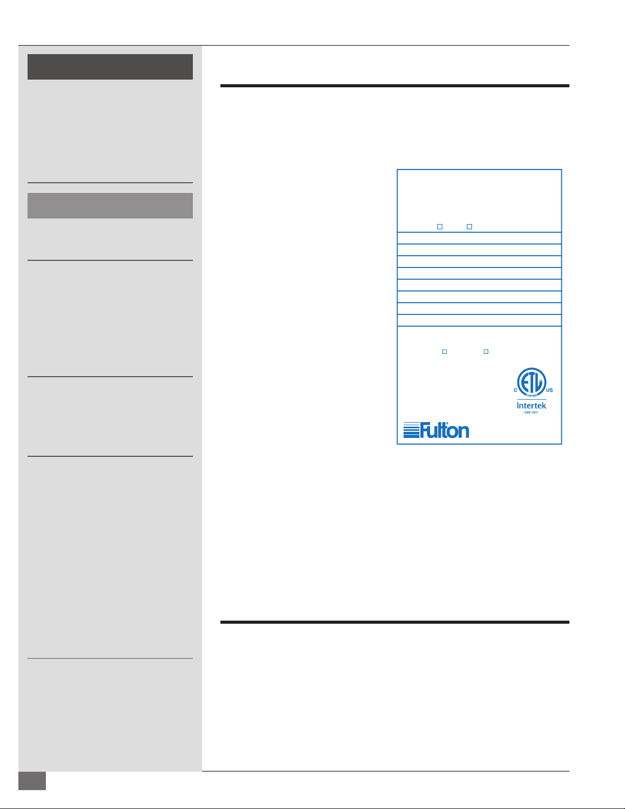
This Boiler is a Direct Vent Boiler for
Installations on Non-Combustible Floors Only
Fulton Gas Fired
Pulse Combustion Boiler
Manufactured by
Fulton Heating Solutions, Inc.
Pulaski, New York 13142
Maximum Gas Supply Pressure: 14 Inches W.C.
Minimum Permissible Gas Supply Pressure for Purpose of
Input Adjustment: 7 Inches W.C. 11 Inches W.C.
Electrical Ratings: 120 V/60 Hz/Less than 15 Amps
Conforms to ANSI Std. Z21.13 __________
Certified to CSA Std. 4.9__________
Wall Thickness Through Which Vent System May
Be Installed: 3
1
/
4
Inches Min. / 20 Inches Max.
Minimum Clearance to Combustibles:
1 Inch (Sides) / 24 Inches (Top, Front & Rear)
Type of Gas:
Natural Propane
Boiler Model No.
Boiler National Board No.
Year
Min. BTU Input/Hr. Min. BTU Output/Hr.
Max. BTU Input/Hr. Max. BTU Output/Hr.
Design Pressure PSI
Mimimum Relief Valve Capacity: Pounds/Hr.
Manifold Gas Pressure: Inches W.C.
FIGURE 1 PULSE BOILER PLATE

Questions? Call (315) 298-5121, or visit us online at www.fulton.com
SECTION 2 PHW-IOM-2013-0214 INSTALLATION
2-3
} STANDARD TRIM
The following items are standard trim for Fulton Pulse Combustion Hydronic
Boilers:
§ Microprocessor Based Control - 120 volt with built-in operating and high
limit controls, and separately wired dual element sensor
§ Low Water Cuto (Probe Type)
§ Control Panel Completely Wired with Diagram
§ Gas Pressure Switches
§ Spark Ignition
§ Factory-Assembled and Mounted Fuel Train
§ Flame Rod
} PACKAGED SEPARATELY
Included with and packaged separately with each boiler are the following
components:
§ ASME Pressure Relief Valve
§ Pressure-Temperature Gauge
§ Air Intake Pipe Adaptor
§ Installation, Operation, and Maintenance Manual
§ Elastomer Coated Fiberglass Cubes or Springs For Mounting
§ Gas and Water Flex Connectors
§ Intake and Exhaust Mu ers
§ 1 Can Touch-up Paint
} OTHER ACCESSORIES
Other items that may be included are:
§ Condensate Drain - one condensate drain kit can accommodate the
condensate from up to 12 MM BTUs.
§ PH Neutralization Kit
Placement & Rigging
Proper placement of your Fulton product is essential. Correct placement is the
rst step to trouble-free installation, operation, and maintenance.
Adhere to the following for placement and rigging:
1. Check building speci cations for permissible oor loading. Use Table 1 for
unit reference.
2. Conform to all the requirements of all national, state and local codes
established by the authorities having jurisdiction and/or the U.S. to the
National Fuel Gas Code, latest edition. Authorities having jurisdiction
should be consulted before installations are made. Where required by local
codes, the installation must conform to American Society of Mechanical
Engineers Safety Code for Controls and Safety Devices for Automatically
Fired Boilers (ASME CSD-1).
3. Since an external electrical source is utilized, the boiler, when installed,
must be electrically ground in accordance with the National Electric Code,
! WARNING
All information in this manual is for
reference and guidance purposes,
and does not substitute for required
professional training, conduct, and strict
adherence to applicable jurisdictional/
professional codes and regulations.
Competent personnel in accordance
with all applicable local codes should
carry out the installation of the Fulton
equipment. All state and jurisdictional
codes beyond the scope of the applicable
ASME Boiler and Pressure Vessel Codes,
for its corresponding classi cation, should
be followed in all cases. Jurisdictional
authorities must be consulted prior to
installation.
A competent rigger experienced in
handling heavy equipment should handle
rigging your equipment into position.
The equipment must be installed on a
non-combustible surface.
Failure to provide required and safe
access to the equipment could impede
commissioning and maintenance.
Service technicians are instructed not to
commence commissioning if hazardous
conditions exist.
Failure to provide proper minimum
clearances between equipment and
combustible materials may result in re.
4 CAUTION
Do not allow weight to bear on equipment
components to prevent damage.
© The Fulton Companies 2013
INSTALLATION PHW-IOM-2013-0214 SECTION 2
2-4
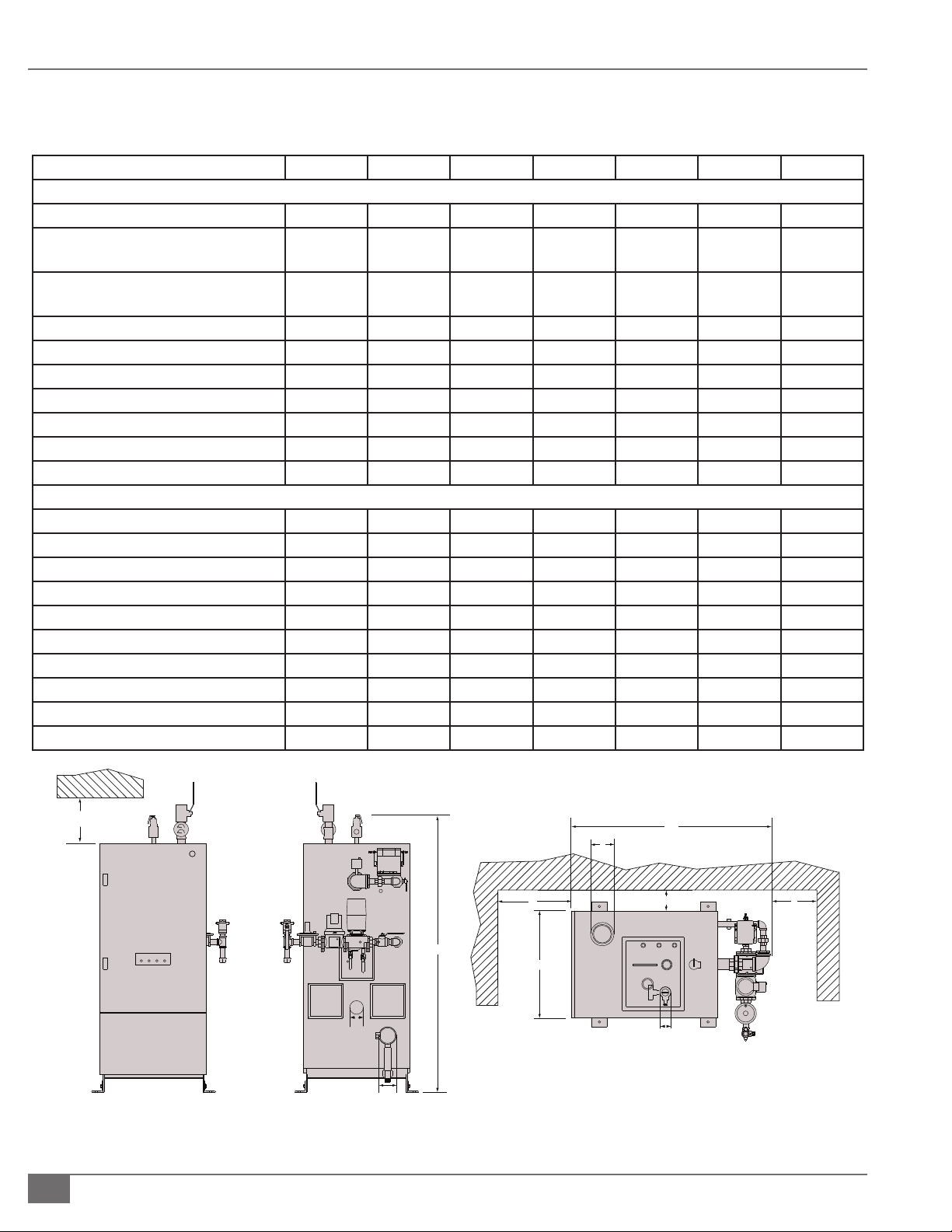
TABLE 1 - BOILER DIMENSIONS AND OPERATING REQUIREMENTS
Model PHW 300 500 750 1000 1400 2000
Speci cations
Input BTU/Hr 300,000 500,000 750,000 1,000,000 1,400,000 2,000,000
Nat. Gas consumption @ rated
capacity
FT3/Hr 300 500 750 1000 1400 2000
Propane Consumption @rated
capacity
FT3/Hr 120 200 300 400 560 720
Electrical Requirements 120V/60/1 4.2/0.6 4.2/0.6 4.2/0.6 4.2/0.6 4.2/0.6 10/.75
(Amps: Max/Run)
240V/60/1 2.1/0.3 2.1/0.3 2.1/0.3 2.1/0.3 2.1/0.3 5/0.4
MAWP PSI 160 160 160 160 160 160
BAR 4.1/11.0 4.1/11.0 4.1/11.0 4.1/11.0 4.1/11.0 4.1/11.0
Water Content Gal 34 34 42 42 80 75
Dry Weight LB 1395 1395 1800 1800 2230 2900
Operating Weight LB 1680 1680 2150 2150 3195 3500
Dimensions
A. Boiler Width IN 27.5 27.5 27.5 27.5 33.6 33.6
B. Overall Boiler Height IN 71.25 71.25 83.2 83.2 88.1 89
C. Overall Boiler Depth IN 53.25 53.25 51.3 51.3 62.6 70.1
D. Exhaust Outlet Diameter IN 4 4 4 4 4 6
E. Air Inlet Diameter IN 3 3 4 4 4 6
F. Water Inlet/ Outlet Diameter IN 2 2 2 2 2.5 4 Flanged
G. Min. Clearance to Ceiling IN 24 24 24 24 24 24
H. Min. Clearance to Either Side Wall IN 1 1 1 1 1 1
I. Min. Clearance in Front of Boiler IN 36 36 36 36 36 36
J. Min. Clearance Behind Boiler IN 24 24 24 24 24 24
FIGURE 2 -PULSE COMBUSTION HYDRONIC BOILER
Back View
Front View
Top View
A
C
D
B
G
E
H
F
F
I J

Questions? Call (315) 298-5121, or visit us online at www.fulton.com
SECTION 2 PHW-IOM-2013-0214 INSTALLATION
2-5
American National Standards Institute (ANSI) National Fire Protection
Association (NFPA) 70, latest edition.
4. Install so that all system components are protected from water (dripping,
spraying, rain, etc.) during boiler operation and service.
5. Install on a level, non-combustible surface in the vertical position. Concrete
is strongly recommended.
6. Provide combustion and ventilation air in accordance with applicable
provisions of local building codes or: USA – NFPA 54/ANSI Z223.1, Section
5.3, Air for Combustion and Ventilation.
7. Locate the boiler so that the air supply and exhaust piping between
the boiler and outside wall/roof are within length or pressure drop
requirements. See Clearances and Serviceability section of this manual.
Clearances and Serviceability
Adhere to the following for clearances and serviceability:
1. All local and national codes (NFPA, ANSI, UL, ETL, ASME, CSA) must be
followed for proper clearances and serviceability for your boiler or heater.
Authorities having jurisdiction should be consulted before installations are
made.
2. Appropriate front, back, side and top clearances must be maintained
(Figure 2, Table 1). This will allow access around the equipment to facilitate
maintenance and a safe work environment. An 1 inch (25.4 mm) side
clearance is acceptable between boilers. Custom con gurations may not
allow 1 inch (25.4 mm) side clearance.
3. Ensure all labels on the boiler will be fully visible for maintenance and
inspection.
Install Isolation Mounts
All pulse combustion boilers must be installed with vibration isolators. No
pulse combustion boiler shall be lagged directly to the concrete oor due to
the transfer of vibration. For installations near “sensitive” areas such as o ces,
classrooms, or hospital rooms, spring mounts - which t under the corner of each
boiler - must be used instead of the cubes.
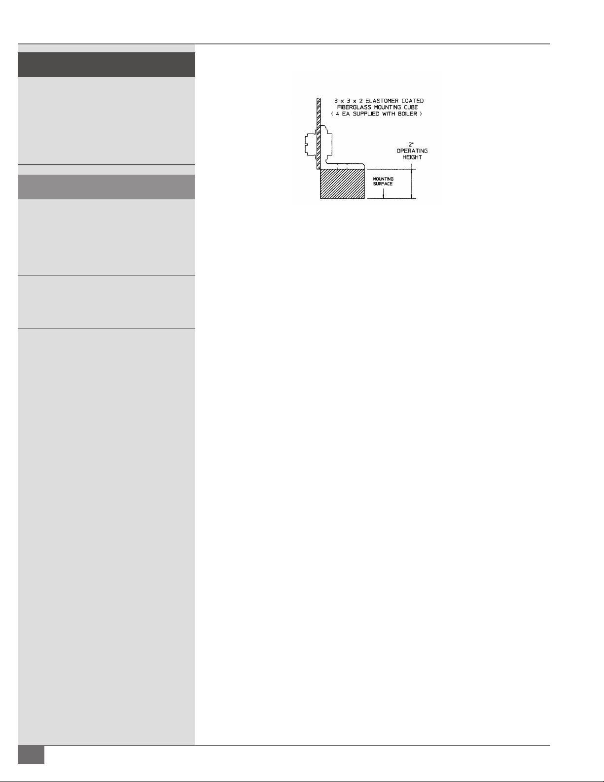
¡ How to Install Elastomer Cube Isolation Mounts
Adhere to the following for elastomer cube isolation mounts (see Figure 3):
1. Locate in the box of trim shipped with each Pulse boiler the 4 elastomer
cubes (3” x 3” x 2”) used for vibration isolation.
2. Insert these cubes under each foot of the boiler.
! WARNING
Do not install this boiler in an uncontrolled
environment where condensate will be
subject to freezing temperatures.
4 CAUTION
Do not install this boiler on carpeting.
Install boiler such that gas ignition system
components are protected from water
(dripping, spraying, rain, etc.) during boiler
operation and service.
© The Fulton Companies 2013
INSTALLATION PHW-IOM-2013-0214 SECTION 2
2-6
NOTE: ´ Flex connectors must be installed on the gas supply, water inlet and
water outlet lines. Spring loaded pipe hangers should be used on the air
inlet and the ue gas vent.
NOTE: ´ Contact your Fulton Representative for vibration isolation packages
designed speci cally for your application.
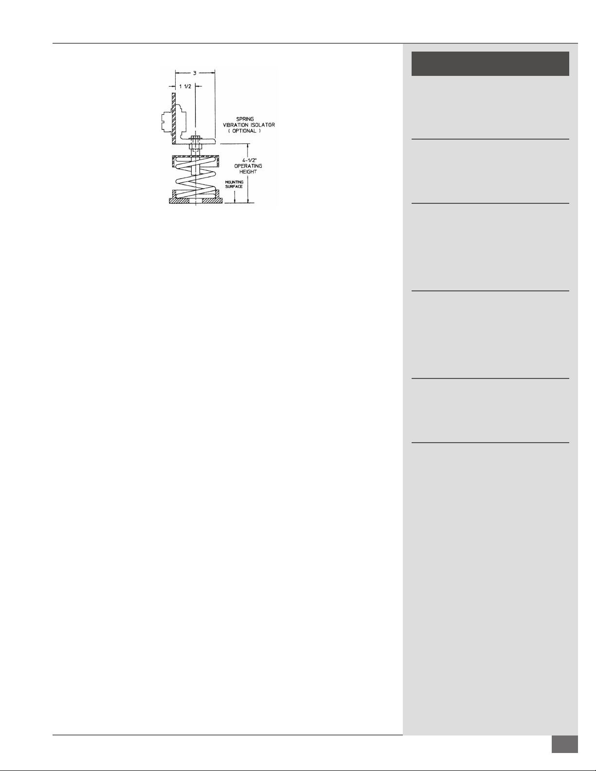
¡ How to Install Spring Isolation Mounts
Adhere to the following for Spring Isolation Mounts (see Figure 4):
1. Thread the leveling bolt into the top load plate of the spring until the head
of the bolt is within 1/8” of the top load plate of the spring.
2. Coordinate the location of each isolator.
3. Remove the small cap screw and washer. Raise the boiler with jacks or
similar tools. Do not attempt to raise the boiler via one lifting point, but lift
evenly around the perimeter of the boiler). Slide the spring isolator under
the boiler or mounting bracket with the bolt head on the underside of the
bracket.
4. Insert the small cap screw through the bracket and thread into the top of
the leveling bolt and tighten nger tight.
5. Lower the boiler (evenly) onto the spring isolators. Do not overload any
one isolator and take care not to push the boiler sideways.
6. Do not attempt to place all the weight on one spring, but distribute the
load proportionately by adjusting each isolator in sequence.
7. Continue to adjust each leveling bolt (in sequence) until the boiler is at
its proper height. When the boiler is lled with water, the springs will
compress approximately 1-2”.
8. Tighten the small cap screw, thus securing the spring isolator to the
supported equipment and locking the leveling bolt against turning.
! WARNING
All information in this manual is for
reference and guidance purposes,
and does not substitute for required
professional training, conduct, and strict
adherence to applicable jurisdictional/
professional codes and regulations.
4 CAUTION
Do not attempt to move the boiler laterally
while it is supported on isolators. Bent or
broken leveling bolts or springs, or damage
to the neoprene bottom spring cap could
result.
Do not install the boiler in an uncontrolled
environment where the condensate will be
subject to freezing temperatures.
FIGURE 3 - INSTALLING ELASTOMER CUBE ISOLATION MOUNTS
Questions? Call (315) 298-5121, or visit us online at www.fulton.com
SECTION 2 PHW-IOM-2013-0214 INSTALLATION
2-7
! WARNING
The discharge from the safety relief
valve must be arranged to ensure
no danger of scalding personnel, or
equipment damage.
Provisions must be made to properly
pipe the safety relief discharge
away from the boiler to the point of
discharge.
The hydronic system should never be
ushed while the boiler is attached
to the system since the debris could
accumulate in the boiler and block
water from passing through the heat
exchanger.
Ensure all labels on the boiler are
legible. All connections and safety
devices, both mechanical and
electrical, must be kept clean, with
ease of access for inspection, use and
maintenance.
Do not store or use gasoline or other
ammable vapors and liquids or
corrosive materials in the vicinity of
this or any other appliances.
NOTE: ´ Do not attempt to move the boiler laterally while it is supported
on the isolators. If it is necessary to move the boiler remove the weight
from the isolators by raising the boiler before moving. Failure to follow
this procedure could result in bent or broken leveling bolts or springs, or
damage to the neoprene bottom spring cap.
¡ How to Install Seismic Spring Isolation Mounts
Adhere to the following for installation of Seismic Spring Isolation Mounts (see
Figure 5):
1. Thread the leveling bolt 1/2” into the top of the load cap.
2. Remove the lock nut and one washer from the top of the leveling bolt.
Locate leveling nut as far down on leveling bolt as it will travel.
3. Coordinate the location of each isolator.
4. Place a one inch shim next to each bracket between the boiler and the
housekeeping pad or structural oor. If an operating clearance of other
than one inch is desired, use an appropriate size shim.
5. Raise the boiler and slide the spring isolator under the equipment
mounting bracket with the leveling nut and one washer on the under side
of the bracket.
6. Lower the boiler onto the spring isolators taking care not to overload any
one isolator and taking care not to push the boiler sideways.
7. Install second washer and lock nut one inch down from top of leveling
bolt.
8. Turn the leveling nut in a counter-clockwise rotation until the boiler
just touches the shim. The shim may now be removed. Proceed with
adjustment of the other three isolators.
9. Tighten the lock nuts on the leveling bolts, thus bolting the spring to the
boiler and locking the leveling bolt against turning.
FIGURE 4 - INSTALLING SPRING ISOLATION MOUNTS

© The Fulton Companies 2013
INSTALLATION PHW-IOM-2013-0214 SECTION 2
2-8
! WARNING
Discharge from the safety relief valve
must be arranged so that there is no
danger of scalding. When the safety
relief valve is piped away from the
boiler to the point of discharge, there
must be provisions to properly drain
the piping.
No shuto of any kind may be placed
between the safety relief valve and
the boiler, or on the discharge pipe
between the safety relief valve and
the atmosphere. Doing so may
cause an accidental explosion from
overpressure.
4 CAUTION
Care needs to be taken to eliminate
oxygen from the water system, as
excess oxygen in the system will
reduce the life of any boiler. The
boiler warranty does not cover heat
exchanger replacement due to oxygen
contamination of boiler water.
Heat exchanger failure due to
inappropriate water quality, foreign
matter or debris damage is not covered
under the warranty.
If the piping system attached to this
unit will be chemically cleaned, the
boiler must be disconnected from the
system and a bypass installed so that
the chemical cleaning solution does
not circulate through the boiler.
NOTE: ´ Do not attempt to move the isolators laterally with the weight of the
boiler on them. If it is necessary to move the boiler, remove the weight from
the isolators by raising the equipment before moving.
Install Boiler Trim
Each boiler is supplied with a safety relief valve sized in accordance with ASME
requirements.
Adhere to the following for installation:
1. Connect the safety relief valve to the coupling located in the top of the
boiler. The safety relief valve must be installed with a 6” nipple (8” for
PHW2000) between the boiler and the safety valve. The safety relief valve
must always be installed in the vertical position. The discharge pipe shall
be not less than the full area of the valve outlet. The discharge pipe shall be
as short and straight as possible and so arranged as to avoid undue stress
on the valve.
2. Install pressure-temperature gauge in the side port of a tee installed in the
boiler water outlet. A tee is installed on the nipple.
Water Chemistry Requirements
All water supplies contain some amount of solids, dissolved gases and dissolved
minerals. These materials may promote corrosion, deposition and/or fouling
of equipment. To prevent these contaminants from impacting on boiler
performance, valve operation and general pipe longevity, each location must be
analyzed and treated accordingly. The following are installation recommendations
for “closed-loop” recirculating hot water heating systems.
1. Automatic pressure activated water make up valve with back ow preventer
providing water to the system, not fed directly to the boiler, set to maintain:
§ Required NPSH for recirculating pump(s).
FIGURE 5 - INSTALLING SEISMIC SPRING ISOLATION MOUNTS
Questions? Call (315) 298-5121, or visit us online at www.fulton.com
SECTION 2 PHW-IOM-2013-0214 INSTALLATION
2-9
§ A positive system pressure at the highest point of 5 to
10 psi.
§ Make up water valve should be designed to add water
to the system at the outlet of the boiler and should
not be fed directly into the boiler.
2. Air removal equipment, including air separator and
automatic air breather valves.
3. A functioning expansion tank designed to system
speci cations.
4. Filtration to remove particulates installed inline with the
suction side of the recirculating pump.
5. Bypass chemical feeder for corrosion inhibitor
maintenance.
6. Optionally a water meter could be installed in series
with the automatic pressure activated water make up
valve to monitor any make up water.
7. Ensure water quality meets the following:
§ Oxygen - less than 250 ppb (operating condition)
§ pH - must be in the range of 8-10
§ Total Iron & Copper - less than 25 ppm
§ Corrosion Inhibitor - level capable of maintaining
iron corrosion rates < 2 mpy. Due to changing
environmental restrictions, a non-heavy metal, all
organic inhibitor is recommended, which is designed
for multi-metal systems including ferrous metals and
yellow metals such as copper and brass.
§ Chlorides - less than 250 ppm as Cl. Limit applicable
only to installations utilizing duplex steel pressure
vessel components.
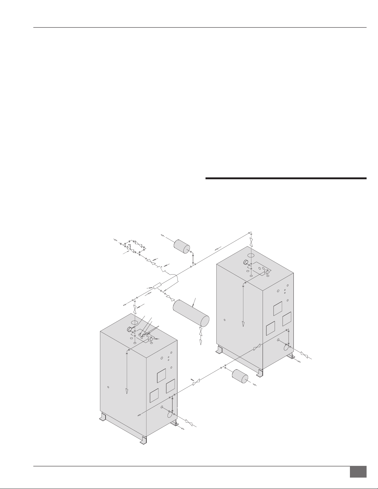
Install Water Piping
The bottom connection to the boiler is the INLET and must be
connected as the return from the system. The top connection
on the boiler is the OUTLET and must be connected as the
supply to the system.
ADDITONAL
BOILER (S)
HEATING
SUPPLY
MANIFOLD
ADDITIONAL
BOILER (S)
HOT WATER
STOP VALVE
TEMPERATURE
PRESSURE
GAUGE
OPERATING AND
HIGH LIMIT AQUASTATS
(INTERNAL)
ASME
SAFETY
VALVE
STOP
VALVE
DRAIN
CONDENSATE
DRAIN
Multiple Boiler Installation
TYPICAL PIPING SYSTEM
UNLESS OTHERWISE NOTED, ALL
COMPONENTS SHOWN ARE TYPICAL
ON EACH BOILER
HEATING
RETURN
MANIFOLD
EXPANSION
TANK
STOP
VALVE
CHECK
VALVE
PRESSURE
REDUCING
VALVE
MAKEUP
WATER
AUTOMATIC
AIR VENT
FLAME ROD
SPARK PLUG
FIGURE 6 - TYPICAL PIPING (MULTIPLE BOILER SYSTEM)

© The Fulton Companies 2013
INSTALLATION PHW-IOM-2013-0214 SECTION 2
2-10
Adhere to the following for water piping installation (Figure 6):
1. Connect hot water supply to heating system feed line.
2. Connect expansion tank.
3. Connect return water to boiler return water connection.
4. Install an air separator and air eliminator (air vent) which is necessary as
there is no built in boiler air eliminating feature.
5. If a sealed diaphragm-type expansion tank is used, install air eliminator in
hot water piping at air separator.
6. If an air cushion type expansion tank is used, pipe tank directly into boiler
supply.
7. On multi zoned systems (or a system with both space and domestic water
heating), air elimination must be provided either in the common piping or
every loop. When the boiler is installed at a higher level than baseboard
radiation, air elimination must be provided directly above the unit.
8. Install hot water circulator, remote mounted from boiler. Do not attach
directly to the boiler. Flexible connectors must be placed between the
circulator and the boiler.
NOTE: ´ For all models, a no ow condition will not damage the heat
exchanger, however, adequate ow should be provided to prevent tripping
the boiler on high temperature limit.
9. For boilers with carbon steel or duplex steel heat exchangers, the
maximum allowable temperature di erential across the heat exchanger
is 100 degrees F. Minimum outlet temperature for carbon steel units must
be 120 degrees F or greater. Maximum allowable working temperature for
carbon steel units is 240 F. High limit is set at 230 F, therefore operating at
a temperature greater than 220 F is not recommended. For duplex steel
units, maximum allowable working temperature is 210 F. High limit is set
at 200 F, therefore operating at a temperature greater than 190 F is not
recommended.
10. Install manual purging valves in all loops and zones. Install pressure
reducing (automatic ll) valve in the cold water ll line to the boiler system.
11. Check that the proposed operation of zone valves, zone circulator(s) and
diverting valves will not isolate air separator(s) and/ or expansion tank(s)
from the boiler.
12. Clearance from hot water pipes to combustibles must be at least 6”.
13. The boiler, when used in conjunction with a refrigeration system, must
be installed so the chilled medium is piped in parallel with the boiler
with appropriate valves to prevent the chilled medium from entering the
boiler. If the boilers are connected to heating coils, located in air handling
units where they may be exposed to refrigerated air circulation, such
boiler piping systems shall be equipped with ow control valves or other
automatic means to prevent gravity circulation of the boiler water during
! WARNING
All information in this manual is for
reference and guidance purposes,
and does not substitute for required
professional training, conduct, and strict
adherence to applicable jurisdictional/
professional codes and regulations.
Do not use matches, candles, ame or
other sources of ignition to check for gas
leaks.
If the water supply must be temporarily
disconnected from the condensate
trap, the boilers must be turned o to
prevent accidental ue gas emission
into the boiler room. An uninterruptible
water supply is required and shall be
connected to the ¼” compression tting
on the condensate drain. The water supply
maintains a water level in the drain kit to
prevent accidental ue gas emission into
the boiler room.
Cements for plastic pipe are ammable
liquids and should be kept away from all
sources of ignition. Proper ventilation
should be maintained to reduce the
hazard and to minimize breathing of
cement vapors. Avoid contact of cement
with skin and eyes.
4 CAUTION
Some soap used for leak testing is corrosive
to certain types of metals. Clean all piping
thoroughly after completing the leak check.

Questions? Call (315) 298-5121, or visit us online at www.fulton.com
SECTION 2 PHW-IOM-2013-0214 INSTALLATION
2-11
the cooling cycle.
14. The boiler is furnished with a probe type low water
cuto . No eld piping is required. If the probe does
not sense water, the boiler will shut down and a red
indicator will be illuminated on the control panel.
15. The boiler is not provided with external drain
connections. A drain valve must be installed near the
inlet connection to the boiler and piped to a suitable
oor drain. A Boiler Drain Assembly can also be
purchased from Fulton. This Boiler Drain Assembly must
be installed near the inlet connection to the boiler.
16. Before lling the boiler clean and ush the system
to remove any debris. Clean and ush old piping
thoroughly before installing the boiler. Consider
installing a strainer ahead of the boiler.
Install Condensate Drain
The condensate drain kit is intended for use with any size
Pulse unit supplied by Fulton. The 3/4” condensate drain on
the pulse unit will be connected to the 1” inlet on the drain
kit. One or more drain lines may be connected to this inlet
(maximum of 12 MM BTU/hr) through a common header. See
Figure 7.
Adhere to the following for installation:
1. An uninterruptable water supply is required and shall
be connected to the 1/4” compression tting on the
drain oat. The water supply maintains a water level in
the drain kit to prevent the ue gas from entering the
boiler room through the condensate connection. The 1
1/2” connection shall be piped to an appropriate drain
for disposal. If the water supply must be temporarily
disconnected, the boiler(s) must be turned o to
prevent accidental ue gas emission into the boiler
room.
2. Keep the cover on at all times, except during
maintenance of the drain. This drain should be
monitored and checked regularly in your Pulse
maintenance schedule.
3. A condensate collecting tank and condensate pump
FIGURE 7 - MULTIPLE BOILER CONDENSATE DRAIN INSTALLATION

© The Fulton Companies 2013
INSTALLATION PHW-IOM-2013-0214 SECTION 2
2-12
will be required if a oor drain is not available to discharge to (Collecting
tank and pump are not supplied with the boiler). Complete condensate
drain kits are available from Fulton.
¡ Install Condensate Drain Piping
Adhere to the following when installing condensate drain piping:
1. All piping must be galvanized or stainless steel and should be free of leaks.
2. Make sure either elastomer coated berglass cubes or spring mounts have
been installed under each leg of the boiler.
3. Install the condensate piping to the condensate drain in the lower right
hand side of the boiler.
4. Connect 3/4” condensate drain(s) to the 1” header connected in a manifold.
The header must be at least 5 ½” below the condensate outlet of the
individual boiler and must remain ooded by being at least 5 ½” below the
outlet of the condensate drain trap..
5. Connect 1½” drain outlet to an appropriate waste line following applicable
codes. The 1½” drain connection on the condensate drain must be the
highest point prior to going to the drain. Failure to keep drain piping lower
than this point will result in over ow of the condensate drain. Slope the
drain pipe away at a minimum pitch of 1” for every 12 feet.
6. Attach a 1/4” water supply to the compression tting on the oat. The
water line must be connected to an uninterruptible supply. Fulton
recommends connecting it before the “Fast-Fill” valve to the boiler supply
but after the back ow preventer to avoid contamination of a potable
water supply. Maximum allowable water pressure to the compression
tting is 100 PSI.
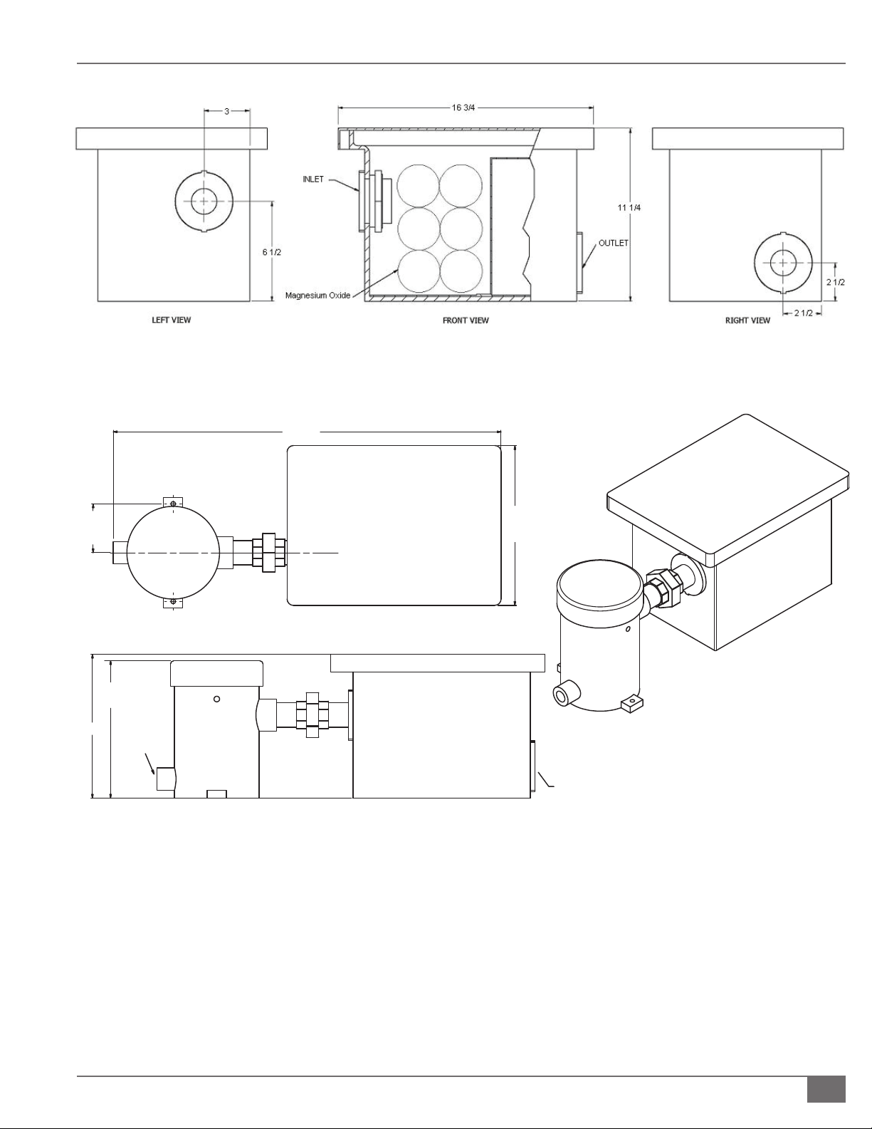
Install pH Neutralization Kit
The pH Neutralization Kit is a Fulton-provided kit designed to bring the pH level
of the boiler’s condensate to a neutral level. It is not a replacement or alternative
for the Condensate Drain Trap. See Figure 8.
Adhere to the following for installation:
1. Use stainless or galvanized pipe and ttings to connect condensate drain
to kit.
2. Connect kit downstream of Condensate Drain Trap. See Figure 9.
3. Pipe outlet to appropriate drain.
NOTE: ´ Replacement bags are available from the Fulton Parts Department.
The medium in the container will neutralize the condensate of 12 MM Btu’s
for approximately 6 months.
! WARNING
All information in this manual is for
reference and guidance purposes,
and does not substitute for required
professional training, conduct,
and strict adherence to applicable
jurisdictional/professional codes and
regulations.
DO NOT USE GASOLINE, CRANKCASE
OIL OR ANY OIL CONTAINING
GASOLINE. If in doubt, contact
your Fulton representative prior to
operation.
Do not store or use gasoline or other
ammable vapors and liquids or
corrosive materials in the vicinity of
this or any other appliances. Cements
for plastic pipe should be kept away
from all sources of ignition. Proper
ventilation should be maintained to
reduce the hazard and to minimize
breathing of cement vapors.
Do not attempt to start boiler to test
wiring before lling and purging the
boiler. A dry re will seriously damage
the boiler and may result in property
damage or personnel injury and is
not covered by warranty.
4 CAUTION
The vent line connection on the gas
pressure regulator must be piped in
accordance with National Fuel Gas
code, latest addenda. In Canada, gas
installations must be in accordance
with current CAN/CGA, and/or local
codes.
Questions? Call (315) 298-5121, or visit us online at www.fulton.com
SECTION 2 PHW-IOM-2013-0214 INSTALLATION
2-13
FIGURE 8 - FULTON PH NEUTRALIZING KIT (WITHOUT PUMP)
FIGURE 9 - FIELD CONNECTIONS FOR CONDENSATE DRAIN TO PH NEUTRALIZATION TANK
TOP VIEW
30 3/8
[771]
12 1/2
[318]
3 13/16
[97]
(TYP.)
FRONT VIEW
1 1/2" PLASTIC FITTING
CONNECTION TO DRAIN
1" NPT
CONNECTION
TO BOILER
10 3/4
[273]
11 1/4
[286]
ISOMETRIC VIEW
© The Fulton Companies 2013
INSTALLATION PHW-IOM-2013-0214 SECTION 2
2-14
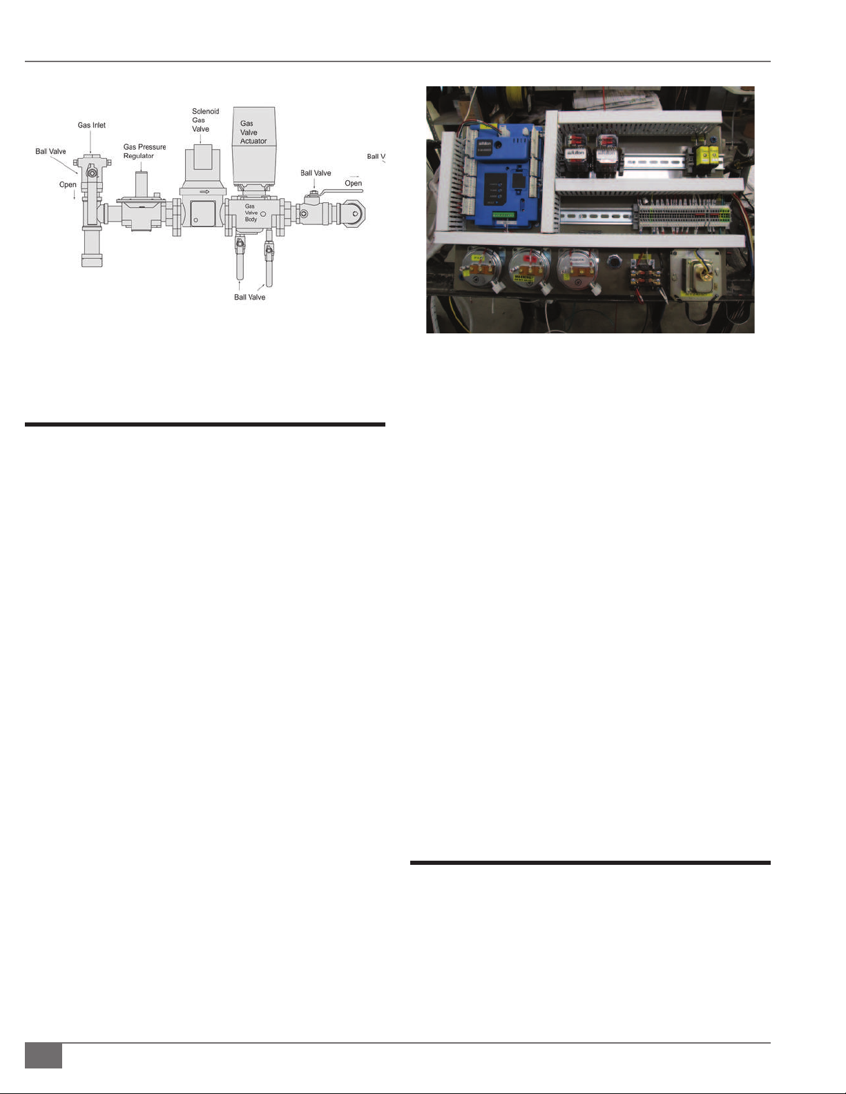
Install Gas Piping
Adhere to the following for gas piping installation:
1. Gas Piping should be installed in accordance with
National Fuel Gas Code, ANSI Z223 1 1991 or latest
addenda and any other local codes which may apply.
In Canada gas installations must be in accordance with
the current CAN/CGA B149.1 and .2 and/or local codes.
2. The pipe and the ttings used should be new and free
of dirt or other deposits. Piping must be of the proper
size to insure adequate gas supply.
NOTE: ´ Do not use the boiler’s gas train inlet size as a
gauge for inlet piping size. Always refer to appropriate
gas piping charts.
NOTE: ´ Full port ball valves approved for gas should be
used for gas isolation to reduce pressure drop.
3. Gas pressure to inlet of gas train should be 7” WC for
natural gas and 11” WC for propane (PHW2000LE
requires 11”WC on natural gas). Connect gas supply
line to the open end of the tee on which the drip leg is
installed. See Figure 10.
4. When making gas piping joints, use a sealing
compound resistant to the action of lique ed
petroleum gases. Do not use Te on tape on gas line
threads.
5. After gas piping is completed and before wiring
installation is started, carefully check all piping
connections, (factory and eld), for gas leaks. Use a soap
and water solution.
6. The boiler must be isolated from the gas supply piping
system by closing its individual manual shut o valve
during any pressure testing of the gas supply system at
more than 1/2psi (3.5kPa).
7. Gas vents to outdoor air must be provided for the gas
pressure regulator. Restricting ori ces or bleed ori ces
should not be used at anytime. The vent line connection
on the gas pressure regulator must be piped to outdoor
air by installer in accordance with the National Fuel Gas
Code, ANSI Z223- 1-1991 or latest addenda.
8. In Canada gas installations must be in accordance with
the current CAN/CGA B149.1 and .2 and/or local codes.
} HONEYWELL PRESSURE SWITCH
The Honeywell C6097 pressure switch is designed with
internal vent limiters to meet UL 353 requirements and are
CSA certi ed, UL listed, FM approved, and CSD-1 acceptable.
Local codes may not permit a gas device (pressure switch)
without an external vent line connection. If that is the case, a
vent line must be added.
Install Field Wiring
Adhere to the following for eld wiring installation (see
Figures 11 and 52):
1. An independent power supply line is recommended
for the boiler. Connect one 120 volt (60Hz) fused power
line to terminal block to hot, or marked terminal per
electrical diagram. Connect applicable wires to neutral
and ground. Connect a ground wire to green colored
ground lug in electrical control box.
FIGURE 10 - GAS VALVE CONFIGURATION
FIGURE 11 - FIELD WIRING

Questions? Call (315) 298-5121, or visit us online at www.fulton.com
SECTION 2 PHW-IOM-2013-0214 INSTALLATION
2-15
! WARNING
All information in this manual is for
reference and guidance purposes,
and does not substitute for required
professional training, conduct,
and strict adherence to applicable
jurisdictional/professional codes and
regulations.
Do not attempt to start boiler to test
wiring before lling and purging the
boiler. A dry re may cause injury,
boiler damage, and/or property
damage, and is not covered by
warranty.
Do not use the boiler/burner as
support for ducted air piping.
Ducted piping must be supported
independently of the boiler.
Do not terminate venting into an
enclosed area.
Never use open ame or smoke from
a cigarette, cigar, or pipe as a testing
method during boiler installation,
operation, or maintenance.
Foreign substances, such as
combustible volatiles in the
combustion system can create
hazardous conditions. If foreign
substances can enter the air stream,
the boiler combustion air inlet must
be piped to an outside location.
Particulate matter or chemicals in the
combustion air supply to the boiler
will cause damage to air apper
gaskets, could cause the unit to fail
to light, and is not covered under
warranty.
2. Ensure gas ignition system components are protected from water
(dripping, spraying, rain, etc.) during boiler operation and service.
3. Any attempt to start the boiler to test wiring prior to lling and purging
may result in a dry re and void the warranty.
Air Intake Supply Piping Installation Preparation
The boiler is equipped with air intake supply and exhaust vent connections
located at the top and rear of the boiler respectively. See Figure 12. Air supply
is on the top. For Models PHW300 and PHW500 these connections are 3” NPT
threaded female ttings and for Models PHW750, PHW950, PHW1000, and
PHW1400 they are 4” NPT thread female ttings. These ttings will accept 3” and
4” male/female pipe to tubing adaptors respectively. Model PHW2000 has 6”
NPT threaded female tting. In supporting piping, or routing it through a rafter
or wall, always use vibration eliminating hangers around the piping to prevent
vibration transmission. Always avoid rigid connections between piping and
structural members of the building.
1. For sealed combustion applications, air intake must be piped out of the
building. Air Intake pipes and ttings for all models shall be Schedule 40
PVC pipe. All Schedule 40 PVC pipe, ttings, primer and cement must
conform with American National Standard Institute and the American
Society for Testing and Materials (ANSI/ASTM standards).
2. For applications using make up air from the boiler room, a minimum of 10’
of venting including the intake mu er must be installed. Per ASME Section
VI Para. 6.04, an unobstructed air ventilation opening should be sized on
the basis of one square inch free area per 2000 BTU/HR maximum fuel
input of the combined burners located in the boiler room. This is subject to
state and local regulations. The installation of exhaust fans in a boiler room
is not recommended.
FIGURE 12 - AIR INLET LOCATION
© The Fulton Companies 2013
INSTALLATION PHW-IOM-2013-0214 SECTION 2
2-16
3. All alternative individual venting arrangements must result in an intake
pressure drop not to exceed 2.5” w.c. (Consult factory for assistance.)
4. All common venting arrangements must result in a pressure drop of less
than 0.1” w.c. in the common header. (Consult factory for assistance.)
NOTE: ´ Intake PVC piping must be assembled using cement. This will ensure
that the intake is air tight and will not allow contaminates from the boiler
room into the boiler. The cement shall be free owing and contain no lumps,
undissolved particles or any foreign matter that adversely a ects the joint
strength or chemical resistance of the cement. The cement shall not show
gelation, strati cation, or separation that cannot be removed by stirring.
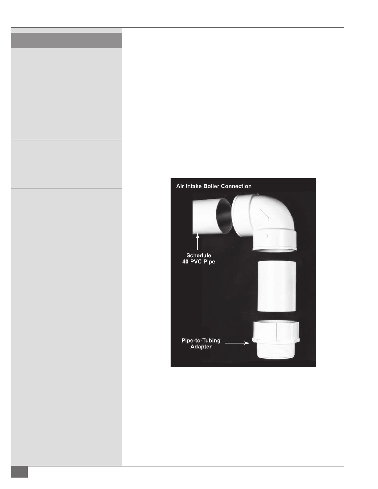
¡ Cementing Joints
Adhere to the following procedure (per ASTM D2855) (see Figure 13):
1. Measure and cut PVC pipe to desired length.
2. Chamfer end of pipe, removing any ridges or rough edges. If end is not
chamfered, the edge of the pipe may remove cement from the tting
socket and result in a leaking joint.
3. Clean and dry surfaces to be joined.
4. Test t joint and mark depth of tting on the pipe.
FIGURE 13 - AIR INTAKE BOILER CONNECTION
4 CAUTION
Intake PVC piping must be assembled using
cement. This ensures that the intake is air
tight and will not allow contaminants
to enter the boiler from the boiler room.
Cement must be free- owing and contain
no lumps, undissolved particles or any
foreign matter that adversely a ects the
joint strength or chemical resistance of the
cement. The cement must show no gelation,
strati cation, or separation that cannot be
removed by stirring.
Cements for plastic pipe are ammable
and should be kept away from all sources
of ignition. Proper ventilation must be
maintained to prevent cement vapor
hazards. Avoid contact with skin and eyes.

Questions? Call (315) 298-5121, or visit us online at www.fulton.com
SECTION 2 PHW-IOM-2013-0214 INSTALLATION
2-17
5. Uniformly apply liberal coat of primer to inside socket surface of tting and
male end of pipe to depth of tting socket.
6. Promptly apply solvent cement to end of pipe and inside socket surface
of tting. Cement should be applied lightly—but uniformly—to inside of
socket. Take care to keep excess cement out of socket. Apply second coat
to pipe end. Time is critical at this stage. Do not allow primer to dry before
applying cement.
7. Immediately after applying last coat of cement to pipe, while inside socket
surface and end of pipe are wet with cement, insert end of pipe into
socket, turn pipe 1/4 turn to distribute cement evenly, continue to insert
pipe until it bottoms out.
NOTE: ´ Assembly should be completed within 20 seconds after last
application of cement. Do not use hammer to insert pipe.
8. After assembly, wipe excess cement from pipe at end of tting socket. A
properly made joint will show a bead around its entire perimeter. Any gaps may
indicate a defective assembly due to insu cient cement.
9. Handle joints carefully until completely set.
Install Intake Muffl er
To install intake mu er, cement joints as indicated in previous section. For
best noise attenuation, the mu er should be installed as close to the boiler
as possible, and can be horizontal or vertical in orientation.
Preparing to Install Exhaust Vent Piping
A Fulton Pulse boiler should not be connected to a common venting system with
other types of gas appliances. Adhere to the following when preparing to install
vent piping:
1. The boiler is equipped with an exhaust vent connection located at the
rear of the boiler. For models PHW300 up through the PHW1400, the
connection is 4” NPT threaded female. Model PHW2000, the connection is
6” NPT threaded female.
2. The exhaust line must be sloped down toward the boiler with a pitch of
at least 1/4” per foot. Failure to do so can result in a condensate pocket
which can result in an inoperative boiler. There must be no low spots in
the exhaust pipe, as this can also result in a condensate pocket. A high spot
is acceptable, provided the pitch from the high spot is maintained back to
the boiler or to the outside point of the exhaust. In supporting piping, or
routing it through a rafter or wall, always use vibration eliminating hangers
around the piping to prevent vibration transmission. Always avoid rigid
connections between piping and structural members of the building.
3. All alternative individual venting arrangements must result in an exhaust
pressure drop not to exceed 2.5” w.c. (Consult factory for assistance.)
! WARNING
All information in this manual is for
reference and guidance purposes,
and does not substitute for required
professional training, conduct, and strict
adherence to applicable jurisdictional/
professional codes and regulations.

© The Fulton Companies 2013
INSTALLATION PHW-IOM-2013-0214 SECTION 2
2-18
4. All common venting arrangements must result in a pressure drop of -0.1”
to 0.0” w.c if not using a draft assist fan. (Consult factory for assistance.)
5. All common venting arrangements must result in a pressure drop of
0.0” to 0.75” w.c. with the use of a draft assist fan. (Consult factory for
assistance.)
6. Variable speed exhaust fan pressure setting should be no more than 0.1”
w.c.
7. Flue vent pipes and ttings for all Pulse boilers must be UL listed for use
with Category IV, positive pressure, condensing equipment. Speci cally
this material is AL294C. Stainless Steel 316L piping is also acceptable.
At 480°F temperature rating, a 5” minimum air space clearance to
combustibles is required. Applicable Federal Codes are NFPA 54/ANSI
Z223.1 National Gas Code and NFPA/ANSI 211 Chimneys, Fireplaces, Vents
and Solid Fuel Burning Appliances. In Canada, refer to the venting section
of CAN/CGA B149.1 and 2. The gas vent installer should be familiar with
these federal codes as well as any local codes and regulations that may
apply. The procedure for adhesive joining stainless steel pipe and ttings
follows:
§ Do not mix stainless steel pipe with galvanized or other alternatives
for the entire length of the system.
§ All joints between sections of the vent connector and the vertical
conduit must be sealed with a high temperature sealant or gasket to
prevent any possible leakage of ue gas.
§ Apply a bead of sealant, about 1/2“ in diameter, completely around
the male (without tabs) end of each conduit section or elbow,
between 1/4” and 3/8” from the end of the section. Also run a similar
sized bead down the seam weld of each section, from the edge of
the pipe to the top of the bulge.
§ Fully insert the male end of the section into the female tting of
the section below. Attach the sections together. Inspect the joint to
ensure that ue gases will not escape. If necessary, apply additional
sealant to any voids. Allow the sealant 24 hours to cure before
operating the boiler.
§ See speci c manufacturers instructions for complete installation
details.
Exhaust Muffl er Installation
Adhere to the following for mu er drain installation:
§ For mu ers installed in the vertical con guration the drain can be
plugged.
§ For mu ers installed in the horizontal con guration, the drain opening
should be at the down slope (6 o’clock) position, and should be piped
to the drain line between the boiler and the condensate drain. For best
sound attenuation, the mu er should be installed as close to the boiler as
possible.
! WARNING
Crystalline silica may be present in
components of this equipment. Exposure
to crystalline silica may pose signi cant
health hazards, including but not limited to
eye and respiratory system damage. Per the
Centers for Disease Control and Prevention
(CDC) and Occupational Safety and Health
Administration (OSHA), appropriate
Personal Protective Equipment must be
worn to minimize exposure to hazardous
substances. Refer to most current guidelines
o ered by the CDC and OSHA for more
information, including Personal Protective
Equipment recommendations.
4 CAUTION
To prevent potential water damage, never
leave an open manual air vent unattended.

Questions? Call (315) 298-5121, or visit us online at www.fulton.com
SECTION 2 PHW-IOM-2013-0214 INSTALLATION
2-19
Air Intake & Exhaust Piping Requirements for the
Pulse Boiler
Adhere to the following for air intake and exhaust piping:
1. Use piping that matches the inlet/outlet connection sizes for the rst 35
feet and 4 elbows closest to the boiler. See Tables 2 and 3.
§ The piping can be extended to 100 feet and 6 elbows by increasing the
pipe size to 6” for the PHW300 - PHW1000, and to 8” for the PHW2000.
§ For the PHW1400, the air intake and exhaust piping must be 4” for the rst
10 feet and then piping must be upsized to 6” for up to 40 feet. If going
beyond 40 feet, instead of upsizing to 6” after the rst 10 feet, upsize to
8”.
§ It is acceptable to extend the piping up to 100 feet and 6 elbows with
proper sizing.
2. A minimum of 10 feet of piping is required on the air intake (even if
taking combustion air from the boiler room) or exhaust. This creates the
appropriate amount of backpressure for pulse combustion to operate
properly.
3. If air intake or exhaust layouts require upsizing, keep the rst 10 feel closest
to the boiler matching the outlet connection size of the boiler.
4. If utilizing a common header pipe for multiple pulse boilers, the pressure
drop across a common intake pipe must be neutral. The pressure drop
across a common vent pipe must be between -0.1 and 0” W.C. if not
utilizing a mechanical draft system.
5. Exhaust runs should, individually, not have pressure drops of more than
3.0” WC. Intake is +2.0”WC.
TABLE 2 - AIR INTAKE PIPING REQUIREMENTS
Model PHW Type Base
Diameter
(inches)
Length (feet) Number of
90-degree
Elbows
300 PVC 3
3
10 minimum
35 maximum
0
4
500 PVC 3
3
10 minimum
35 maximum
0
4
750 PVC 4
4
10 minimum
35 maximum
0
4
1000 PVC 4
4
10 minimum
35 maximum
0
4
1400* PVC 4
6
10 minimum
35 maximum
0
4
2000 PVC 6
6
10 minimum
35 maximum
0
4
! WARNING
All information in this manual is for
reference and guidance purposes,
and does not substitute for required
professional training, conduct, and strict
adherence to applicable jurisdictional/
professional codes and regulations.

© The Fulton Companies 2013
INSTALLATION PHW-IOM-2013-0214 SECTION 2
2-20
TABLE 3 - EXHAUST VENT PIPING REQUIREMENTS
Model PHW Type Base
Diameter
(inches)
Length (feet) Number of
90-degree
Elbows
300 Stainless Steel
AL294C
4
4
10 minimum
35 maximum
0
4
500 Stainless Steel
AL294C
4
4
10 minimum
35 maximum
0
4
750 Stainless Steel
AL294C
4
4
10 minimum
35 maximum
0
4
1000 Stainless Steel
AL294C
4
4
10 minimum
35 maximum
0
4
1400* Stainless Steel
AL294C
4
6
10 minimum
35 maximum
0
4
2000 Stainless Steel
AL294C
6
6
10 minimum
35 maximum
0
4
*A minimum 10 feet of 4 inch air intake and exhaust is required for the PHW-1400. Air
intake and exhaust con gurations over 10 feet in length will require 4 inches for the rst
10 feet from the boiler, and then 6 inches up to an additional 40 feet, and four elbows.
Air Intake Supply and Exhaust Vent Installation
Adhere to the following for air intake supply and exhaust vent installation:
1. Air intake supply and exhaust vent pipes and ttings are suitable for
vertical, through-the-roof or horizontal through-the-wall installation.
The vent system must be installed in accordance with the manufacturer’s
instructions.
2. All vent pipes and ttings must be installed with appropriate air space
clearances to combustibles. These air space clearances apply to indoor or
outdoor vents—whether they are open, enclosed, horizontal or vertical or
pass through oors, walls, roofs, or framed spaces. See Figure 14. The air
space clearances should be observed to joists, studs, sub oors, plywood,
drywall or plaster enclosures, insulating sheathing, rafters, roo ng, and any
other material classed as combustible.
3. The required minimum air space clearances also apply to electrical wires
and any kind of building insulation away from gas vent and out of the
required air space clearance.
4. Vertical runs or vent pipes and ttings passing through oors, ceilings, or
in framed walls must be re stopped at oors and ceilings. The re stop
must close in the area between the outside of the vent and the opening in
the structure. (Figure 15). When passing through a oor or ceiling frame,
provide an opening 5” to 9” air space clearance to vent pipe as applicable.
The re stop ts to the bottom of a framed opening 13 1/4” square. Nail
into the inside of the framed opening through the four holes in the ring.
The re stop is placed on top of a framed opening 14 1/4” square with the
dished position down. Nail the ange to the top of the framing.
! WARNING
Do not attempt to start boiler before
lling and purging boiler heating system.
A dry re will seriously damage the boiler
and may result in property damage or
personnel injury and is not covered by
warranty.
Operating the boiler beyond its design
limits is dangerous and may also cause
boiler damage. Do not attempt to upgrade
boiler performance with unapproved
modi cations.
 Loading...