


Caliber SOLA Gateways

__________________________________________________________
Note: This document is to be used in conjunction with the applicable Installation, Operation, and
Maintenance Manual. Content subject to change without notice.
TABLE OF CONTENTS
Lead/Lag Outdoor Reset Configuration Using Communication Port 2 (second display port)
Stand Alone Boilers Controlled by a Third Party Control
Gateways
Setup for the Sola 7999D display of Com 2 for BMS Communication
Protocol Gateway Setup Guide
BACnet UDP IP / MSTP / Metasys N2 Module: General and Connection Overview
Lonworks Module: General and Connection Overview (Bacnet is the only option for Pulse
boilers)
Module Dipswitch Overview
Module Service Pin (Lonworks Module Only)
Downloading New Configuration Files
Connection Help
Setting the Static IP Address
Temporarily Disabling the Wireless Connection
Connection Troubleshooting
Node Address Setup
Baud Rate Settings
Modbus to Bacnet Pre-Loaded Gateway Points
Lead/Lag Outdoor Reset Configuration Using Communication Port 2 (second
display port)
If the boilers are set up to be lead/lag with outdoor reset, all the communication connections on the
J3 plug of the Sola control will be used. The third party control can be wired to the Sola display on
communication port 2. If requested at the time of the boiler order, the communication port will be
activated at the factory. Only the baud rate may have to be changed in the field. When multiple
boilers are configured for a system for lead/lag outdoor reset, only the master boiler needs to have
_____________________________________________________________________________________
Questions? Call (315) 298-5121 or visit us online at www.fulton.com
©The Fulton Companies 2013
Supplement SOLA-IOM-2013-0220

__________________________________________________________
the third party connection. The lag boiler(s) points that can be viewed through the master are
limited, so please review the Modbus to Bacnet Pre-Loaded Gateway Points that would be in the
master boilers gateway to see if they are sufficient for your application. Please refer to electrical
diagram in manual, which shows wiring connection to the display's communication port 2.
Return to Table of Contents
Stand Alone Boilers Controlled by a Third Party Control
If the boilers are not set up to be lead/lag outdoor reset, a third party control can land the boilers’
connection to J3, MB1 on the Sola control. If this is known at the time the boiler order is entered,
the control will be set up for this type of control. Please refer to electrical diagram in manual for J3,
MB1 connections. The communication wires can be daisy chained to each boiler.
Return to Table of Contents
Gateways
Fulton offers (as an option) a Modbus to Bacnet gateway. The gateway will come pre-programmed
and wired in one, or if desired, all of the boilers. If the boilers are daisy chained together through J3,
MB1, one gateway can be used on the master boiler which will be wired to communication port 2 of
the master display. Please refer to Setup for the Sola 7999D display of Com 2 for BMS
Communication to verify setup or initial setup of Com 2 port.
and set-up instructions.
Note: Although there are many points that are available through Modbus, not all of them should be
considered to be continuously written to, all writes should be on a change only. There are specific
write addresses that will fill an internal Sola control EEPROM that should not be continuously written
to. Also all the information out of the control is in Celsius; this may have to be converted to
Fahrenheit if desired. Firing rate also requires a conversion.
Return to Table of Contents
Setup for the Sola 7999D display of Com 2 for BMS Communication
The following information will help set-up for communication when using a Sola control with a
Protonode Gateway (Modbus to Bacnet).
_____________________________________________________________________________________
Questions? Call (315) 298-5121 or visit us online at www.fulton.com
©The Fulton Companies 2013
Supplement SOLA-IOM-2013-0220

__________________________________________________________
Note: If a Proto node Gateway is being used, it was fully programmed at the Fulton Factory and
should not require any changes on the Sola side. The customer connection side of the gateway may
require dip switch changes for baud rate and the required address. See the end of these instructions
for information on customer gateway setup.
1. From the Home Screen press Setup
2. Then Press Display setup
3. Then press tab Com 2
- Check the Enable box
- Choose baud rate if known or if a Proto Node Gateway is being used it should be 19,200
- Press the save button
4. Then press the Gateway tab
- Check Enable Modbus gateway
- Press Gateway on COM2 Port
- Press Save
5. Press the upper right Arrow to back out
6. Press Control Setup
7. Press Change Address
8. Password "sola" is required
- Change the address to the required address
o If Protonode is used, Com 1 will be preset to address 2 on all boilers.
Note: The address in Yellow will say Com 1, Com 1 is an actual pass through of the
communication when a BMS is communicating directly to Com 2 through Modbus or a
Gateway. Any communication will "piggy back" on all the standard communication from
the display to the Sola base. Changing this address will not affect the communication
between the Display and the Sola.
9. Back out to the Home Screen and press the Sola
- Press Configure
- Press System Identification and Access
o When you change the above Com address the Sola will change the MB1 and
MB2 address. If boilers are being daisy-chained together through MB1 the
address will need to be changed back to what it was. For example: If the BMS is
communicating with is the Master boiler, MB1 should be 1, the next boiler MB1
would be 2 and so on up to 8 boilers.
Return to Table of Contents
_____________________________________________________________________________________
Questions? Call (315) 298-5121 or visit us online at www.fulton.com
©The Fulton Companies 2013
Supplement SOLA-IOM-2013-0220

__________________________________________________________
_____________________________________________________________________________________
Questions? Call (315) 298-5121 or visit us online at www.fulton.com
©The Fulton Companies 2013
Supplement SOLA-IOM-2013-0220
__________________________________________________________
Protocol Gateway Setup Guide
Return to Table of Contents
_____________________________________________________________________________________
Questions? Call (315) 298-5121 or visit us online at www.fulton.com
©The Fulton Companies 2013
Supplement SOLA-IOM-2013-0220
__________________________________________________________
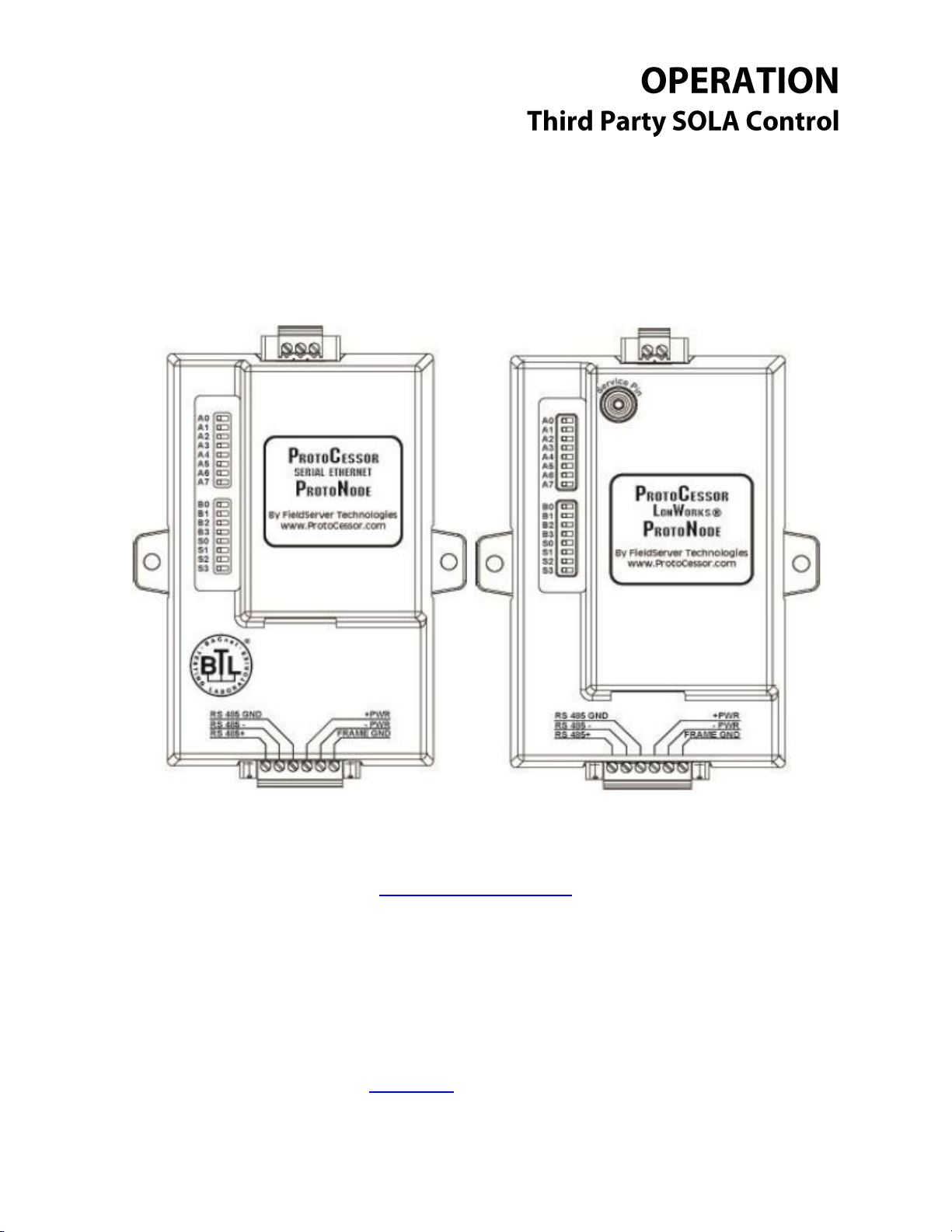
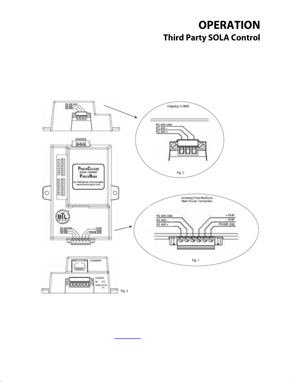
BACnet UDP IP / MSTP / Metasys N2 Module: General and Connection
Overview
The BACnet ProtoNode provides three access ports (one server side, one client side and a service
port/UDP IP port). The six pin connector (Fig. 1) provides RS 485 connection to the ModSync as well
as provides the 24vdc power to the ProtoNode itself. The three pin connector (Fig. 2) provides RS 485
_____________________________________________________________________________________
Questions? Call (315) 298-5121 or visit us online at www.fulton.com
©The Fulton Companies 2013
Supplement SOLA-IOM-2013-0220

__________________________________________________________
connection to the Building Management System. The last available port is the Ethernet port (Fig. 3),
which is used for service situations such as downloading configuration files.
The bank of dipswitches (see top view), are used to configure the ProtoNode in the field. Available
configurations are node address, baud rate and configurations profile. See Node Address Setup
And Baud Rate Settings for more details.
Return to Table of Contents
_____________________________________________________________________________________
Questions? Call (315) 298-5121 or visit us online at www.fulton.com
©The Fulton Companies 2013
Supplement SOLA-IOM-2013-0220
__________________________________________________________
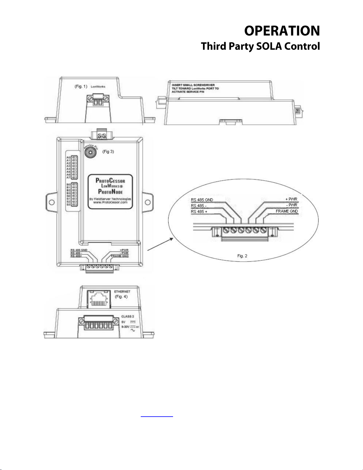
Lonworks Module: General and Connection Overview
The Lonworks ProtoNode provides three access ports (one server side, one client side and a service
port). The six pin connector (Fig. 2) provides RS 485 connection to the ModSync as well as provides the
24vdc power to the ProtoNode itself. The two pin connector (Fig. 1) provides Lonworks connection to
the Building Management System. The last available port is the Ethernet port (Fig. 4), which is used for
service situations such as downloading configuration files.
_____________________________________________________________________________________
Questions? Call (315) 298-5121 or visit us online at www.fulton.com
©The Fulton Companies 2013
Supplement SOLA-IOM-2013-0220
__________________________________________________________
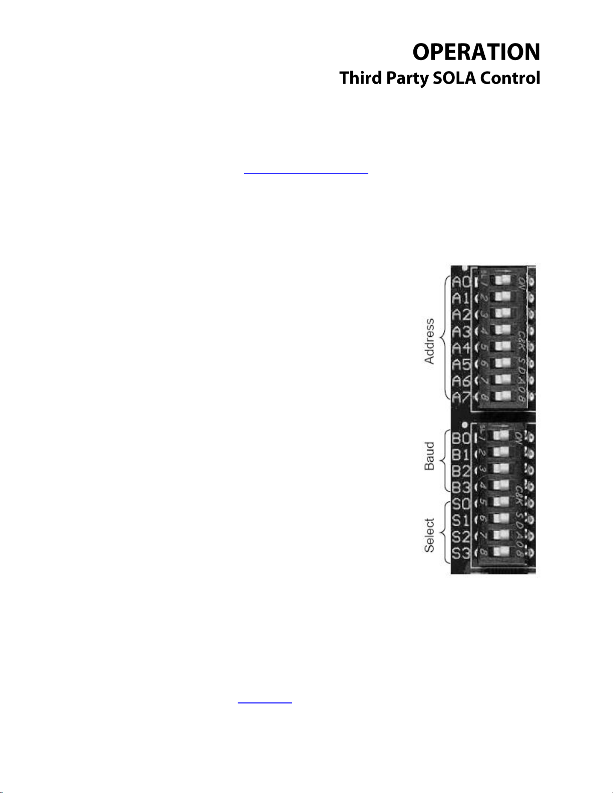
Dipswitches A0 – A7 are used to set the node
address of the ProtoNode device. See Addendum 1
for full address list and settings.
Dipswitches B0 – B3 are used to set the ProtoNode
baud rate. See Addendum 2 for full list and settings.
Dipswitches S0 – S3 are used to set which profile the
ProtoNode uses when it loads the config files it
requires to function. See Addendum 3 for full profile
list and settings.
The bank of dipswitches (see top view), are used to configure the ProtoNode in the field. Available
configurations are node address, baud rate and configurations profile.
Return to Table of Contents
Module Dipswitch Overview: All Modules
_____________________________________________________________________________________
Questions? Call (315) 298-5121 or visit us online at www.fulton.com
©The Fulton Companies 2013
Supplement SOLA-IOM-2013-0220
__________________________________________________________
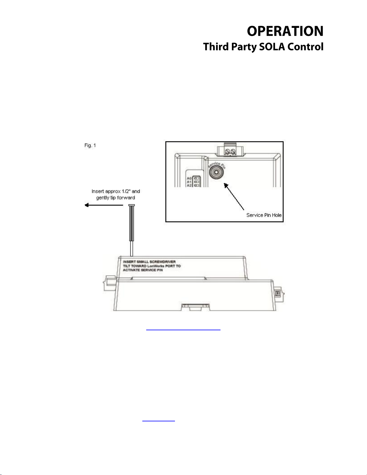
Module Service Pin: Lonworks Module Only
The service pin is used during the commissioning process on a Lonworks network. In order to use the
service pin on this module you will need a small screwdriver, small enough to fit into the service pin
hole. Put the screwdriver into the service pin hole and tilt gently forward towards the Lonworks 2 pin
connector. See Fig. 1.
Return to Table of Contents
_____________________________________________________________________________________
Questions? Call (315) 298-5121 or visit us online at www.fulton.com
©The Fulton Companies 2013
Supplement SOLA-IOM-2013-0220

__________________________________________________________
Downloading New Configuration Files: All Modules
The ProtoNode modules come with all the standard configuration files already installed for use.
However, under certain circumstances configuration files may have to be updated in the field. Use
the following steps to update the configuration files for a module already in service in the field. The
steps are the same for all modules with the slight exception to the Lonworks module; see the
exceptions note at the end.
1. Once you have gone through all the proper channels to get the point mapping completed, you
will receive a ZIP file that contains several files. While the total amount of files in the ZIP will vary,
two files will remain constant:
a. Ruinet.exe
b. Profile.bat
These files can be run from any folder on your computer, so long as all files in the ZIP stay
together in the same folder. In most cases it is advantageous to extract the files to a single
folder on your desktop or another easy to locate place for easy access.
* Example folder containing the new configuration files.
_____________________________________________________________________________________
Questions? Call (315) 298-5121 or visit us online at www.fulton.com
©The Fulton Companies 2013
Supplement SOLA-IOM-2013-0220
 Loading...