


FB-S
Fulton Steam
Horizontal Boiler
FB-S Series
100-800 Hp
Installation, Operation and Maintenance Manual
Serial # __________________________
Model # __________________________
Fulton Order # __________________________
Sold To __________________________
Job Name __________________________
Date __________________________
The Fulton Companies
972 Centerville Road
Pulaski, NY 13142
Telephone: (315) 298-5121
Facsimile: (315) 298-6390
www.fulton.com
The Fulton Companies*FB-S Series Manual*Version 2010-0820 rev. 3/5/13
Page 1

The Fulton Companies*FB-S Series Manual*Version 2010-0820 rev. 3/5/13
Page 2

Table of Contents
Introduction
Section 1 – Safety Warnings &
13. Boil-out of new unit
Section 4 – Controls & Burner
Precautions
Section 2 – Description &
Introductions
1. General
2. Specifications & Dimensions
Section 3 – Installation
1. Locating the boiler
2. Boiler room ventilation
3. Flue & chimney requirements
4. Recommended Water Conditions
5. Water Supply
6. Glossary of Water Terms
7. Valves
8. Electrical requirements
9. Gas supply
10. Oil supply
11. Installation check points
12. Cleaning
1. Boiler control panel
2. Burner
Section 5 – Operation
1. Fitting the boiler
2. Starting the burner
3. Daily operating test
4. Blowdown procedure
5. To shutdown the burner
6. Evaporation test
7. Fault finding
Section 6 – Maintenance
1. General
2. Weekly
3. Six monthly
4. Annually
5. Fitting new gasket
Section 7 - Warranty
The Fulton Companies*FB-S Series Manual*Version 2010-0820 rev. 3/5/13
Page 3

The Fulton Companies*FB-S Series Manual*Version 2010-0820 rev. 3/5/13
Page 4

Introduction
This operating manual presents information that will help to properly operate and care for the equipment.
Study its contents carefully. The unit will provide good service and continued operation if proper operating
and maintenance instructions are followed. No attempt should be made to operate the unit until the
principles of operation and all of the components are thoroughly understood. Failure to follow all
applicable instructions and warnings may result in severe personal injury or death.
These instructions must not be considered as a complete code of practice, nor should they replace
existing codes or standards which may be applicable.
The requirements and instructions contained in this section generally relate to the Fulton model FBS.
When installing a packaged unit, this entire section should be read to ensure that the installation work is
carried out correctly.
Prior to shipment, the following tests are made to assure the customer the highest standards of
manufacturing.
a) Material inspections
b) Manufacturing process inspections
c) ASME welding inspection
d) ASME hydrostatic test inspection
e) Electrical components inspection
f) Operating test
g) Final engineering inspection
h) Crating inspection
Note
The installation of the boiler should be carried out by competent personnel in accordance with the
standards of the National Fire Protection Association. All state and jurisdictional codes beyond
the scope of the applicable ASME boiler and pressure vessel codes, for its corresponding
classification, should be followed in all cases. Jurisdictional authorities must be consulted prior
to installation.
The Fulton Companies*FB-S Series Manual*Version 2010-0820 rev. 3/5/13
Page 5
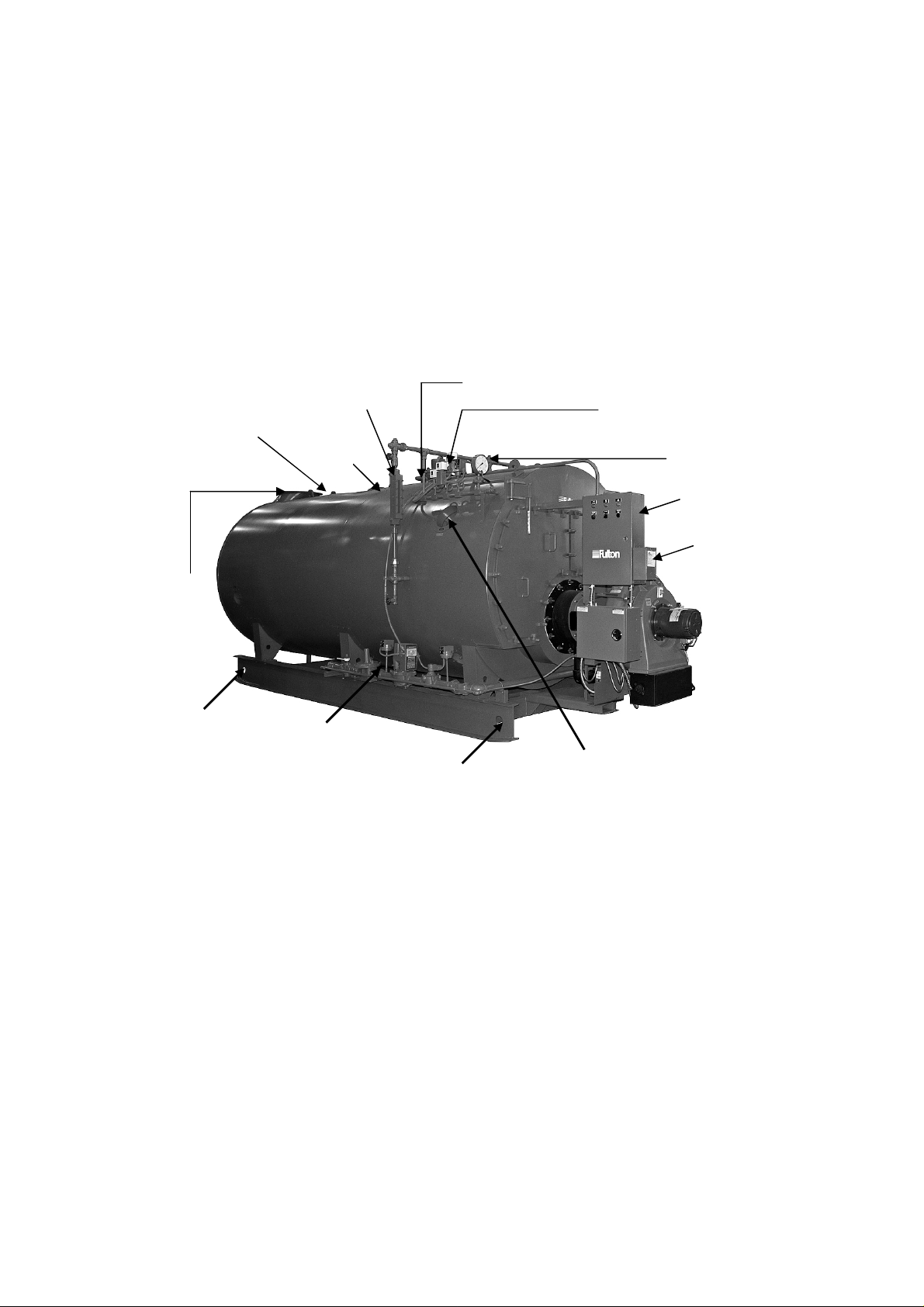
All units are crated for crane lift transport. Under no circumstances should weight be allowed to bear on
Gas Train
the jacket, control panel, or fan housing of the boiler.
The customer should examine the boiler for any damage, especially the refractories around the burner.
Rigging your boiler into position should be handled by a competent rigger experienced in handling heavy
equipment.
Safety Valve
Connection
Stack Connection
Sight Glass
Manway
Steam Outlet
Pressure Controls
Pressure Gauge
Control Panel
Burner
Rigging Point
(each side)
*Lifting eyes on top
may be used also*
Rigging Point
(each side)
*Lifting eyes on top
may be used also*
ASME Stamping
The Fulton Companies*FB-S Series Manual*Version 2010-0820 rev. 3/5/13
Page 6

Section 1
The Fulton Companies*FB-S Series Manual*Version 2010-0820 rev. 3/5/13
Page 7

The Fulton Companies*FB-S Series Manual*Version 2010-0820 rev. 3/5/13
Page 8

Section 1 – Safety Warnings & Precautions
The following WARNINGS, CAUTIONS and NOTES appear in various chapters of this manual.
They are repeated on these safety summary pages as an example and for emphasis.
• WARNINGS must be observed to prevent serious injury or death to personnel.
• CAUTIONS must be observed to prevent damage or destruction of equipment or loss of
operating effectiveness.
• NOTES must be observed for essential and effective operating procedures, conditions,
and as a statement to be highlighted.
WARNING
Do not operate, service or repair this equipment unless you fully understand all applicable
sections of this manual.
Prior to commencing any internal work on any control panel or electrical junction box, the
power must be disconnected.
Do not allow others to operate, service or repair this equipment unless they fully
understand all application sections of this manual, and are qualified to operate/maintain
the equipment.
Gauge glass valves need to be fully open during boiler operation to prevent boiler water
damage in case of gauge glass failure.
Never tamper with low water cutoff sensors or circuitry.
Boiler blowdown water must be cooled to <140oF prior to discharge to a drain. Failure to
use an approved blow off vessel with adequate cooling could cause personnel/equipment
damage.
A warm boiler will have very hot metal exposed. Care should be taken not to touch these
open across without protective clothing.
The Fulton Companies*FB-S Series Manual*Version 2010-0820 rev. 3/5/13
Page 9

CAUTIONS
A temperature exceeding 100o F in the boiler room may cause premature failure of
electrical components on the boiler control panel.
The water chemistry in the boiler must be kept within limits outlined in this manual. Failure
to do so will likely cause premature boiler pressure vessel failure and poor steam quality.
Boiler feed water temperature must be 140o F or greater to prevent corrosion fatigue
cracking at the feed water nozzle.
The bolts that connect the boiler shell to the rails need to be loosened slightly before the
boiler is warmed up to allow thermal expansion of the pressure vessel. Failure to do so
will create unwanted pressure vessel stress.
NOTES
After installation is complete and prior to operation the pressure vessel should be cleaned
or boiled out per instructions included in this manual.
The normal water level is approximately the center of the water gauge glass.
To ensure that your Fulton Steam Boiler is kept operating safely and efficiently, follow the
maintenance procedures set forth in this manual.
It is normal for the boiler safety relief valve to weep water if the boiler is operated above
90% of the valve setpoint (i.e. weep will occur for a 100 psig valve if boiler is >90 psig).
To ensure the continued safety and efficiency of the boiler, the schedule of maintenance
outlined in this section should be adhered to.
The boiler blow off operation should be done a minimum of once during the day when the
boiler is at 10 PSIG or less.
After a new Fulton Boiler has been in operation for several months, pieces of burned metal
will be found in the space at the bottom of the boiler. These pieces of metal are the
remains of a light gauge metal form which was used during manufacture for forming the
The Fulton Companies*FB-S Series Manual*Version 2010-0820 rev. 3/5/13
Page 10

boiler insulation. This is a normal condition and does not affect the efficiency or the life of
the boiler in any way.
All secondary low water trips, flame failure trips or high steam pressure trips will require,
by code, a manual reset at the boiler.
The Fulton Companies*FB-S Series Manual*Version 2010-0820 rev. 3/5/13
Page 11

The Fulton Companies*FB-S Series Manual*Version 2010-0820 rev. 3/5/13
Page 12

Section 2
The Fulton Companies*FB-S Series Manual*Version 2010-0820 rev. 3/5/13
Page 13

The Fulton Companies*FB-S Series Manual*Version 2010-0820 rev. 3/5/13
Page 14

Section 2 – Description & Introductions
1. General
a) Fulton model FB-S is a three-pass, water back and corrugated furnace design
steam boiler. In the first pass, the flame and high temperature flue gas flows from
the front to the back of the furnace. Through the second pass pipes, high
temperature flue gas flows from the combustion furnace to the front chamber. In
the third pass, the flue gas passes through the third pass pipes to the back of the
boiler and vents out. Corrugated furnace highly increases the heat exchange
area, heat transfer efficiency and reduces the possible damage to the boiler
durability cased by heat expansion and cold contraction.
b) Boiler is designed and manufactured to comply with ASME Code, with maximum
working pressure of 1.0MPa (150 PSI).
c) The fully packaged boiler has passed the strict test before it is delivered to the
customer. The equipment will give long life and excellent service on the job if
proper operating and maintenance instructions are followed.
d) FB-S boiler is a cylindrical vessel, with horizontal tubes passing through and
connected to the front and rear tube sheets. The vessel contains the water and
absorbs the energy generated from the flame. The front door and rear door
provide the seal to contain the hot combustion gasses. Baffles designed into the
doors serve to redirect the combustion gasses through the various firetube
passages. The flame originates in the furnace. As the combustion gasses travel
down the furnace and through the various firetube channels, heat from the flame
and combustion gasses is transferred to the water. Transferred energy develops
into the required steam or hot water.
e) The front door and rear door make it easy to clean the combustion chamber. The
pressure vessel can be inspected and repaired by the manhole on the top and
handholes on the side or bottom. The general information in this manual applies
directly to boilers in sizes ranging from 1 ton/hr through 6 ton/hr steam output
boiler for the following fuels: gas, No.2-6 Oil, No2 Oil and Gas.
f) The boiler is equipped with an automatic burner for fully modulating output.
The Fulton Companies*FB-S Series Manual*Version 2010-0820 rev. 3/5/13
Page 15
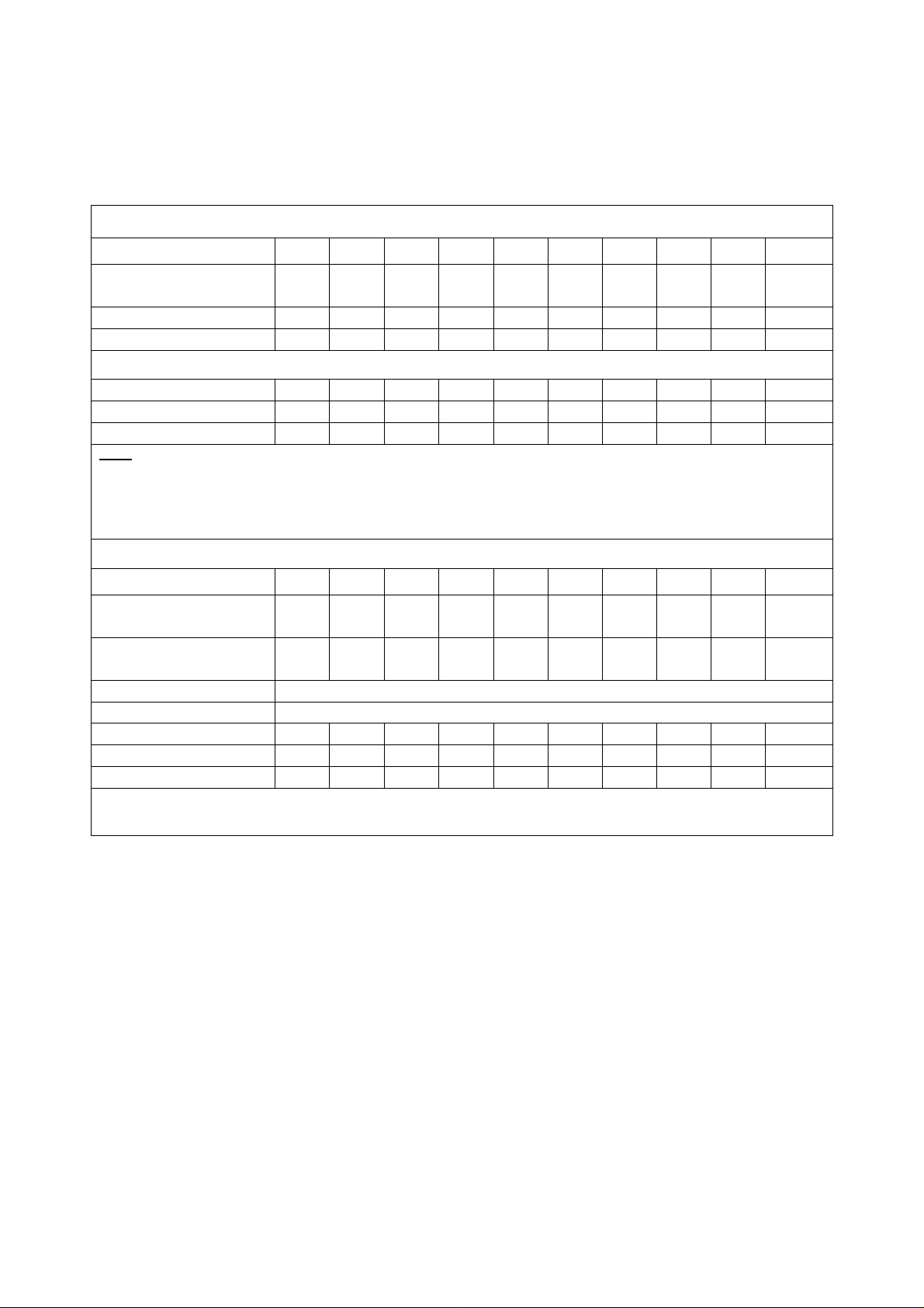
2. Specifications and Dimensions
Specifications
Model FB
-S
Maximum fuel consumption
Connection
Model FB
-S
100 125 150 200 250 300 400 500 650 800
100 125 150 200 250 300 400 500 650 800
Nominal steam output
(lbs/h) (1)
Design pressure (psig) 15/150
Water Volume (gallons) 779
Light Oil (gp/h) 29 36 43 58 73 88 117 146 189 234
Heavy Oil (gp/h) 27 34 41 54 68 82 108 136 177 216
Natural Gas (ft3/h) 4156 5196 6235 8313 10,392 12,470 16,626 20,784 27,019 33,252
Note:
(1) All steam output lbs/hr ratings from 0 psig at 212F.
(2) Fuel consumption based on light oil 1, 40,000 BTU/gal, natural gas 1000 BTU/ft3, heavy oil 160,000
BTU/gal.
3450 4312 5175 6900 8625 10350 13800 17250 22425 27600
15/150 15/150 15/150 15/150 15/150 15/150 15/150 15/150 15/150
924 924 1294 1585 1849 3594 4650 4677 5265
(2)
Main steam valve (150 psig)
Flange
Safety valve connections
(150 psig) (in)
Main steam valve (15 psig) (in) Consult Factory
Safety valve (15 psig) (in) Consult Factory
Feed Water inlet line (in) 1.0 1.25 1.25 1.25 1.25 1.5 1.5 2 2 2
Blowdown line (in) 1.5 (2) 1.5 (2) 1.5 (2) 1.5 (2) 1.5 (2) 1.5 (2) 1.5 (2) 2 (2) 2 (2) 2 (2)
Flue diameter (in) 14 16 16 18 20 20 22 22 26 26
2.5 3 3 4 4 4 6 6 6 8
2 1.5 (2) 1.5 (2) 2 (2) 2 (2) 2.5 (2) 2.5 (2) 4 4 (2) 4 (2)
Note: Specifications and dimensions are approximate. Fulton reserves the right to change specifications and
dimensions.
The Fulton Companies*FB-S Series Manual*Version 2010-0820 rev. 3/5/13
Page 16

Section 3
The Fulton Companies*FB-S Series Manual*Version 2010-0820 rev. 3/5/13
Page 17

The Fulton Companies*FB-S Series Manual*Version 2010-0820 rev. 3/5/13
Page 18
Section 3 – Installation
General
Note
It is essential that the installing shall be undertaken only by suitably qualified and
experienced personnel. Installation should comply with appropriate local and state codes
and standards.
1. Locating the Boiler
a) The boiler should be closed in dry surroundings on a level base, making sure that
there is sufficient room around the boiler to enable the operator and/or the
maintenance engineer to gain access to all parts of the boiler. Check location for
ease of water supply and electrical connections.
b) Place the boiler on a non-combustible floor with clearances to unprotected
combustible materials, including plaster or combustible supports.
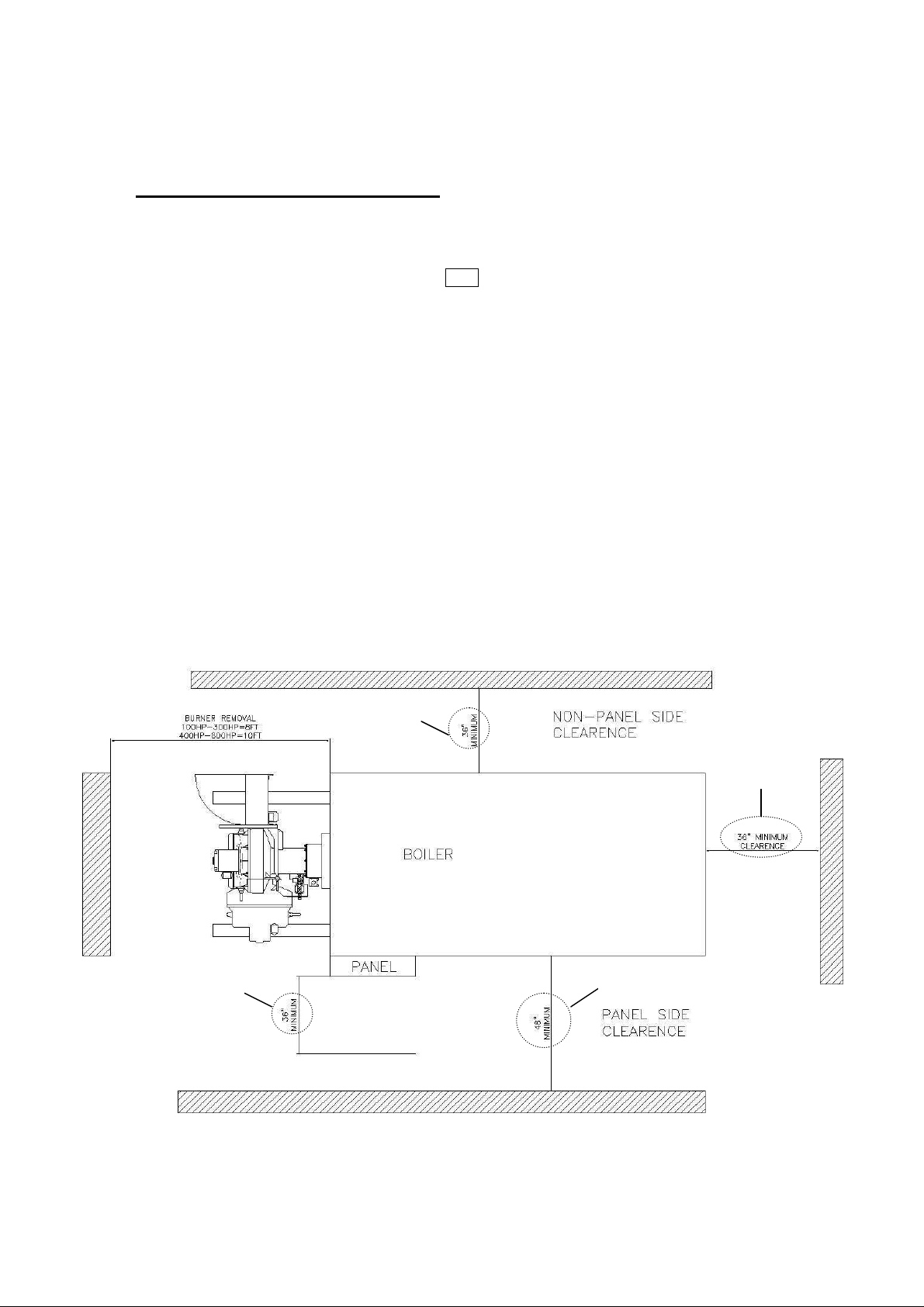
c) It is necessary to have enough clearance from the floor to the ceiling for
removing of the burner and have the following clearance from boiler for servicing:
36” Min
36” Min
Clearance
36” Min
48” Min
The Fulton Companies*FB-S Series Manual*Version 2010-0820 rev. 3/5/13
Page 19

2. Boiler Room Ventilation
Model FB
-S
100 125 150 200 250 300 400 500 650 800 900
a) It is most important to provide free access of air to the boiler. To burn fuel
properly, it requires one square inch opening of fresh air for every 3, 000 BTU
input of fuel.
b) Proper ventilation of the boiler room is essential for good combustion. Install two
make up air openings, one at a low level (24” or 610mm from floor) and one at a
higher level in the boiler room wall. This will provide a flow of air to exhaust the
hot air from the boiler room.
c) The following openings are recommended for each size boiler:
Recommended Minimum Makeup Air Openings
Minimum area (in2) 1437 1797 2156 2875 3593 4312 5750 7187 9343 11,500
d) Be sure the total BHP= proper make up air opening size. For instance, if you
have three 300 BHP boilers, it is a total BHP of 900, and the 900 BHP make up
air size is recommended.
These measurements are subject to state and local regulations. The
installation of exhaust fans in a boiler room is not recommended. An
exhaust fan can create down draft in the stack or restrict the burner’s air
supply which will result in poor combustion. It is essential that only fresh
air be allowed to enter the combustion air system. Foreign substances,
such as combustible volatiles and lint, in the combustion system can
create hazardous conditions.
3. Flue and Chimney Requirements
a) The flue from the appliance and the joint between this flue and the chimney are
sealed to prevent leakage of combustion products.
b) The top of the flue or chimney shall be higher than any roof within a radius of 10
meters.
c) Checks are made to ensure that the chimney is suitable for burner and that the
proposed installation complies with the local authority and other regulations
covering such installations.
Note
The Fulton Companies*FB-S Series Manual*Version 2010-0820 rev. 3/5/13
Page 20

d) If more than one appliance is connected to a common flue or chimney the cross-
Carbon Steel
Parameter
Feedwater
Horizontal Boiler/SteamPac Wa
ter
pH
Feedwater
Hardness as
CaCO3
Chlorides
Total Alkalinity
Total Dissolved
Suspended
Total Orga
nic
Iron
Dissolved
Visual Oil
Conductivity
section of the chimney should be adequate for the total volume of combustion
products from the appliances.
e) The total horizontal run of the boiler flue should not exceed 25% of the total
vertical rise. There should be an angle more than 15 degrees for the horizontal
run reducing the resistance of the combustion products and avoid rusting by
accumulating condensation in the flue.
f) The installer should check the draft with a meter at 0 to 0.15” W.C pressure with
the burner off. If the pressure is too low, a balancing damper may be used close
to the flue outlet to regulating the pressure of the draft.
4. Recommended Water Conditions
a) Following are recommendations for feed water and boiler water. Contact your
local water treatment professional for testing and treatment recommendations. It
is very important that a strict water treatment program be followed.
b) It is critical that the boiler pH water chemistry follow the attached schedule
whenever water is in the boiler. Solids that enter in with the feed water will
concentrate in the boiler. A regular schedule of boiler blowdown must be
maintained to prevent high solid concentrations from corroding the vessel or
forming deposits
7.5-9.5 8.5-10.5
140F* ---
Temperature
< 2ppm < 15 ppm
--- ---
--- < 500 ppm
--- < 3000 ppm
Solids
No visual turbidity** No visual turbidity**
Solids
No sheen No foam + No sheen No foam +
Carbon
Colorless liquid++ Colorless liquid++
<1 ppm* ND
Oxygen
ND ND
--- < 4477
(µµµµS/cm)
NOTES:
*Feedwater temperatures below 200oF will require an oxygen scavenger
** Suspended solids: Take a water sample. After the sample sits for 10 minutes, no solids should be visible.
The Fulton Companies*FB-S Series Manual*Version 2010-0820 rev. 3/5/13
Page 21

+ Total Organic Carbon: Take a water sample. Shake vigorously for 30 seconds. No sheen or foam should be visible.
++ Iron: Take a water sample. Hold the sample against a white background. The water should have no visible yellow, red
or orange tinge.
ND: None Detected.
5. Water Supply
a) The quality of the water used in the boiler will affect the life of the elements and
pressure vessel and it is strongly recommended that a competent water
treatment company be consulted prior to the installation of the boiler. PV
damaged due to adverse water conditions will not be replaced under warranty.
b) Natural feedwater supplies contain solids and dissolved gases. These may
promote scale, foaming, corrosion, and/or poor steam quality. To prevent this,
feedwater must be studied individually and treated accordingly. The treatment
should provide quality feedwater to the boiler such that corrosion and deposition
in the boiler will be minimized. Thermal cycling, dissolved oxygen, high or low pH
can all be major causes of corrosion. Untreated hardness is the major cause of
scale deposits. Poor quality feedwater requires increased blowdown and
increased chemical treatment costs to prevent boiler corrosion and scaling.
c) One way to lower the amount of dissolved gases in the boiler feed water is to
preheat the feedwater. This option injects live steam into the feedwater to
increase the water temperature to 180 degrees F or higher which removes
oxygen and carbon dioxide from the water.
d) RO/DIWater: Reverse Osmosis / Deionized water is water that all dissolved
solids have been removed. Very high purity steam quality can be obtained with
RO/DI water. RO/DI water has no buffering capacity and a pH of <6.5. It is
corrosive to carbon steel, however, not to stainless steel. Therefore, anytime
RO/DI water is used in a carbon steel vessel, pH neutralization is required to
bring the pH up to the required level.
e) The Fulton Warranty does not cover damage or failure that can be attributed to
corrosion, scale or fouling.
6. Glossary of Water Supply Terms
a) Dissolved Oxygen: Oxygen that is dissolved in the feedwater will cause the
steel in the boiler and the feedwater system to be attacked by the water in a
manner described as “pitting”. The pits that are produced can vary from tiny
depressions to holes large enough to penetrate the boiler metal and are usually
covered with tubercles of iron oxide. Once pitting starts, it may be extremely
hard to arrest. Pitting can proceed at a surprisingly rapid rate and can occur not
The Fulton Companies*FB-S Series Manual*Version 2010-0820 rev. 3/5/13
Page 22

only in the boiler proper, but also in pre-boiler equipment such as ecomomizers,
feedwater tanks, and feedwater lines.
b) Sodium Sulfite: Its purpose is to chemically remove the dissolved oxygen left in
the feedwater after the feedwater has been mechanically deareated. Sodium
Sulfite reacts chemically with dissolved oxygen, producing sodium sulfate. Since
it is desirable to remove dissolved oxygen from the feedwater before it reaches a
boiler. Sodium sulfite is best introduced continuously at some suitable point in the
feedwater system (the storage section of the feedwater heater or deareator, six
inches below the water line). Chemical residual control is based on the
maintenance of a specific excess of sodium sulfite in the boiler water. The
essential requirement being to maintain in the feedwater at all times slightly more
than enough sodium sulfite to consume all of the dissolved oxygen that slips
through the deareating equipment. Sulfite as a treatment represents the second
line of defense against oxygen corrosion. Primary protection against this type of
attack requires adequate facilities for mechanical deareation of the feed-water
plus a vigorous maintenance program to safe guard against oxygen leakage into
the pre-boiler system.
c) Suspended Solids: Suspended solids are the undissolved matter in water, inc-
luding dirt, silt, vegetation, iron oxides, and any other insoluble matter. Normally
suspended solids are expressed in terms of turbidity. Suspended solids may also
deposit in low velocity areas and create fouling. In line filters, or various types of
pretreatment can be used to lower the suspended solids level. Various polymers
assist in holding solids in suspension. Periodic blowdowns will eliminate
suspended solids.
d) Alkalinity: Alkalinity is the capacity of a water to neutralize acids. Common water
alkalinities consist of bicarbonate, carbonates, hydroxide, phosphate, and
silicate. These alkalinities, especially bicarbonates and carbonates, break down
to form carbon dioxide in steam, which is a major factor in the corrosion on
condensate lines. High alkalinity also causes foaming and carry over in boilers.
Both foaming and carry over cause erratic boiler operation. When foaming occurs
an antifoam should be added or increased. The reason for the high alkalinity
should be determined. It may result from lack of sufficient blow off. Quite often
the source of alkalinity is an overdose of alkaline internal water treatment
chemical.
e) pH: pH is a measure of the degree of acid or base of solution. pH ranges of 8.0-
10.5 will have little influence on the corrosion rate of carbon steel. A low pH can
result in corrosion of metals, while a high pH can result in scale formation or
The Fulton Companies*FB-S Series Manual*Version 2010-0820 rev. 3/5/13
Page 23
 Loading...