

Page 1

PRO-RANGE 30” - 36” ELECTRIC INDUCTION
INSTALLATION INSTRUCTIONS
INSTRUCTIONS D’INSTALLATION
INSTRUCCIONES PARA LA INSTALACIÓN
Page 2

Page 3
Pay attention to these symbols present in this manual:
EN
TABLE OF CONTENTS PAGE
1 - Special Warnings 2
Before Starting Installation 2
Mobile Home Installation 2
2 - Product Dimensions and Cutout Requirements 3
Anti-Tip Bracket Installation 5
3 - Installation Information 6
4 - Installation Instructions 7
5 - Electrical supply 9
6 - Electrical connections 11
4-wire connection 12
3-wire connection 12
Direct Electrical Connection to the Circuit Breaker,
Fuse Box or Junction Box 13
7 - Final checklist 14
DANGER
You can be killed or seriously injured if you don’t
IMMEDIATELY follow instructions.
WARNING
This is the safety alert symbol. This symbol alerts you to
potential hazards that can kill or hurt you and others. You
can be killed or seriously injured if you don’t follow these
instructions.
READ AND SAVE THESE INSTRUCTIONS.
To installer:
Leave these instructions with the appliance.
To customer:
Retain these instructions for future reference.
IMPORTANT: Save these instructions for the local electrical
inspector use.
INSTALLER: Please leave this manual with owner for future
reference.
OWNER: Please keep this manual for future reference.
WARNING
If the information in this manual is not followed exactly, a fire
or explosion may resulting in product and property damage
and / or personal injury or death.
Do not store or use gasoline or other flammable vapours and
liquids in the vicinity of this or any other appliance.
1
Page 4
EN
1 - Special Warnings
IMPORTANT INSTRUCTION
Special Warnings
Please read all instruction before using this appliance.
Proper installation is your responsibility. Have a qualified
technician install this range.
IMPORTANT
- Observe all governing codes and ordinances.
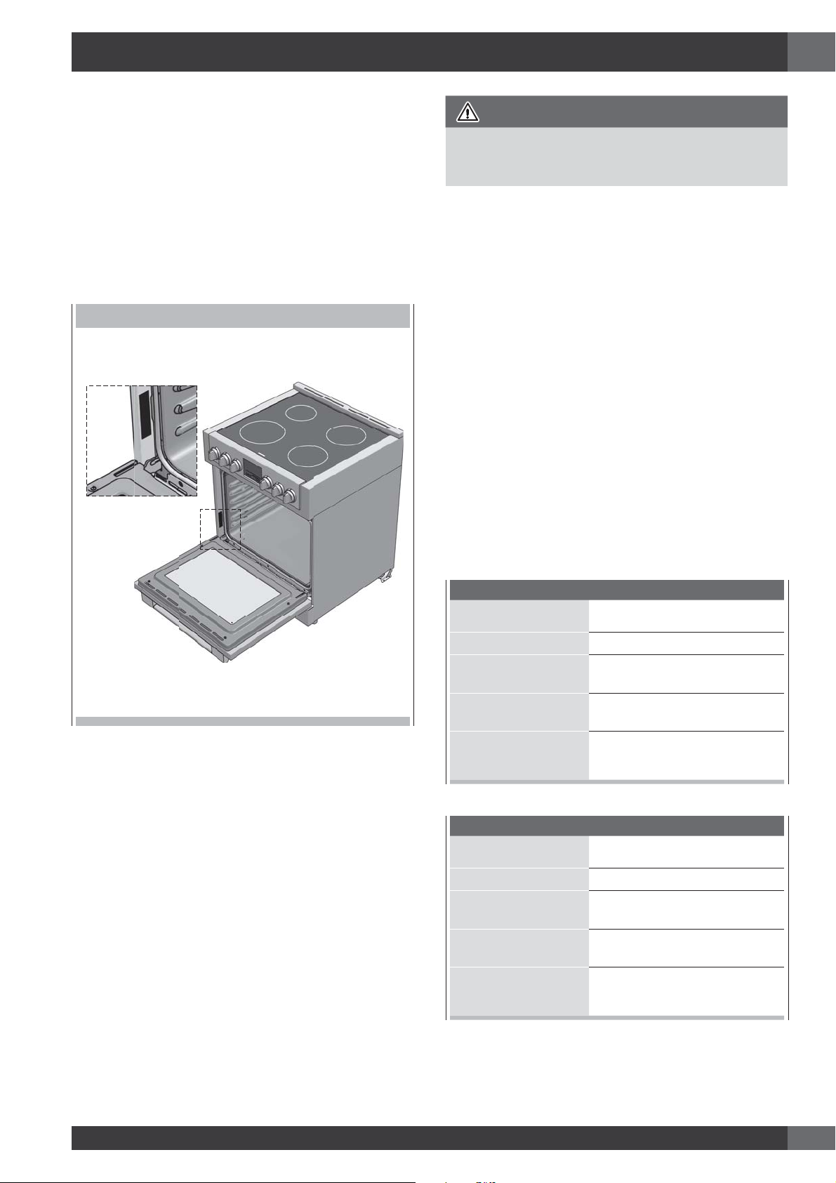
- Write down the model and serial numbers before installing
the range. Both numbers are on the serial rating plate refer
to the illustration below.
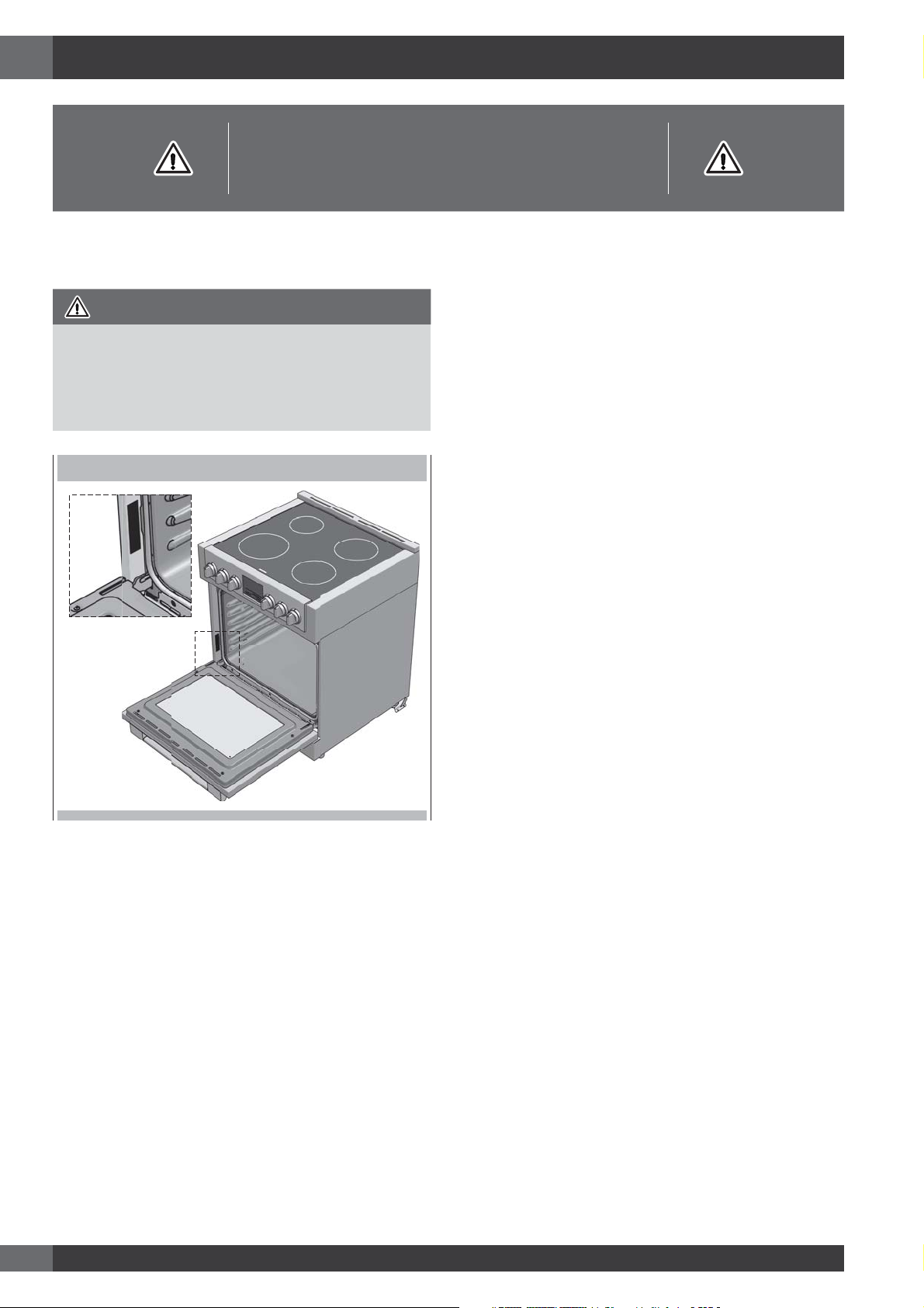
LOCATION OF RATING PLATE
Mobile Home Installation
The installation of this appliances must conform to the
Manufactured Home Construction and Safety Standards, Title
24 CFR, Part 3280 (formerly the Federal Standard for Mobile
Home Construction and Safety; Title 24 HUD part 280); or
when such standard is not applicable, the Standard for
Manufactured Home Installations (Manufactured Home Sites,
Communities and Setups), ANSI A225.1 - latest edition, or
with local codes.
In Canada, the installation of this appliances must conform
with the current standards CAN/CSA-Z240 - latest edition, or
with local codes.
Before Starting Installation
• Check location where range will be installed. The location
should be away from strong drafty areas, such as windows,
doors and strong heating vents or fans.
• Electrical grounding is required. See “Electrical
Requirements”
• Assure that electrical installation is adequate and in
conformance with National Electrical Code, ANSI/
NFPA 70 - latest edition**, or Canadian Electrical Code,
part 1 C22.1 (latest edition)*** and all local codes and
ordinances.
Copies of the standards listed may be obtained from:
** National Fire Protection Association One Batterymarch Park
Quincy, Massachusetts 02269
*** CSA International 8501 East Pleasant Valley Rd. Cleveland,
OH 44131-5575
2
Page 5
35
3/4
(9
1,0)
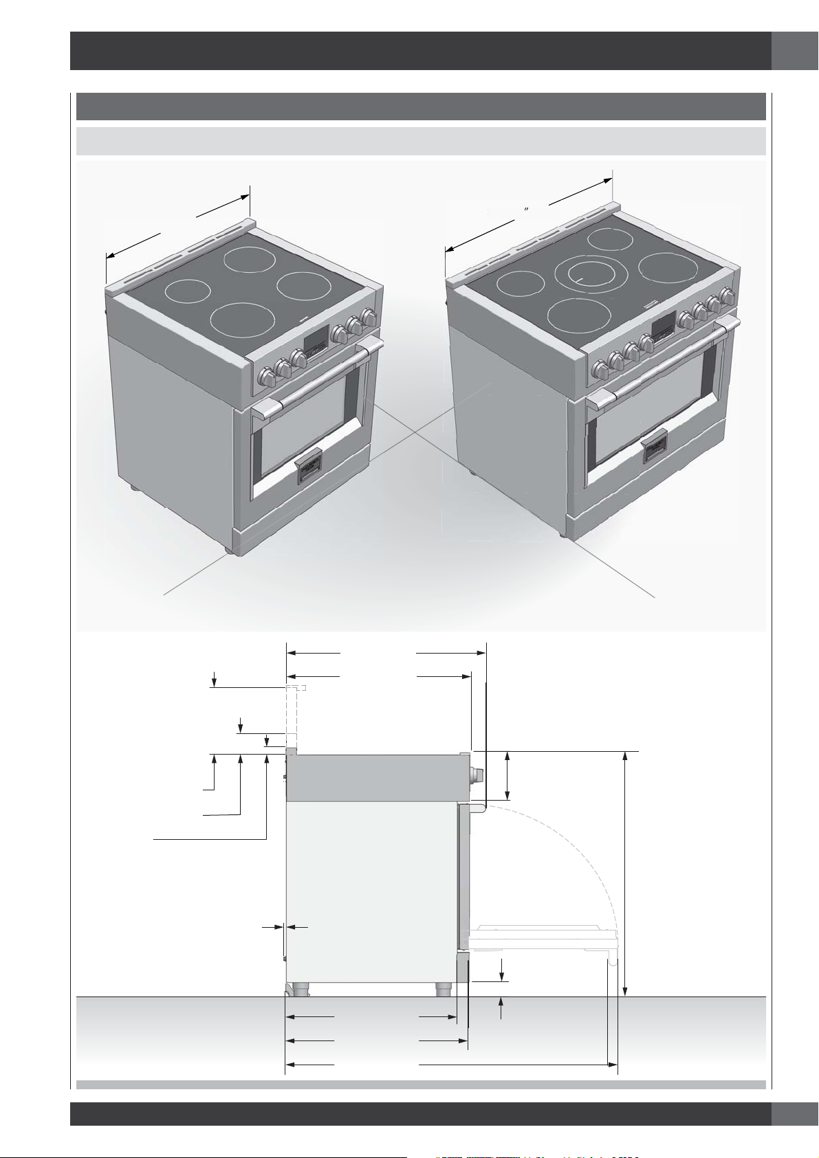
2 - Product Dimensions and Cutout Requirements
PRODUCT DIMENSIONS
30” Wide Range Models
EN
29 3/4” (75,8)
35 3/4” (91,0)
9" (22.8) [optional]
3" ( 7.6) [optional]
1" ( 2.5)
3/8” (1)
29 3/4” (75.6)
27 1/2” (69.7)
25 3/4” ( 65.4)
27 1/4” ( 69.1)
7 3/8” (18.7)
1 3/8” (3.5)
TO
3 3/8” (8.5)
Max. 37 1/4” (94.7)
Min. 35 3/8” (89.8)
47 3/4” (121.4)
3
Page 6
EN
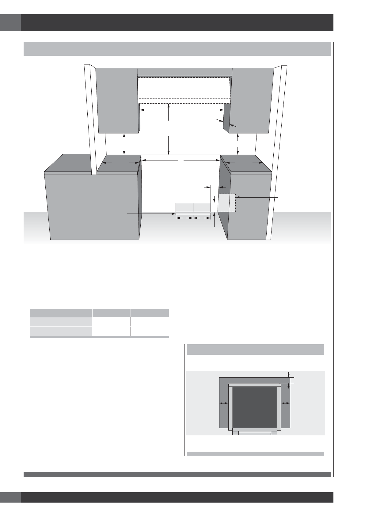
2 - Product Dimensions and Cutout Requirements
CUTOUT REQUIREMENTS
C
Max. 13” (33)
Min. 18” (45.7)
Min. 6”
(15.2)
*Suggested location
of utilities
Min. 18” (45.7)
Min. 6”
(15.2)
2” (5.1) max. protusion from
wall for gas or electrical supply
Min. 30” (76.2)
To bottom of
ventilation hood
A
3” (7.6)
ELECTRICGAS
B B
4” 3/4 (12.3)
The surface of the entire back wall above the range and below the hood must be covered with a noncombustible material.
*Consult local code for exact location requirements.
OPENING WIDTH A & C B
Range 30” 30" (76.2) 6” (15.2)
Range 36” 36" (91.4) 7” (17.8)
Note: Clearances to non-combustible materials must
conform with local codes or, in the absence of local
codes, with the National Fuel Gas Code, ANSI
Z223.1/NFPA 54.
Minimum clearances:
Above cooking surface (above 36” [91.4 cm])
• Sides 3” (7.6 cm)
• Within 3” (7.6 cm) side clearance, wall cabinets no
deeper than 13” (33.0 cm) must be minimum 18” (45.7
cm) above cooking surface.
• Wall cabinets directly above product must be a minimum
of 30” (76.2 cm) above cooking surface.
• Rear - 0” with 3” (7.6 cm) backguard.
ADDITIONAL CLEARANCES:
For island installation, maintain 2-½ in. minimum from
cutout to back edge of countertop and 3 in. minimum from
cutout to side edges of countertop (see top view).
FLUSH ISLAND TRIM INSTALLATION
BACK
min 2 1/2” (6.3)
min 3” (7.6) min 3” (7.6)
4
Page 7
2 - Product Dimensions and Cutout Requirements
EN
Before moving the range, protect any finished flooring and
secure oven door(s) closed to prevent damage.
Vent hood Combinations:
It is recommended that these ranges be installed in conjunction
with a suitable overhead vent hood.
Install a hood with at least 450 CFM.
Due to the high heat capacity of this unit, particular attention
should be paid to the hood and ductwork installation to assure
it meets local building codes.
WARNING
Clearances to horizontal surfaces above the range, measured
to the cooking surface are below. Failure to comply may
result in fire hazard.
• Installations without a hood require 30” (76) minimum to
combustibles.
• A custom hood installation with exposed horizontal
combustible surfaces must have an Auto-On feature.
• For other installations with a hood, refer to the hood
installation instructions for specific hood clearances.
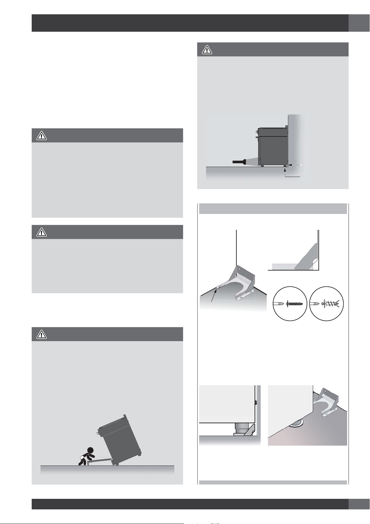
WARNING
To verify the anti-tip bracket is installed and engaged:
• Slide range forward.
• Look for the anti-tip bracket securely attached to floor or wall.
• Slide range back so rear range foot is under anti-tip bracket.
• See installation instructions for details.
Anti-Tip Bracket
Range Foot
ANTI-TIP BRACKET INSTALLATION
CAUTION
These ranges weigh up to 400 pounds. Some disassembly
will reduce the weight considerably. Due to the weight and
size of the range and to reduce the risk of personal injury or
damage to the product:
TWO PEOPLE ARE REQUIRED FOR PROPER INSTALLATION.
Anti-Tip Bracket Installation
WARNING
Tip Over Hazard
A child or adult can tip the range and be killed.
Ensure the anti-tip bracket is engaged when the range is
moved.
Do not operate range without anti-tip bracket installed and
engaged.
Failure to follow these instructions can result in death or serious
burns to children and adults.
WALL
ANCHOR
CABINET
SIDEWALL
FLUSH
BACKWALL
ANTI-TIP
BRACKET
For Concrete or Cement Construction:
You must use appropriate fastening hardware (not
provided).
Secure the bracket to the wall and/or floor with at least 4
wood screws (provided).
The anti-tip bracket should be inserted into the opening on
the anti-tip brace on the range.
5
Page 8
EN
3 - Installation Information
WARNING
• Excessive Weight Hazard
Use two or more people to move and install range.
Failure to do so can result in back or other injury.
• Cut Hazard
Beware of sharp edges. Use the polystyrene ends when
carrying the product. Failure to use caution could result in
minor injury or cuts.
Do not obstruct the flow air at the oven vent nor around the
base or beneath the lower front panel of the range. Avoid
touching the vent openings or nearby surfaces as they may
become hot while the oven is in operation.
CHOOSING RANGE LOCATION
Carefully select the location where the range will be placed.
The range should be located for convenient use in the kitchen,
but away from strong drafts.
Strong drafts may be caused by open doors or windows, or by
heating and/or air conditioning vents or fans.
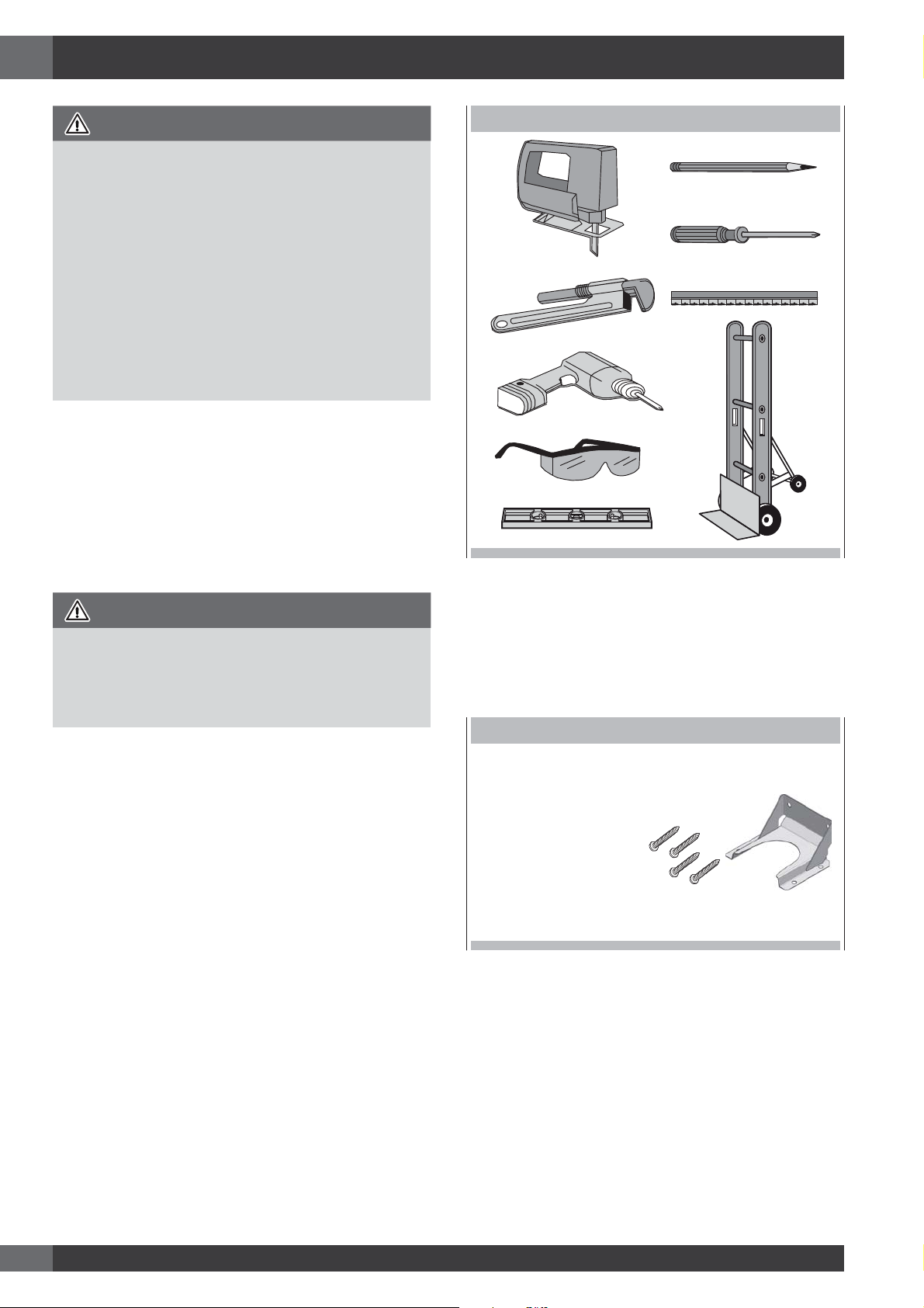
TOOLS WILL YOU NEED
IMPORTANT NOTE
When installing against a combustible surface, a minimum
riser is required for a the range, Follow all minimum
clearances to combustible surfaces shown in the illustration
on the previous pages.
Before moving the range, protect any finished flooring and
secure oven door(s) closed to prevent damage.
Do not lift or carry the range door by the door handle.
To eliminate the risk of burns or fire by reaching over heated
surface units, cabinet storage space located above the surface
units should be avoided. If cabinet storage is to be provided,
the risk can be reduced by installing a range hood that projects
horizontally a minimum of inches beyond the bottom of the
cabinets.
Remove packaging materials and literature package from the
cooktop before beginning installation.
Remove Installation Instructions from the literature pack and
read them carefully before you begin
MATERIALS PROVIDED
ANTI-TIP BRACKET
BRACE ABD SCREWS
6
Page 9
4 - Installation Instructions
EN
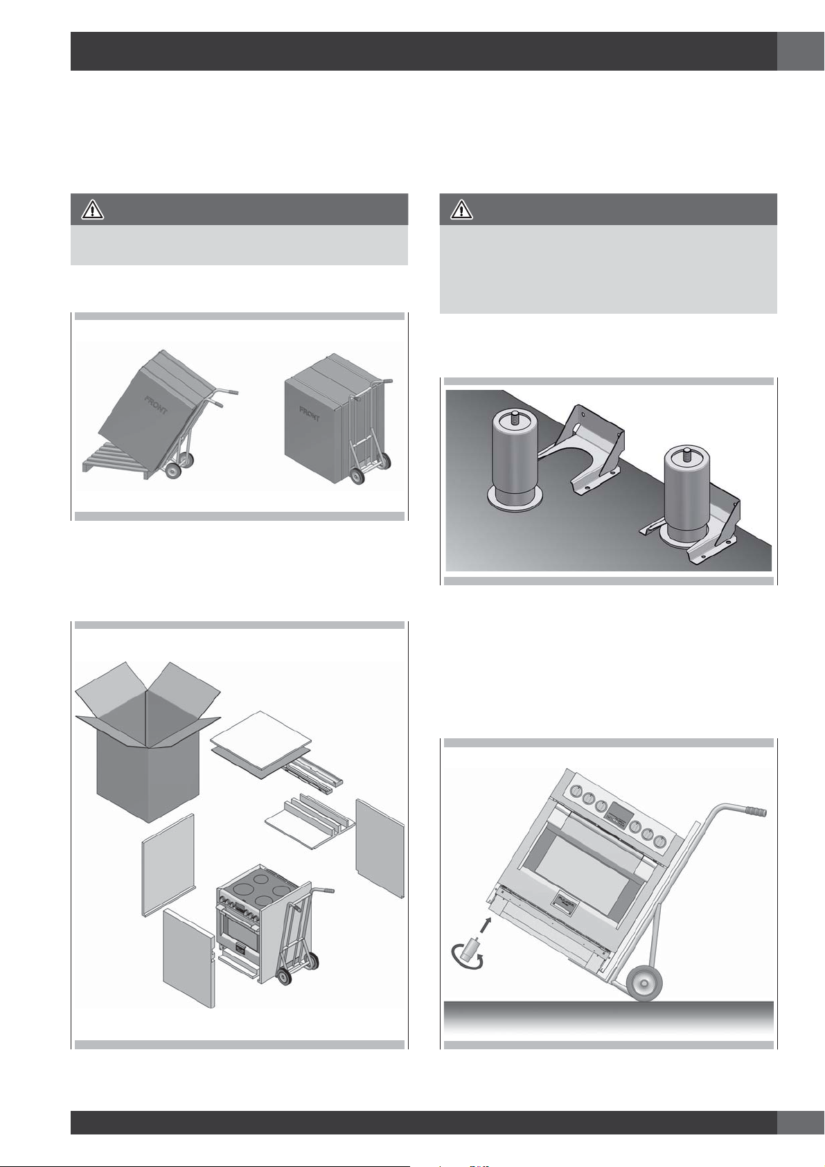
STEP 1
Cut the banding and remove the appliance from the pallet by a
hand-truck inserting the blade under the foam base.
CAUTION
Stand clear. The ends of the cut banding may snap toward you.
STEP 3
Move the range indoors before installing the legs, position the
appliance near its final location as the legs are not suitable for
moving the appliance over long distances.
Legs are packed in the cardboard top pack.
CAUTION
Doors and passageways leading to the installation location
require at least 31” opening. If the opening is less than 31”,
the oven door(s) and control knobs must be removed.
(see Use & Care manual for oven door removal instructions).
Note: the legs with collar must be mounted on the back of range
to engage the anti tip device.
STEP 2
Remove Installation Instructions from the top of range and read
them carefully before you begin.
STEP 4
With the foam base still in place, tilt the range laterally and
screw in the first pair of legs.
7
Page 10
EN
4 - Installation Instructions
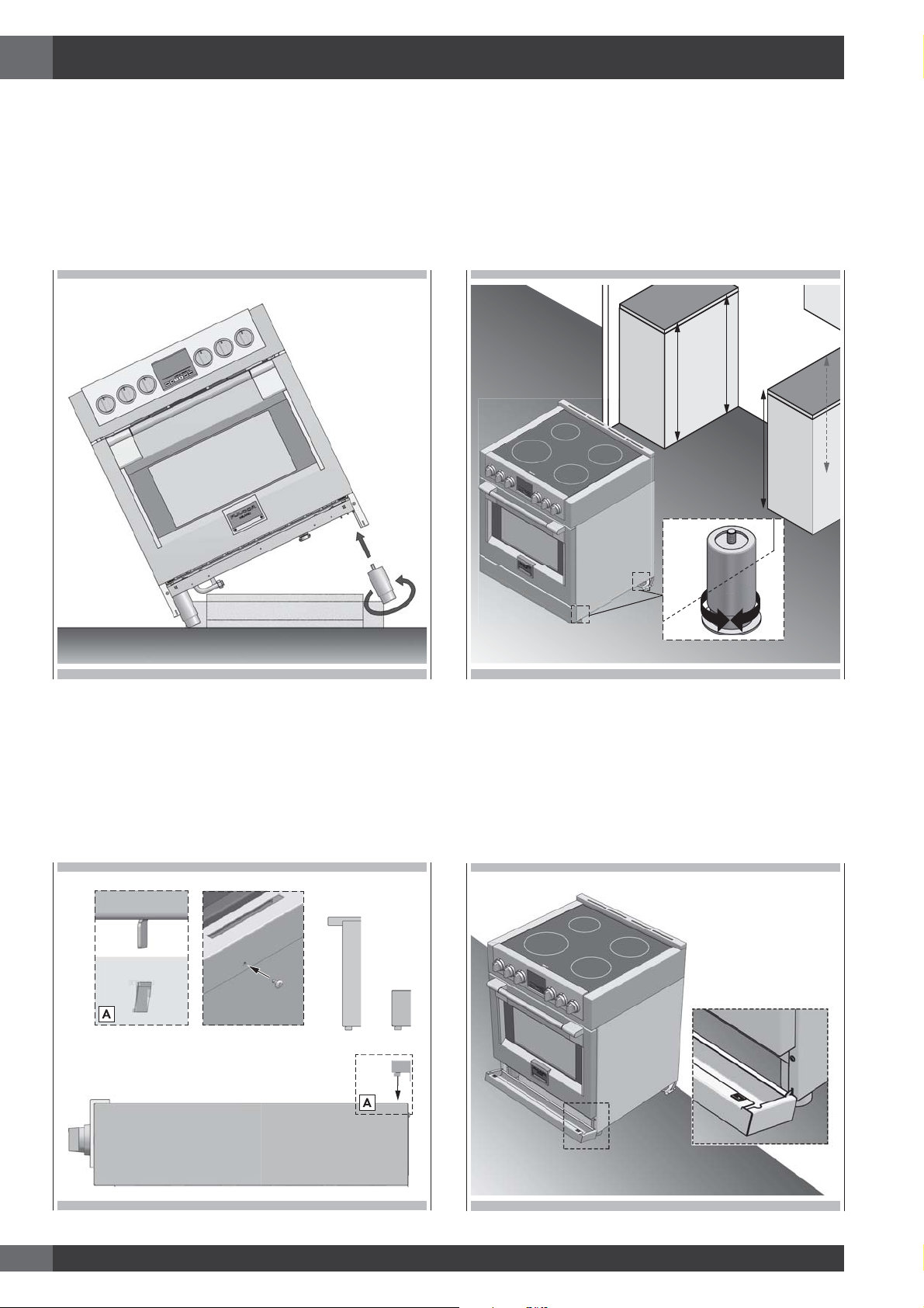
STEP 5
Pull out the hand-truck, tilt the range laterally and insert the
second pair of legs. Remove the base
STEP 7
After the electrical and gas connections (see both paragraphs
for instructions) measure the four corners in cutout area to verify
if flooring is level. Adjust the leveling legs to the desired height
and ensure range is level. Turn the bottom section of each leg
counter-clockwise to raise the leg and clock wise to lower it.
Ensure floor is protected. Slide unit into place making sure to
engage the anti-tip bracket.
STEP 6
Install the backsplash (if provided) by the three screws on the
back and the toe kick
3”9”
STEP 8
Hook tabs on bottom of toekick into slots on either side of
the frame and rotate up until clips at top of toekick engage
securely.
NOTE: Be sure the toekick snaps securely.
8
Page 11
5 - Electrical supply
EN
Before installing the oven have a qualified electrician verify
that your home is provided with adequate electrical service
and that the addition of the oven will not overload the
branch circuit on which it is to be installed.
Be sure your appliance is properly installed and grounded
by a qualified technician. Ask your dealer to recommend a
qualified technician or an authorized repair service.
This appliance is manufactured with a green GROUND
wire connected to the oven chassis Junction Box or Wall
Receptacle Location.
Suggested location of the junction box or wall receptacle is
showed in “Cutout requirements” Figure.
LOCATION OF RATING PLATE
WARNING
Risk of Electric Shock, frame grounded to neutral of
appliance through a link
Grounding through the neutral conductor is prohibited for
new branch-circuit installations (1996 NEC); mobile homes;
and recreational vehicles, or in an area where local codes
prohibit grounding through the neutral conductor. For
installations where grounding through the neutral conductor
is prohibited:
- Disconnect the ground from the neutral at free end of
conduit;
- Use grounding terminal or lead to ground unit; and
- Connect neutral terminal or lead to branch circuit neutral
in usual manner.
A 3-wire* or 4-wire single phase 120/240 or 120/208
Volt, 60 Hz AC only electrical supply is required on a
separate circuit fused on both sides of the line (time-delay
fuse or circuit breaker is recommended). DO NOT fuse
neutral.
Your local codes and ordinances, of course, take precedence
over these instructions. Complete electrical connections
according to local codes and ordinances.
A UL listed conduit connector must be provided at each end
of the power supply conduit (at the range and at the junction
box).
• Wire sizes and connections must conform with the rating
of the range.
In the United States:
Be sure that the electrical and grounding connections and
also wire size are adequate and in conformance with the
National
Electrical Code, ANSI/ NFPA 70-latest edition and all local
codes and ordinances.
NOTE: FOR USE WITH 208 V, 60 HZ SUPPLY VOLTAGE,
SEE CONNECTING TO 208 VOLT CIRCUIT.
ELECTRICAL REQUIREMENTS 30”
Electrical Supply 120-240V or 120-208V, 60 Hz
Service 50 amp dedicated circuit
Total Amps 120/240V 45.8 Amps
120/208V 48.5 Amps
Max Connected Load 120/240V 11.00 kW
120/208V 10.00 kW
Min Supply Wire L1, L2, ground 8 AWG
Neutral 10 AWG
ELECTRICAL REQUIREMENTS 36”
Electrical Supply 120-240V or 120-208V, 60 Hz
Service 50 amp dedicated circuit
Total Amps 120/240V 61.0 Amps
120/208V 63.0 Amps
Max Connected Load 120/240V 14.60 kW
120/208V 13.30 kW
Min Supply Wire L1, L2, ground 8 AWG
Neutral 10 AWG
In Canada:
Be sure that the electrical connection and wire size are
adequate and in conformance with CSA Standard C22.1,
Canadian Electrical Code, Part 1 - latest edition, and all
local codes and ordinances.
(*) Power limitation at 50.0 Amps
9
Page 12

EN
WARNING
ELECTRICAL SHOCK HAZARD
• The electrical power to the appliance branch circuit
must be shut off while line connections are being made.
• Do not use an extension cord with this appliance.
• Electrical ground is required on this appliance.
• The free end of the green wire (the ground wire) must
be connected to a suitable ground. This wire must
remain grounded to the appliance.
• If cold water pipe is interrupted by plastic, non metallic
gaskets, union connections or other insulating materials,
DO NOT use for grounding.
• DO NOT ground to a gas pipe.
• DO NOT have a fuse in the NEUTRAL or GROUNDING
circuit. A fuse in the NEUTRAL or GROUNDING circuit
could result in an electrical shock.
• Check with a qualified electrician if you are in doubt as
to whether the appliance is properly grounded.
• Failure to follow these instructions could result in serious
injury or death.
10
Page 13
6 - Electrical connections
EN
CAUTION
Do not repair or replace any part of the appliance unless
specifically recommended in the manual. All other servicing
should be done by a qualified technician. This may reduce
the risk of personal injury and damage to the appliance.
Never modify or alter the construction of the appliance by
removing panels, wire covers, screws, or any other part of
the product.
Factory Connected Power Supply Cord
Your range is equipped with a factory-connected power cord.
Cord must be connected to a grounded 120/240 volt or
120/208 volt range outlet. If no outlet is available, have one
installed by a qualified.
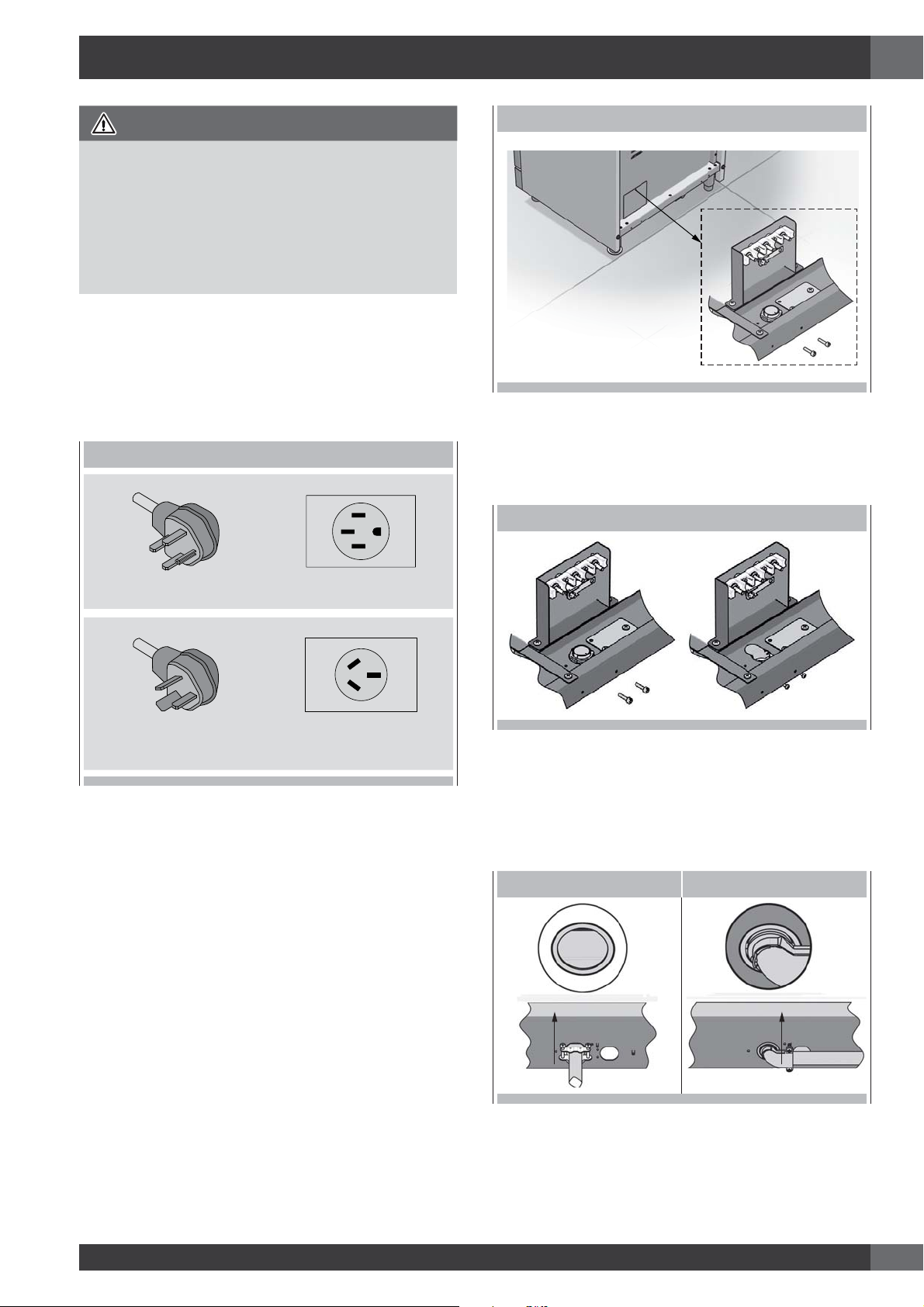
PLUG POWER SUPPLY CORD
LOCATION OF ELECTRICAL CONNECTION
3) Add strain relief if not provided.
NOTE: If necessary remove the knockout to insert the strain relief.
Power supply cord strain relief
• Assemble a UL listed strain relief in the opening.
UL LISTED STRAIN RELIEF
NEMA 14-50P Plug NEMA 14-50R Receptacle
NEMA 10-50P Plug
(for US only)
Power Supply Cord Kit or Flexible Conduit (for US only)
The user is responsible for connecting the power supply cord to
the connection block located behind the back panel access cover.
This appliance may be connected by means of permanent
“hard wiring” (flexible armored or nonmetallic shielded
copper cable), or by means of a power supply cord kit. Use
only a power supply cord kit rated at 125/250 volts minimum
and marked for use with ranges. Cord must have either 3 or
4 conductors. Terminals on end of wires must either be closed
loop or open-end spade lugs with upturned ends.
For 30” and 36” ranges use a power supply cord kit rated at
minimum 50A that is marked for use with nominal 1-3/8 in
(34.93 mm) diameter connection openings.
1) Disconnect power.
2) Remove the terminal block cover screws located on the back
of the range.
NEMA 10-50R Receptacle
(for US only)
• Feed the power supply cord or flexible conduit through
the strain relief in the cord/conduit plate on bottom of
range. Allow enough slack to easily attach the wiring to the
terminal block.
• Tighten strain relief screw against the power supply cord or
flexible conduit.
POWER SUPPLY CORD FLEXIBLE CONDUIT
4) Complete installation following instructions for your type of
electrical connection:
• 4-wire (recommended)
• 3-wire (if 4-wire is not available)
11
Page 14

EN
6 - Electrical connections
IF YOUR HOME HAS AND YOU WILL BE
CONNECTING TO:
4-wire receptacle
A UL listed, 250-
(NEMA type 14-50R)
50-amp, range
volt minimum,
power supply
cord
ELECTRICAL CONNECTION OPTIONS
CONNECTION
IF YOUR HOME HAS AND YOU WILL BE
TYPE:
3-wire receptacle
(NEMA type 10-50R)
CONNECTING TO:
A UL listed, 250-
volt minimum,
50-amp, range
power supply
cord
CONNECTION
TYPE:
4-wire direct
A fused
disconnect or
5"
(12.7 cm)
circuit breaker
box
TERMINAL BLOCK - GROUND STRAP
4-wire connection
Part of metal ground strap must be removed.
1) Use Phillips screwdriver to remove the ground-link screw
from the back of the range. Save the ground-link screw and
the end of the ground link under the screw.
2) Feed the power supply cord through the strain relief in the
cord/conduit plate on bottom of range. Allow enough slack
to easily attach the wiring to the terminal block.
3) Use Phillips screwdriver to connect the green ground wire
from the power supply cord to the range with the groundlink screw. The ground wire must be attached first.
4) Use 3/8” nut driver to connect the neutral (white) wire to the
enter terminal block post with one of the 10-32 hex nuts.
(Refer to the “Electric Connection Options” table to see the
appropriate connection type)
5) Connect line 1 (black) and line 2 (red) wires to the outer
terminal block posts with 10-32 hex nuts.
6) Securely tighten hex nuts.
7) Replace terminal block access cover.
3-wire direct
A fused
disconnect or
5"
(12.7 cm)
A. Metal ground strap
B. Ground-link screw
circuit breaker
box
3-wire connection
Use this method only if local codes permit connecting chassis
ground conductor to neutral wire of power supply cord:
1) Feed the power supply cord through the strain relief in the
cord/conduit plate on bottom of range. Allow enough slack
to easily attach the wiring to the terminal block.
2) Use 3/8 nut driver to connect the neutral (white) wire to the
center terminal block post with one of the 10-32 hex nuts.
(Refer to the “Electric Connection Options” table to see the
appropriate connection type)
3) Connect line 1 (black) and line 2 (red) wires to the outer
terminal block posts with 10-32 hex nuts.
4) Securely tighten hex nuts.
5) Replace terminal block access cover.
12
“30” INDUCTION RANGE 4-WIRE CONNECTION
A
B
D
C
A. Red
B. White
C. Green
D. Black
“30” INDUCTION RANGE 3-WIRE CONNECTION
A
C
B
A. Red
B. White
C. Black
Page 15
6 - Electrical connections
EN
“36” INDUCTION RANGE 4-WIRE CONNECTION
A
A. Green
B. Red
C
D
B
C. White
D. Black
“36” INDUCTION RANGE 3-WIRE CONNECTION
A
A. Red
B
B. White
C. Black
C
Direct Electrical Connection to the Circuit Breaker, Fuse Box or Junction Box
If the appliance is connected directly to the circuit breaker, fuse box or junction box, use flexible, armored or non metallic sheathed
copper cable (with grounding wire).
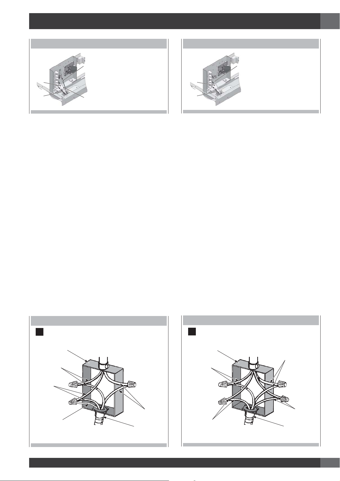
3-WIRE BRANCH CIRCUIT (for US only)
Refer to Figure A:
where local codes allow the connection of GROUND wire from
the range to the branch circuit NEUTRAL wire (gray or white
colored wire):
- If local codes permit, connect the green GROUND wire from
the range and the white wire from the oven to the branch
circuit NEUTRAL wire (gray or white colored wire).
- Connect the red and black leads from the range to the
corresponding leads in the junction box.
4-WIRE BRANCH CIRCUIT (for US only)
Refer to Figure B:
- Disconnect ground from neutral at free end of conduit.
- Connect the green GROUND wire from the range to the
GROUND wire in the junction box (bare or green colored
wire).
- Connect the red and black leads from the range to the
corresponding leads in the junction box.
- Connect the white wire from the range to the NEUTRAL (gray
or white) wire in the junction box.
DO NOT ground to a gas supply pipe.
DO NOT connect to electrical power supply until appliance is
permanently grounded. Connect the ground wire before turning
on the power.
GROUNDED NEUTRAL
A
Junction box
Red wires
White wires
Bare or
green wire
Cable from
power supply
Cable
from oven
Black wires
UL listed conduit
connector
DO NOT ground to a gas supply pipe.
DO NOT connect to electrical power supply until appliance is
permanently grounded. Connect the ground wire before turning
on the power.
UNGROUNDED NEUTRAL
B
Junction box Cable from
Red wires
Bare or
green wire
power supply
Cable
from oven
White wires
Black wires
UL listed conduit
connector
13
Page 16

EN
7 - Final checklist
CONNECTING TO 208 VOLT CIRCUIT
To prevent improper connections leading to damage of
electrical components and so voiding the warranty, the
following steps must be performed:
1. Check the electrical requirements and make sure you have
the correct electrical supply and that the range is properly
grounded.
2. Before the range is connected, turn on the power supply.
3. Check power at the junction box wires using a voltmeter
having a range of 0-250 VAC. If you have installed the
oven for use on 240 Volt supply, you should find that the
voltage reading between the black and red wires (Line to
Line) should be 220 to 240 Volts. If you have modified the
range(s) for use on 208 Volt, the voltage reading between
the black and red wires should be 190 to 208 Volts.
4 Connect the range to the power supply.
5. Set the clock by following these steps:
• Press
• Immediately press
• Press
• Immediately press
TIME
key twice until the display shows “SET TIME”.
+
or - keys to set hours.
TIME
key again to change minutes.
+
or - keys to set minutes, hold to
change by ten (10) minutes step.
• Press
TIME
key or wait for a few seconds.
Clock is now set.
This option is provided for areas where standard 240 Volt
service is not available. This option must be accessed with the
appliance connected to power source, and using the following
sequence:
1. Within five minutes from power up, hold
MENU
and
TIME
keys for 3 seconds to enter the user option menu. The
display shows as follows:
2. Hold then
TIME
and
LIGHT
keys until the display becomes
dark.
3. Hold
MENU
and
LIGHT
further, until the time display shows
“Volt” and temperature module shows “240” blinking,
waiting for an input.
4. Using + or - keys, the control toggles between 240V
MENU
and 208V options. Hold
5. Hold
TIME
and
LIGHT
keys in order to quit the selection.
to confirm.
6. Test the bake mode by following this step:
• Move cooking mode knob to “BAKE” position.
• Cooling fan, oven lights, preheat led will turn on.
• A beep is sounded when the oven reaches the preset
350 °F (175 °C) and the preheat light turn off.
• Move the knob back to “OFF” position to stop cooking.
7. To check the other oven functions refer to the “Using the
Oven Controls” section of the USE AND CARE MANUAL.
8. If the oven is working properly, turn off the power supply to
the oven.
9. Place the cover on the junction box and make sure the cover
is securely fastened and turn on the power to the oven.
IMPORTANT
Leave these INSTALLATION instructions as well as the USE
AND CARE MANUAL with the owner.
MENU
6. Hold
key for 3 seconds to quit the user option menu.
The voltage setting is stored and kept even after a long
power-off.
14
Page 17

Veuillez prêter attention à ces symboles que vous rencontrerez
dans ce manuel :
FR
TABLES DES MATIERES PAGE
1 -
Avertissement Spéciaux
Avant de Procéder à l’Installation
Installation autocaravane
2 -
Dimensions et Dispositions pour la Découpe
Instructions d’installation des supports anti-bascules
3 -
Consignes d’installation
4 -
Instructions d’Installation
Alimentation électrique
5 6 -
Connexions électriques
Connexion 4 fils
Connexion 3 fils 12
Connexion directement au disjoncteur, à la boîte
à fusibles ou à la boîte de jonction
7 - Liste de vérification finale 14
11
12
13
DANGER
2
2
2
3
5
6
7
9
Si vous ne suivez pas IMMEDIATEMENT ces instructions,
vous courez le risque de mourir ou d’être sérieusement
blessé.
AVERTISSEMENT
Ce symbole signifie que la sécurité est en danger. Il signale
les risques potentiels qui peuvent entraîner la mort ou des
blessures à l’opérateur ou aux autres.
Si vous ne suivez pas ces instructions à la lettre, vous courez
le risque de mourir ou d’être sérieusement blessé.
BIEN LIRE CES INSTRUCTIONS ET LES CONSERVER.
À l’installateur :
Laissez ces instructions avec l’appareil.
Au client :
Gardez ces instructions comme référence future.
IMPORTANT: Gardez ces instructions pour une utilization
d’inspection électrique locale
INSTALLATEUR: Veuillez laisser ce manuel au propriétaire
pour de futures références.
PROPRIETAIRE: Veuillez garder ce manuel pour de futures
références.
AVERTISSEMENT
Le respect minutieux des indications fournies dans ce manuel
est indispensable pour éviter le risque de feu ou d’explosion
susceptible d’endommager les biens et les produits et de
provoquer des blessures, voire même la mort.
Ne pas stocker ou utiliser de l’essence ou d’autres liquides
inflammables à proximité de cet appareil ou de tout autre
appareil électroménager.
1
Page 18

FR
1 - Avertissement Spéciaux
INSTRUCTION IMPORTANT
Avertissement Spéciaux
Veuillez lire les instructions avant toute utilisation
Il est de votre responsabilité d’installer l’appareil correctement.
Confiez l’installation de cette cuisinières à un technicien qualifié.
AVERTISSEMENT
- Respecter les règlements et ordonnances en vigueur.
- Avant l’installation de la cuisinière, noter le modèle et
les numéros de série. Les deux numéros se trouvent sur
la plaque de données dans la position indiquée dans la
figure ci-dessous.
POSITION DE LA PLAQUE SIGNALÉTIQUE
Vous pouvez demander une copie des standards répertoriés à:
** National Fire Protection Association One Batterymarch Park
Quincy, Massachusetts 02269
*** CSA International 8501 East Pleasant Valley Rd. Cleveland,
OH 44131 – 5575
Installation autocaravane
L’installation de cette table de cuisson doit être conforme
aux Normes de Construction et de Sécurité des Habitations,
titre 24 CFR, Partie 3280 (jadis la Norme Fédérale pour la
Construction et la Sécurité des Autocaravanes; titre 24HUD
partie 280); ou lorsque de telles normes ne sont pas
applicables, la Norme pour les Installations des Habitations
(Emplacements, Communautés et Structures Habitations),
ANSI 225.1 - dernière édition ou aux réglementations locales.
Au Canada, l’installation de cette table de cuisson doit être
conforme aux normes en vigueur CAN/CSA-Z240 - dernière
édition ou aux réglementations locales.
Avant de Procéder à l’Installation
• Vérifiez l’endroit où la cuisinières sera installée. La table de
cuisson ne doit pas se trouver dans une zone de courants
d’air forts, par exemple de fenêtres ou de portes ni près de
calorifères ou de ventilateurs.
• L’appareil doit nécessairement être relié à la terre. Voir
«Conditions requises électricité».
• Veuillez vous assurer que l’installation électrique est
adéquate et conforme à la Réglementation Électrique
Nationale ANSI/NFPA 70 – dernière édition** ou à la
Réglementation Électrique du Canada, C22.1 – 1982 et
C22.2 N° 01982 (ou dernière édition)*** et à tous les
règlements et ordonnances en vigueur localement.
2
Page 19

2 - Dimensions et Dispositions pour la Découpe
35
3/4
(9
1,0
)
DIMENSIONS DU PRODUIT
Modèles de cuisinière 30”
FR
29 3/4” (75,8)
35 3/4” (91,0)
9" (22,8) [optionnel]
3" ( 7,6) [optionnel]
1" ( 2,5)
3/8” (1)
29 3/4” (75,6)
27 1/2” (69,7)
25 3/4” ( 65,4)
27 1/4” ( 69,1)
7 3/8” (18,7)
1 3/8” (3,5)
À
3 3/8” (8,5)
Max. 37 1/4” (94,7)
Min. 35 3/8” (89,8)
47 3/4” (121,4)
3
Page 20

FR
2 - Dimensions et Dispositions pour la Découpe
DISPOSITIONS POUR LA DÉCOUPE
C
Min. 30” (76,2)
Jusqu’au bas
de la hotte
Min. 18” (45,7)
Max.
Min. 18” (45,7)
13” (33)
Min. 6”
(15,2)
Bordure minimale de 2 po (5,1)
depuis le mur pour l’alimentation
en gaz ou électrique
A
ÉLECTRIQUE
GAZ
B B
4” 3/4 (12,3)
3” (7,6)
Min. 6”
(15,2)
*Position suggérée des
équipements
La totalité de la surface du mur arrière ainsi que la surface se trouvant au-dessus de la table de cuisson doit être faite d’une matière ignifuge.
*Consulter les réglementations locales pour les exigences exactes de localisation.
LARGEUR D’OUVERTURE A & C B
Cuisinière 30 po 30" (76,2) 6” (15,2)
Cuisinière 36 po 36" (91.4) 7” (17.8)
ESPACE SUPPLÉMENTAIRES:
Pour une installation en îlot, maintenir une distance minimum
de 6,3 cm (2 ½ po) entre le bord et le dos du comptoir et
7,6 cm (3 po) minimum sur les côtés du comptoir (voir vue
de dessus).
Remarque: La distance par rapport aux matériaux non
combustible doit respecter les réglementations
locales ou, en l’absence de celles-ci, avec le
« National Fuel Gas Code », ANSI Z223.1/
INSTALLATION ÉBARBER
NFPA 54.
Dégagements minimums d’une construction:
Au-dessus de la surface de cuisson [au-dessus de 36 po (91,4 cm)]
• Côtés - 3 po (7,6 cm)
• Avec un dégagement latéral de 3 po (7,6 cm) ou moins,
les placards muraux ne mesurant pas plus de 13 po (33
cm) de profondeur doivent se trouver à 18 po (45,7 cm)
minimum au-dessus de la surface de cuisson.
• Les armoires murales juste au-dessus du produit doivent
se trouver à 30 po (76.2 cm) minimum au-dessus de la
surface de cuisson
• Arrière - 0 po avec dosseret de 3 po (7,6 cm).
4
DOS
min 2 1/2” (6,3)
min 3” (7,6) min 3” (7,6)
Page 21

2 - Dimensions et Dispositions pour la Découpe
FR
Avant de déplacer la cuisinière, protégez tout plancher fini et
fixez la (les) porte(s) du four en position fermée pour éviter tout
dommage.
Disposition de hotte d’extraction:
Il est recommandé d’installer nos cuisinières avec une hotte
d’extraction suspendue.
Installez une hotte disposant d’une capacité d’évacuation d’au
moins 450 CFM.
Cet appareil produisant une importante quantité de chaleur,
vous devez porter une attention toute particulière à l’installation
de la hotte et de la conduite d’aération afin de vous assurer
qu’elle répond aux normes de construction en vigueur dans
votre region.
AVERTISSEMENT
Il faut prévoir les dégagements ci-dessous par rapport
aux surfaces horizontales qui se trouvent au-dessus de la
cuisinière.
Le non-respect de cette consigne pourrait présenter un risque
d’incendie.
• Pour les installations dépourvues de hotte, prévoyez un
espace minimum de 30” (76 cm) entre l’appareil et tout
élément inflammable situé au-dessus de celui-ci.
• Il est possible d’installer une hotte spéciale à proximité
d’éléments horizontaux inflammables dans la mesure
où celle-ci dispose d’une fonction de mise en marche
automatique.
• Pour obtenir les spécifications relatives aux espaces
d’autres installations pourvues d’une hotte, veuillez vous
reporter aux instructions fournies avec celle-ci
AVERTISSEMENT
Pour vérifier que la bride anti-basculement est bien installée et engagée:
• Faire glisser la cuisinière vers l’avant.
• Vérifier que la bride antibasculement est bien fixée au plancher
ou au mur.
• Faire de nouveau glisser la cuisinière vers l’arrière de sorte que le
pied de la cuisinière se trouve sous la bride antibasculement.
• Voir les instructions d’installation pour plus de détails.
Bride antibasculement
Pied de la cuisinière
INSTALLATION DE LA BRIDE ANTI-BASCULEMENT
MUR
ARRIÈRE
PAROI LATÉRALE
DE L'ARMOIRE
ANCRAGE
AU MUR
ATTENTION
Ces cuisinières pèsent plus de 180 kg. Afin d’éviter tout
risque de blessure ou d’endommagement de l’appareil et
compte tenu du poids et de la taille de la cuisinière:
DEUX PERSONNES SONT NÉCESSAIRES POUR UNE
INSTALLATION ADÉQUATE DES CUISINIÈRES.
Instructions d’installation des supports anti-bascules
AVERTISSEMENT
Risque de basculement
Un enfant ou une personne adulte peut faire basculer la cuisinière, ce
qui peut causer un décès. S’assurer que le dispositif antibascule est
réengagé lorsque la plage est déplacée.
Ne pas faire fonctionner la cuisinière si la bride antibasculement n’est
pas installée et engagée. Le non-respect de ces instructions peut causer
un décès ou des brûlures graves aux enfants et aux adultes.
ÉGALITÉ
ANTIBASCULEMENT
SUPPORT
Pour les constructions en ciment ou béton:
Vous devez utiliser les éléments fixationappropriés (non
fournis). Fixez le support sur le sol et/ou le mur à l’aide les 4
vis à bois (fournies).
Le support anti-basculement devrait être inséré dans
l’ouverture de l’équerre antibasculement sur la cuisinière.
5
Page 22

FR
3 - Consignes d’installation
AVERTISSEMENT
• Risque du fait du poids excessif
Soyez à deux personnes ou plus pour porter et installer la
cuisinières. Sinon, vous risquez de vous blesser au dos ou
de subir d’autres blessures.
• Risque de coupure
Méfiez-vous des bords tranchants et des extrémités du
polystyrène lorsque vous portez le produit. Sinon, vous
risquez de vous couper ou de vous faire légèrement mal.
Ne pas boucher le flux d’air au niveau de l’ouverture
de ventilation du four ni au-dessous du panneau frontal
inférieur de la cuisinière. Éviter de toucher les ouvertures
de ventilation ou les surfaces voisines car ces surfaces
pourraient se réchauffer pendant que le four est en service.
CHOIX DE LA POSITION DE LA CUISINIÈRE
Choisissez attentivement l’emplacement d’installation de la
cuisinière.
La cuisinière doit être positionnée pour être utilisée dans la
cuisine, mais loin des courants d’air.
Une porte ou une fenêtre ouvertes, l’air mis en mouvement par
les ventilateurs de chauffage/climatisation peuvent causer des
courants d’air forts.
LES OUTILS DONT VOUS AUREZ BESOIN
NOTE IMPORTANTE
Si vous installez la cuisinière contre une surface combustible,
veillez à prévoir un minimum de rehausse.
Respectez toutes les distances par rapport aux surfaces
combustibles qui sont indiquées dans les pages précédentes
Avant de déplacer la cuisinière, protégez le sol et fixez la porte
du four en position fermée afin de prévenir tout dommage.
Évitez absolument de soulever ou de porter la cuisinière en la
tenant par la poignée de la porte.
Pour éliminer le risque de brûlure ou d’incendie à cause
d’une surchauffe de la surface des unités, évitez de placer
une armoire de rangement au-dessus de l’unité. Si vous avez
une armoire au-dessus de la cuisinière, vous pouvez réduire
le risque en installant à une certaine distance au-dessous de
la partie inférieure de l’armoire un écran de protection qui
projette horizontalement.
Avant de commencer l’installation, enlevez les matériaux
d’emballage et les manuels d’explication sur la table de
cuisson; puis retirez du manuel d’explication, les instructions
concernant l’installation et lisez-les avec attention.
MATÉRIEL FOURNI
SUPPORT
ANTIDÉRAPANT,
ÉQUERRE ET VIS
6
Page 23

4 - Instructions d’Installation
FR
ÉTAPE 1
Coupez les bandes et retirez l’appareil de la palette à l’aide
d’une transpalette à main en introduisant la fourche sous le
bloc de mousse.
ATTENTION
Tenez-vous à distance. Les extrémités des bandes coupées
pourraient se retourner contre vous.
ÉTAPE 3
Portez la cuisinière à l’intérieur. Avant d’installer les pieds,
placez l’appareil près de son emplacement d’installation finale
car les pieds ne sont pas adaptés pour déplacer l’appareil sur
de longues distances.
Les pieds sont emballés séparément sous carton.
ATTENTION
Les portes et les passages portant au lieu d’installation doivent
avoir une ouverture d’au moins 31’’. Si l’ouverture est de moins
de 31’’, il est nécessaire d’enlever la porte du four et les boutons
de commande (voir le manuel d’utilisation et d‘entretien pour
les instructions de démontage de la porte du four).
Remarque: Dans la partie postérieure, monter les pieds à collier
de façon à ce qu’ils s’enclenchent dans le dispositif
anti-retournement.
ÉTAPE 2
Prenez les instructions d’installation présentes sur la cuisinière
et lisez-les attentivement avant de commencer.
ÉTAPE 4
Avec la base en mousse encore en place, faites basculer la
cuisinière latéralement et visser la première paire de pattes.
7
Page 24

FR
4 - Instructions d’Installation
ÉTAPE 5
Retirez la transpalette, inclinez la cuisinière latéralement pour
visser la deuxième paire de pieds. Enlevez la base.
ÉTAPE 7
Après les raccordements électriques et de gaz (voir les
paragraphes d’instructions correspondants), mesurez la
hauteur aux quatre coins pour vérifier si le sol est nivelé.
Ajustez les pattes de nivellement à la hauteur souhaitée et
assurez-vous que la cuisinière est nivelée. Tournez la partie
inférieure de chaque patte dans le sens anti-horaire pour lever
la patte et dans le sens horaire pour la baisser. Assurez-vous
que le sol est protégé. Faites glisser l’unité de façon à engager
la bride anti-basculement.
ÉTAPE 6
Installez le dosseret (si fourni) au moyen de trois vis dans la
partie postérieure et la plinthe
3”9”
ÉTAPE 8
Accrochez les pattes au bas de la plinthe dans les fentes de
chaque côté du cadre et tournez vers le haut jusqu’à ce que
les clips sur le haut de la plinthe s’enclenchent correctement.
REMARQUE : Veiller à ce que la plinthe soit bien fixée
8
Page 25

5 - Alimentation électrique
FR
Avant d’installer le four, faites vérifier par un électricien
compétent que votre installation électrique domestique est
correcte et qu’en ajoutant le four, vous n’allez pas surcharger
le circuit de dérivation sur lequel il est installé. Votre appareil
doit être convenablement installé et connecté à la terre par
un électricien qualifié. Demandez à votre revendeur de vous
conseiller un technicien qualifié ou un centre de réparation
agréé. Cet appareil est fabriqué avec un câble de TERRE
vert connecté avec le bâti du four. Position de la boîte de
raccordement ou de la boîte encastrée. Pour la position
suggérée de la boîte de raccordement ou de la boîte
encastrée, voir le paragraphe « Exigences de découpe ».
POSITION DE LA PLAQUE SIGNALÉTIQUE
AVERTISSEMENT
Risque de choc électrique, bâti mis à la terre connecté au
neutre de l’appareil à travers un lien
Il est interdit d’effectuer la mise à la terre à travers le
conducteur neutre pour l’installation d’un circuit de
dérivation neuf (1996 NEC); les maisons mobiles et les
véhicules de loisirs, ou dans une zone dans laquelle la mise
à la terre à travers le conducteur neutre est interdite. Pour
installations dans lesquelles la mise à la terre à travers le
conducteur neutre est interdite :
- Déconnecter la terre du neutre à l’extrémité libre du
circuit.
- Utiliser le terminal de mise à la terre ou le porter jusqu’à
l’unité de mise à la terre.
- Utiliser le terminal neutre ou le porter jusqu’au neutre du
circuit de dérivation en procédant comme d’habitude.
Le four est conçu pour être raccordé à une alimentation
électrique à trois ou quatre fils, monophasée, 120/240 ou
120/208 Volt, 60 Hz AC , sur un circuit séparé doté de
fusibles sur les deux côtés de la ligne (il est recommandé
de prévoir un sectionneur ou un fusible temporisé). Ne pas
installer de fusible sur le neutre.
Les normes et réglementations locales prévalent sur ces
instructions.
Effectuez les connexions électriques conformément aux
normes et réglementations locales. Un raccord de conduit
conforme UL doit être prévu à chaque extrémité du conduit
d’alimentation électrique (à la cuisinière et à la boîte de
raccordement).
• Les dimensions des fils et les connexions doivent être
adaptées aux valeurs nominales de la cuisinière.
États-Unis:
Assurez-vous que les branchements électriques et ceux
de mise à la terre ainsi que la taille des câbles soient
conformes à la dernière édition du code américain National
Electrical Code, ANSI/ NFPA 70 et aux standards et aux
règlementations locales.
Canada:
Assurez-vous que l’alimentation électrique et les dimensions
des fils sont adaptées et conformes au CSA Standard
C22.1, Canadian Electrical Code, Part 1 -dernière édition
et tous les codes et réglementations locaux.
REMARQUE: POUR UTILISATION AVEC TENSION
D’ALIMENTATION 208 V, 60 HZ, VOIR LES
RACCORDEMENTS À UN CIRCUIT 208 V.
EXIGENCES ÉLECTRIQUES CUISINIÈRES À UN FOUR 30”
Alimentation électrique
Service
Intensité électrique
Charge max. de
connexion
Fil d’alimenation min. L1, L2, mis à la terre 8 AWG
EXIGENCES ÉLECTRIQUES CUISINIÈRES À UN FOUR 30”
Alimentation électrique
Service
Intensité électrique
Charge max. de
connexion
Fil d’alimenation min. L1, L2, mis à la terre 8 AWG
(*) Puissance limitée à 50.0 Amp
120/240 ou 120/208 volts CA, 60 Hz
circuit dédié de 50 ampères
120/240V 45.8 Ampères
120/208V 48.5 Ampères
120/240V 11.00 kW
120/208V 10.00 kW
Neutre
120/240 ou 120/208 volts CA, 60 Hz
circuit dédié de 50 ampères
120/240V 61.0 Ampères
120/208V 63.0 Ampères
120/240V 14.60 kW
120/208V 13.30 kW
Neutre
10 AWG
10 AWG
9
Page 26

FR
5 - Alimentation électrique
AVERTISSEMENT
DANGER D’ELECTROCUTION
• L’alimentation électrique du circuit du branchement du
apareil doit être coupée lorsque les connexions des
lignes sont mises en place.
• N’utilisez pas de cordon d’extension avec cet appareil.
• Une mise électrique à la terre est nécessaire pour cet
appareil.
• L’extrémité libre du fil vert (le fil de garde) doit être
connectée à la masse appropriée. Ce fil doit rester
branchée à la masse au apareil.
• Si un tuyau d’eau froide est interrompu par un plastique,
des joints non métalliques; des connexions d’union ou
d’autres matériaux isolants. NE L’UTILISEZ pas pour
mettre à la masse.
• Ne branchez pas la masse à un tuyau à gaz.
• N’AYEZ PAS de fusible en position neutre ou un circuit
à la masse.
• Un fusible dans un circuit neutre ou à la masse pourrait
entraîner une électrocution.
• Vérifiez avec un électricien qualifié si vous avez un
doute si votre appareil est correctement raccordé à la
masse.
• Si vous ne suivez pas bien ces instructions, cela peut
entraîner des blessures graves ou la mort.
10
Page 27

6 - Connexions électriques
FR
CAUTION
Ne réparez ou ne remplacez pas des pièces de l’appareil si
ce n’est pas spécifiquement recommandé dans le manuel.
Tous les autres dépannages doivent être effectués par un
technicien qualifié. Ce qui réduirait les risques de blessures et
d’endommagements du apareil. Ne modifiez jamais ou n’altérez
jamais la construction de l’appareil en enlevant des panneaux,
des couvertures de fil, des vis, ou toute autre pièce du produit.
Câble d’alimentation électrique branché à l’usine
Votre cuisinière est équipée d’un câble d’alimentation installé à
l’usine. Le câble doit être raccordé à une prise mise à la terre de
120/240 V ou 120/208 V. S’il n’y a pas de prise disponible, faitesen installer une par un électricien qualifié.
CABLE DE ALIMENTACIÓN ELÉCTRICA
POSICIÓN DEL EMPALME ELÉCTRCO
3) Ajouter le dispositif de décharge si non fourni.
REMARQUE: si nécessaire, enlever le prédécoupé pour mettre en
place le dispositif de décharge.
Dispositif de décharge du cordon d’alimentation électrique
• Installer dans l’ouverture un dispositif de décharge homologué UL.
AÑADIR EL DISPOSITIVO DE
DESCARGA SI NO HA SIDO ENTREGADO
NEMA 14-50P Plug NEMA 10-50P Plug
NEMA 14-50R Receptacle NEMA 10-50R Receptacle
(solamente para US)
Cordon d’alimentation électrique ou conduit flexible (uniquement
pour US)
L’utilisateur est responsable du branchement du cordon d’alimentation
électrique au bloc de raccordement qui se trouve derrière le portillon
d’accès du panneau postérieur. L’appareil doit être raccordé avec
un cordon d’alimentation électrique. Utiliser uniquement un cordon
d’alimentation à 125/250 V min. et adapté à l’utilisation avec des
cuisinières. Le cordon doit avoir 3 ou 4 conducteurs. Les terminaux
à l’extrémité des câbles doivent être fermés en boucle ou par des
cosses à fourche à extrémités recourbées.
Pour les cuisinières de 30” et 36”, utiliser un cordon d’alimentation
calibré à au moins 50A destiné à être utilisé avec des ouvertures de
connexion de diamètre nominal de 1-3/8 in (34.93 m).
1) Débrancher l’alimentation.
2) Enlever les vis du couvercle de la plaque à bornes située dans la
partie postérieure de la cuisinière.
• Introduire le cordon d’alimentation ou le conduit flexible à travers
le dispositif de décharge jusqu’à la plaque située sur le fond de la
cuisinière. Laisser suffisamment de jeu pour fixer confortablement
le câblage à la plaque à bornes.
• Serrer la vis du dispositif de décharge contre le câble d’alimentation
électrique ou le conduit flexible.
CABLE DE ALIMENTACIÓN TUBO FLEXIBLE
4) Terminez l’installation en suivant les instructions adaptées à votre
type de connexion électrique :
• 4 fils (recommandé)
• 3 fils (si la connexion à 4 fils n’est pas disponible)
11
Page 28

FR
6 - Connexions électriques
SI VOTRE CONNEXION
RÉSIDENTIELLE EST:
4 fils réceptacle (NEMA
type 14-50R)
ET VOUS ALLER
CONNECTER À:
homologué UL
A, 250 V min.,
50 A, cordon
d’alimentation de
la cuisinière
OPTIONS DE CONNEXION ÉLECTRIQUE
TYPE DE
CONNEXION:
SI VOTRE CONNEXION
RÉSIDENTIELLE EST:
3 fils réceptacle
(NEMA type 10-50R)
ET VOUS ALLER
CONNECTER À:
homologué UL
A, 250 V min.,
50 A, cordon
d’alimentation de
la cuisinière
TYPE DE
CONNEXION:
4 fils déconnecteur
à fusible direct
A ou boîte de
5"
(12.7 cm)
disjoncteurs
BORNIER – CÂBLE DE TERRE
Connexion 4 fils
Enlever une partie de tresse de masse métallique.
1) À l’aide d’un tournevis Philips, enlever la vis de raccordement de terre
de la partie arrière de la cuisinière. Garder la vis de raccordement
de terre et l’extrémité du raccordement de terre sous la vis.
2) Acheminer le cordon d’alimentation électrique à travers le dispositif
de décharge jusqu’à la plaque pour cordon/conduit située sur
le fond de la cuisinière.Laisser suffisamment de jeu pour fixer
confortablement le câblage à la plaque à bornes.
3) À l’aide du tournevis Philips, connecter le câble vert de terre du
cordon d’alimentation électrique à la cuisinière moyennant la vis
de raccordement de terre. Fixer d’abord le câble de terre.
4) À l’aide d’un tournevis à douille 3/8” , connecter le câble neutre
(blanc) au bloc à bornes d’entrée moyennant un écrou hexagonal
10-32. (Consulter le tableau « Options de connexion électrique »
pour le type de raccordement approprié)
5) Raccorder les câbles ligne 1 (noir) et ligne 2 (blanc) au bloc à
bornes extérieur avec des écrous hexagonaux 10-32.
6) Serrer à fond les écrous hexagonaux.
7) Remettre en place le portillon d’accès au bloc à bornes.
3 fils déconnecteur
à fusible direct
A ou boîte de
5"
(12.7 cm)
A.
Tresse de masse métallique
B. Vis de raccordement de terre
disjoncteurs
Connexion 3 fils
N’utiliser cette méthode que si les réglementations locales permettent
de raccorder le conducteur de terre du bâti au câble neutre du cordon
d’alimentation électrique:
1) Introduire le cordon d’alimentation à travers le dispositif de
décharge jusqu’à la plaque située sur le fond de la cuisinière.
Laisser suffisamment de jeu pour fixer confortablement le câblage
à la plaque à bornes.
2) À l’aide d’un tournevis à douille 3/8” , connecter le câble neutre
(blanc) au bloc à bornes d’entrée moyennant un écrou hexagonal
10-32.
(Consulter le tableau « Options de connexion électrique » pour le
type de raccordement approprié)
3) Raccorder les câbles ligne 1 (noir) et ligne 2 (rouge) au bloc à
bornes extérieur avec des écrous hexagonaux 10-32.
4) Serrer à fond les écrous hexagonaux.
5) Remettre en place le portillon d’accès au bloc à bornes.
12
CONNEXION À 4 FILS GAMME INDUCTION “30”
A
B
D
C
A. Rouge
B. Blanc
C. Vert
D. Noir
CONNEXION À 3 FILS GAMME INDUCTION “30”
A
C
B
A. Rouge
B. Blanc
C. Noir
Page 29

6 - Connexions électriques
FR
CONNEXION À 4 FILS GAMME INDUCTION “36”
A
A. Vert
B. Rouge
C
D
B
C. Blanc
D. Noir
CONNEXION À 3 FILS GAMME INDUCTION “36”
A
A. Rouge
B
B. Blanc
C. Noir
C
Connexion directement au disjoncteur, à la boîte à fusibles ou à la boîte de jonction
Si l’appareil est raccordé directement au disjoncteur, à la boîte à fusibles ou à la boîte de jonction, utiliser un câble en cuivre engainé flexible,
blindé ou non métallique (avec câble de mise à la terre).
3-CÂBLAGE DU CIRCUIT DE DÉRIVATION (US seulement)
Voir la figure A pour toute consultation :
Si les codes locaux permettent de raccorder le fil de TERRE de la
cuisine au fil NEUTRE du circuit de dérivation (fil gris ou blanc) :
- Si les réglementations locales le permettent, raccorder le câble vert
de TERRE partant de la cuisinière et le câble blanc allant du four au
fil NEUTRE di circuit de dérivation (fils gris ou blanc).
- Connecter les fiches noire et rouge de la cuisinière aux
correspondantes sur la boîte de jonction.
4-CIRCUIT DE DÉRIVATION 4 FILS (US seulement)
Voir la figure B pour toute consultation :
- Déconnecter la terre du neutre à l’extrémité libre du conduit.
- Raccorder le fil de TERRE vert de la cuisine au fil de TERRE de la
boîte de jonction (fil nu ou vert).
- Connecter les fiches noire et rouge de la cuisinière aux
correspondantes sur la boîte de jonction.
- Raccorder le fil blanc de la cuisinière au NEUTRE (gris ou blanc)
de la boîte de jonction.
NE PAS effectuer le raccordement de terre sur un tuyau d’amenée de gaz.
NE PAS connecter à l’alimentation électrique tant que l’appareil n’a
pas été mis à la terre de façon permanente. Connecter le fil de terre
avant de mettre l’appareil sous tension.
NEUTRE MIS À LA TERRE
A
Boîte de jonction
Fils rouges
Fils blancs
Fils vert ou
dénudés
Cable de
l’alimentation
Cable
du four
Fils noir
Connecteur de
conduit listé U.L.
NE PAS effectuer le raccordement de terre sur un tuyau d’amenée de gaz.
NE PAS connecter à l’alimentation électrique tant que l’appareil n’a
pas été mis à la terre de façon permanente. Connecter le fil de terre
avant de mettre l’appareil sous tension.
NEUTRE NON MIS À LA TERRE
B
Boîte de jonction Cable de
Fils rouges
Fils vert ou
dénudés
l’alimentation
Cable
du four
Fils blancs
Fils noir
Connecteur de
conduit listé U.L.
13
Page 30

FR
7 - Liste de vérification finale
Afin d’éviter des erreurs de raccordement pouvant porter à la
détérioration des composants électriques et à la perte d’effet
de la garantie, suivre les indications suivantes :
1. Vérifier les conditions électriques requises et s’assurer que
l’alimentation électrique est correcte et que la cuisinière est
mise à la terre correctement.
2. Avant que la cuisinière ne soit branchée, branchez
l’alimentation principale.
3. Vérifier l’arrivée de courant aux câbles de la boîte de
jonction à l’aide d’un voltmètre ayant une plage de travail
de 0-250 VAC. Si vous avez installé le four pour l’utiliser
sous une alimentation de 240 V, le voltage affiché entre les
fils noir et rouge (ligne à ligne) devrait être compris entre
220 et 240 V. Si vous avez modifié la cuisine pour l’utiliser
sous 208 V, le voltage affiché entre les fils noir et rouge
devrait être compris entre 190 et 208 V.
4 Branchez la cuisinière à la source d’alimentation.
5. Régler la minuterie en procédant comme suit :
TIME
• Pressez la touche
jusqu’à ce que la mention « SET
TIME » s’affiche.
• Pressez immédiatement les touches
+
ou - pour
régler l’heure.
• Appuyez encore sur le bouton
TIME
pour changer les
minutes.
• Presser immédiatement les touches
+
ou - pour
régler les minutes; maintenir enfoncé pour changer de
10 en 10 minutes.
• Pressez
TIME
ou attendez quelques secondes.
La minuterie est maintenant réglée.
6. Testez le mode de cuisson en procédant de la manière
suivante :
• Placez le bouton de mode de cuisson sur la position «
BAKE ».
• Le ventilateur de refroidissement, les lumières du four et le
voyant de préchauffage s’allument.
• Un bip sonore indique que le four a atteint la température
de consigne de 350° °F (175° °C) et le voyant de
préchauffage s’éteint.
• Reporter le bouton à la position « OFF » pour interrompre
la cuisson.
CONNEXION A UN CIRCUIT DE 208 VOLT
Cette option existe pour les régions où le standard de 240 Volt
n’est pas disponible. Il faut accéder à cette option quand le
apareil est branché à une source d’alimentation, et en utilisant
les séquences suivantes :
1. Dans les cinq minutes après avoir allumé le apareil, appuyés
sur les clés
MENU
et
TIME
pendant 3 secondes pour entrer
le menu option menu utilisateur. L’affichage indique ce qui
suit :
2. Appuyez sur les clés
TIME
et
LIGHT
jusqu’à ce que l’écran
nes’assombrisse.
3. Appuyez encore sur
MENU
et
LIGHT
, jusqu’à ce
quel’affichage horaire indique “Volt” et que le module
températureclignote un “240”, attendant une entrée.
4. En utilisant les clés + ou -, la commande alterne
entre lesoptions 240V et 208V. Appuyez sur
MENU
pour
confirmer.
5. Maintenez les clés
TIME
et
LIGHT
afin de quitter la
sélection.
MENU
6. Maintenez la clé
pendant 3 secondes pour quitter
lemenu option utilisateur.
Le réglage de la tension est enregistré et gardé même après
unelongue coupure.
7. Pour tester les autres fonctions du four, consulter la section «
UTILISATION DES COMMANDES DU FOUR » du manuel
d’utilisation et d’entretien.
8. Si le four fonctionne correctement, couper l’alimentation
électrique.
9. Mettre le couvercle sur la boîte de jonction et veiller à ce
qu’elle soit bien fixée, puis rallumer l’alimentation électrique
du four.
AVERTISSEMENT
Laissez ces instructions d’INSTALLATION et le MANUEL
D’UTILISATION ET D’ENTRETIEN au propriétaire.
14
Page 31

Preste la debida atención a los siguientes símbolosque
encontrará en el manual:
ES
TABELA DE CONTENIDO
1 - Advertencias Especiales 2
Antes de comenzar la instalación 2
Instalación en Casas Móviles 2
2 - Dimensiones del Producto y de Encastre 3
Instructions d’installation des supports
anti-bascules 5
3 - Información de instalación 6
4 - Instrucciones para la Instalación 7
5 - Alimentación eléctrica 9
6 - Conexiones eléctricas 11
Conexión de 4 cables 12
Conexión de 3 cables 12
Conexión directa al disyuntor, a la caja de
fusibles o a la caja de conexión. 13
7 - Lista de verificación final 14
PAG E
PELIGRO
Si no sigue estas instrucciones de forma INMEDIATA, puede
correr peligro de muerte o de resultar gravemente herido.
ADVERTENCIA
• Este es el símbolo de los avisos relacionados con la
seguridad: alerta sobre potenciales peligros que pueden
derivar en muerte o daños a las personas.
• Si no sigue estas instrucciones, puede correr peligro de
muerte o de resultar gravemente herido.
LEA Y CONSERVE ESTAS INSTRUCCIONES.
Instalador:
Deje las instrucciones con el electrodoméstico.
Cliente:
Conserve las instrucciones como referencia futura.
IMPORTANTE: Guarde estas instrucciones para el uso del
inspector eléctrico local.
INSTALADOR: Por favor, deje este manual a propietario para
futuras consultas.
PROPIETARIO: Por favor, conserve este manual para futuras
consultas.
ADVERTENCIA
• La inobservancia de las indicaciones recogidas en
este manual puede derivar en muerte o en daños a las
personas.
• No almacene ni utilice gasolina u otros vapores o líquidos
inflamables cerca de este ni otro electrodoméstico.
1
Page 32

ES
1 - Advertencias Especiales
INSTRUCCIONES IMPORTANTE
Por favor, lea todas las instrucciones antes de utilizar este aparato.
Efectuar una instalación adecuada es responsabilidad suya.
Asegúrese de que el electrodoméstico es instalado por un
técnico cualificado.
IMPORTANTE
- Cumpla todas las normativas y ordenanzas vigentes aplicables.
- Antes de instalar la cocina, comprobar el modelo y los
números de serie. Los dos números se encuentran en la placa
de datos en la posición indicada en la figura a continuación
POSICIÓN DE LA PLACA DE SEÑALIZACIÓN
Puede obtener copias de las normas citadas en:
** National Fire Protection Association One Batterymarch Park
Quincy, Massachusetts 02269
*** CSA International 8501 East Ple0asant Valley Rd. Cleveland,
OH 44131-5575
Instalación en Casas Móviles
La instalación de esta placa de cocina debe cumplir con
el título 24 CFR, Parte 3280 de las Normas de seguridad
y construcción de viviendas prefabricadas o móviles
estadounidenses (Manufactured Home Construction and Safety
Standards, [anteriormente denominada Federal Standard for
Mobile Home Construction and Safety (Norma federal para
seguridad y construcción de casas prefabricadas), Title 24
HUD, Part 280]; o, en caso de que dicha norma no sea
aplicable, deberá seguirse la pauta marcada por la Norma
para instalaciones en casas prefabricadas estadounidense
[(Standard for Manufactured Home Installations (Manufactured
Home Sites, Communities and Setups], ANSI A225.1 (última
edición) o bien, la normativa local existente referente a casas
móviles.
En Canadá, la instalación de esta placa de cocción debe
cumplir con las normativas actuales CAN/CSA-Z240 (última
edición) o con las normativas locales.
Antes de comenzar la instalación
• Examine el lugar en el que va a instalar la placa de cocción.
Debe ubicarla en un lugar alejado de fuertes corrientes de
aire, como ventanas, puertas y ventiladores.
• Es necesario que el electrodoméstico se conecte a una toma
de tierra. Consulte la sección “Conexión eléctrica. Requisitos”.
• Debe asegurarse de que la instalación es adecuada y
conforme con el Código eléctrico americano (National
Electrical Code), ANSI/NFPA 70 (última edición**) o con
el Código eléctrico canadiense (Canadian Electrical Code),
C 22.1 – 1982 y C22.2 Nº 01982 (o la última edición)***
y con todos los códigos y ordenanzas locales.
• Debe asegurarse de que la conexión de gas está conforme
con los códigos y ordenanzas locales.
2
Page 33

2 - Dimensiones del Producto y de Encastre
35
3/4
(9
1,0
)
DIMENSIONES DU PRODUCTO
Modelos de cocina de 30” de ancho
ES
29 3/4” (75,8)
35 3/4” (91,0)
9" (22,8) [opcional]
3" ( 7,6) [opcional]
1" ( 2,5)
3/8” (1)
29 3/4” (75,6)
27 1/2” (69,7)
25 3/4” ( 65,4)
27 1/4” ( 69,1)
7 3/8” (18,7)
1 3/8” (3,5)
A
3 3/8” (8,5)
Max. 37 1/4” (94,7)
Min. 35 3/8” (89,8)
47 3/4” (121,4)
3
Page 34

ES
2 - Dimensiones del Producto y de Encastre
DIMENSIONES DE ENCASTRE
C
Min. 18” (45,7)
Min. 6”
(15,2)
2” (5,1) máxima protuberancia
de la pared al suministro
elèctrico o de gas.
Min. 30” (76,2)
A la parte inferior
de la campana
de ventilaciòn
A
GAS
B B
4” 3/4 (12,3)
3” (7,6)
ELÉCTRICA
Max. 13” (33)
Min. 18” (45,7)
Min. 6”
(15,2)
*Posición sugerida
para los equipos
La supercie de toda la pared trasera sobre la cocina y por debajode la capucha debe cubrirse con un material no combustible.
*Consultar las normas locales para la exigencias exactas de colocación.
ANCHO DE APERTURA A & C B
Estufa de 30” 30" (76,2) 6” (15,2)
Estufa de 36” 36" (91.4) 7” (17.8)
ESPACIOS ADICIONALES:
Para la instalación de la isla, deje un espacio mínimo de
2-½” entre la abertura y el extremo trasero de la mesada y
un mínimo de 3” entre la abertura y los extremos laterales de
la mesada (ver la vista superior).
Nota: La distancia con relación a los materiales no
combustibles debe respetar las normas locales o, en
ausencia de las mismas, el « National Fuel Gas Code
», ANSI Z223.1/NFPA 54.
INSTALACIÓN AL RAS DEL CANTO DE LA ISLA
Distancia mínima a construcciones:
Por arriba de la supercie de cocinar (más de 36” [91.4 cm])
• Lados - 3” (7.6 cm).
• Dentro del espacio lateral de 3” (7.6 cm), los gabinetes
de la pared no más profundos de 13” (33.0 cm) deben
estar a un mínimo de 18” (45.7 cm) por arriba de la
supercie de cocinar.
• Los gabinetes de la pared que estén directamente por
encima del producto deben estar a un mínimo de 30”
(76.2 cm) por arriba de la supercie de cocinar.
• Parte posterior - 0” a la pared posterior de 3” (7.6 cm).
4
PARTE POSTERIOR
min 2 1/2” (6.3)
min 3” (7.6) min 3” (7.6)
Page 35

2 - Dimensiones del Producto y de Encastre
ES
Antes de mover la estufa, proteja cualquier suelo acabado y
asegúrese de que la puerta del horno esté cerrada para que
no se dañe.
Combinaciones de capuchas de ventilación:
Se recomienda que estas cocinas se instalen en conjunto con
una adecuada capucha de ventilación aérea.
Instale una capucha de por lo menos 450 CFM (pies cúbicos
por minuto).
Debido a la elevada capacidad de calor de esta unidad, debe
prestarse especial atención a la instalación de la capucha y
de la red de conductos para garantizar que cumpla con los
códigos de construcción locales.
ADVERTENCIA
Distancias respecto de superficies horizontales sobre la
cocina, medidas en relación a la superficie de cocción.
No cumplir con esto puedo provocar un peligro de incendio.
• Las instalaciones sin capucha requieren un mínimo de 30”
(76) respecto de elementos combustibles.
• Una instalación de capucha a medida con superficies
expuestas horizontales combustibles debe contar con una
función de encendido automático.
ADVERTENCIA
Para comprobar que el taco anti-vuelco está instalado y acoplado:
• Deslice la cocina hacia delante.
• Compruebe si el taco anti-vuelco está fijado firmemente al suelo
o a la pared.
• Deslice la cocina hacia atrás de tal manera que la pata trasera
se encuentre debajo del taco anti-vuelco.
• Para más detalles, consulte las instrucciones de instalación.
Taco anti-vuelco
Pata de la cocina
• Para otras instalaciones con una capucha, consulte las
instrucciones de instalación de capuchas sobre espacios
específicos para capuchas.
PRECAUCIÓN
Estas cocinas pesan hasta 400 libras. Desmontar algunos
elementos reducen su peso en forma considerable. Debido
al peso y tamaño de la cocina y para reducir el riesgo de
lesiones personales o daños al producto:
SE REQUIEREN DOS PERSONAS PARA UNA
INSTALACIÓN.
Instructions d’installation des supports anti-bascules
ADVERTENCIA
Peligro de vuelco
El vuelco de la cocina es un riesgo para todos, niños y adultos, que
puede llegar a provocar la muerte. Cuando se desplace la cocina,
comprobar que el taco anti-vuelco está acoplado. No dejar que la
cocina funciona sin el taco anti-vuelco instalado y acoplado. El no
respeto de estas instrucciones puede provocar quemaduras graves o
incluso la muerte para todos, niños y adultos.
INSTALACIÓN DE LA BRIDA ANTI- VUELCO
PARED DE
FIJACIÓN
PARED LATERAL
DEL GABINETE
A RAS
PARED
TRASERA
SOPORTE
ANTIVUELCO
Para construcciones de concreto o cemento: Deben
utilizarse elementos de sujeción apropiados (no provistos).
Sujete el soporte a la pared y/o piso mediante por lo
menos 4 tornillos para madera (provistos).
El soporte anti- Volcaduras se debe insertar en la abertura
correspondiente a la abrazadera anti-volcaduras de la
cocina.
5
Page 36

ES
3 - Información de instalación
ADVERTENCIA
• Peligro por peso excesivo
Dos personas o más tienen que desplazar e instalar la
cocina.
De lo contrario podrían sufrir daños en la espalda u otros.
• Peligro de corte
Cuidado con las aristas cortantes. Al desplazar el
producto, agarrarlo por los protectores de poliestireno.
De lo contrario podrían sufrir heridas leves o cortes.
ELECCIÓN DE LA POSICIÓN DE LA COCINA
Elija con atención la posición de la cocina.
La cocina se debe colocar en una posición que permita una
utilización práctica, pero alejada de corrientes de aire fuertes.
Una puerta o una ventana abiertas, el aire en movimiento por
ventiladores de calefacción/refrigeración pueden originar
fuertes corrientes de aire.
No taponar los flujos de aire en combustión a nivel de la
apertura de ventilación del horno ni debajo de panel frontal
inferior de la cocina. Evitar tocar las aperturas de ventilación
o las superficies cercanas ya que estas superficies podrían
calentarse mientras que el horno está funcionando.
Es indispensable que haya un aire fresco para una buena
combustión en el quemador.
NOTA IMPORTANTE
HERRAMIENTAS NECESARIAS
Retire el embalaje y separe los manuales de instrucciones
antes de comenzar la instalación.
Lea atentamente los manuales de instalación antes de
comenzar.
Si instala la cocina contra una superficie combustible,
prevea un mínimo de realce Respete todas las distancias
con relación a las superficies combustibles indicadas en las
páginas anteriores.
Antes de desplazar la cocina, proteja el suelo y mantenga la
puerta del horno cerrada para prevenir cualquier daño.
Evitar absolutamente levantar o agarrar la cocina sujetándola
por el asa de la puerta Para eliminar el riesgo de quemaduras
o de incendio a causa de un calentamiento de la superficie de
la unidades, evitar colocar un armario encima de la unidad.
Si tiene un armario encima de la cocina, puede reducir el
riesgo instalando a una cierta distancia por debajo de la parte
inferior del armario una pantalla de protección que recubra
toda la superficie horizontal
MATERIALES PROVISTOS
SOPORTE
ANTIVOLCADURAS,
A BRAZADERA
Y TORNILLOS
6
Page 37

4 - Instrucciones para la Instalación
ES
PASO 1
Cortar las bandas y sacar el aparato del palet con un transpalet
de mano introduciendo la horquilla por debajo del bloque de
gomaespuma.
ATENCIÓN
Mantenerse alejado. Los extremos de las bandas cortadas
podrían golpearle al darse la vuelta.
PASO 3
Llevar la cocina al interior. Antes instalar las patas, ponen el
aparato cerca de su lugar de instalación final ya que las patas
no son adecuadas para desplazar el aparato sobre distancias
largas.
Las patas están embaladas por separado debajo de la caja.
ATENCIÓN
Las puertas y los pasos que conducen al lugar de instalación
deben tener una abertura de 31” por lo menos. Si la
abertura es menor de 31”, es necesario quitar la puerta del
horno y los botones de mando (ver el manual de utilización
y de mantenimiento para las instrucciones de desmontaje de
la puerta del horno).
ADVERTENCIA : En la parte trasera, montar las patas a collar
de manera que se enganchen en el dispositivo
anti-vuelco.
PASO 2
Tomar las instrucciones de instalación presentes en la cocina y
leerlas atentamente antes de empezar.
PASO 4
Sin haber retirado todavía la base de espuma, hacer bascular
la cocina hacia un lado y atornillar el primer par de patas.
7
Page 38

ES
4 - Instrucciones para la Instalación
PASO 5
Retirar el transpalet, inclinar la cocina de lado para atornillar
el segundo par de patas. Retirar la base.
PASO 7
Tras realizar las conexiones de electricidad y de gas (ver los
párrafos de instrucciones correspondientes), medir la altura
en las cuatro esquinas para comprobar que el aparato está
bien nivelado, Regular las patas de nivelación y enganchar el
dispositivo anti-vuelco.
PASO 6
Instalar la parte dorsal (si se entrega) por medio de tres tornillos
en la parte trasera y el pinto.
3”9”
PASO 8
Empujar el zócalo hasta que quede correctamente encajado.
NOTA: Comprobar que el zócalo está acoplado de forma segura
8
Page 39

5 - Alimentación eléctrica
ES
Antes de instalar el horno, hacer que un electricista competente
verifique que su instalación eléctrica doméstica es correcta y
que al añadir el horno, no se pueda producir una sobrecarga
en el circuito de derivación en el que está instalado.
Su aparato debe estar instalado adecuadamente y ser
conectado a tierra por un electricista cualificado.
Pida a su vendedor que le aconseje un técnico cualificado o
un centro de reparación autorizado.
Este aparato está fabricado con un cable de TIERRA verde
conectado con la caja de conexiones y la caja empotrada de
la estructura del horno.
Para la posición sugerida de la caja de conexiones o de la
caja empotrada, ver el párrafo “Exigencias de corte”.
POSICIÓN DE LA PLACA DE SEÑALIZACIÓN
ADVERTENCIA
Riesgo de electrocución, bastidor puesto a tierra conectado
al neutro del aparato a través de un enlace.
Está prohibido efectuar la toma de tierra a través de un
conductor neutro para la instalación de un circuito de
derivación nuevo (1996 NEC); las casa móviles y los
vehículos de ocio, o en una zona en la que la toma de
tierra a través de del conductor neutro está prohibida.
Para instalaciones en las que la toma de tierra a través
del conductor neutro está prohibida:
- Desconectar la tierra del neutro en el extremo libre del
circuito.
- Utilizar el terminal de toma de tierra o llevarlo hasta la
unidad de toma de tierra.
- Utilizar el terminal neutro o llevarlo hasta el neutro del
circuito de derivación operando como de costumbre.
El horno está concebido para ser empalmado a una
alimentación eléctrica de tres o de cuatro cables,
monofásica, 120/240 o120/208 Voltios, 60 Hz AC , en
un circuito separado dotado de fusibles en los dos lados de
la línea (se recomienda prever un seccionador o un fusible
temporizado). No instalar fusible en el neutro.
Hay que respetar prioritariamente sobre estas instrucciones
las normas y las reglas locales.
Efectuar las conexiones eléctricas conformemente a las
normas y a las reglas locales.
Un empalme de conducto conforme UL tiene que estar
previsto en cada extremo del conducto de alimentación
eléctrica (a la cocina o a la caja de conexiones).
• Las dimensiones de los cables y las conexiones deben
estar adaptadas a los valores nominales de la cocina
Estados Unidos:
Comprobar que la alimentación eléctrica y las dimensiones
de los cables son adecuadas y conformes con el « National
Electrical Code », ANSI/ NFPA 70-última edición y con
todos los códigos y reglamentaciones locales.
Canadá:
Comprobar que la alimentación eléctrica y las dimensiones
de los cables son adecuadas y conformes con el « CSA
Standard C22.1, Canadian Electrical Code, Part 1 »-última
edición y con todos los códigos y reglamentaciones locales
ADVERTENCIA : PARA LA UTILIZACIÓN CON TENSIÓN
DE ALIMENTACIÓN DE 208 V, 60 HZ, VER
LOS EMPALMES CON UN CIRCUITO DE
ì208 V.
REQUISITOS ELÉCTRICOS ESTUFAS CON HORNO 30”
Suministro eléctrico
Servicio
Total de amperes
Carga máxima
conectada
Cable de suministro
mínimo
REQUISITOS ELÉCTRICOS ESTUFAS CON HORNO 36”
Suministro eléctrico
Servicio
Total de amperes
Carga máxima
conectada
Cable de suministro
mínimo
(*) Limitación de energía a 50.0 Amps
120-240V o 120-208V, 60 Hz
Circuito dedicado de 50 amperes
120/240V
120/208V
120/240V
120/208V
L1, L2, a tierra - 8 AWG
Neutro - 10 AWG
120-240V o 120-208V, 60 Hz
Circuito dedicado de 50 amperes
120/240V
120/208V
120/240V
120/208V
L1, L2, a tierra - 8 AWG
Neutro - 10 AWG
45.8
Amperes
48.5
Amperes
11.00
kW
10.00
kW
61.0
Amperes
63.0
Amperes
14.60
kW
13.30
kW
9
Page 40

ES
5 - Alimentación eléctrica
ADVERTENCIA
PELIGRO DE ELECTROCUCIÓN
• La alimentación eléctrica del circuito derivado del aparato tiene
que desconectarse cuando se están realizando las conexiones
de la línea.
• No utilice alargadores con el aparato.
• El aparato precisa de una toma de puesta a tierra. El final
libre del hilo verde (el hilo de tierra) tiene que conectarse con
una toma de tierra apropiada. Este hilo tiene que permanecer
conectado a tierra al aparato.
• Si la línea de agua fría se interrumpe con empaques de plástico,
no con juntas de estanquidad metálicas, conexiones de unión o
materiales aislantes, NO utilice para la puesta a tierra.
• NO conecte a tierra a la tubería del gas.
• NO tenga un fusible en el circuito de NEUTRO o de TIERRA.
• Un fusible en el circuito de NEUTRO o en el de TIERRA puede
provocar descargas eléctricas.
• Consulte con un electricista cualificado en el caso de que tenga
alguna duda si su aparato está bien conectado a tierra.
• Equivocarse al seguir estas instrucciones puede provocar
heridas graves o la muerte.
10
Page 41

6 - Conexiones eléctricas
ES
PRECAUCIÓN
No repare o remplace ninguna parte del aparato si no está
específicamente recomendado en el manual. Todas las demás
operaciones de mantenimiento tiene que realizarlas un técnico
cualificado. Para reducir el riesgo de heridas personales o daños
al aparato.
Nunca modifique o altere la construcción del aparato eliminando
paneles, forros de hilos, tornillos o cualquier otra parte del producto.
Cable de alimentación eléctrica conectado en fábrica
Su cocina está equipado con un cable alimentación eléctrica
conectado en fábrica El cable debe estar conectado a un
enchufe con toma de tierra de 120/240 V o de 120/208 V.
Si no existe un enchufe disponible, haga que un electricista
cualificado lo instale.
CABLE DE ALIMENTACIÓN ELÉCTRICA
NEMA 14-50P Plug NEMA 10-50P Plug
POSICIÓN DEL EMPALME ELÉCTRCO
3) Añadir el dispositivo de descarga si no ha sido entregado.
ADVERTENCIA : si es necesario, retirar el pre-recorte
para poner en su lugar el dispositivo de
descarga.
Cable de alimentación eléctrica o conducto flexible (solamente
para US
• Añadir el dispositivo de descarga si no ha sido entregado.
AÑADIR EL DISPOSITIVO DE
DESCARGA SI NO HA SIDO ENTREGADO
NEMA 14-50R Receptacle NEMA 10-50R Receptacle
(solamente para US)
Cable de alimentación eléctrica o conducto flexible (solamente
para US)
El utilizador es responsable de la conexión del cable
de alimentación eléctrica al bloque de empalme que se
encuentra detrás de la portezuela de acceso al panel trasero.
El aparato debe estar empalmado con un cable de
alimentación eléctrica. Utilizar solamente un cable de
alimentación a 125/250 V min. y adaptado para utilizarlo
con cocinas. El cable debe tener 3 o 4 conductores. Los
terminales del extremo de los cables deben estar cerrados en
círculo o terminales de horquilla con extremos curvados. Para
las cocinas de 30” et 36”, utilizar un cable de alimentación
calibrado al menos a 50A para ser utilizado con aberturas de
conexión con diámetro nominal de 1-3/8 en (34.93 m.
1) Desconectar la alimentación.
2) Retirar los tornillos de la tapa de la placa de bornes
situada en la parte trasera de la cocina.
• Introducir el cable de alimentación o el conducto flexible a
través del dispositivo de descarga hasta la placa situada
en el fondo de la cocina. Dejar un juego suficiente para
fijar cómodamente el cableado en la placa de bornes.
• Apretar el tornillo del dispositivo de descarga contra el
cable de alimentación eléctrica o el conducto flexible.
CABLE DE ALIMENTACIÓN TUBO FLEXIBLE
4) Terminar la instalación siguiendo las instrucciones
adecuadas a su tipo de conexión eléctrica:
• 4 cable (recomendada)
• 3 cables (si la conexión con 4 cables no está
disponible)
11
Page 42

ES
SI SU CONEXIÓN
RESIDENCIAL ES:
4 cables con receptáculo
(NEMA tipo 14-50R)
6 - Conexiones eléctricas
OPCIONES DE CONEXIÓN ELÉCTRICA
Y SE VA A
CONECTAR A:
homologado UL
A, 250 V min.,
50 A, cable de
alimentación de la
cocina
TIPO DE
CONEXIÓN:
SI SU CONEXIÓN
RESIDENCIAL ES:
3 cables con receptáculo
(NEMA tipo10-50R)
Y SE VA A
CONECTAR A:
homologado UL
A, 250 V min.,
50 A, cable de
alimentación de la
cocina
TIPO DE
CONEXIÓN:
4 cables
desconectador
con fusible directo
A o caja de
5"
(12.7 cm)
disyuntores
CAJA DE BORNES – CABLE DE TIERRA
Conexión de 4 cables
Quitar una parte de las trenzas de masa metálica.
1) Con la ayuda de un destornillador Philips, quitar el tornillo de
conexión de tierra de la parte trasera de la cocina. Guardar el
tornillo de conexión de tierra y el extremo de conexión de tierra
debajo del tornillo.
2) Introducir el cable de alimentación a través del dispositivo de
descarga hasta la placa situada en el fondo de la cocina. Dejar un
juego suficiente para fijar cómodamente el cableado en la placa de
bornes.
3) Con la ayuda de un destornillador Philips, conectar el cable verde
del cable de alimentación eléctrica a la cocina por medio del
tornillo de empalme de tierra. Fijar primero el cable de tierra.
4) Con la ayuda de un destornillador de 3/8”, conectar el cable
neutro (blanco)al bloque de bornes de entrada por medio de una
tuerca hexagonal 10-32.
(«Consultar el cuadro ”Opciones de conexión eléctrica” para el
tipo de empalme apropiado)
5) Conectar los cables de la línea 1 (negra) y la línea 2 (blanca) al
bloque de bornes exterior con tuercas hexagonales 10-32.
6) Apretar a fondo las tuercas hexagonales.
7) Colocar de nuevo la portezuela de acceso al bloque de bornes.
3 cables desconectador
con fusible directo
A o caja de
5"
(12.7 cm)
A.
Trenzas de masa metálica
B. Tornillo de conexión de tierra
disyuntores
Conexión de 3 cables
No utilizar este método nada más que si las normas locales permiten
empalmar el conductor de tierra de la estructura del cable neutro al
cable de alimentación eléctrica.
1) Introducir el cable de alimentación a través del dispositivo de
descarga hasta la placa situada en el fondo de la cocina. Dejar
un juego suficiente para fijar cómodamente el cableado en la
placa de bornes.
2) Con la ayuda de un destornillador de 3/8, conectar el cable
neutro (blanco) al bloque de bornes de entrada por medio de una
tuerca hexagonal 10-32.
(«Consultar el cuadro ”Opciones de conexión eléctrica” para el tipo
de empalme apropiado)
3) Conectar los cables de la línea 1 (negra) y la línea 2 (blanca) al
bloque de bornes exterior con tuercas hexagonales 10-32.
4) Apretar a fondo las tuercas hexagonales.
5) Colocar de nuevo la portezuela de acceso al bloque de bornes.
COCINA DE INDUCCIÓN DE 30” CON CONEXIÓN A 4 CABLES
A
B
D
C
A. Rojo
B. Blanco
C. Verde
D. Negro
12
COCINA DE INDUCCIÓN DE 30” CON CONEXIÓN A 3 CABLES
A
C
B
A. Rojo
B. Blanco
C. Negro
Page 43

6 - Conexiones eléctricas
ES
COCINA DE INDUCCIÓN DE 36” CON CONEXIÓN A 4 CABLES
A
A. Verde
B. Rojo
C
D
B
C. Blanco
D. Negro
COCINA DE INDUCCIÓN DE 36” CON CONEXIÓN A 3 CABLES
A
A. Rojo
B
B. Blanco
C. Negro
C
Conexión directa al disyuntor, a la caja de fusibles o a la caja de conexión.
Si el aparato está empalmado directamente al disyuntor, a la caja de fusibles o a la caja de conexión, utilizar un cable de cobre recubierto
flexible, blindado o no metálico (con cable de toma de tierra)
CIRCUITO DE DERIVACIÓN DE 3 CABLES (US solo)
Ver la figura A para cualquier consulta :
Si los códigos locales permiten empalmar el cable de TIERRA de
la cocina al cable NEUTRO del circuito de derivación (cable gris o
blanco):
- Si las normas locales lo permiten, empalmar el cable verde
de TIERRA que parte de la cocina y el cable blanco que va
desde el horno al cable NEUTRO del circuito de derivación
(cable gris o blanco).
- Conectar las clavijas negra y roja de la cocina a las
correspondientes en la caja de conexión.
CIRCUITO DE DERIVACIÓN DE 4 CABLES (solamente US)
Refer to Figure B:
Ver la figura B para cualquier consulta :
- Desconectar la tierra del neutro en el extremo libre del
conducto.
- Empalmar el cable de TIERRA verde de la cocina al cable de
TIERRA de la caja de conexión (cable desnudo o verde)
- Conectar las clavijas negra y roja de la cocina a las
correspondientes en la caja de conexión.
- Conectar el cable blanco de la cocina al NEUTRO (gris o
blanco) de la caja de conexión.
NO efectuar el empalme de tierra en un tubo de entrada de gas.
NO conectar la alimentación eléctrica mientras el aparato no
esté conectado a la tierra de manera permanente. Conectar el
cable de tierra antes de poner el aparato bajo tensión.
PUESTA A TIERRA DEL NEUTRO
A
caja de
empalme
hilo rojo
hilo blanco
hilo verde
o carne
cable desde
la alimentación
eléctrica
cable desde
el horno
hilo negro
conector de
conducto que figura
en la lista U.L.
NO efectuar el empalme de tierra en un tubo de entrada de gas.
NO conectar la alimentación eléctrica mientras el aparato no
esté conectado a la tierra de manera permanente. Conectar el
cable de tierra antes de poner el aparato bajo tensión.
NO PUESTA A TIERRA DEL NEUTRO
B
caja de
empalme
hilo rojo
hilo verde
o carne
cable desde
la alimentación
eléctrica
cable desde
el horno
hilo blanco
hilo negro
conector de
conducto que figura
en la lista U.L.
13
Page 44

ES
7 - Lista de verificación final
Para evitar errores de empalme que pueden originar el
deterioro de los componentes eléctricos y la pérdida de efecto
de la garantía, seguir las indicaciones:
1. Comprobar los requisitos eléctricos y asegurarse de que
la alimentación eléctrica es correcta y la cocina puesta a
tierra correctamente.
2. Antes de conectar la estufa, conecte la alimentación
eléctrica.
3. Comprobar la llegada de corriente a los cables de la caja
de conexión con un voltímetro 0-250 VAC. Si el horno ha
sido instalado para ser utilizado con una alimentación
de 240 V, el voltaje entre los hilos negro y rojo (línea a
línea) tendría que estar comprendido entre 220 y 240 V.
Si el horno ha sido instalado para ser utilizado con una
alimentación de 208 V, el voltaje entre los hilos negro y
rojo tendría que estar comprendido entre 190 y 208 V.
4 Conecte la estufa a la alimentación eléctrica.
5. Ajustar el reloj de la manera siguiente:
TIME
• Pulsar la tecla
• Pulsar inmediatamente las teclas
hasta que aparezca «SET TIME».
+
o - para ajustar
la hora.
TIME
• Pulsar otra vez el botón
• Pulsar inmediatamente las teclas
para cambiar los minutos.
+
o - para ajustar
los minutos; mantener apretado para cambiar los
minutos de 10 en 10.
TIME
• Pulsar
o esperar unos segundos.
CONEXIÓN A UN CIRCUITO DE 208 VOLTIOS
Esta opción se suministra para áreas en donde el servicio de
240 voltios estándar no se encuentra a disposición. Se tiene
que acceder a esta opción con el horno conectado a la toma
de corriente y utilizar la siguiente secuencia:
1. En el intervalo de cinco minutos después del encendido,
mantenga pulsadas las teclas
MENU
y
TIME
durante 3
segundos para acceder al menú de opciones de usuario.
La pantalla mostrará lo siguiente:
2. A continuación, mantenga pulsadas las teclas
LIGHT
hasta que la pantalla se oscurezca.
3. Mantenga pulsadas
MENU
y
LIGHT
durante más tiempo
TIME
y
hasta que la pantalla de hora muestre “Volt” y “240”
parpadee en el módulo de temperatura a la espera de una
entrada.
Ahora el reloj está regulado.
6. Probar el modo de cocción procediendo de la manera
siguiente:
• Situar el botón de modo de cocción en la posición
«BAKE».
• El ventilador de enfriamiento, las luces del horno y el
testigo de precalentamiento se encienden.
• Un bip sonoro indica que el horno ha llegado a la
temperatura de consigna de 350° °F (175° °C) y el
testigo de precalentamiento se apaga.
• Volver a poner el botón en la posición «OFF» para
interrumpir la cocción.
7. Para probar las otras funciones del horno, consultar la
sección «USO DE LOS MANDOS DEL HORNO» del
manual de uso y mantenimiento.
8. Si el horno funciona correctamente, cortar la alimentación
eléctrica.
9. Poner la tapa en la caja de conexión y comprobar que
está bien fijada antes de volver a encender la alimentación
eléctrica del horno.
4. Al utilizar las teclas + o -, el control conmutará entre
las opciones de 240 V y 208 V. Mantenga pulsada
MENU
para confirmar.
5. Mantenga pulsadas las teclas
TIME
y
LIGHT
para salir de
la selección.
MENU
6. Mantenga pulsada la tecla
durante 3 segundos
para salir del menú de opciones de usuario.
La configuración de voltaje se almacena y se guarda incluso
después de un largo apagado.
IMPORTANT
Dejar estas instrucciones de INSTALACIÓN y el MANUAL
DE USO Y MANTENIMIENTO al propietario.
14
Page 45

Note / Note / Nota
15
Page 46

Note / Note / Nota
16
Page 47

Page 48

09FL8061 ed 05/2018
 Loading...