

Page 1
F4CW36S1
F4CW30S1
F4UC30*1
F4UC36*1
F4PH30*1
F4PH36*1
HOOD
HOTTE DE CUSINE
CAMPANA DE COCINA
EN
FR
ES INSTRUCCIONES PARA LA INSTALACIÓN Y USO
INSTRUCTIONS FOR INSTALLATION AND USE
INSTRUCTIONS POUR L’INSTALLATION ET L’UTILISATION
Page 2
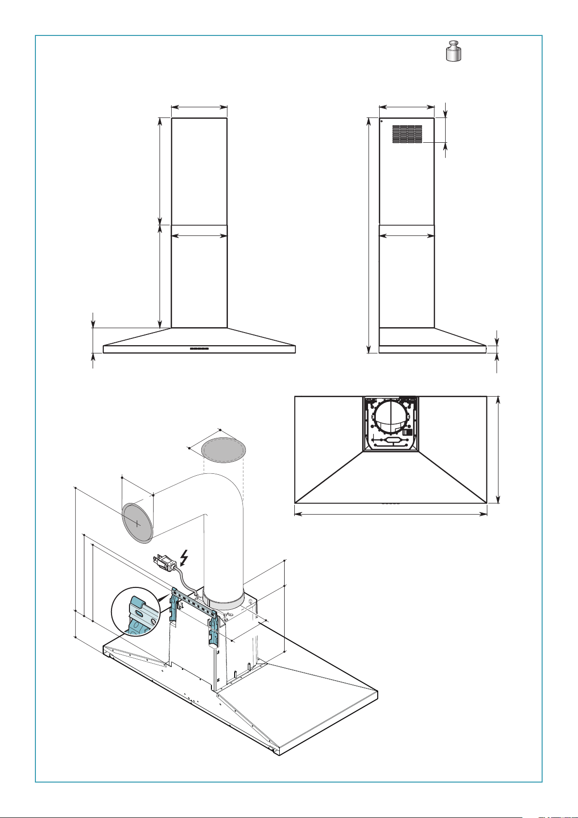
F4CW36S1
37lb - 17 kg
”
5/8
4
117mm
10
- 500mm
”
3/4
max 19
” - 480mm
7/8
18
1/4
” - 261mm
3/8
10
”
263mm
1/8
10
- 1097mm
”
1/4
max 43
” - 258mm
1/4
10
”
260mm
”
1/2
4
115mm
”
3/8
1
35mm
” - 480 mm
7/8
” - 340 mm
min. 18
3/8
13
”
5/8
4
117 mm
” - 322 mm
5/8
12
Ø5
7/8
150 mm
”
”
7/8
Ø5
150 mm
”
3/4
6
171 mm
3”
75 mm
”
3/8
10
265 mm
36” - 898mm
EN- cable length 5,0ft (1,5m)
FR- longueur de câble 5,0ft (1,5m)
ES- longueur de câble 5,0ft (1,5m)
” - 500mm
3/4
19
2
Page 3
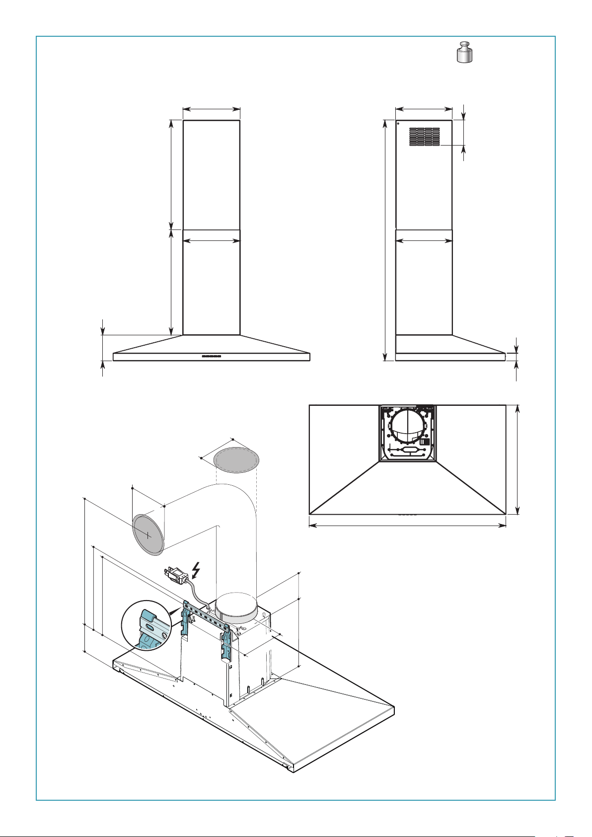
F4CW30S1
33lb - 15 kg
”
5/8
4
117mm
10
” - 500mm
3/4
max 19
” - 480mm
7/8
18
1/4
” - 261mm
3/8
10
263mm
1/8
10
” - 258mm
”
1/2
4
115mm
”
” - 1097mm
1/4
1/4
10
260mm
”
max 43
”
3/8
1
35mm
” - 480 mm
7/8
” - 340 mm
min. 18
3/8
13
”
5/8
4
117 mm
” - 322 mm
5/8
12
Ø5
7/8
150 mm
”
”
7/8
Ø5
150 mm
”
3/4
6
171 mm
3”
75 mm
”
3/8
10
265 mm
30” - 762mm
EN- cable length 5,0ft (1,5m)
FR- longueur de câble 5,0ft (1,5m)
ES- longueur de câble 5,0ft (1,5m)
” - 500mm
3/4
19
3
Page 4
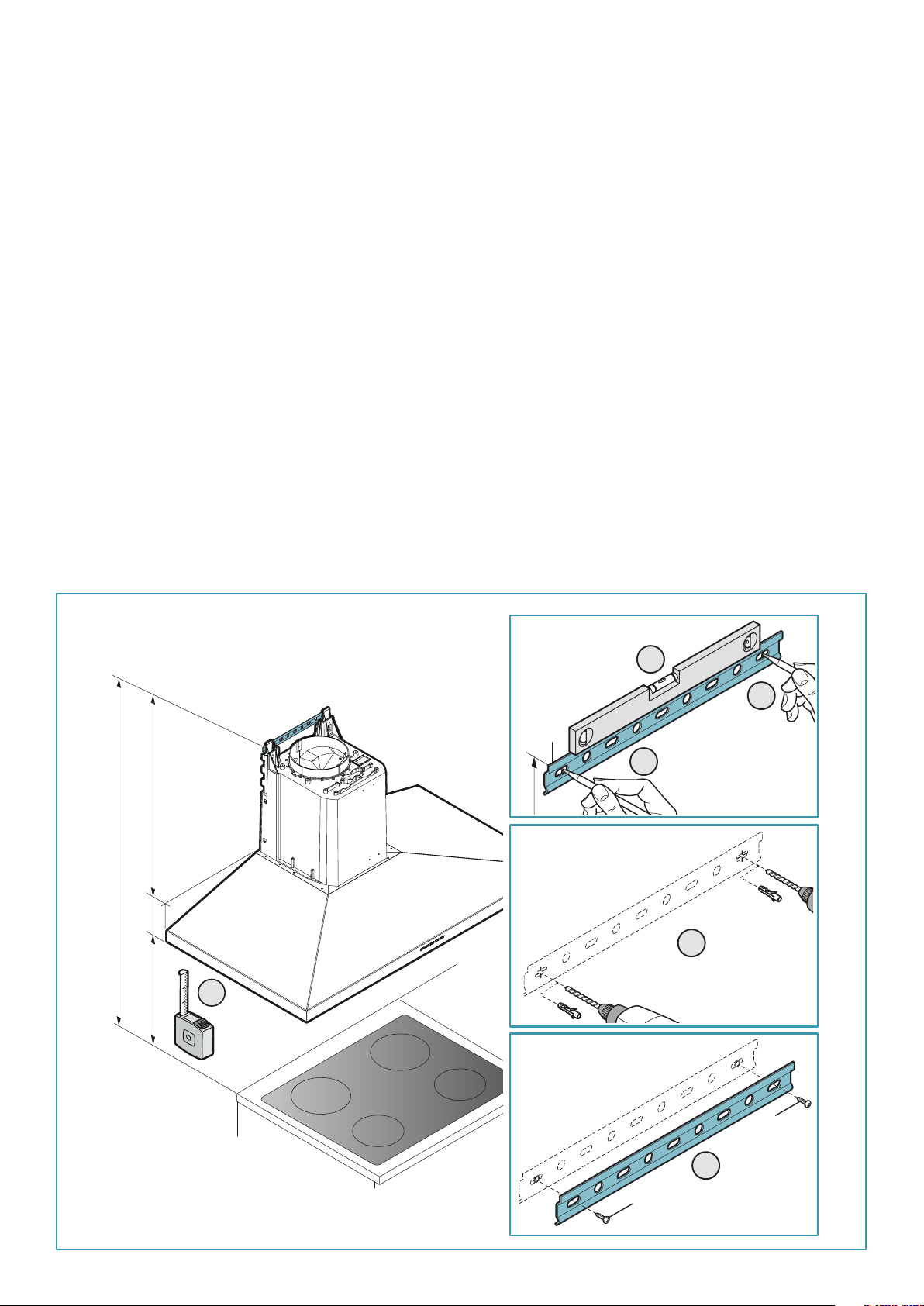
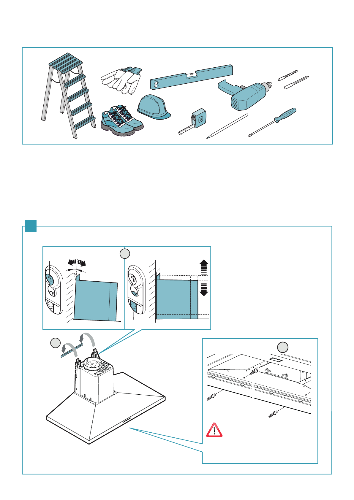
EN - Installation measurements
Recommended mounting height from cooking surface to hood bottom
is indicated by "A" in the drawing below. It is recommended to install the
hood in this range to optimize performance. It is recommended to not
exceed 35” (890mm) for dimension “A” as hoods mounted above this may
be difficult to reach for average height users and performance and efficiency will degrade. Hoods mounted below the lower measurement in
the “A” recommendation could result in damage due to heat and present a
fire hazard and would avoid any warranty claims attributable to the lower
mounting position. If available, also refer to the cooking appliance manufacturer’s height clearance recommendations and adhere to national and
local building and fire codes which supersede any recommendations stipulated herein.
ES - Medidas instalación
La altura de montaje recomendada desde la superficie de cocción hasta el
fondo de la campana se indica con una "A" en el dibujo siguiente. Se recomienda instalar la campana en este rango para optimizar el rendimiento. Se
recomienda no exceder 35" (890mm) para la dimensión "A" ya que las campanas montadas por encima de ésta pueden ser difíciles de alcanzar para
los usuarios de altura media y el rendimiento y la eficiencia se degradarán.
Las campanas montadas por debajo de la medida inferior de la recomendación "A" podrían resultar dañadas por el calor y presentar un riesgo de incendio, y evitarían cualquier reclamación de garantía atribuible a la posición de
montaje inferior. Si está disponible, consulte también las recomendaciones
de altura del fabricante del equipo de cocina y respete los códigos de construcción y contra incendios, nacionales y locales, que sustituyen cualquier
recomendación estipulada en el presente documento.
FR - Mesures pour installation
La hauteur de montage recommandée entre la surface de cuisson et la par-
tie inférieure de la hotte est indiquée par le « A » dans le dessin ci-dessous. Il
est recommandé d’installer la hotte dans cette plage pour optimiser sa performance. Il est recommandé de ne pas dépasser les 890 mm (35 po) pour
la dimension « A », car les hottes montées à une distance au-dessus peuvent
être difficiles à atteindre pour les utilisateurs de hauteur moyenne, et cela
diminuera leur performance et efficacité. Les hottes montées en-dessous
de la mesure inférieure de la recommandation « A » pourraient s’abîmer par
la chaleur et présenter un risque d’incendie, ce qui annulerait toute réclamation de garantie attribuable à la position de montage inférieure. Le cas
échéant, reportez-vous également aux recommandations du fabricant de
l’appareil de cuisson en ce qui a trait au dégagement en hauteur et respectez les codes du bâtiment et de prévention des incendies nationaux et
locaux qui remplacent toutes les recommandations stipulées dans le présent document.
H
” - 322 mm
5/8
12
”
5/8
4
117 mm
A
2
3
S
” - 322 mm
5/8
3
12
4
1
Ø 5/16” - 8 mm
A = 24" - 35"
610 mm - 890 mm
(RECOMMENDED FOR
OPTIMAL PERFORMANCE)
V1
5
V1
44
Page 5
EN- tool required
FR- outil requis
ES- herramienta requerida
ø
1/4
6 mm
”
EN - Hood fastening (1)
FR - Fixation de la hotte (1)
ES - Fijación de la campana (1)
1
B
ø
5/16
”
8 mm
2
C
1
3
V2 (x2)
EN - Mandatory safety screws.
FR - Vis de sécurité obligatoires.
ES - Tornillos de seguridad obligatorios.
5
Page 6
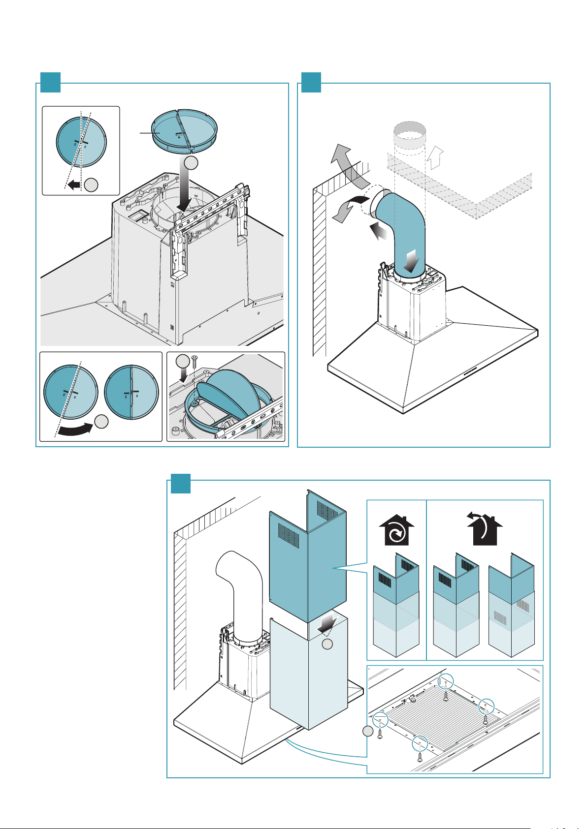
EN - Check valve installation (2)
and suction pipe assembly (3).
FR - Installation du clapet anti-retour (2)
et montage du tuyau d'aspiration (3).
2 3
M
2
1
ES - Instalación de la válvula antirretorno (2)
y montaje del tubo de aspiración (3).
3
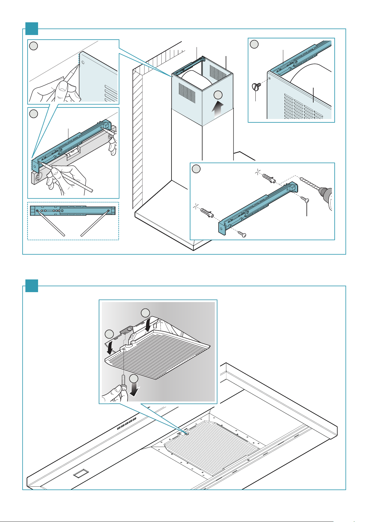
EN - Flue assembly.
FR - Montage de la cheminée.
ES - Montaje de la chimenea.
4
4
H
G
1
2
V3 (x4)
6
Page 7
5
2
L
H
5
L
H
1
V5
3
L
4
ø 1/4”
6mm
(x2)
ø 1/4”
6mm
ø 1/4”
6mm
V4 (x2)
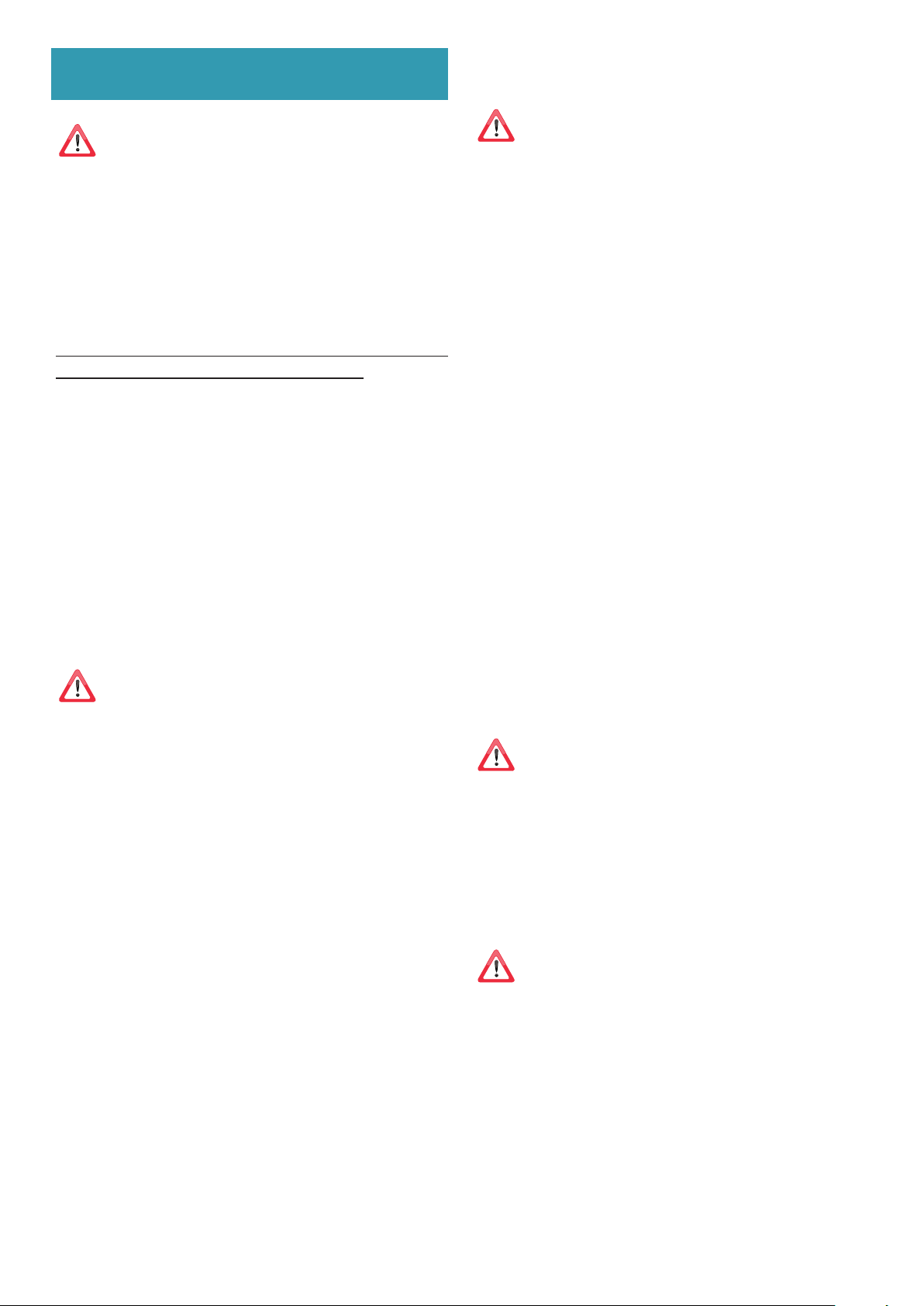
EN - Optional lter assembly FR - Montage du ltre en option ES - Montaje del ltro opcional
6
2
2
1
7
Page 8
SAFETY INSTRUCTIONS
AND WARNINGS
Installation operations are to be carried
out by skilled and qualied installers in accordance with the instructions in this booklet and in compliance with the regulations
in force.
DO NOT use the hood if the power supply cable
or other components are damaged: disconnect
the hood from the electrical power supply and contact the Dealer or an authorised Servicing Dealer for
repairs.
Do not modify the electrical, mechanical or
functional structure of the equipment.
Do not personally try to carry out repairs or
replacements. Interventions carried out by
incompetent and unauthorised persons can
cause serious damage to the unit or physical and
personal harm, not covered by the Manufacturer's
warranty.
ELECTRICAL SAFETY
The electrical system to which the hood is
to be connected must be in accordance
with local standards and supplied with
earthed connection in compliance with safety
regulations in the country of use. It must also
comply with European standards regarding radio
antistatic properties.
Before installing the hood, check that the electrical
mains power supply corresponds with what is reported on the identification plate located inside the hood.
The socket used to connect the installed equipment
to the electrical power supply must be within reach:
otherwise, install a mains switch to disconnect the
hood when required.
Any changes to the electrical system must be carried
out by a qualified electrician.
WARNINGS FOR THE INSTALLER
TECHNICAL SAFETY
Before installing the hood, check the integrity and function of each part. Should
anomalies be noted, do not proceed with
installation and contact the Dealer.
Do NOT install the hood if an aesthetic (or cosmetic) defect has been detected. Put it back into
its original package and contact the dealer.
No claim can be made for aesthetic (or cosmetic)
defects once it has been installed.
During installation, always use personal protective
equipment (e.g.: Safety shoes) and adopt prudent
and proper conduct.
The installation kit (screws and plugs) supplied with
the hood is only to be used on masonry walls: in case
of installation on walls of a different material, assess
other installation options keeping in mind the type
of wall surface and the weight of the hood (indicated
on page 2).
Keep in mind that installations with different types of
fastening systems from those supplied, or which are
not compliant, can cause electrical and mechanical
seal danger.
Do not install the hood outdoors and do not expose
it to atmospheric elements (rain, wind, etc.).
The maximum length of the flue fastening screws
(supplied by the manufacturer) must be 13 mm. Use
of non-compliant screws with these instructions can
lead to danger of an electrical nature.
Do not try to solve the problem yourself in the event
of equipment malfunction, but contact the Dealer or
an authorised Servicing Department for repairs.
When installing the hood, disconnect
the equipment by removing the plug or
switching o the main switch.
FUMES DISCHARGE SAFETY
Do no connect the equipment to discharge
pipes of fumes produced from combustion
(for example boilers, replaces, etc.).
Before installing the hood, ensure that all standards in
force regarding discharge of air out of the room have
been complied with.
8
Page 9

USER WARNINGS
USE AND CLEANING WARNINGS
These warnings have been drawn up for
your personal safety and those of others.
You are therefore kindly asked to read the
booklet carefully in its entirety before using the
or cleaning the equipment.
The Manufacturer declines all responsibility for
any damage caused directly, or indirectly, to persons, things and pets as a consequence of failing
to comply with the safety warnings indicated in
this booklet.
It is imperative that this instructions booklet is
kept together with the equipment for any future
consultation.
If the equipment is sold or transferred to another person, make sure that the booklet is also supplied so
that the new user can be made aware of the hood's
operation and relative warnings.
After the stainless steel hood has been installed, it
will need to be cleaned to remove any residues remaining from the protection adhesive as well as any
grease and oil stains which, if not removed, can cause
irreversible damage to the hood surface. To properly
clean the unit, the manufacturer recommends using
the supplied moist wipes, which are also available
sold separately.
Insist on original spare parts.
INTENDED USE
The equipment is solely intended to be used to
extract fumes generated from cooking food in
non-professional domestic kitchens: any other
use is improper. Improper use can cause damage
to persons, things, pets and exempts the Manufacturer from any liability.
Before cleaning or carrying out maintenance operations, disconnect the equipment by removing the plug or switching
o the main switch.
Do not use the hood with wet hands or bare feet.
Always check that all electrical parts (lights, extractor
fan) are off when the equipment is not being used.
The maximum overall weight of any objects placed
or hung (if applicable) on the hood must not
exceed 1.5 Kg.
Always supervise the cooking process during the use
of deep-fryers: Overheated oil can catch fire.
Do not leave open, unattended flames under the hood.
Do not prepare food over an open flame under
the hood.
Never use the hood without the metal anti-grease
filters: in this case, grease and dirt will deposit in the
equipment and compromise its operation.
Accessible parts of the hood can be hot when used at
the same time as the cooking appliances.
Do not carry out any cleaning operations when parts
of the hood are still hot.
There can be a risk of fire if cleaning is not carried out
according to the instructions and products indicated
in this booklet.
Disconnect the main switch when the equipment is
not used for long periods of time.
If other appliances that use gas or other fuels are being used at the same time (boiler,
stove, replaces, etc.), make sure the room
where the fumes are discharged is well-ventilated, in compliance with the local regulations.
ENGLISH
The equipment can be used by children over the age
of 8 and by persons with reduced physical, sensory
and mental abilities, or with no experience or knowledge, as long as they do so under supervision or after
having received relative instructions regarding safe
use of the equipment and understanding of the dangers connected to it.
Children are not to play with the equipment. Cleaning and maintenance by the user must not be carried
out by children without supervision.
9
Page 10

INSTALLATION
Intended only for qualied personnel
Before installing the hood,
carefully read the chapter
'SAFETY INSTRUCTIONS AND WARNINGS'.
TECHNICAL FEATURES
FUMES DISCHARGE
EXTERNAL EXHAUST HOOD SUCTION
In this version the fumes and vapours are discharged
outside through the exhaust pipe.
To this end, the hood outlet fitting must be connected
via a pipe, to an external output.
The technical specifications are exhibited on the labels located inside
the hood.
POSITIONING
The minimum distance between the highest part of the cooking
equipment and the lowest part of the hood is indicated in the installation instructions.
Should the instructions for the gas cooker specify a greater distance,
this must be taken into consideration.
Do not install the hood outdoors and do not expose it to outdoor environment (rain, wind, etc.).
ELECTRICAL CONNECTION
(Intended only for qualied personnel)
Disconnect the equipment from electrical mains power
supply before carrying out any operations on the hood.
Ensure that the wires inside the hood are not disconnected
or cut:
in the event of damage, contact your nearest Servicing Department.
Refer to qualied personnel for electrical connections.
Connection must be carried out in compliance with the provisions
of law in force.
Before connecting the hood to the electrical mains power supply,
check that:
• voltage supply corresponds with what is reported on the data plate
located inside the hood;
• the electrical system is compliant and can withstand the load (see
the technical specifications located inside the hood);
• the power supply plug and cable do not come into contact with
temperatures exceeding 158°F (70 °C);
• the power supply system is effectively and properly connected to
earth in compliance with regulations in force;
•
the socket used to connect the hood is within reach.
The outlet pipe must have:
• a diameter not less than that of the hood fitting.
• a slight slope downwards (drop) in the horizontal sections to prevent
condensation from flowing back into the motor.
• the minimum required number of bends.
• the minimum required length to avoid vibrations and reduce the
suction performance of the hood.
You are required to insulate the pipes if it passes through cold envi-
ronments.
In the presence of motors with 800m3/h or higher, a check valve is
present to prevent external air flowing back.
HOOD WITH INTERNAL RECIRCULATION FILTERING
In this model, the air passes through the charcoal filters
to be purified and recycled in the environment.
Ensure that the active carbon filters are assembled into
the hood, if not, install them as indicated in the assembly instructions.
In this version the check valve must not be assembled: remove
it if it is on the air outlet fitting of the motor.
ASSEMBLY INSTRUCTIONS
Intended only for qualied personnel
The hood can be installed in various congurations.
The generic assembly steps apply to all installations; for
each case, follow the specic steps provided for the required installation.
In case of:
• devices fitted with cables without a plug: the type of plug to use is
a ''standardised'' one. The wires must be connected as follows: yellow-green for grounding, blue for neutral and brown for the live. The
plug must be connected to an adequate safety socket.
•
fixed equipment not provided with a power supply cable and plug,
or any other device that ensures disconnection from the electrical
mains, with an opening gap of the contacts that enables total discon
nection in overvoltage category III conditions.
Said disconnection devices must be provided in the mains power
supply in compliance with installation regulations.
The cable must not be cut off by the switch.
The Manufacturer declines all responsibility for failure to comply with
the safety regulations.
-
10
Page 11

OPERATION
MAINTENANCE
WHEN TO TURN ON THE HOOD?
Switch on the hood at least one minute before starting to cook to direct
fumes and vapours towards the suction surface.
After cooking, leave the hood operating until complete extraction of all
vapours and odours. By means of the Timer function, it is possible to set
auto switch-off function which will allow the hood to turn off automatically after 15 minutes of operation.
WHICH SPEED IS TO BE SELECTED?
1st speed: maintains the circulation of clean air with low electricity
consumption.
2nd speed: normal conditions of use.
3rd speed: presence of strong odours and vapours.
4th speed: rapid disposal of odours and vapours.
WHEN SHOULD THE FILTERS BE WASHED OR REPLACED?
The metal filters must be cleaned every 30 hours of operation.
The active carbon filters must be replaced every 3-4 months, depending on the use of the hood.
For further details refer to the “MAINTENANCE” section.
ELECTRONIC PUSHBUTTON PANEL
Before cleaning or carrying out maintenance operations,
disconnect the equipment by removing the plug or
switching o the main switch.
Do not use detergents containing abrasive, acidic or corrosive
substances or abrasive cloths.
Regular maintenance guarantees proper operation and performance
over time.
Special attention is to be paid to the metal anti-grease lters : frequent cleaning of the filters and their supports ensures that no flammable grease is accumulated.
CLEANING OF EXTERNAL SURFACES
You are advised to clean the external surfaces of the hood at least once
every 15 days to prevent oily substances and grease from sticking to
them. To clean the brushed stainless steel hood, the Manufacturer recommends using "Magic Steel" wipes.
Alternatively and for all the other types of surfaces, it can be cleaned
using a damp cloth, slightly moistened with mild, liquid detergent or
denatured alcohol.
Complete cleaning by rinsing well and drying with soft cloths.
Do not use too much moisture or water around the push
button control panel and lighting devices in order to pre-
vent humidity from reaching electronic parts.
ENGLISH
Motor ON/OFF
Upon start-up, the speed is that stored at the previous operation.
Increase speed
from 1 to 4
Speed 4 is only active for a
few minutes, then speed 3
activates.
Reduce speed
from 4 to 1
Light on/o
TIMER (red LED flashing)
Auto switch-off after 15 min.
The function deactivates (red LED off) if:
- The TIMER key ( ) is pressed again.
- The ON/OFF key ( ) is pressed.
FILTER ALARM (red LED steady on with ( ) off)
Anti-grease filter maintenance after approximately 30 hours
of operation.
Press ( ) the meter for 3 seconds to reset.
The speeds are indicated by
the LEDs on the keys:
("+" LED flashing)
Speed 1
Speed 2
Speed 3
Speed 4
The glass panels can only be cleaned with specific, non-corrosive or
non-abrasive detergents using a soft cloth.
The Manufacturer declines all responsibility for failure to comply with
these instructions.
CLEANING OF INTERNAL SURFACES
Do not clean electrical parts, or parts related to the motor
inside the hood, with liquids or solvents.
For the internal metal parts, see the previous paragraph.
METAL ANTI-GREASE FILTERS
It is advised to frequently wash the metal filters (at least once a
month) leaving them to soak in boiling water and cleaning solution for
1 hour, taking care not to bend them.
Do not use corrosive, acid or alkaline detergents.
Rinse them well and wait for them to be completely dry before reassembling them.
Washing in a dishwasher is permitted, however, it may cause the filter
material to darken: to reduce the possibility of this problem from happening, use low-temperature washes (131°F / 55°C max.).
To extract and insert the metal anti-grease filters see the assembly instructions.
ACTIVE CARBON FILTERS
These filters retain the odours in the air that passes through them. The
purified air is recirculated into the environment.
The active carbon filters must be replaced on average every 3-4 months
under normal conditions of use.
See assembly instructions to replace the active carbon filters.
11
Page 12

LIGHTING
The range hood is equipped with high efficiency, low consumption LED spotlights with an
extremely long life-span under normal use conditions.
Should the LED spotlight need to be replaced, proceed as shown in the figure.
1
3
2
12V
DISPOSAL AFTER END OF USEFUL LIFE
The crossed-out trash or refuse bin symbol on the appliance
means that the product is WEEE, i.e. “Waste electrical and
electronic equipment'', accordingly it must not be disposed
of with regular unsorted waste (i.e. with ''mixed household waste''),
but it must be disposed of separately so that it can undergo specific
processing for its re-use, or a specific treatment, to remove and safely
dispose of any substances that may be harmful to the environment and
remove the raw materials that can be recycled. Proper disposal of these
products contributes to saving valuable resources and avoid potential
negative effects on personal health and the environment, which may
be caused by inappropriate disposal of waste.
You are kindly asked to contact your local authorities for further information regarding the designated waste collection points nearest to
you. Penalties for improper disposal of such waste can be applied in
compliance with national regulations.
INFORMATION ON DISPOSAL IN EUROPEAN UNION COUNTRIES
The EU WEEE Directive was implemented differently in each country,
accordingly, if you wish to dispose of this appliance we suggest contacting your local authorities or dealer to find out what the correct
method of disposal is.
INFORMATION ON DISPOSAL IN NONEUROPEAN UNION
COUNTRIES
The crossed-out trash or refuse bin symbol is only valid in the European
Union: if you wish to dispose of this appliance in other countries, we
suggest contacting your local authorities or dealer to find out what the
correct method of disposal is.
WARNING!
The Manufacturer reserves the right to make changes to the equipment at any time and without prior notice. Printing, translation and
reproduction, even partial, of this manual are bound by the Manufacturer's authorisation.
Technical information, graphic representations and specifications in
this manual are for information purposes and cannot be divulged.
This manual is written in Italian. The Manufacturer is not responsible for
any transcription or translation errors.
12
Page 13

CONSIGNES DE SÉCURITÉ
ET MISES EN GARDE
Le travail d'installation doit être eectué
par des installateurs compétents et qualiés, conformément aux indications du présent manuel et en respectant les normes
en vigueur.
Si le câble d'alimentation ou d’autres composants
sont endommagés, la hotte NE doit PAS être utilisée: débrancher la hotte de l'alimentation électrique
et contacter le revendeur ou un Centre d’Assistance
technique agréé pour la réparation.
Ne pas modier la structure électrique, mécanique et fonctionnelle de l'appareil.
Ne pas tenter d'eectuer soi-même des réparations ou des remplacements : les interventions
eectuées par des personnes non compétentes
et non qualiées peuvent provoquer des dommages, éventuellement très graves, à des choses
et/ou à des personnes, non couverts par la garantie du Fabricant.
SÉCURITÉ ÉLECTRIQUE
Le circuit électrique, auquel est reliée la
hotte, doit être aux normes et muni d’un
raccordement à la terre, conformément
aux normes de sécurité du pays d’utilisation; il
doit en outre être conforme aux normes européennes sur l'antiparasite radio.
Avant d'installer la hotte, s'assurer que la tension du
secteur correspond à celle reportée sur la plaque qui
se trouve à l'intérieur de la hotte.
La prise utilisée pour le branchement électrique doit
être facilement accessible avec l'appareil installé : si
cela n'était pas possible, prévoir un interrupteur général pour déconnecter la hotte en cas de besoin.
Toute modification de l'installation électrique devra
être uniquement effectuée par un électricien qualifié.
FRANÇAIS
MISES EN GARDE POUR L’INSTALLATEUR
SÉCURITÉ TECHNIQUE
Avant d'installer la hotte, contrôler l'intégrité et la fonctionnalité de chaque partie:
en cas de constatation d'anomalies, ne pas
procéder à l'installation et contacter le Revendeur.
En cas de constatation d'un défaut esthétique, la
hotte NE doit PAS être installée; la remettre dans
son emballage d’origine et contacter le Revendeur.
Après son installation, aucune réclamation ne
sera acceptée pour des défauts esthétiques.
Pendant l'installation, toujours utiliser des équipements de protection individuelle (ex. : des chaussures
de sécurité) et adopter un comportement prudent et
correct.
Le kit de fixation (vis et chevilles) fourni avec la hotte
est utilisable uniquement sur des murs en maçonnerie : s'il faut installer la hotte sur des murs de matériau différent, évaluer d’autres systèmes de fixation en
tenant compte de la résistance du mur et du poids de
la hotte (indiqué à la page 2).
Tenir compte du fait que l'installation avec des systèmes de fixation différents de ceux fournis ou non
conformes peut comporter des risques de nature
électrique et de tenue mécanique.
Ne pas installer la hotte à l’extérieur et ne pas l’exposer à des agents atmosphériques (pluie, vent, etc.).
La longueur maximum de la vis de fixation de la
cheminée (fournie par le fabricant) est de 13 mm.
L'utilisation de vis non conformes avec les présentes
instructions peut comporter des risques de nature
électrique.
En cas de dysfonctionnements de l'appareil, ne pas
tenter de résoudre personnellement le problème,
mais contacter le revendeur ou un Centre d'Assistance agréé pour la réparation.
Pendant l'installation de la hotte, débran-
cher l'appareil en retirant la prise ou en
agissant sur l'interrupteur général.
SÉCURITÉ ÉVACUATION DES FUMÉES
Ne pas raccorder l'appareil aux conduits
d'évacuation des fumées produites par la
combustion (par ex. chaudières, chemi-
nées, etc.)
Avant l'installation de la hotte, s'assurer que toutes
les normes en vigueur sur l’évacuation de l'air à l'extérieur de la pièce sont respectées.
13
Page 14

MISES EN GARDE POUR L'UTILISATEUR
Ces mises en garde ont été rédigées pour
votre sécurité et pour celle d'autrui, nous
vous prions donc de lire attentivement
toutes les parties de ce manuel avant d'utiliser
l'appareil ou de le nettoyer.
Le fabricant décline toute responsabilité pour
d’éventuels dommages, directs ou indirects, pouvant être causés aux personnes, aux choses et
aux animaux domestiques, suite au non-respect
des mises en garde de sécurité indiquées dans ce
manuel.
Il est très important que ce manuel d'instructions
soit conservé avec l'appareil pour toute consultation future.
Si l'appareil devait être vendu ou transféré à une autre
personne, s'assurer que le manuel soit remis avec celui-ci, de manière à ce que le nouvel utilisateur puisse
connaître le fonctionnement de la hotte et des mises
en garde relatives.
Après l'installation des hottes en acier inox, il est nécessaire d'effectuer le nettoyage de celles-ci pour retirer les résidus de colle de la protection et les taches
éventuelles de graisse et d'huile qui, si on ne les enlève pas, peuvent être cause de détérioration irréversible de la surface de la hotte. Pour cette opération,
le fabricant conseille d'utiliser les serviettes fournies,
disponibles même à l'achat.
Exiger des pièces de rechange originales.
DESTINATION D'UTILISATION
L'appareil est destiné, seulement et exclusivement, pour l'aspiration de fumées générées par
la cuisson d'aliments en milieu domestique, non
professionnel: toute autre utilisation diérente
de celle-ci est impropre et peut provoquer des
dommages à des personnes, choses et animaux
domestiques, et dégage le Fabricant de toute responsabilité.
L'appareil peut être utilisé par des enfants de plus
de 8 ans et des personnes ayant des capacités physiques, sensorielles ou mentales réduites, ou dépourvues d'expérience ou de connaissances nécessaires,
pourvu qu’ils soient sous surveillance ou bien après
qu’ils aient reçu les instructions relatives à une utilisation sûre de l'appareil et qu’ils aient compris les dangers correspondants.
Les enfants ne doivent pas jouer avec l'appareil. Le
nettoyage et la maintenance destinés à être effectués
par l'utilisateur ne doivent pas être effectués par des
enfants sans surveillance.
MISES EN GARDE POUR L'UTILISATION
ET LE NETTOYAGE
Avant de procéder à toute opération de
nettoyage ou d'entretien, désactiver l'appareil en enlevant la che ou en agissant
sur l'interrupteur général.
Ne pas utiliser la hotte avec les mains mouillées ou les
pieds nus.
Contrôler toujours que toutes les parties électriques
(lumières, aspirateur) soient éteintes lorsque l'appareil n'est pas utilisé.
Le poids maximum total d'éventuels objets positionnées ou suspendus (où c'est prévu) sur la hotte ne
doit pas dépasser 1,5 kg.
Contrôler les friteuses pendant l'utilisation : l'huile surchauffée pourrait s'enflammer.
Ne pas allumer de flammes nues sous la hotte.
Ne pas cuisiner avec une flamme nue sous la hotte.
Ne jamais utiliser la hotte sans les filtres métalliques
anti-graisse ; dans ce cas, la graisse et la saleté se
déposeraient dans l'appareil et compromettrait son
fonctionnement.
Des parties accessibles de la hotte peuvent être
chaudes si elles sont utilisées avec des appareils de
cuisson.
Ne pas effectuer d’opérations de nettoyage si des
parties de la hotte sont encore chaudes.
Si le nettoyage n'est pas mené conformément aux
modalités et avec les produits indiqués dans le présent manuel, un risque d’incendie est possible.
Couper l'interrupteur général si l'appareil n'est pas
utilisé pendant de longues périodes.
En cas d'utilisation simultanée avec
d'autres éléments (chaudières, poêles, cheminées, etc.) alimentés au gaz ou avec
d'autres combustibles, pourvoir à une ventilation adéquate du local où s'eectue
l'aspiration de la fumée, conformément
aux normes en vigueur.
14
Page 15

INSTALLATION
partie réservée uniquement à un personnel qualié
Avant d’eectuer l'installation de la hotte,
lire attentivement le chap.
«CONSIGNES DE SÉCURITÉ ET MISES EN GARDE».
CARACTÉRISTIQUES TECHNIQUES
Les données techniques de l'appareil sont reportées sur des étiquettes
placées à l'intérieur de la hotte.
ÉVACUATION DES FUMÉES
HOTTE À ÉVACUATION EXTÉRIEURE ASPIRANTE
Dans cette version, les fumées et les vapeurs sont envoyées vers l'extérieur à travers un tuyau d'évacuation.
À cette fin, le raccord de sortie de la hotte doit être raccordé par un tuyau à une sortie extérieure.
FRANÇAIS
Le tuyau de sortie doit avoir :
• un diamètre égal ou supérieur à celui du raccord de la hotte.
• une légère inclinaison vers le bas (chute) dans les tronçons horizontaux pour éviter que la condensation ne reflue dans le moteur.
• un nombre de coudes réduit au minimum (pas plus de 3)
POSITIONNEMENT
La distance minimum entre la partie la plus haute de l'appareil de
cuisson et la partie la plus basse de la hotte de cuisine est indiquée dans les instructions de montage.
Si les instructions de la table de cuisson au gaz spécifient une distance
supérieure, il faut en tenir compte.
Ne pas installer la hotte à l’extérieur et ne pas l’exposer à des agents
atmosphériques (pluie, vent, etc.).
BRANCHEMENT ÉLECTRIQUE
(partie réservée uniquement à un personnel qualié)
Avant d'eectuer toute opération sur la hotte, débrancher
l'appareil du réseau électrique.
Veiller à ce que les ls électriques à l'intérieur de la hotte ne
soient pas débranchés ou coupés:
dans le cas contraire, contacter le Centre d'Assistance le plus
proche.
Pour le raccordement électrique contacter un personnel qualié.
Le raccordement doit être eectué conformément aux dispositions de lois en vigueur.
Avant de raccorder la hotte au réseau électrique, contrôler que :
• la tension du secteur corresponde à celle reportée sur la plaque des
données qui se trouve à l'intérieur de la hotte ;
• le circuit électrique soit aux normes et puisse supporter la charge
de l'appareil (voir la plaque des caractéristiques techniques située à
l'intérieur de la hotte) ;
• la fiche et le câble d'alimentation ne rentrent pas en contact avec
des températures supérieures à 158°F (70 °C);
• l’installation d'alimentation soit munie d'un raccordement à la terre
efficace et correct, conformément aux normes en vigueur ;
• la prise utilisée pour le branchement soit facilement accessible, une
fois la hotte installée.
• une longueur de conduit réduite au minimum pour éviter toute vibration et réduire la capacité aspirante de la hotte.
Il est nécessaire d'isoler la tuyauterie si elle passe par des endroits non
chauffés.
Pour empêcher les retours d'air de l'extérieur, un clapet de non retour
est installé en présence des moteurs avec 800 m3/h ou supérieurs.
HOTTE À RECIRCULATION INTÉRIEURE FILTRANTE
Dans cette version, l'air passe à travers les filtres au charbon actif pour être purifié et est recyclé dans la pièce.
Contrôler que les filtres au charbon actif soient montés
sur la hotte, sinon les appliquer comme indiqué dans
les instructions de montage.
Dans cette version, le clapet de non retour ne doit pas être monté : le retirer s'il est présent sur le raccord de sortie de d'air du
moteur.
INSTRUCTIONS DE MONTAGE
partie réservée uniquement à un personnel qualié
La hotte peut être installée selon diverses congurations.
Les phases de montage génériques valent pour toutes
les installations; par contre, là où il est spécié, suivre les
phases correspondant à la conguration désirée.
En cas d' :
• appareils équipés d'un câble sans fiche : la fiche à utiliser doit être
du type « normalisé ». Les fils doivent être raccordés de la manière
suivante : le fil jaune-vert doit pour la mise à la terre, le fil bleu pour
le neutre et le fil marron pour la phase.
La fiche doit être raccordée à une prise de sécurité adéquate.
• appareil fixe dépourvu de câble d'alimentation et de fiche ou d'un
autre dispositif qui assure la déconnexion du réseau, avec une distance d'ouverture des contacts permettant la déconnexion complète dans les conditions de la catégorie de surtension III.
Ces dispositifs de déconnexion doivent être prévus dans le réseau
d'alimentation conformément aux règles d'installation.
Le câble de terre jaune/vert ne doit pas être interrompu par l'interrupteur.
Le Fabricant décline toute responsabilité si les normes de sécurité ne
sont pas respectées.
15
Page 16

FONCTIONNEMENT
ENTRETIEN
QUAND FAUTIL ALLUMER LA HOTTE?
Allumer la hotte au moins une minute avant de commencer à cuisiner
pour canaliser les fumées et les vapeurs vers la surface d'aspiration.
Au terme de la cuisson, laisser la hotte en fonction jusqu'à l’aspiration
complète de toutes les vapeurs et odeurs : grâce à la fonction Timer, il
est possible de programmer l'arrêt automatique de la hotte au bout de
15 minutes de fonctionnement.
QUELLE VITESSE CHOISIR ?
I vitesse :
II vitesse: conditions normales d'utilisation.
III vitesse: présence de fortes odeurs et vapeurs.
IV vitesse: élimination rapide des odeurs et vapeurs.
QUAND LAVER OU CHANGER LES FILTRES ?
Les filtres métalliques doivent être lavés après 30 heures d'utilisation.
Les filtres au charbon actif (en option) doivent être remplacés tous les
3-4 mois selon l'utilisation de la hotte.
Pour toute information supplémentaire, voir le chap. « ENTRETIEN ».
maintient l'air pur avec de faibles consommations d'électricité.
COMMANDE ÉLECTRONIQUE
Avant de procéder à toute opération de nettoyage ou
d'entretien, désactiver l'appareil en enlevant la che ou
en agissant sur l'interrupteur général.
Il ne faut pas utiliser de détergents contenant des substances
abrasives, acides ou corrosives, ni de chions ayant des surfaces
rêches.
Un entretien constant garantit un bon fonctionnement et un bon rendement dans le temps.
Il faut accorder une attention particulière aux filtres métalliques anti-
graisse : le nettoyage fréquent des filtres et de leurs supports fait en
sorte que les graisses inflammables ne s'accumulent pas.
NETTOYAGE DES SURFACES EXTERNES
Il est conseillé de nettoyer les surfaces externes de la hotte au moins
tous les 15 jours afin d'éviter que les substances huileuses ou grasses
ne puissent les attaquer. Pour le nettoyage de la hotte, réalisée en acier
inox brossé, le Fabricant conseille l'utilisation des serviettes « Magic
Steel ».
Sinon, pour tous les autres types de surface, le nettoyage doit être
effectué en utilisant un chiffon humide légèrement imprégné d'un
détergent liquide neutre ou avec de l'alcool dénaturé.
Terminer le nettoyage en rinçant et en essuyant soigneusement avec
des chiffons doux.
Ne pas utiliser trop d'eau à proximité du tableau de com-
mande et des dispositifs d'éclairage pour éviter que l'hu-
midité atteigne des parties électroniques.
Moteur ON/OFF
Au démarrage, la vitesse est celle mémorisée à l'arrêt précédent.
Augmentation
de la vitesse de 1 à 4
La vitesse 4 n'est activée
que pendant quelques
minutes, puis la vitesse 3
s'active.
Diminution
de la vitesse de 4 à 1
Allumage / extinction lumière
TIMER (LED rouge clignotante)
Arrêt automatique après 15 min.
La fonction se désactive (LED rouge éteinte) si :
- Vous appuyez une autre fois sur la touche TIMER ( ).
- Si vous appuyez sur la touche ON/OFF ( ).
ALARME FILTRES (LED rouge fixe avec ( ) off)
Entretien des filtres anti-graisse après environ 30 heures
d'utilisation.
Enfoncer ( ) pendant 3 secondes pour remettre le compteur à zéro.
Les vitesses sont signalées par
les lampes LED présentes sur les
touches :
(LED « + » clignotante)
Vitesse 1
Vitesse 2
Vitesse 3
Vitesse 4
Le nettoyage des panneaux en verre doit être effectué uniquement
avec des détergents spécifiques non corrosifs ni abrasifs avec un chiffon doux.
Le Fabricant décline toute responsabilité si ces instructions ne sont pas
respectées.
NETTOYAGE DES SURFACES INTERNES
Il est interdit de nettoyer les parties électriques ou celles
relatives au moteur à l'intérieur de la hotte, avec des li-
quides ou des solvants.
Pour les parties métalliques internes, consulter le paragraphe précédent.
FILTRES MÉTALLIQUES ANTI-GRAISSE
Il est conseillé de laver souvent les filtres métalliques (au moins tous
les mois) en les laissant tremper pendant une heure environ dans de
l'eau bouillante avec du produit vaisselle, en évitant de les plier.
Ne pas utiliser de détergents corrosifs, acides ou alcalins.
Les rincer soigneusement et attendre qu'ils soient bien secs avant de
les remonter.
Le lavage en lave-vaisselle est permis, mais il pourrait ternir le matériau
des filtres : pour réduire cet inconvénient, utiliser des lavages à basses
températures (131°F / 55°C max.).
Pour l'extraction et l'introduction des filtres métalliques anti-graisse,
voir les instructions de montage.
FILTRES AU CHARBON ACTIF
Ces filtres retiennent les odeurs présentes dans l'air qui les traverse. L'air
épuré est ainsi renvoyé dans la pièce.
Les filtres au charbon actif doivent être remplacés en moyenne tous les
3-4 mois dans des conditions d'utilisation normales.
Pour le remplacement des filtres au charbon actif, voir les instructions
de montage.
16
Page 17

ÉCLAIRAGE
La hotte est équipée d'un éclairage par des spots LED à haute efficacité,
basse consommation et durée très élevée en conditions d'utilisation
normale.
S'il faut remplacer le spot, procéder comme sur la figure.
1
3
2
12V
ÉLIMINATION EN FIN DE VIE
Le symbole de la poubelle barrée reporté sur l'appareil en votre
possession indique que le produit est un DEEE, c'est-à-dire
un « Déchet dérivant d'Équipements Électriques et Électroniques » et, par conséquent, il ne doit pas être jeté dans la poubelle
non sélective (c'est-à-dire avec les « déchets urbains mixtes »), mais il
doit être géré séparément afin d'être soumis aux opérations spécifiques
pour sa réutilisation ou bien à un traitement spécifique, pour enlever et
éliminer en toute sécurité toute substance néfaste pour l'environnement et extraire les matières premières pouvant être recyclées. L'élimination correcte de ce produit contribuera à sauvegarder de précieuses
ressources et à éviter de potentiels effets négatifs pour la santé de
l’homme et pour l'environnement, qui pourraient être causés par une
élimination inappropriée des déchets.
Nous vous prions de contacter les autorités locales pour de plus amples
détails sur le point d'élimination désigné le plus proche. Des amendes
pourraient être appliquées pour l'élimination incorrecte de ces déchets,
conformément à la législation nationale.
FRANÇAIS
INFORMATIONS SUR L'ÉLIMINATION DANS LES PAYS DE L'UNION
EUROPÉENNE
La directive communautaire sur les appareils DEEE a été transposée en
mode différent par chaque nation, par conséquent si l'on souhaite éliminer cet appareil nous conseillons de contacter les autorités locales
ou le revendeur pour demander la méthode d'élimination correcte.
INFORMATIONS SUR L'ÉLIMINATION DANS LES PAYS QUI N'AP
PARTIENNENT PAS À L'UNION EUROPÉENNE
Le symbole de la poubelle barrée est valable seulement dans l'Union
Européenne : si l'on souhaite éliminer cet appareil dans d’autres pays,
nous conseillons de contacter les autorités locales ou le revendeur pour
demander la méthode d'élimination correcte.
ATTENTION!
Le Fabriquant se réserve le droit d'apporter des modifications aux appareils à tout moment et sans préavis. L’impression, la traduction et la
reproduction, même partielle, du présent manuel doivent être autorisées par le Fabricant.
Les informations techniques, les représentations graphiques et les
spécifications présentes dans ce manuel sont indicatives et non divulguables.
La langue de rédaction du manuel est l'italien, le Fabricant n’est pas
responsable d’éventuelles erreurs de transcription ou de traduction.
17
Page 18

INSTRUCCIONES DE SEGURIDAD
Y ADVERTENCIAS
Las operaciones de instalación deben efectuarlas instaladores competentes y cuali-
cados, siguiendo cuanto se indica en este
manual y respetando las normas en vigor.
Si el cable de alimentación u otros componentes
están dañados, NO utilice la campana. Desconecte
la campana de la alimentación eléctrica y póngase en
contacto con el vendedor o con un centro de asistencia técnica autorizado para la reparación.
No cambie la estructura eléctrica, mecánica y de
funcionamiento del equipo.
No trate de realizar por sí solo reparaciones o
sustituciones: las intervenciones realizadas por
personas no competentes y cualicadas pueden
provocar daños, incluso graves, a cosas y/o personas que no están cubiertos por la garantía del
fabricante.
SEGURIDAD ELÉCTRICA
La instalación eléctrica a la cual se conecta
la campana debe respetar las normas co-
rrespondientes y tener obligatoriamente
una conexión a tierra según las normas de seguridad del país de uso; además debe respetar las
normativas europeas sobre la protección contra
interferencias radio.
Antes de instalar la campana, controle que la tensión
de red coincida con la indicada en la placa colocada
en el interior de la campana.
La toma usada para la conexión eléctrica debe ser fácilmente accesible con el aparato instalado; en caso
contrario, prevea un interruptor general para desconectar la campana.
Cualquier modificación en la instalación eléctrica deberá ser realizada sólo por un electricista cualificado.
ADVERTENCIAS PARA EL INSTALADOR
SEGURIDAD TÉCNICA
Antes de instalar la campana controle la
integridad y funcionalidad de cada una de
sus partes: si se notan anomalías no realice
la instalación y póngase en contacto con el
revendedor.
NO instale la campana si detecta un defecto estético; vuélvala a colocar en su embalaje original y
póngase en contacto con el revendedor.
Una vez instalada, no se aceptará ninguna reclamación por defectos estéticos.
Durante la instalación, utilice siempre equipos de
protección personal (ej. calzado de protección contra
accidentes) y adopte comportamientos prudentes y
correctos.
El kit de fijación (tornillos, tacos y abrazaderas) que se
entrega con la campana se puede usar solo en paredes de mampostería; si es necesario instalar la campana en paredes de material diferente, evalúe otros
sistemas de fijación teniendo en cuenta la resistencia
de la pared y el peso de la campana (indicado en la
pág. 2).
Tenga en cuenta que la instalación con sistemas de
fijación diferentes a los suministrados o no conformes
puede conllevar riesgos de tipo eléctrico y mecánico.
No instale la campana en exteriores ni la exponga a
agentes atmosféricos (lluvia, viento, etc.).
La longitud máxima del tornillo de fijación de la chimenea (proporcionado por el fabricante) es de 13
mm. El uso de tornillos que no sean conformes con
estas instrucciones comporta riesgos de tipo eléctrico.
En caso de problemas de funcionamiento del equipo, no intente solucionar el problema por sí solo y
póngase en contacto con el vendedor o un centro de
asistencia autorizado para la reparación.
Durante la instalación de la campana, des-
conecte el equipo quitando el enchufe o
accionando el interruptor general.
SEGURIDAD DESCARGA DE HUMOS
No conecte el aparato a conductos de des-
carga de los humos producidos por la com-
bustión (por ejemplo, calderas, chimeneas,
etc.).
Antes de instalar la campana asegúrese de que se respeten todas las normativas vigentes sobre la descarga del aire en el exterior del local.
18
Page 19

ADVERTENCIAS PARA EL USUARIO
ADVERTENCIAS PARA EL USO Y LA LIMPIEZA
Estas advertencias se han redactado para
su seguridad y la del resto de personas; le
rogamos que lea atentamente este manual
antes de instalar o de usar el aparato o rea-
lizar operaciones de limpieza en el mismo.
El Fabricante declina toda responsabilidad por
posibles daños que puedan ser provocados directa o indirectamente a personas, animales o cosas
debido al incumplimiento de las advertencias de
seguridad indicadas en este manual.
Es muy importante que conserve este libro de
instrucciones del equipo para consultas futuras.
Si el equipo debe venderse o cederse a otra persona,
compruebe que se adjunte el manual, de manera que
el nuevo usuario pueda estar informado sobre el funcionamiento de la campana y sobre las advertencias
correspondientes.
Después de instalar las campanas de acero inoxidable es necesario limpiarlas para eliminar los residuos
de cola del protector y las posibles manchas de grasa
o y aceites que, de no eliminarse, pueden causar un
deterioro irreparable en la superficie de la campana.
Para esta operación, el fabricante recomienda usar las
toallitas suministradas de serie, disponibles también
a la venta.
Exija piezas de recambio originales.
DESTINO DE USO
Antes de realizar cualquier tipo de limpieza
o de mantenimiento, desconecte el equipo
desenchufándolo o usando el interruptor
general.
No use la campana con las manos mojadas o los pies
descalzos.
Controle siempre que todas las partes eléctricas, (luces, aspirador), estén apagadas cuando no se use el
equipo.
El peso máximo total de los posibles objetos colocados o colgados (cuando esté previsto) en la campana
no debe superar los 1,5 kg.
Controle las freidoras mientras las está usando:
El aceite recalentado podría inflamarse.
No encienda llamas libres debajo de la campana.
No cocine con llamas "libres" debajo de la campana.
No use nunca la campana sin los filtros metálicos antigrasa; en este caso la grasa y la suciedad se depositarían en el equipo perjudicando su funcionamiento.
Las partes accesibles de la campana pueden estar calientes cuando se usan con equipos de cocción.
No realice operaciones de limpieza con las partes de
la campana aún calientes.
Si no se realiza la limpieza según las modalidades y
los productos indicados en este manual, esto puede
conllevar un riesgo de incendio.
Desconecte el interruptor general, si no va a usar el
equipo durante un periodo de tiempo prolongado.
ESPAÑOL
El aparato se puede usar única y exclusivamente para la aspiración de humos generados por la
cocción de alimentos en cocinas domésticas, no
profesionales; cualquier otro uso es inapropiado,
puede provocar daños a personas, cosas y animales domésticos y exime al fabricante de toda responsabilidad.
Los niños cuya edad no sea inferior a los 8 años y las
personas con capacidades físicas, sensoriales o mentales reducidas y sin experiencia ni los conocimientos
necesarios, pueden usar el equipo siempre que estén
bajo supervisión o hayan recibido las correspondientes instrucciones para el uso seguro del equipo y para
la comprensión de los peligros relacionados con este.
Los niños no deben jugar con el equipo. Los niños no
deben realizar sin vigilancia la limpieza y el mantenimiento destinados al usuario.
En caso de utilizar simultáneamente otros
equipos (calderas, estufas, hogares, etc.)
alimentados con gas o con otros combustibles, prevea una adecuada ventilación del
ambiente donde se realiza la aspiración de
humos, según las normas vigentes.
19
Page 20

INSTALACIÓN
parte reservada al personal cualicado
Antes de instalar la campana,
lea atentamente el cap.
"INSTRUCCIONES DE SEGURIDAD Y ADVERTENCIAS".
CARACTERÍSTICAS TÉCNICAS
DESCARGA DE HUMOS
CAMPANA DE EVACUACIÓN EXTERNA EXTRACTORA
En esta versión, los humos y vapores son canalizados
hacia el ambiente exterior a través del tubo de descarga.
Para ello, el racor de salida de la campana debe conectarse. mediante un tubo, a una salida externa.
Los datos técnicos del aparato se encuentran en unas etiquetas colocadas dentro de la campana.
POSICIONAMIENTO
La distancia mínima entre la parte más alta del aparato para la
cocción y la parte más baja de la campana de cocina se indica en
las instrucciones de montaje.
Si las instrucciones de la placa de cocción a gas especifican una distancia mayor, es necesario tomarla en cuenta.
No instale la campana en exteriores ni la exponga a agentes atmosféricos (lluvia, viento, etc.).
CONEXIÓN ELÉCTRICA
(parte reservada solo a personal cualicado)
Antes de efectuar cualquier tipo de operación en la campana, desconecte el equipo de la corriente eléctrica.
Asegúrese de que no estén desconectados o cortados los
hilos eléctricos montados dentro de la campana:
en caso contrario, póngase en contacto con el Centro de Asistencia más cercano.
Para la conexión eléctrica consulte con el personal cualicado.
La conexión debe realizarla conforme a las disposiciones de ley
en vigor.
Antes de conectar la campana a la red eléctrica, controle que:
• la tensión de red corresponda a la referida en los datos de la placa
situada dentro de la campana;
• la instalación eléctrica cumpla la normativa y pueda soportar la car-
ga (véanse las características técnicas presentes dentro de la campana);
• el enchufe y el cable de alimentación no entren en contacto con
temperaturas superiores a los 158°F (70 °C);
• la instalación de alimentación disponga de una conexión de tierra
eficaz y correcta según las normas vigentes;
• la toma usada para la conexión sea fácilmente accesible una vez ins-
talada la campana.
El tubo de salida debe tener:
• un diámetro no inferior al del racor de la campana.
• una ligera inclinación hacia abajo (caída) en los tramos horizontales
para evitar que la condensación fluya hacia el motor.
• el número mínimo indispensable de codos.
• la longitud mínima indispensable para evitar vibraciones y reducir la
capacidad aspirante de la campana.
Es necesario aislar la tubería si pasa a través de ambientes fríos.
Para impedir retornos de aire desde el exterior, hay una válvula de
no-retorno en presencia de motores con 800 m3/h o superiores.
CAMPANA DE RECIRCULACIÓN INTERNA FILTRANTE
En esta versión, el aire pasa a través de los filtros de
carbón activo para ser purificado y reciclado en el ambiente.
Controle que los filtros de carbón activo estén montados en la campana; si no es así, móntelos tal como se indica en las
instrucciones de montaje.
En esta versión, la válvula de no-retorno no debe estar montada;
desmóntela si está presente en el racor de salida del aire del
motor.
INSTRUCCIONES DE MONTAJE
parte reservada al personal cualicado
La campana puede instalarse en diferentes conguraciones.
Las fases de montaje generales valen para todas las
instalaciones, mientras que para la instalación especíca
deben seguirse las indicaciones precisas correspondientes.
En caso de:
• aparatos equipados con cable sin enchufe: el enchufe debe ser de
tipo “normalizado”. Los cables deben conectarse de la siguiente forma: amarillo-verde para la puesta a tierra, azul para el neutro y el hilo
marrón para la fase. El enchufe ha de conectarse a una adecuada
toma de seguridad.
• aparato fijo sin cable de alimentación ni enchufe, ni de otro dispositivo que asegure la desconexión de la red, con una distancia de
apertura de los contactos que permita la desconexión completa en
las condiciones de la categoría de sobretensión III.
Estos dispositivos de desconexión deben preverse en la red de ali-
mentación en conformidad con las reglas de instalación.
El cable de tierra amarillo/verde no debe ser interrumpido por el interruptor.
El fabricante se exime de toda responsabilidad en caso de que se incumplan las normas de seguridad.
20
Page 21

FUNCIONAMIENTO
MANTENIMIENTO
CUÁNDO HAY QUE ENCENDER LA CAMPANA?
Encienda la campana al menos un minuto antes de comenzar a cocinar
para transportar los humos y vapores hacia la superficie de aspiración.
Cuando finalice la cocción, deje en funcionamiento la campana hasta
que se aspiren todos los vapores y los olores; con la función Temporizador, es posible configurar el apagado automático de la campana
después de 15 minutos de funcionamiento.
¿QUÉ VELOCIDAD SELECCIONAR?
I velocidad: mantiene el aire limpio con bajos consumos de energía
eléctrica.
II velocidad: condiciones normales de uso.
III velocidad: presencia de olores fuertes y de vapores.
IV velocidad: eliminación rápida de olores y vapores.
¿CUÁNDO LAVAR O CAMBIAR LOS FILTROS?
Los filtros metálicos deben lavarse cada 30 horas de uso.
Los filtros de carbón activo deben sustituirse cada 3-4 meses en función
del uso de la campana.
Para más detalles, consulte el cap. “MANTENIMIENTO”.
PANEL DE MANDOS ELECTRÓNICO
Antes de realizar cualquier tipo de limpieza o de mantenimiento, desconecte el equipo desenchufándolo o usando
el interruptor general.
No deben utilizarse detergentes que contengan sustancias abrasivas, ácidas o corrosivas ni paños con supercies rugosas.
Un mantenimiento constante asegura un buen funcionamiento y un
óptimo rendimiento a lo largo del tiempo.
Preste especial atención a los filtros metálicos antigrasa: la limpieza
frecuente de los filtros y de sus soportes asegura que en la campana no
se acumulen grasas inflamables.
LIMPIEZA DE LAS SUPERFICIES EXTERNAS
ESPAÑOL
Se recomienda limpiar las superficies externas de la campana al menos
cada 15 días, para evitar que las sustancias aceitosas o grasosas pue-
dan dañarlas. Para limpiar la campana, fabricada en acero inoxidable
cepillado, el fabricante recomienda el uso de las toallitas "Magic Steel".
Como alternativa, y para todos los otros tipos de supercies, la limpieza de la campana se realiza con un paño húmedo ligeramente embebido en detergente líquido neutro o alcohol desnaturalizado.
Termine la limpieza enjuagando bien y secando con paños suaves.
No utilice demasiada agua cerca del panel de mandos y
de los dispositivos de iluminación, para evitar que la hu-
medad alcance partes electrónicas.
Motor ON/OFF
Cuando se activa, la velocidad es la memorizada en el momento del anterior apagado.
Aumento de la
velocidad de 1 a 4
La velocidad 4 se activa solo por algunos
minutos, después de
activa la velocidad 3.
Reducción de la
velocidad de 4 a 1
Encendido / Apagado luz
TIMER (Led rojo intermitente)
Apagado automático tras 15 min.
La función se desactiva (Led rojo apagado) si:
- Se presiona otra vez la tecla TIMER ( ).
- Se presiona la tecla ON/OFF ( ).
Los led presentes en los botones indican las velocidades:
Velocidad 1
Velocidad 2
Velocidad 3
Velocidad 4
(led "+" intermitente)
La limpieza de los paneles de vidrio debe efectuarse únicamente con
detergentes específicos no corrosivos o abrasivos y con un paño suave.
El fabricante se exime de toda responsabilidad en caso de que se incumplan dichas instrucciones.
LIMPIEZA DE LAS SUPERFICIES INTERNAS
Se prohíbe limpiar las partes eléctricas o las partes del
motor situadas dentro de la campana con líquidos o sol-
ventes.
Para las partes metálicas internas, consulte el apartado anterior.
FILTROS METÁLICOS ANTIGRASA
Se aconseja lavar frecuentemente los filtros metálicos (al menos cada
mes) dejándolos en remojo durante 1 hora en agua hirviendo con de-
tergente para platos, evitando doblarlos.
No use detergentes corrosivos, ácidos o alcalinos.
Enjuáguelos con cuidado y espere a que estén secos para volver a montarlos.
Es posible lavar los filtros en el lavavajillas, pero este tipo de lavado podría oscurecer el material de los filtros; para reducir este inconveniente,
utilice bajas temperaturas (131°F / 55°C máx.)..
Para extraer y montar los filtros metálicos, consulte las instrucciones de
montaje.
ALARMA FILTROS (Led rojo fijo ( ) off)
Mantenimiento de los filtros antigrasa tras unas 30 horas de
uso.
Presione ( ) durante 3 segundos para poner a cero el contador.
FILTROS DE CARBÓN ACTIVO
Estos filtros retienen los olores presentes en el aire que los atraviesa. El
aire depurado vuelve a recircular por el ambiente.
Los filtros de carbón activo deben ser sustituidos cada 3-4 meses en
condiciones de uso normal.
Para sustituir los filtro de carbón activo, consulte las instrucciones de
montaje.
21
Page 22

ILUMINACIÓN
La campana cuenta con iluminación mediante bombillas de ledes caracterizadas por una elevada eficiencia, un bajo consumo y una vida útil
prolongada, en condiciones de uso normales.
Si es necesario sustituir la bombilla, siga los pasos ilustrados en la figura.
1
3
2
12V
ELIMINACIÓN AL FINAL DE LA VIDA ÚTIL
El símbolo del contenedor tachado que se encuentra en su
equipo indica que el producto es un RAEE, es decir, un “Resi-
duo de Aparatos Eléctricos y Electrónicos” y, por tanto, no se
puede eliminar en la basura indiferenciada (o sea, junto con los “residuos urbanos mixtos”), sino que se tiene que eliminar por separado
siguiendo las operaciones correspondientes para su reciclaje, o someterse a un tratamiento específico para eliminar de forma segura las sustancias dañinas para el medio ambiente y extraer las materias primas
que se pueden reciclar. La eliminación correcta de este producto contribuye a salvar importantes recursos y evitar potenciales efectos negativos para la salud humana y para el medio ambiente, que podrían ser
causados por una eliminación inapropiada de los residuos.
Por favor, póngase en contacto con las autoridades locales para obtener mayor información acerca del punto de eliminación más cercano.
Se podrían aplicar sanciones por la eliminación incorrecta de estos residuos, según la legislación nacional.
INFORMACIÓN ACERCA DE LA ELIMINACIÓN EN LOS PAÍSES DE
LA UNIÓN EUROPEA
La directiva comunitaria sobre los equipos RAEE ha sido acatada de forma diversa en cada país, por tanto, si quiere eliminar este equipo, le sugerimos ponerse en contacto con las autoridades locales o el revendedor para obtener información sobre el método de eliminación correcto.
INFORMACIÓN ACERCA DE LA ELIMINACIÓN EN LOS PAÍSES QUE
NO PERTENECEN A LA UNIÓN EUROPEA
El símbolo del contenedor tachado es válido solo en la Unión Europea:
si quiere eliminar este equipo en otros países, le sugerimos que se ponga en contacto con las autoridades locales o el revendedor para obtener información sobre el método de eliminación correcto.
¡ATENCIÓN!
El fabricante se reserva el derecho a realizar cualquier cambio a los equipos en cualquier momento y sin previo aviso. La impresión, traducción
y reproducción de este manual, incluso parcial, se deben realizar con la
autorización del fabricante.
La información técnica, las representaciones gráficas y las indicaciones
presentes en este manual son indicativas y no se pueden divulgar.
El idioma original del manual es el italiano, y el fabricante se exime de
toda responsabilidad por posibles daños de transcripción o traducción.
22
Page 23

NOTES
23
Page 24

DOC COD. 09FL5830 - 06-17
110033086 Ed. 00/2020
 Loading...