

Page 1
C150-E201-02EN
fi-4750L Image Scanner
Cleaning and Maintenance
Page 2

Revisions, Disclaimers
Revisions
Editon Date published Revised contents
01 March, 2001 First edition
02 March, 2001 Partly changed
FCC declaration: This equipment has been tested and found to comply with the
limits for a Class B digital device, pursuant to Part 15 of the FCC Rules. These
limits are designed to provide reasonable protection against harmful interference in
a residential installation. This equipment generates, uses, and can radiate radio
frequency energy and, if not installed and used in accordance with the instruction
manual, may cause harmful interference to radio communications. However, there
is no guarantee that interference will not occur in a particular installation. If this
equipment does cause harmful interference to radio or television reception, which
can be determined by turning the equipment off and on, the user is encouraged to
try to correct the interference by one or more of the following measures:
• Reorient or relocate the receiving antenna.
• Increase the separation between the equipment and receiver.
• Connect the equipment into an outlet on a circuit different from that to which the
receiver is connected.
• Consult the dealer or an experienced radio/TV technician for help.
i, 2-5, 2-7
Specification No. C150-E201-02EN
FCC warning: Changes or modifications not expressly approved by the party
responsible for compliance could void the user's authority to operate the equipment.
i
Page 3
NOTE
• The use of a non-shielded interface cable with the referenced device is prohibited.
The length of the parallel interface cable must be 3 meters (10 feet) or less. The
length of the serial interface cable must be 15 meters (50 feet) or less.
• The length of the power cord must be 3 meters (10 feet) or less.
This Class B digital apparatus complies with Canadian ICES-003.
Cet appareil numérique de la classe B est conforme à la norme NMB-003 du
Canada.
As an ENERGYSTAR ® Partner, Fujitsu Limited declares that this scanner meets the
ENERGYSTAR ® guidelines for energy efficiency. ENERGYSTAR ® is a U. S. registered mark.
Changes
The contents of this manual may be revised without prior notice.
FUJITSU reserves the right to make changes to any products herein, to improve
reliability, function, or design, without further notice and without obligation.
Copyrights
All Rights Reserved, Copyright © 2001, FUJITSU LIMITED.
Printed in Japan.
No part of this manual may be reproduced in any form without permission.
ii
Page 4

Fujitsu Offices
Please send your comments on this manual or on Fujitsu products to the
following addresses:
FUJITSU COMPUTER PRODUCTS OF
AMERICA,INC.
2904 Orchard Parkway,San Jose.
California 95134-2022,U.S.A.
TEL:1-408-432-6333
FAX:1-408-432-3908
http://www.fcpa.com/
FUJITSU AUSTRALIA LIMITED
Fujitsu Hause 2 Julius Avenue North Ryde
N.S.W 2113 AUSTRALIA
TEL:61-2-9776-4555
FAX:61-2-9776-4019
http://www.fujitsu.com.au/
FUJITSU CANADA,INC.
2800 Matheson Blvd.East,Mississauga.
Ontario L4W 4X5,CANADA
TEL:1-905-602-5454
FAX:1-905-602-5457
http://www.fujitsu.ca/
FUJITSU DEUTSCHLAND GmbH.
Frankfurter Ring 211,
8000 München 40,F.R,GERMANY
TEL:49-89-32378-0
FAX:49-89-32378-100
http://www.fujitsu.de/
FUJITSU ESPAÑA,S.A
Edificio torre Europa 5
Paseo de la Castellana 95
Madrid 28046,SPAIN
TEL:34-1-581-8000
FAX:34-1-581-8300
http://www.fujitsu-europe.com/home/
FUJITSU EUROPE LTD.
2,Longwalk Road,Stockey Park,Uxbridge
Middlesex,UB11 1AB,U.K
TEL:44-81-573-4444
FAX:44-81-573-2643
http://www.fujitsu-europe.com/home
a
FUJITSU FRANCE S.A.
I, Place des Etats-Unis, SILIC 310,
94588 Rungis cedex, FRANCE
TEL:33-1-4180-3880
FAX:33-1-4180-3866
http://www.fujitsu-europe.com/home/
FUJITSU COMPUTERS (SINGAPORE) PTE, LTD.
20 Science Park Road #03-01, Tele Teck Park
Singapore Science Park II, Singapore 117674 Republic
of Singapore
TEL:65-777-6577
FAX:65-771-5669
http://www.fujitsu-computers.com.sg/
FUJITSU HONG KONG Limited
10/F, Lincoln House, Taikoo Place,
979 King’s Road, Island East, Hong Kong
TEL:852-827-5780
FAX:852-827-4724
TLX:62667
http://www.fujitsu.com.hk/
FUJITSU ITALIA S.p.A.
Via Nazario Sauro, 38
20099 Sestos, Giovanni (MI), ITALY
TEL:39-2-26294-1
FAX:39-2-26294-201
http://www.fujitsu-europe.com/home
FUJITSU NORDIC AB
Kung Hans väg,S-192 68 Sollentuna, SWEDEN
TEL:46-8-626-4500
FAX:46-8-626-4588
http://www.fujitsu-europe.com/home
FUJITSU LIMITED
International Operations
Marunouchi 1-6-1, Chiyoda-ku,
Tokyo 100 JAPAN
TEL:(81-3)3216-3211
FAX:(81-3)3213-7174
TLX:J2283
Cable:”FUJITSU LIMITED TOKYO”
http://www.fujitsu.co.jp/
iii
Page 5

Note, Liability
READ ALL OF THIS MANUAL CAREFULLY BEFORE USING THIS PRODUCT.
IF NOT USED CORRECTLY, UNEXPECTED INJURY MAY BE CAUSED TO
USERS OR BYSTANDERS.
While all efforts have been made to ensure the accuracy of all information in this
manual, FUJITSU assumes no liability to any party for any damage caused by
errors or omissions or by statements of any kind in this manual, its updates or
supplements, whether such errors are omissions or statements resulting from
negligence, accidents, or any other cause. FUJITSU further assumes no liability
arising from the application or use of any product or system described herein; nor
any liability for incidental or consequential damages arising from the use of this
manual. FUJITSU disclaims all warranties regarding the information contained
herein, whether expressed, implied, or statutory.
iv
Page 6

Preface
This manual explains how to clean and maintain the fi-4750L image scanner.
The fi-4750L is a highly functional color image scanner developed for volume filing,
using charge-coupled device (CCD) color image sensors. This scanner features
duplex scanning and high quality color image processing with an automatic document feeder (ADF).
Refer to the Operator’s Guide for basic information about the fi-4750L.
v
Page 7

Conventions
Important information that requires special attention is indicated as follows:
WARNING
WARNING indicates that serious personal injury may result if you do not follow a
procedure correctly.
CAUTION
CAUTION indicates that minor personal injury, loss of data, or damage to the
scanner may result if you do not follow a procedure correctly.
Official Fujitsu part names are indicated with an initial capital letter, as in the part
name “Pick roller”.
NOTE
A NOTE provides “how-to” tips or suggestions to help you perform a procedure
correctly.
vi
Page 8

CONTENTS
CHAPTER 1 DESCRIPTION ............................................................... 1-1
CHAPTER 2 CLEANING ..................................................................... 2-1
CHAPTER 3 REPLACEMENT OF PARTS.......................................... 3-1
Units ............................................................................... 1- 2
Assemblies..................................................................... 1- 4
Operator Panel................................................................ 1 -5
Panel Display.................................................................. 1-6
Cleaning Supplies and Area Requiring Cleaning.............. 2-2
Supplies .................................................................... 2- 2
Areas Requiring Cleaning .......................................... 2- 3
Cleaning the ADF............................................................ 2 -4
Cleaning the Flatbed ..................................................... 2-10
Pad Assembly ................................................................ 3-2
Pick Roller ...................................................................... 3- 4
Chute Roller .................................................................. 3-11
CHAPTER 4 TROUBLESHOOTING .................................................... 4-1
Clearing Paper Jams....................................................... 4-2
Initial Checks .................................................................. 4-3
Problem Checklist......................................................... 4-20
vii
Page 9

CHAPTER
1
DESCRIPTION
DESCRIPTION
DESCRIPTIONCLEANINGREPLACEMENT
CHAPTER
CHAPTER
CHAPTER
2
3
4
REPLA CEMENT OF PARTS
TROUBLESHOOTING
CLEANING
OF PARTS
TROUBLESHOOTING
Page 10

CHAPTER
1
DESCRIPTION
This chapter describes units, assemblies, indicators and LED functions.
Units
Assemblies
Operator Panel
Panel Display
1-1
Page 11
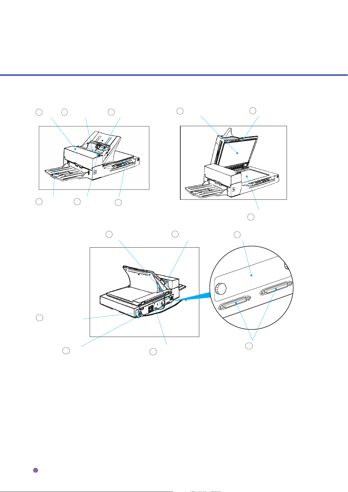
Units
7
1
ADF
2
Paper weight
(hidden)
3
ADF paper chute
Document holding pad
8
Document cover
6
Stacker
16
Power switch
5
15
Power inlet
ADF lever
4
Oparator panel
10
IMP connector
11
14
EXT connector
INT connector
9
12
Third party slot
13
Interface connector
Document bed
1-2
Page 12

o
N
Function
1
Automatic al l y feed s do cume nt s t o t he re adi n g pos i t i on.
2
Presses the documents loaded on the ADF paper chute.
3
Holds the documents to be fed by the ADF.
Displays the status of the scanner. Also displays buttons that enable the
4
operator to change settings in Feed mode, Manual Feed mode, and Setup
mode.
5
Opens/closes ADF to enable the removal of jammed documents.
6
Stacks the read documents.
7
Presses the document to the Document bed.
8
Closes over and keeps in place the document to be read.
9
Holds the document to be read. Also called Flatbed (FB).
DESCRIPTION
10
Connects to an option.
11
Connects to the EXT connector.
12
A Fujitsu Video Interface Option Board is install ed.
13
Connects to the host system with interface cables.
14
Connects to the INT connector.
15
Connects to an AC power outlet with the power cable.
16
Turns the power On or Off.
1-3
Page 13
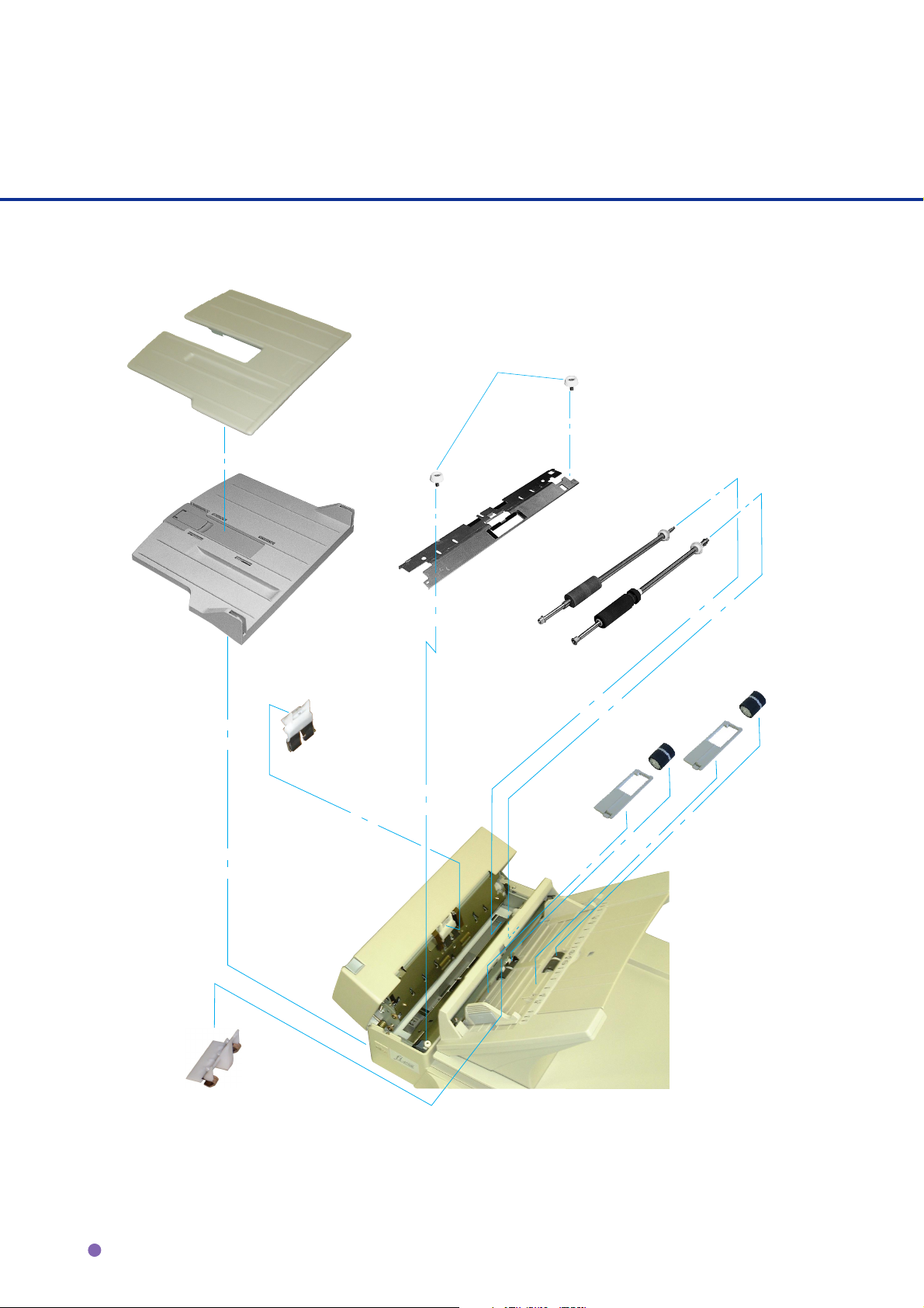
Assemblies
Adjustment
stacker
Thumb screw
Guide A
ASY
Pick roller 2
Stacker
Pad ASY
Pick roller 1
Roller
cover
Chute
roller
Chute
roller
Roller
cover
1-4
Gate ASY
Page 14
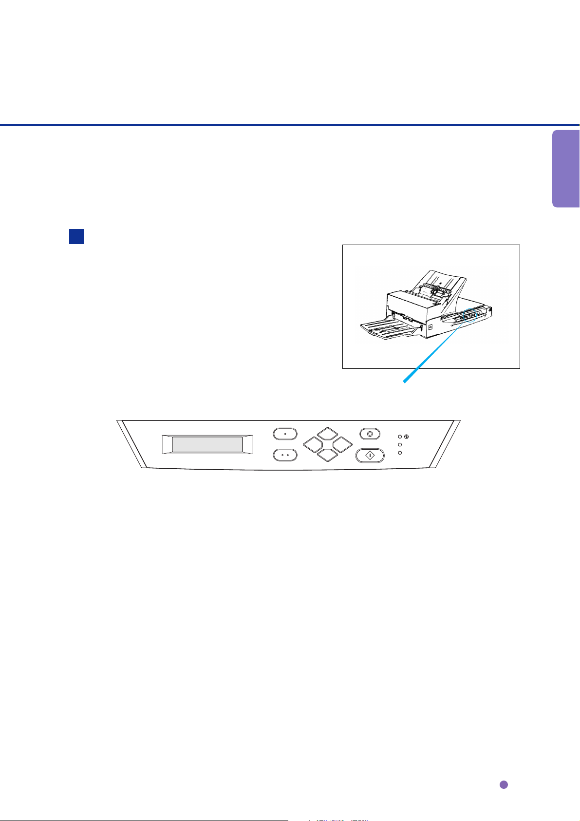
Operator panel
The Operator panel is located on the
upper right hand side of the scanner.
The panel consists of an LCD (16
characters x 2 lines), LEDs, and
buttons.
Arrangement
DESCRIPTION
Exit
Enter
Previous
Next
Operator panel
Stop
Send To/
Start
Read
Check
1-5
Page 15
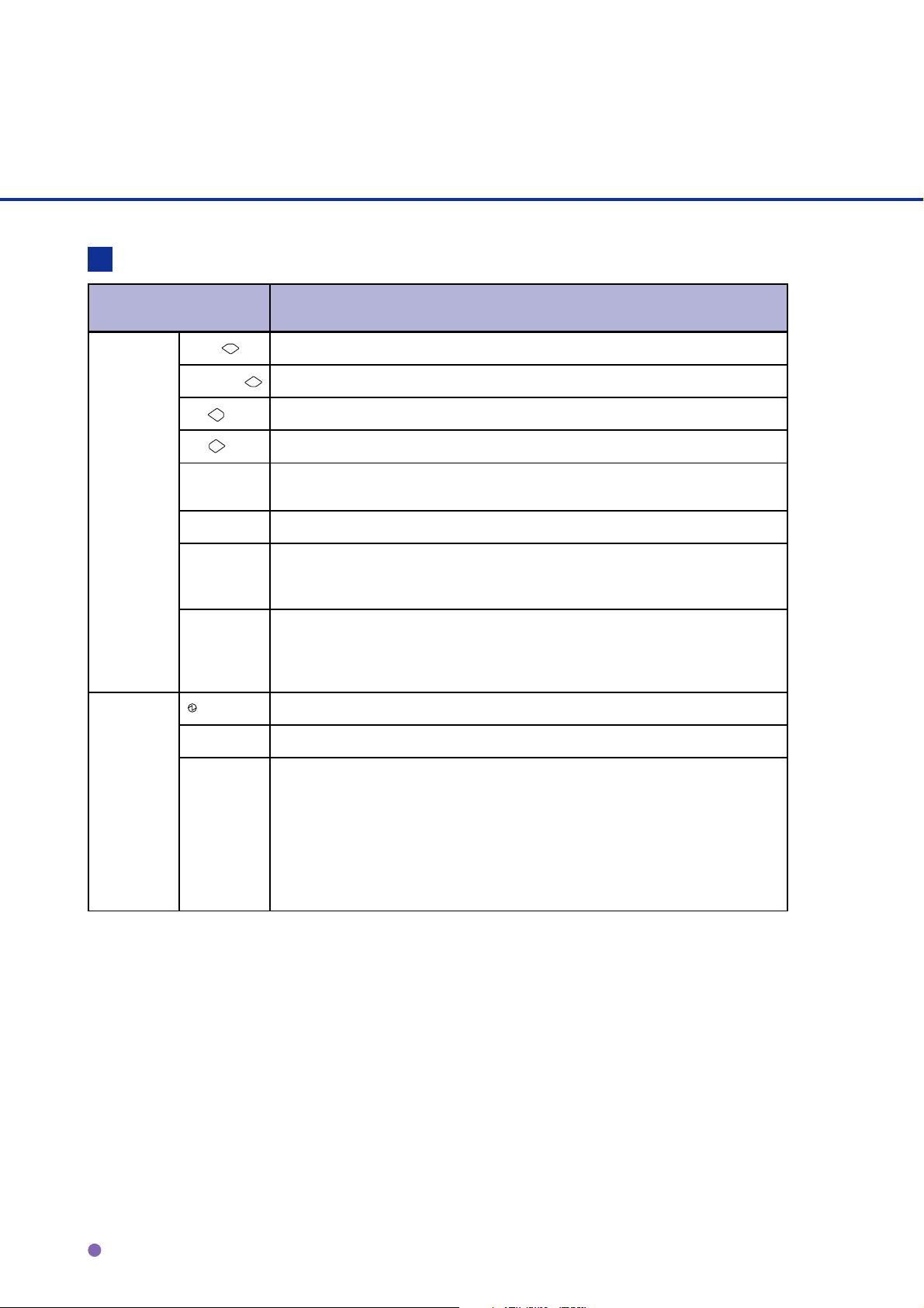
Button/LED Function
Name of the button and
LED
Button Next
Previous
Exit When you are entering settings on the Operat or panel, pressing this button
Enter
Send To
Start
Stop When the Check LED lights, pressing this button releases the error status
LED
Read
Function
Displays the next LCD screen.
Displays the previous LCD screen.
Moves the cursor (blinking part) to the left
Moves the cursor (blinking part) to the right
returns you immediately to the Scanner Ready screen.
Enters the parameter currently selected by the cursor.
Starts the reading. while Manual start mode is set or the Read lamp lights
when the video interface option is used. Some application software packages
might use this button.
(turns off Check and returns to the Scanner Ready screen). Stops the reading
while reading when the video interface option is used. Also turns off the Check
lamp.
Indicates the scanner is ON.
Indicates the scanner is reading or ready to read.
Check If lit, indicates an alarm occurred. Pressing the Stop button turns the Check
lamp off.
If it blinks at one second intervals, this indicates a jam or double feed has been
detected. If the problem is jammed paper, removing paper turns off the Check
lamp. If the problem is double feed, pressing the Stop button turns off the
Check lamp.
If it blinks at four second intervals, t his indicates cleaning the ADF is
necessary.
1-6
Page 16

Counter Display
The scanner is provided with a counter
Paper counter
display.
Abrasion counter
Counter Function
Paper counter When the
button is pressed
When the
button is pressed
Abrasion counter Abrasion counter counts the accumulat ed number of t he scanned s heet . This
counter incr ements at every 10 sheet s. This counter i s usef ul to check the
cleaning cycl e or parts replacement cyc le. How to reset i s described in
Chapter 6.
The paper counter counts t he number of scanned sheet s
from the start of reading unti l Paper Empty or unt i l an
error is detected. The counter is aut omatically reset at
the start of reading. The counter is used for checking
the number of sheets scanned at one time.
This counter i ncr ements each t ime a document is
scanned. The counter is not initialized until the power is
turned of f. The counter can be used, for example, for
checking the number of sheets that have been scanned
in one day.
DESCRIPTION
NOTE
When the counter value is 0, no number is displayed.
1-7
Page 17
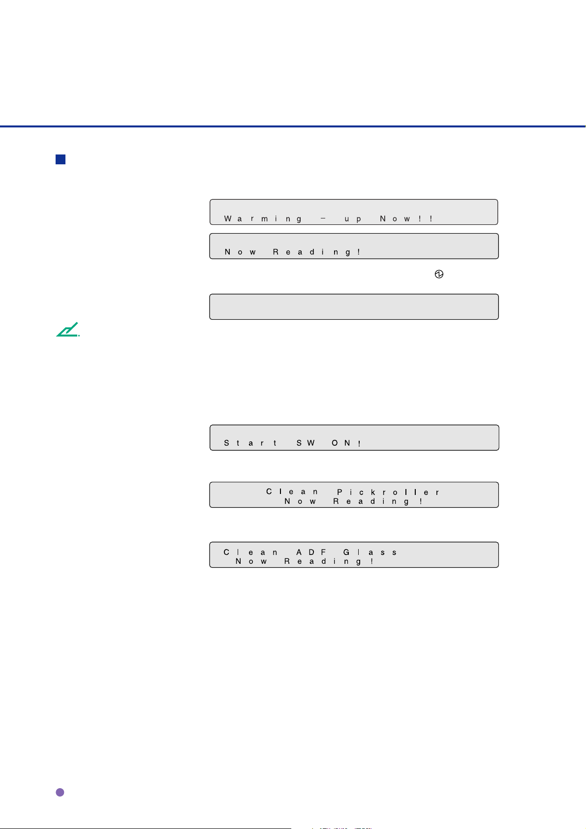
Panel Display
Operation status
The operation status is indicated by the following messages:
<Power-on>
<Reading>
<Low Power Mode> When the Scanner Display turns Off and the power indicator
remains “On”, the scanner is in the Low Power Mode.
NOTE
One of the following will wake up the scanner:
• Pressing any button.
• Setting the paper on the ADF.
• Sending a command from the host computer.
<Waiting for Start> The scanner displays the following screen when waiting for the
Start button to be pressed:
(Only When the Video Interface
Option is installed.)
<Cleaning request> When the Pick roller cleaning is necessary, the scanner displays
the following on the upper line:
When the ADF glass cleaning is necessary, the scanner displays
the following on the LCD:
Clean the Pick roller or the ADF glass in accordance with the
instructions given in chapter 2, Cleaning the ADF, and chapter 3,
Pick Roller.
1-8
Page 18

Temporary error
<Hopper empty>
<Jam>
<ADF cover open>
<Double feed error>
DESCRIPTION
This message is displayed if there is no more paper on the ADF
paper chute during a read operation in ADF mode. Fill the ADF
paper chute with paper. To enable the read operation, press the
stop button.
This message is displayed if a document is jammed in the ADF.
See Chapter 4 for removing jammed ducuments.
This message is displayed if the ADF is not closed completely.
Close the ADF completely, and enable the read operation.
This message is displayed when the ADF detects a Double feed
error. Check the document and re-scan it.
1-9
Page 19

Alarm
One of the following messages is displayed if an error occurs in the scanner. If one of the following
error messages is displayed, turn the power Off and then On again. If the same message is
displayed, contact your service representative.
<Optical alarm front>
<Optical alarm back>
<FB mechanism alarm>
NOTE
When the total number of sheets scanned by the ADF is less than 100, the message above and the
message below are displayed alternately. Remove the bracket (Shipping Lock) that holds the carrier
in place.
1-10
Page 20

<Motor fuse alarm>
<Lamp fuse alarm>
<Image transfer alarm>
<Memory alarm>
<EEPROM alarm>
<FAN alarm>
<SCSI fuse alarm>
DESCRIPTION
NOTE
When this message is displayed, turn Off system power and then turn it On again. Alternatively,
replace the current cable with one recommended by the manufacturer of the SCSI board. When the
cause of the alarm has been corrected, the scanner automatically resumes operation once power is
turned On again.
1-11
Page 21

CHAPTER
2
CLEANING
This chapter describes cleaning supplies, areas that require cleaning, and procedures for cleaning the ADF and the flatbed.
Cleaning Supplies and Areas Requiring Cleaning
Cleaning the ADF
Cleaning the Flatbed
2-1
Page 22

Cleaning Supplies and Areas Requiring Cleaning
Document cover
Document
holding pad
Document
bed
Supplies
Type No.
Cleaning paper Contact your Every 5,000 sheets
dealer or
Cleaner F2 distributor • Plastic rollers (*2) 1 bottle
Cleaner F1 or • PAD assembly 1 bottle.
Isopropyl alcohol Every 5,000 sheets Apply Cleaner F1
• Pick roller/Feed rollers/ to cloth.
Glass/Sheet guide
Every 5,000 sheets
Cotton swab
Dry cloth
*1 If the display on the operator panel shows “Please clean Pick-roller”, then clean it regardless of the frequencies
recommended here.
CAUTION
*2 Do not clean the rubber rollers with cleaner F2.
NOTE
When the following paper types are used, it may be necessary to clean more frequently:
• Paper with a smooth surface, such as coated paper.
• Paper almost entirely covered with printing.
• Paper with special chemical coatings, such as carbonless paper.
• Paper including a great quantity of calcium.
• When reading a great many documents written with a pencil.
*3 Refer to the Abrasion counter on the Operator panel to estimate when the next cleaning is necessary.
RemarksSupplies Frequencies (*1)(*3)
Apply Cleaner F2
to cotton swab.
2-2
Page 23

Areas Requiring Cleaning
Area
Flatbed
ADF
ADF
Name
Document holding pad
Document bed
Pad
Glass/Sheet guide
Pick roller
Plastic rollers
Feed rollers
Paper weight rollers
Chute rollers
Document holding
pad
Cleaning paper
with Cleaner F1
Document bed
Dry cloth
with Cleaner F1
Feed rollersPad
Plastic rollers
Cotton swab
with Cleaner F1 or F2
CLEANING
Paper weight rollers
(hidden)
Plastic rollers
Sheet guide
(white part)
Glass
Pick rollers
Chute rollers
2-3
Page 24

Cleaning the ADF
pow-on
Cleaning the ADF with cleaning paper
Pull the ADF lever to open the
1
ADF.
Apply cleaner F1 to a new piece
2
of cleaning paper.
Place the cleaning paper on the
3
ADF so that the edge of the short
side touches the Plastic roller.
Close the ADF and turn the
4
power on to start the cleaning.
Turn the power off.
5
Repeat steps 1 through 5.
6
Cleaning paper
Cleaning
paper
Plastic
rollers
2-4
Page 25

Cleaning the ADF with a Dry cloth or a Cloth with Cleaner F1
Pull the ADF lever to open the
1
ADF.
Use a dry cloth or a cloth
2
moistened with Cleaner F1 to
softly remove dirt and dust as
follows.
CLEANING
Pad assembly :
Wipe the pad in a downward direction
(as indicated by the arrow). Be careful
not to catch the spring for the Pick roller
when wiping.
Glass:
Wipe the glass lightly.
NOTE
If the glass is dirty, the image may include black
vertical stripes.
Pad assembly
Glass
2-5
Page 26

Pick roller:
Wipe the roller.
Pick roller
Be careful not to damage the surface of
the roller and the mylar strip above the
Pick roller.
○○○○○○○○○○○○○○○○○○○○○○○○○○○○○○○○○○○○○○○○○○○○○○○○○○○○○○○○○○○
Feed rollers and Plastic rollers:
Wipe the rollers.
Be careful not to damage the surface of
the rollers.
Feed rollers
Plastic rollers
Plastic rollers
2-6
Page 27

Sheet guide (white part):
Sheet guide (white part)
Wipe the sheet guide.
NOTE
If the Sheet guide is dirty, the front image may show
vertical stripes.
○○○○○○○○○○○○○○○○○○○○○○○○○○○○○○○○○○○○○○○○○○○○○○○○○○○○○○○○○○○
Close the ADF to lock the ADF
3
lever.
CLEANING
2-7
Page 28

Cleaning the Plastic rollers with Cleaner F2
Pull the ADF lever to open the
1
ADF.
Moisten a cotton swab with
2
Cleaner F2.
Wipe the Plastic roller surfaces.
3
CAUTION
Don’t wipe the Pick Rollers with a cotton swab using
cleaner F2.
Wipe the Plastic roller surface
4
with a clean, dry cloth. Allow it to
dry.
Plastic rollers
Plastic rollers
2-8
Page 29

Cleaning the Paper Weight Rollers with Cleaner F1 or F2
Moisten a cotton swab or Dry
1
cloth with F1 or F2 Cleaner.
While holding the Paper Weight,
2
wipe the small Plastic rollers at
the tip of the Paper Weight.
Wipe the small Plastic rollers and
3
the Paper Weight with a clean,
dry cloth to dry them.
Cleaning Chute Rollers with Cleaner F1
Use a dry cloth or a cloth moistened
with Cleaner F1 and wipe rollers softly.
CLEANING
Chute rollers
2-9
Page 30

Cleaning the Flatbed
Cleaning the Flatbed with a Cloth and Cleaner F1
Document cover
Document
holding pad
Document bed
NOTE
Window or glass cleaner can be used instead of cleaner F1. However, do not use organic solvents.
○○○○○○○○○○○○○○○○○○○○○○○○○○○○○○○○○○○○○○○○○○○○○○○○○○○○○○○○○○○
Open the Document cover.
1
Apply Cleaner F1 to a clean
2
cloth.
Wipe the Document holding pad
3
and the Document bed.
Allow them to dry.
4
NOTE
Be sure to prevent liquid from seeping through the opening between the Document bed and the plastic cover.
2-10
Page 31

CHAPTER
3
REPLACEMENT OF PARTS
This chapter describes how to replace the pad assembly, the pick
roller, and the chute roller.
Pad Assembly
Pick Roller
Chute Roller
3-1
Page 32

Pad Assembly
Pad ASY (PA03951-0193)
ADF lever
○○○○○○○○○○○○○○○○○○○○○○○○○○○○○○○○○○○○○○○○○○○○○○○○○○○○○○○○○○○
The life span of the pad assembly is about 100,000
sheets or one year. Use the Abrasion counter on
the Operator panel to estimate when the Pad
assembly needs replacement. The life span may be
decreased by as much as half when carbonless
paper is read frequently.
Turn off the power before replacing the Pad
Assembly.
○○○○○○○○○○○○○○○○○○○○○○○○○○○○○○○○○○○○○○○○○○○○○○○○○○○○○○○○○○○
NOTE
WARNING
Pull the ADF lever to open the
1
ADF.
3-2
Page 33

Slide the Pad Assembly to the left
2
and pull it towards you. Then,
being careful not to hook the
spring for the Pad, remove the
Pad Assembly.
NOTE
Hold both ends of the Pad assembly as shown in the
right photo.
CAUTION
Don’t hold the sensor arm with the Pad assembly.
○○○○○○○○○○○○○○○○○○○○○○○○○○○○○○○○○○○○○○○○○○○○○○○○○○○○○○○○○○○
Attach the Pad Assembly to the
3
Pad assembly
ADF in the reverse sequence of
step 2.
NOTE
Fit the Pad assembly pin into the larger hole, then
slide it to the right until it stops.
○○○○○○○○○○○○○○○○○○○○○○○○○○○○○○○○○○○○○○○○○○○○○○○○○○○○○○○○○○○
Close the ADF.
4
OF PARTS
REPLACEMENT
3-3
Page 34

Pick Roller
Pick rollers (PA03951-0194)
(Two rollers are included)
NOTE
The life span of the Pick roller is about 200, 000 sheets or one year.
Use the Abrasion counter on the operator panel to estimate when the Pick roller needs replacement.
The life span may be decreased by as much as half when carbonless sheets are frequently read.
WARNING
Turn off the power before replacing the Pick Rollers.
○○○○○○○○○○○○○○○○○○○○○○○○○○○○○○○○○○○○○○○○○○○○○○○○○○○○○○○○○○○
Pull the ADF lever to open the
1
ADF.
Remove the two Thumb
2
screws.
NOTE
Use a Phillips screwdriver if they are tight.
Thumb screws
3-4
Page 35

With both hands, lift up Guide A
3
and disengage its tip from the
right hole. Then lift the right side
of the cover and remove it.
○○○○○○○○○○○○○○○○○○○○○○○○○○○○○○○○○○○○○○○○○○○○○○○○○○○○○○○○○○○
To remove the Pick rollers, turn
4
the stopper counter-clockwise.
Pick roller 2
Stopper
Pick roller 1
OF PARTS
REPLACEMENT
Position for Replacement
3-5
Page 36

To remove the Pick roller 1, move
5
it to the left and then lift it.
○○○○○○○○○○○○○○○○○○○○○○○○○○○○○○○○○○○○○○○○○○○○○○○○○○○○○○○○○○○
Immediately after removing the
6
Pick roller 1, remove the Pick
roller 2 in the same way.
3-6
Page 37

To attach the new Pick rollers,
7
place Pick roller 1 from the right
side above the bearing for Pick
roller 1.
NOTE
Pick roller 1 has a groove in its rubber.
Put the shaft of Pick roller 1 into
the bearing. Then, slide Pick
roller 1 toward the right side.
OF PARTS
REPLACEMENT
NOTE
Make sure that the shaft is securely fixed to the bearings.
3-7
Page 38

Attach Pick roller 2, in the same
8
way as Pick roller 1 as shown in
step
Then slide the Pick roller 2 toward
right side.
.
7
NOTE
Make sure that the shaft is securely fixed to the bearings.
3-8
Page 39

Turn the stopper clockwise to
9
secure the Pick rollers.
Stopper
OF PARTS
REPLACEMENT
Operating Position
3-9
Page 40

Guide A
10
○○○○○○○○○○○○○○○○○○○○○○○○○○○○○○○○○○○○○○○○○○○○○○○○○○○○○○○○○○○
11
12
Attach Guide A in the reverse
sequence of step 3 and align the
screw hole. See the graphic on
page 1-4.
Tighten the thumb screws.
Close the ADF unit.
Thumb screws
3-10
Page 41

Chute Roller
Chute rollers (PA03951-0196)
(Two rollers are included)
NOTE
The life span of the Chute roller is about 1,000,000 sheets or 2.5 years.
The life span may be decreased by as much as half when carbonless sheets are frequently read.
Replace the two Chute rollers at the same time.
WARNING
Turn off the power before replacing the Chute rollers.
OF PARTS
REPLACEMENT
○○○○○○○○○○○○○○○○○○○○○○○○○○○○○○○○○○○○○○○○○○○○○○○○○○○○○○○○○○○
Lift and hold the Paper weight.
1
○○○○○○○○○○○○○○○○○○○○○○○○○○○○○○○○○○○○○○○○○○○○○○○○○○○○○○○○○○○
Move the Gate assembly
2
leftwards and pull towards you.
3-11
Page 42

While pushing the claw of the
3
Roller cover, remove the Roller
cover.
○○○○○○○○○○○○○○○○○○○○○○○○○○○○○○○○○○○○○○○○○○○○○○○○○○○○○○○○○○○
While pushing the claw of the
4
Chute roller, move the Chute
roller leftwards to remove it.
○○○○○○○○○○○○○○○○○○○○○○○○○○○○○○○○○○○○○○○○○○○○○○○○○○○○○○○○○○○
Put the new Chute roller on the
5
shaft and move it rightwards.
NOTE
When moving the Chute roller rightwards, gently turn the roller until the claw of the Chute roller is locked.
3-12
Page 43

Mount the Roller cover.
6
NOTE
Make sure that the claw of the Roller cover is firmly locked.
○○○○○○○○○○○○○○○○○○○○○○○○○○○○○○○○○○○○○○○○○○○○○○○○○○○○○○○○○○○
Mount the Gate assembly in the
7
reverse sequence of step 2.
OF PARTS
REPLACEMENT
NOTE
Insert the pin of the Gate assembly into the large hole and move the assembly leftwards until it stops.
NOTE
If the Gate assembly is not securely mounted, the Paper weight cannot go down during read operation and then
paper jams occur.
○○○○○○○○○○○○○○○○○○○○○○○○○○○○○○○○○○○○○○○○○○○○○○○○○○○○○○○○○○○
Release the Paper weight.
8
3-13
Page 44

While pushing the claw of the
9
Roller cover, remove the Roller
cover.
○○○○○○○○○○○○○○○○○○○○○○○○○○○○○○○○○○○○○○○○○○○○○○○○○○○○○○○○○○○
10
○○○○○○○○○○○○○○○○○○○○○○○○○○○○○○○○○○○○○○○○○○○○○○○○○○○○○○○○○○○
11
While pushing the claw of the
Chute roller, move the Chute
roller leftwards to remove it.
Put the new Chute roller on the
shaft and move it rightwards.
NOTE
When moving the Chute roller rightwards, gently turn the roller until the claw of the Chute roller is locked.
3-14
Page 45

12
Make sure that the claw of the Roller cover is firmly locked.
Guidelines on replacing the Chute roller are as follows:
Mount the Roller cover.
NOTE
NOTE
• The life span of the Chute roller is about 1,000,000 sheets or 2.5 years. We recommend the life span that
comes first.
• If documents are not fed into the ADF frequently and it cannot be solved instantly by cleaning the Chute roller.
ADF paper
ADF side
The chute roller slips
so that the document
cannot be fed into
the ADF.
chute side
OF PARTS
REPLACEMENT
A pair of Chute rollers come with your scanner at purchase. Replace the two Chute rollers at the same time.
The life span may be decreased depending on types or printing conditions of your documents.
3-15
Page 46

3-16
Page 47

CHAPTER
4
TROUBLESHOOTING
This chapter describes how to clear paper jams and run initial checks.
It also contains a Problem Checklist that should be completed before
you call a service representative.
Clearing Paper Jams
Initial Checks
Problem Checklist
4-1
Page 48

Clearing Paper Jams
ADF paper chute
ADF
ADF lever
○○○○○○○○○○○○○○○○○○○○○○○○○○○○○○○○○○○○○○○○○○○○○○○○○○○○○○○○○○○
Remove all the documents from
1
the ADF paper chute.
Pull the ADF lever to open the
2
ADF.
Lift and hold the paper weight.
3
Remove the jammed
4
document(s).
NOTES
- Inspect the paper and the paper path. Make sure no staples, paper clips or other materials caused the jam. All
staples and paper clips should be removed from all documents bofore scanning.
- Be careful not to pull the spring for the Pad while removing a jammed document.
Close the ADF so that the ADF
5
lever locks.
4-2
Page 49

Initial Checks
If a problem occurs, check the following items before contacting the manufacturer’s authorized service
center.
Symptom 1
The power does not go On.
Is the power cable
connected correctly?
YES
Is the power switch on?
YES
Contact the manufacturer’s authorized
service center.
(No light)
NO
Connect the power cable
correctly.
NO
Press the power switch.
TROUBLESHOOTING
4-3
Page 50

Symptom 2
The operator panel turns “Off”.
Power “On”
Has it been a long time
since the scanner was last
used?
NO
Did the scanner enter this
state quickly?
NO
Did you load the paper on
the ADF?
NO
Have 10 seconds passed
since the PC instructed a
scan?
YES
Press any button on the
operator panel to wake up the
system.
YES
Extend the time for entering
"Low Power Mode" in Set Up
Mode.
YES
Load the paper again, or
press any button on the
operator panel.
YES
Wait for at least 10 seconds.
YES
Contact the manufacturer’s authorized
service center.
4-4
Page 51

Symptom 3
Read operation does not start.
Is the Shipping Lock
placed in an operating
position?
YES
Are the documents loaded
correctly on the ADF paper
chute?
YES
Is the ADF completely
closed?
YES
Is the interface cable
connected correctly?
NO
NO
NO
NO
Place the Shipping Lock
correctly.
(See the Operator’s Guide,
p. 2-4)
Insert the documents into the
slot.
Completely close the ADF.
TROUBLESHOOTING
Connect the interface cable
correctly.
YES
4-5
Page 52

Is the scanner the last
device of the SCSI chain?
YES
NO
The termination should be
turned off via the front panel.
Is the SCSI ID set
correctly?
YES
Is the baud rate of the
system 4800 bps?
(When you use the Fujitsu
video interface board.)
YES
CHECK
Is the CHECK indicator lit?
Is an Alarm displayed?
NO
Contact the manufacturer’s authorized
service center.
NO
NO
YES
Set the SCSI ID correctly.
Use the operator panel to
change the ID.
Contact the manufacturer’s
authorized service center to
set the correct baud rate.
Refer to Symptom 6.
(See p. 4-9)
4-6
Page 53

Symptom 4
Pictures and photographs are not read correctly.
Is the “Photo” mode
selected?
YES
Is halftone or dither
processing selected?
YES
Are the Document bed,
Document holding pad,
glass, and sheet guides
clean?
YES
NO
NO
NO
Select the “Photo” mode
(White level following “Off”)
through the scanner setting
menu in the software.
Select the halftone or
dithering mode from the host
computer.
Clean the dirty parts.
(See p. 2-5, p. 2-7, p. 2-10)
TROUBLESHOOTING
Contact the manufacturer’s authorized
service center.
4-7
Page 54

Symptom 5
Characters and lines are not read correctly.
NO
3mm
Is the “Line Art” mode
selected?
YES
Is there any printed text on
the first 3mm of the
document?
NO
Are the Document bed,
Document holding pad,
glass, and sheet guides
clean?
YES
YES
NO
Select the “Line Art” mode
from the host computer.
Select the “Photo” mode
(White level following “Off”)
via software.
Clean the dirty parts.
(See p. 2-5, p. 2-7, p. 2-10)
Contact the manufacturer’s authorized
service center.
4-8
Page 55

Symptom 6
Images are distorted or unclear.
missing
Are the Document bed,
Document holding pad,
glass and sheet guides
clean?
YES
During rear read operation
with the ADF, is the top of
the ADF being pressed or
is there anything heavy on
it?
NO
Is the scanner on an even
and flat surface or are any
rubber feet of the scanner
missing?
YES
NO
YES
NO
Clean the dirty parts.
(See p. 2-5, p. 2-7, p. 2-10)
Do not press the top of the
ADF or put anything heavy on
it.
Place the scanner on a flat,
even surface or attach the
rubber feet.
TROUBLESHOOTING
Contact the manufacturer’s authorized
service center.
4-9
Page 56

Symptom 7
Images have vertical lines.
Did you scan the
document using the
Flatbed?
Are the lines white?
NO
Are the lines black?
NO
Contact the manufacturer’s authorized
service center.
YES
Contact the manufacturer’s
authorized service center.
YES
Clean the ADF Glass.
4-10
Page 57

Symptom 8
The Check indicator is on.
CHECK
Is the Shipping Lock
placed in operating
position?
YES
Turn off the power once
and then try to turn on the
CHECK
power again. Is the
CHECK lamp still on? Or is
an Alarm displayed?
YES
Contact the manufacturer’s authorized
service center.
NO
Place the Shipping Lock
correctly.
(See Operator’s Guide.)
TROUBLESHOOTING
4-11
Page 58

Symptom 9
“Please clean Pick-roller” is displayed.
YES
Is the Pick roller dirty?
NO
Do documents meet
specification described in
the Operator’s Guide?
YES
Is the Pad assembly dirty
or worn out?
NO
Clean the Pick roller.
(See p. 2-6)
NO
Flatten the curl or use the
Flatbed to read the document.
YES
Clean or replace the Pad
assembly.
(See p. 3-2, p. 3-3)
Contact the manufacturer’s authorized
service center.
4-12
Page 59

NOTES
NOTES
• Remove paper clips and staples. Flatten the staple holes.
• Read the following types of documents using the Flatbed:
- Paper with clips or staples.
- Paper with wet ink.
- Paper of uneven thickness (for example, envelopes).
- Paper with large rumples or curls.
- Paper with folds or tears.
- Tracing paper.
- Coated paper.
- Carbon paper.
- Paper smaller than A6 size or larger than A3.
- Materials other than paper (for example, cloth, sheet metal, or OHP film).
- Photographic paper.
- Paper with perforations on its sides.
- Non-rectangular paper.
- Very thin paper.
• The leading edge of all documents fed by the ADF should be straightened so the curl of the paper
meets the specifications below:
Less than
More than 30mm
3mm
Top of the paper
• Do not mix documents of different widths.
Feed direction
Read surface
Less than
5mm
More than 30mm
Feed direction
Read surface
Top of the paper
TROUBLESHOOTING
4-13
Page 60

Symptom 10
Paper double feed occurs frequently.
Does the condition of the
documents meet the
requirements described in
the Operator’s Guide?
YES
When double feed
detection is ON, are all the
documents of the same
length?
YES
Are the documents fanned
before being loaded on the
ADF paper chute?
YES
NO
Flatten the curl or use the
Flatbed to read the
documents.
NO
Set double feed detection to
“Off”. (See the Operator’s
Guide)
NO
Fan the documents before
loading, or reduce the batch
size.
4-14
Have the documents
recently been printed by
copier or laser printer?
NO
YES
Fan the stack 3 or 4 times to
remove the static charge
applied to the paper.
Page 61

Is the document stack less
than 0.32” (8mm) in
height?
YES
Is the Pad dirty?
NO
Is the Pad worn out?
NO
NO
Reduce the batch size of the
documents.
YES
Clean the Pad assembly.
(See p. 2-4)
YES
Replace the Pad assembly.
(See p. 3-2)
TROUBLESHOOTING
Contact the manufacturer’s authorized
service center.
4-15
Page 62

Symptom 11
Paper jam 1 or paper jam 2 occurs frequently.
Do the conditions of the
documents meet the
requirements described in
the Operator’s Guide?
YES
Have the documents been
fanned before loading them
on the ADF paper chute?
YES
Is the Gate assembly
installed correctly?
YES
NO
Flatten the curl or use the
Flatbed to read the
documents.
NO
Fan the documents before
loading, or reduce the batch
size.
NO
Install it correctly.
(See p. 3-5)
4-16
Is the Pad assembly
installed correctly?
YES
NO
Install it correctly.
(See p. 3-2)
Page 63

Is the Chute roller dirty?
NO
Is the Chute roller worn
out?
NO
Is the Pick roller dirty?
NO
YES
Clean the Chute roller.
(See p. 2-9)
YES
Replace the Chute roller.
(See p. 3-11)
YES
Clean the Pick roller.
(See p. 2-6)
TROUBLESHOOTING
Is the Pick roller worn out?
NO
Contact the manufacturer’s authorized
service center.
YES
Replace the Pick roller.
(See p. 3-4)
4-17
Page 64

Symptom 12
Paper jam 3 occurs frequently.
Does the condition of the
document meet the
requirements on page
4-13?
NO
Are there any foreign
particles in the ADF?
NO
Contact the manufacturer’s authorized
service center.
YES
Flatten the curl or use the
Flatbed to read the document.
YES
Clean the ADF (see p. 2-4) or
remove the foreign particles.
4-18
Page 65

Symptom 13
“Please clean ADF glass” is displayed.
Is the ADF glass dirty?
NO
Contact the manufacturer’s authorized
service center.
YES
Clean the ADF glass.
(See p. 2-5)
TROUBLESHOOTING
4-19
Page 66

Problem Checklist
Before contacting the manufacturer’s authorized service center, please fill in the following items.
General
Model
Part number
Serial number
Manufactured date
Revision
A
0
123456789
B
0
123456789
C
0123456789
Date of purchase
Symptoms
Persistent problem?
Serviced before (when and how)?
Error status
Transport error
Type of document.
What is your daily usage?
Date of last cleaning.
Date of the consumable replacement.
(Example) fi-4750L
(Example) CA02956-2371
(Example) 00002
(Example) 2001-3
The revision is printed on the label
located at the left corner of the back.
The revision is indicated by the double line.
This example shows the revision A2.
Image error
Interface controller model
Software/application name
Can you send the original and output of
sheet by facsimile or by mail?
4-20
Page 67

 Loading...