

Fujifilm X-M1 Service Manual
DIGITAL CAMERA
X-M1
SERVICE MANUAL
US/EE/EG/ME/RU/CH/JP-model
USE THE DESIGNATED AFTER-SALES PARTS AND THE DESIGNATED LEAD-FREE
THE COMPONENTS IDENTIFIED WITH THE MARK “
CAUTION
SOLDER WHEN PERFORMING REPAIRS. BECAUSE THIS PRODUCT COMPLIES WITH
RoHS LEAD-FREE. (Refer to page 3)
WARNING
AND THE PARTS LIST ARE CRITICAL FOR SAFETY.
” IN THE SCHEMATIC DIAGRAM
REPLACE THOSE COMPONENTS ONLY WITH THE COMPONENTS SPECIFIED IN THE
SCHEMATIC DIAGRAM AND THE PARTS LIST.
IF YOU USE PARTS NOT SPECIFIED, IT CAN RESULT IN A FIRE AND AN ELECTRICAL
SHOCK.
Ref.No.: ZM01086-107
Revised on 14 Aug 2014
Confidential: FUJIFILM Service Center Use Only
A
X-M1 Service Manual
SAFETY CHECK-OUT
During repair and safety checking, conduct the followings.
1. Check if there are unsoldered or poorly
soldered connections. Check the entire
board surface for solder splasher and
bridges.
2. Check the inter-board wiring to ensure that
no wires are "pinched" or contact highwattage resistors.
3. Look for unauthorized replaced parts,
particularly transistors that were installed in
a previous repair. Point this out to a
customer and recommend replacing with
authorized parts.
4. Look for parts which, though functioning,
signs of deterioration. Point this out to a
customer and recommend replacing with
new parts.
5. Check the B + voltage to see if it is the
correct value.
6. Check leakage current see if exposed parts
are insulated from power supply before
returning a camera to a customer.
7.
2.5A 125V
2.5A 125V
RISK OF FIREREPLACE FUSE
S MARKED
8.
CAUTION:
FOR PROTECTION
AGAINST FIRE HAZARD,
REPLACE ONLY WITH
SAME TYPE 2.5 AMPERES
125V/250V FUSE.
ATTENTION:
AFIN D'ASSURER UNE
PROTECTION
PERMANENTE CONTRE
LES RISQUES D'INCENDIE,
REMPLACER
UNIQUEMENT PAR UN
FUSIBLE DE MEME, TYPE
2.5 AMPERES, 125/250
VOLTS.
WARNING:
TO AVOID THE ELECTRIC
SHOCK, BE CAREFUL TO
TOUCH THE PARTS.
WARNING!
HIGH VOLTAGE
2
Confidential: FUJIFILM Service Center Use Only
X-M1 Service Manual
RoHS lead-free compliance
With the exception of parts and materials expressly excluded from the RoHS directive, all the internal con nections and
component parts and materials used in this product are lead-free compliant under the European RoHS directive (*1). Use the
specified parts and the specified lead-free solder when repairing.
*1: Definition of lead-free
A lead content ratio of 0.1 wt% or less in the applicable locations (solder, terminals, electronic components, etc.)
<Lead-free soldering>
When lead-free solder is used, soldering can be less working efficiency than when eutectic solder is used. When repairing,
use a specific lead-free solder, bearing in mind the difference between eutectic soldering and lead-free soldering.
Differences between lead-free and eutectic soldering
Melting point
Eutectic solder (Sn-Pb)
183°C 220°C
Lead-free solder
(Sn-Ag-Cu)
Remark
Soldering iron
temperature
Wetting
Surface
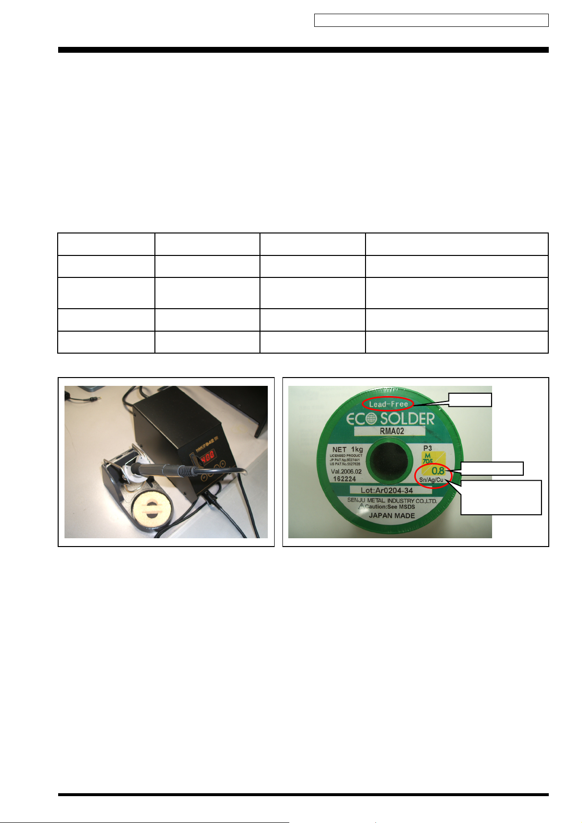
Example of recommended equipment and solder
Maintenance of soldering iron
Because of the high soldering iron temperature when lead-free soldering, Carbonization of the flux adhered to the tip of
the soldering iron proceeds faster than eutectic soldering.
(1) Always cover the tip of the soldering iron with solder when it is not used.
(2) If the tip becomes black by carbonization, wipe it gently with a paper towel soaked in alcohol so that the solder can
wet.
283°C 320°C
Good Poor
Gloss Matte
This should be determined by heat capacity
at a connecting portion and working
efficiency.
lead-free
Wire diameter
Solder type
(Displayed symbol)
SnAgCu
3

Confidential: FUJIFILM Service Center Use Only
X-M1 Service Manual
MEMO
4

Confidential: FUJIFILM Service Center Use Only
X-M1 Service Manual
CONTENTS
1. List of Jigs····································································································1-1
2. Disassembly ·································································································2-1
3. Adjustments ·································································································3-1
4. Inspection·····································································································4-1
5. Parts List······································································································5-1
5-1. Packing and Accessories·······································································5-1
5-2. Mechanical Block 1 ···············································································5-2
5-3. Mechanical Block 2 ···············································································5-3
5-4. Mechanical Block 3 ···············································································5-4
5-5. Electrical Parts ·····················································································5-5
6. Appendix······································································································6-1
5

Confidential: FUJIFILM Service Center Use Only
X-M1 Service Manual
MEMO
6

Confidential: FUJIFILM Service Center Use Only
1. List of Jigs X-M1 Service Manual
1. List of Jigs
1-1. Tool list
Parts No. Name Image Comment Remarks MUST/WANT
ZJ02083-100 SCREWDRIVER (+) 1.5X40L General repair MUST
ZJ02033-100 TORQUE DRIVER Used in torque management MUST
ZJ02070-100 VESSEL M160082 +BIT 0*82 Used in torque management MUST
ZJ00581-100 Discharger Discharge for FLASH UNIT MUST
ZJ01923-100 Grip press tool Type A General repair MUST
ZJ01924-100 Grip press tool Type B General repair MUST
ZJ01925-100 Grip press tool Type C General repair MUST
ZJ01926-100 Grip press tool Type D General repair MUST
ZJ01927-100 Grip press tool Type E General repair MUST
No Image
1-2. Auxiliary materials list
Parts No. Name Image Comment Remarks MUST/WANT
ZS00143-100 UL TAPE (BLACK) 19MM General repair UL TAPE (BLACK) 19MM MUST
No Image
ZS00144-100 UL TAPE (CLEAR) 9MM General repair UL TAPE (CLEAR) 9MM MUST
ZS00145-100 UL TAPE (CLEAR) 15MM General repair UL TAPE (CLEAR) 15MM MUST
ZS00169-100 UL TAPE CLEAR 30MM General repair UL TAPE CLEAR 30MM MUST
ZS00126-100 UL Bond SC950 General repair Bond MUST
ZS00175-100 KONISHI BOND SL220W General repair Bond MUST
ZS00135-200 CFD-409Z (LUBRICANT)
ZS00177-100 CRS-811 (GREASE)
ZS00185-100 HI-LUBE FG-600T General repair Lubricant MUST
ZJ02233-100 X-A1 PET SHEET General repair MUST
No Image
No Image
No Image
No Image
No Image
General repair Lubricant MUST
General repair Lubricant MUST
No Image
No Image
1-1
: Revised
Confidential: FUJIFILM Service Center Use Only
X-M1 Service Manual 1. List of Jigs
1-3. Adjustments
Parts No. Name Image Comment Remarks MUST/WANT
• DSC JIG Driver
ZJ00684-100
or
ZJ02197-100
DSC JIG Driver
FJIG DRIVER for Win7
----
USB JIG Driver
Use the ZJ00684-100 from
*1
web.
• FJIG DRIVER for Win7
Refer to the BULLETIN No.
2013-058.
*1
MUST
ZJ02216-100 X-M1 W PC Soft Ver.1.00
ZJ02217-100 X-M1 SD BOOT Soft
ZJ02219-100 MOUNT Data for X-M1
---- PTB450F Camera adjustment Pattern box MUST
FZ00330-200 AC Cable (For US/JP) Camera adjustment
FZ03982-100 AC Cable (For EG) Camera adjustment
FZ03983-100 AC Cable (For EU) Camera adjustment
ZJ00699-100 Filter LB145 Camera adjustment
ZJ00254-100 Gra y Chart (Reflective type) Flash adjustment
---- Micro USB cable General adjustment Commercially available item MUST
----
----
----
No Image
No Image
No Image
General adjustment New jig *1 MUST
Main PWB Initialize New jig *1 MUST
Mount Data Write New jig *1 MUST
Use it with PTB450F and a
*2
set
Use it with PTB450F and a
*2
set
Use it with PTB450F and a
*2
set
Common with the
8mmVTR/FinePix F700
Common with the
8mmVTR/FinePix F700
MUST
MUST
MUST
MUST
MUST
*1: Please download the software from Web server (https://cs-support-eid.fujifilm.co.jp).
*2: Select one the power cable suitable each country.
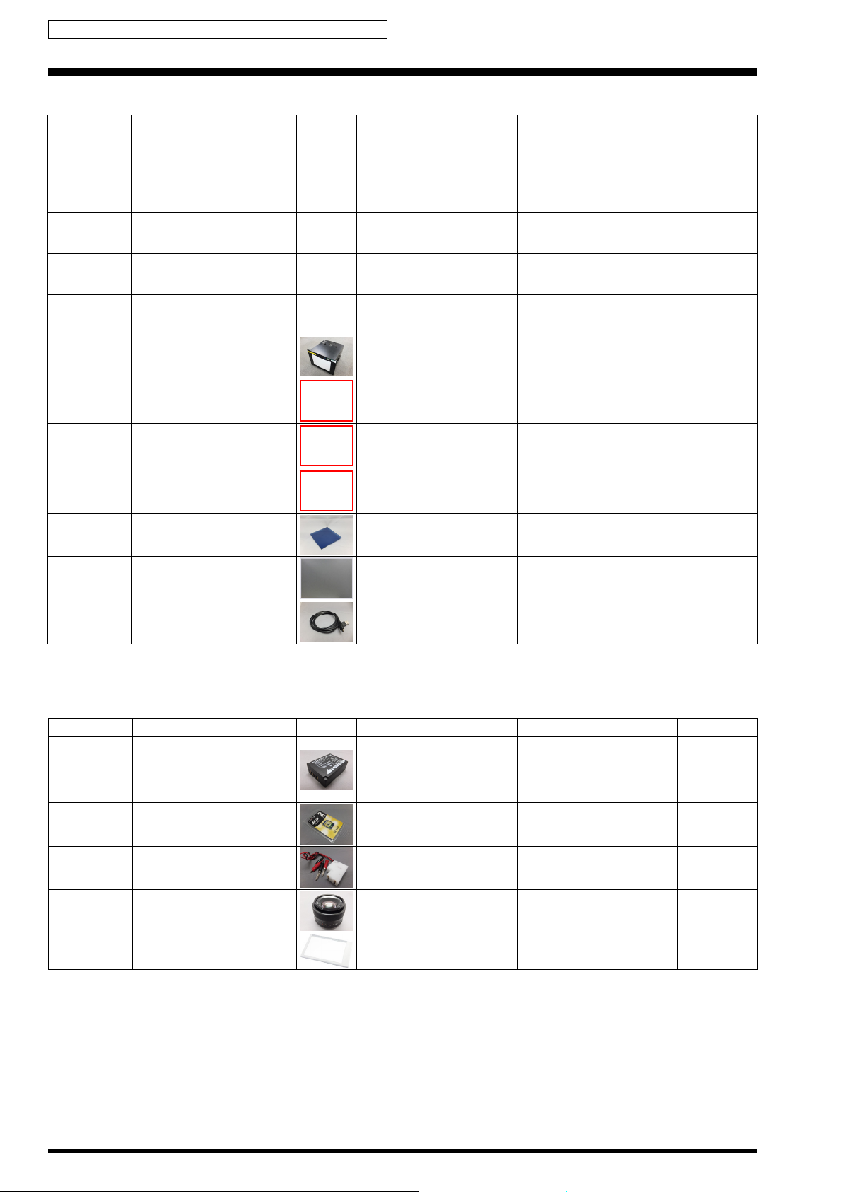
1-4. Adjustment/Inspection
Parts No. Name Image Comment Remarks MUST/WANT
FZ09206-100
or
FZ09206-200
or
FZ09206-300
ZPU0512-100 SD CARD ULTRA2 1GB
ZJ01936-100 NP-W126 Battery Jig
----
---- LED viewer
BATTERY PACK NP-W126J
BATTERY PACK NP-W126U
BATTERY PAC K NP-W126W
FUJINON LENS XF35mmF1.4
R
This is bundled to the product. MUST
Common with the X-Pro1 MUST
• CMOS Defect Correction
• CMOS Dust Inspection
To check inspection SD
recording
Products available from stock
(Use the latest version of the
firmware).
ST-N3 (FUJIFILM) W ANT
MUST
MUST
1-2
Confidential: FUJIFILM Service Center Use Only
1. List of Jigs X-M1 Service Manual
1-5. Inspection
Parts No. Name Image Comment Remarks MUST/WANT
---- Power supply
---- Digital voltmeter
Regulated power supply MUST
For general use MUST
---- Ammeter
ZJ01848-100 FxX100 Line Chart
ZS00172-100 Cleaning paper CMOS Cleaning WANT
ZJ02219-100
ZJ02218-100
X-M1 W Dust Inspection Soft
Ver.1.00
No Image
----
CMOS Dust Inspection New jig
For general use (able to
measure 1mA or less)
Common with the FinePix
X100
*1
*1: Please download the software from Web server (https://cs-support-eid.fujifilm.co.jp).
MUST
MUST
WANT
1-3
: Revised

Confidential: FUJIFILM Service Center Use Only
X-M1 Service Manual 1. List of Jigs
MEMO
1-4

Confidential: FUJIFILM Service Center Use Only
2. Disassembly X-M1 Service Manual
2. Disassembly
2-1. Removing the SHEET GRIP
(1) Peel off the SHEET GRIP R RIGHT2.
(2) Peel off the SHEET GRIP R RIGHT1.
(3) Peel off the SHEET GRIP R LEFT.
3
2
1
[Notes on Assembly]
• SHEET GRIP is not reusable.
• Refer to [2-9. Attaching the SHEET GRIP] for the affix the SHEET GRIP procedure.
2-1
Confidential: FUJIFILM Service Center Use Only
X-M1 Service Manual 2. Disassembly
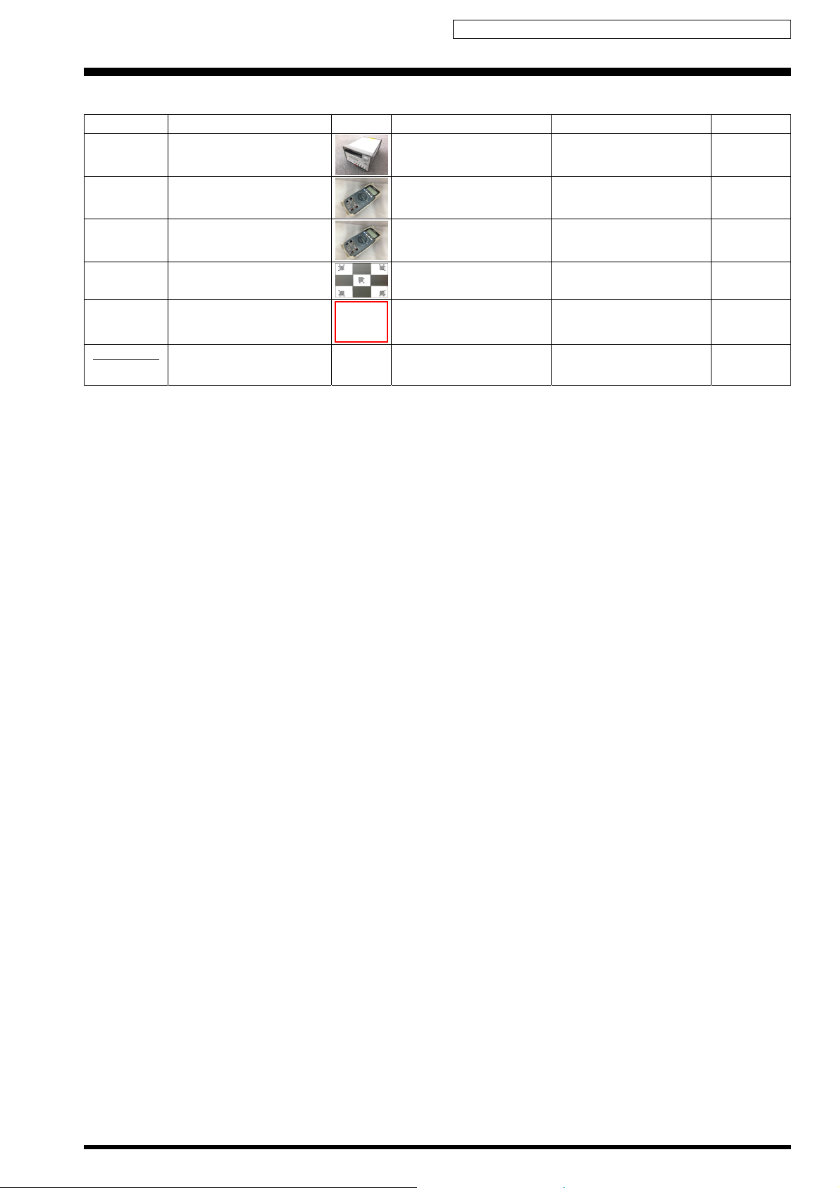
2-2. Removing the LCD
(1) Raise the LCD in the direction of the arrow.
(2) Peel off the SHEET INSULATE MAIN.
1
2
[Notes]
If TAPE INSULATE CENTER is affixed, peel it off.
[Notes on Assembly]
SHEET INSULATE MAIN is not reusable.
[Affixing position for the SHEET INSULATE MAIN]
Affix the SHEET INSULATE MAIN on the DSCAMERA
BASE as shown in the figure.
2-2
Confidential: FUJIFILM Service Center Use Only
2. Disassembly X-M1 Service Manual
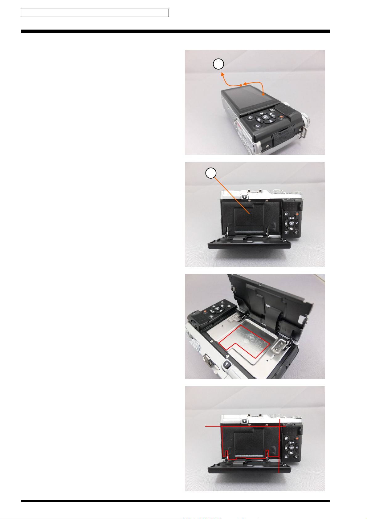
(3) Remove the Hooks, and remove the HOLDER LCD FPC in the direction of the arrow.
3
Hooks
(4) Remove the 4 screws (MSGM1.7X2.5B).
(5) Remove the WINDOW LCD ASSY in the direction of the arrow.
(6) Raise the LCD in the direction of the arrow.
4
5
4
6
2-3
Confidential: FUJIFILM Service Center Use Only
X-M1 Service Manual 2. Disassembly
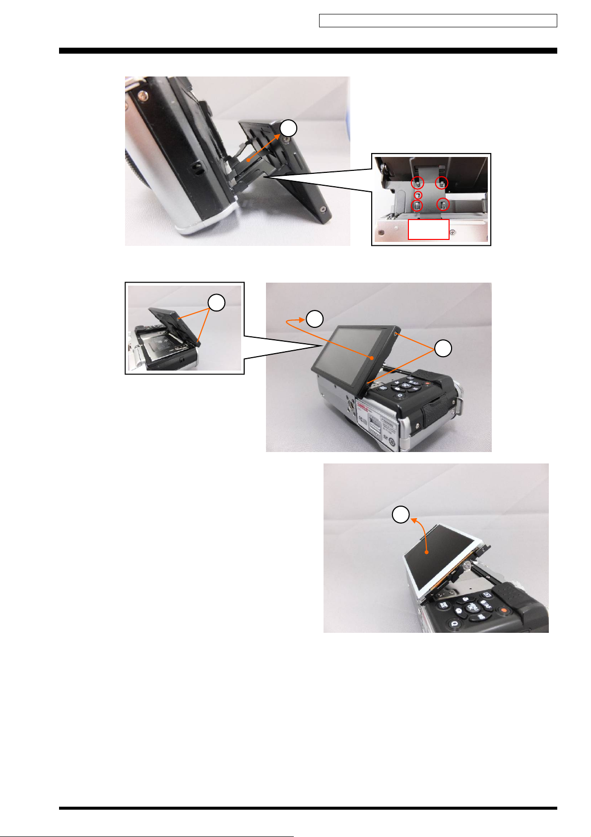
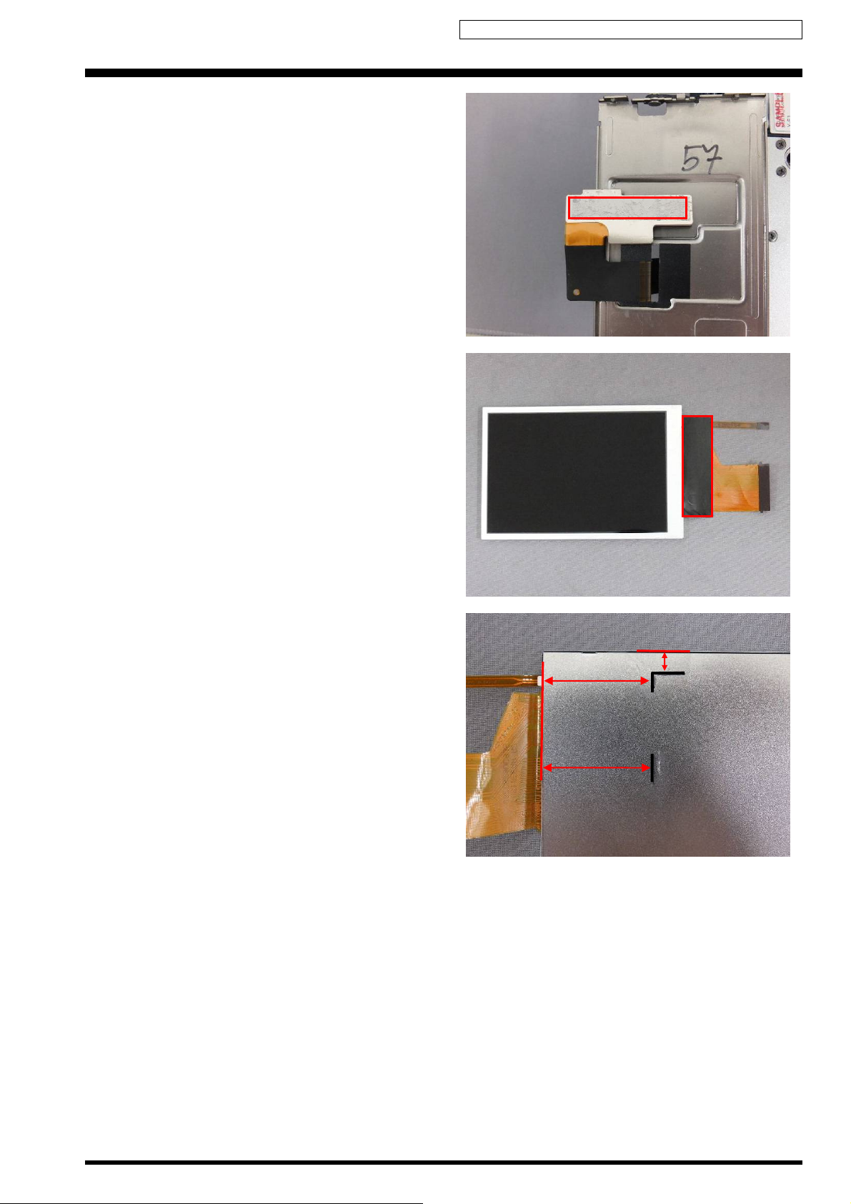
(6) Peel off the UL TAPE (30X37mm).
(7) Peel off the SHEET FPC LCD 1.
[Notes on Assembly]
UL TAPE (30X37mm) and SHEET FPC LCD 1 are not
reusable.
[Affixing position for the UL TAPE (30X37mm)]
Affix the UL TAPE (30X37mm) on the TILT_ASSY as shown
in the figure.
UL TAPE (CLEAR): ZS00169-100 (Width: 30mm)
7
6
[Affixing position for the SHEET FPC LCD 1]
Affix the SHEET FPC LCD 1 on the TILT_ASSY as shown in
the figure.
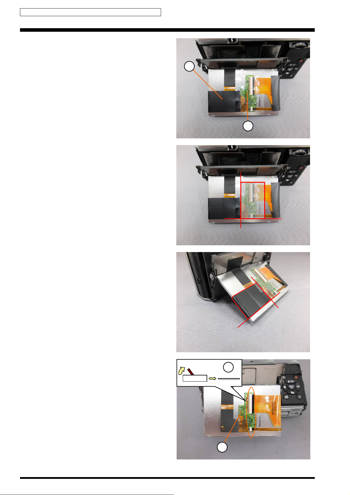
(8) Unlock the connector and remove the FPC.
(9) Peel off the TILT_ASSY and remove the LCD.
8
FPC
9
2-4
Confidential: FUJIFILM Service Center Use Only
2. Disassembly X-M1 Service Manual
[Notes on Assembly]
TAPE FPC LCD is not reusable.
[Affixing position for the TAPE FPC LCD]
Affix the TAPE FPC LCD on the TILT_ASSY as shown in the
figure.
[Precaution when replacing LCD]
1. SHEET FPC LCD 2 is not reusable.
[Affixing position for the SHEET FPC LCD 2]
Affix the SHEET FPC LCD 2 on the LCD as shown in the
figure.
2. Mark the lines as shown in the picture for the position of
the TILT_ASSY.
[Assembly]
Assemble procedure is reverse of the disassembly
procedure.
24mm
24mm
5mm
2-5
Confidential: FUJIFILM Service Center Use Only
X-M1 Service Manual 2. Disassembly
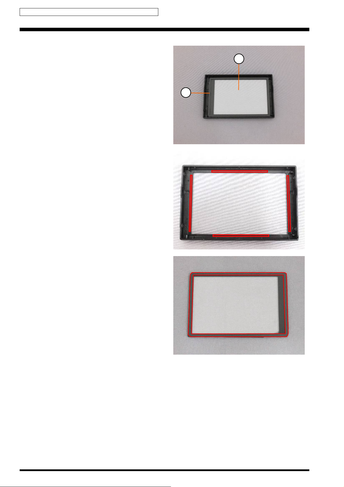
2-2-1. Disassembling the WINDOW LCD ASSY
(1) Remove the WINDOW LCD.
(2) Peel off the CUSHION LCD.
1
2
[Notes on Assembly]
TAPE WINDOW LCD and CUSHION LCD are not
reusable.
[Affixing position for the SHEET FPC LCD 2]
Affix the SHEET FPC LCD 2 on the CASE LCD F as shown
in the figure.
[Affixing position for the CUSHION LCD]
Affix the CUSHION LCD on the WINDOW LCD as shown in
the figure.
[Assembly]
Assemble procedure is reverse of the disassembly
procedure.
2-6
Confidential: FUJIFILM Service Center Use Only
2. Disassembly X-M1 Service Manual
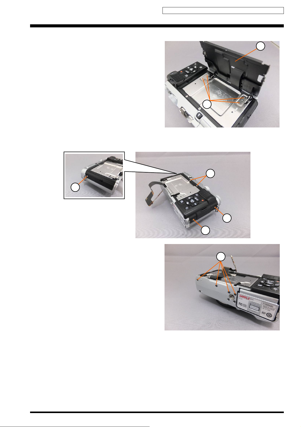
2-3. Removing the CONST REAR
(1) Remove the 4 screws (MSGM1.7X2.5).
(2) Remove the UNIT HINGE LCD.
(3) Remove the 2 screws (MS2M1.7X4.0B).
(4) Remove the screw (MS2M1.7X2.5).
(5) Remove the 2 screws (MS2M1.7X3.5).
2
1
5
(6) Remove the 4 screws (MSGM1.7X2.5B).
3
5
4
6
2-7
Confidential: FUJIFILM Service Center Use Only
X-M1 Service Manual 2. Disassembly
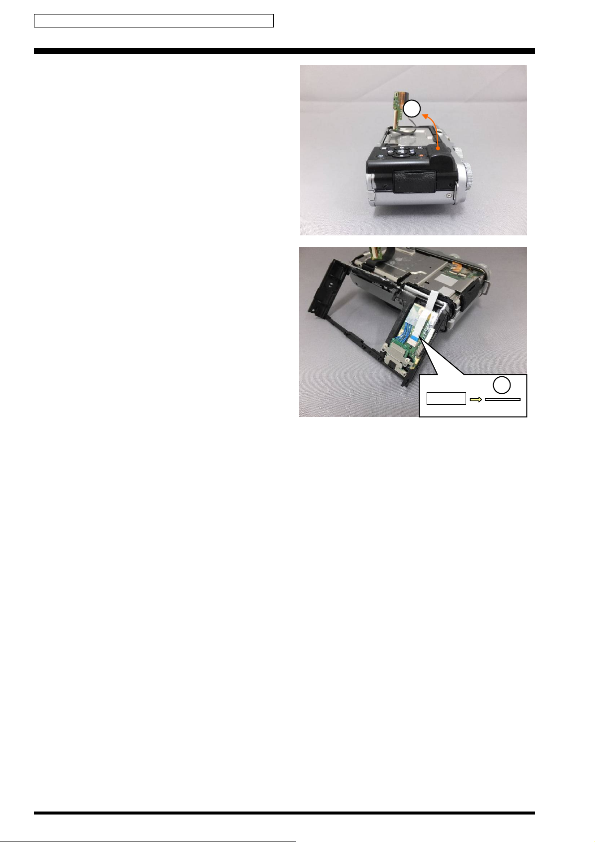
(7) Remove the CONST REAR in the direction of the arrow.
7
(8) Remove the REAR_FFC.
[Assembly]
Assemble procedure is reverse of the disassembly
procedure.
8
FFC
2-8
Confidential: FUJIFILM Service Center Use Only
2. Disassembly X-M1 Service Manual
2-4. Removing the FRAME MAIN
(1) Remove the SPEAKER.
(2) Remove the 3 screws (MSGM1.7X2.5).
(3) Remove the FRAME MAIN in the direction of the arrow.
3
1
[Notes on Assembly]
TAPE SPK is not reusable.
[Affixing position for the TAPE SPK]
Affix the TAPE SPK on the SPEAKER as shown in the
figure.
2
2
(4) Remove the COVER HINGE.
4
2-9
Confidential: FUJIFILM Service Center Use Only
X-M1 Service Manual 2. Disassembly
[Precaution when replacing FRAME MAIN]
UL TAPE (15X30mm), CUSHION SPEAKER, UL TAPE (6X13mm), UL TAPE (15X13mm) and UL TAPE (9X15mm) are
not reusable.
[Affixing position for the UL TAPE (15X30mm)]
Affix the UL TAPE (15X30mm) on the FRAME MAIN as shown in the figure.
UL TAPE (CLEAR): ZS00145-100 (Width: 15mm)
Back
[Affixing position for the CUSHION SPEAKER]
Affix the CUSHION SPEAKER on the FRAME MAIN as shown in the figure.
CUSHION SPEAKER
[Affixing position for the UL TAPE (6X13mm)]
Affix the UL TAPE (6X13mm) on the FRAME MAIN as shown in the figure.
UL TAPE (CLEAR): ZS00144-100 (Width: 9mm)
Back
2-10
Confidential: FUJIFILM Service Center Use Only
2. Disassembly X-M1 Service Manual
[Affixing position for the UL TAPE (6X13mm)]
Affix the TAPE (6X13mm) on the FRAME MAIN as shown in
the figure.
UL TAPE (CLEAR): ZS00144-100 (Width: 9mm)
[Affixing position for the UL TAPE (15X13mm)]
Affix the UL TAPE (15X13mm) on the FRAME MAIN as shown in the figure.
UL TAPE (CLEAR): ZS00145-100 (Width: 15mm)
Back
[Affixing position for the UL TAPE (9X15mm)]
Affix the UL TAPE (9X15mm) on the FRAME MAIN as shown in the figure.
UL TAPE (CLEAR): ZS00144-100 (Width: 9mm)
Back
[Assembly]
Assemble procedure is reverse of the disassembly procedure.
2-11
Confidential: FUJIFILM Service Center Use Only
X-M1 Service Manual 2. Disassembly
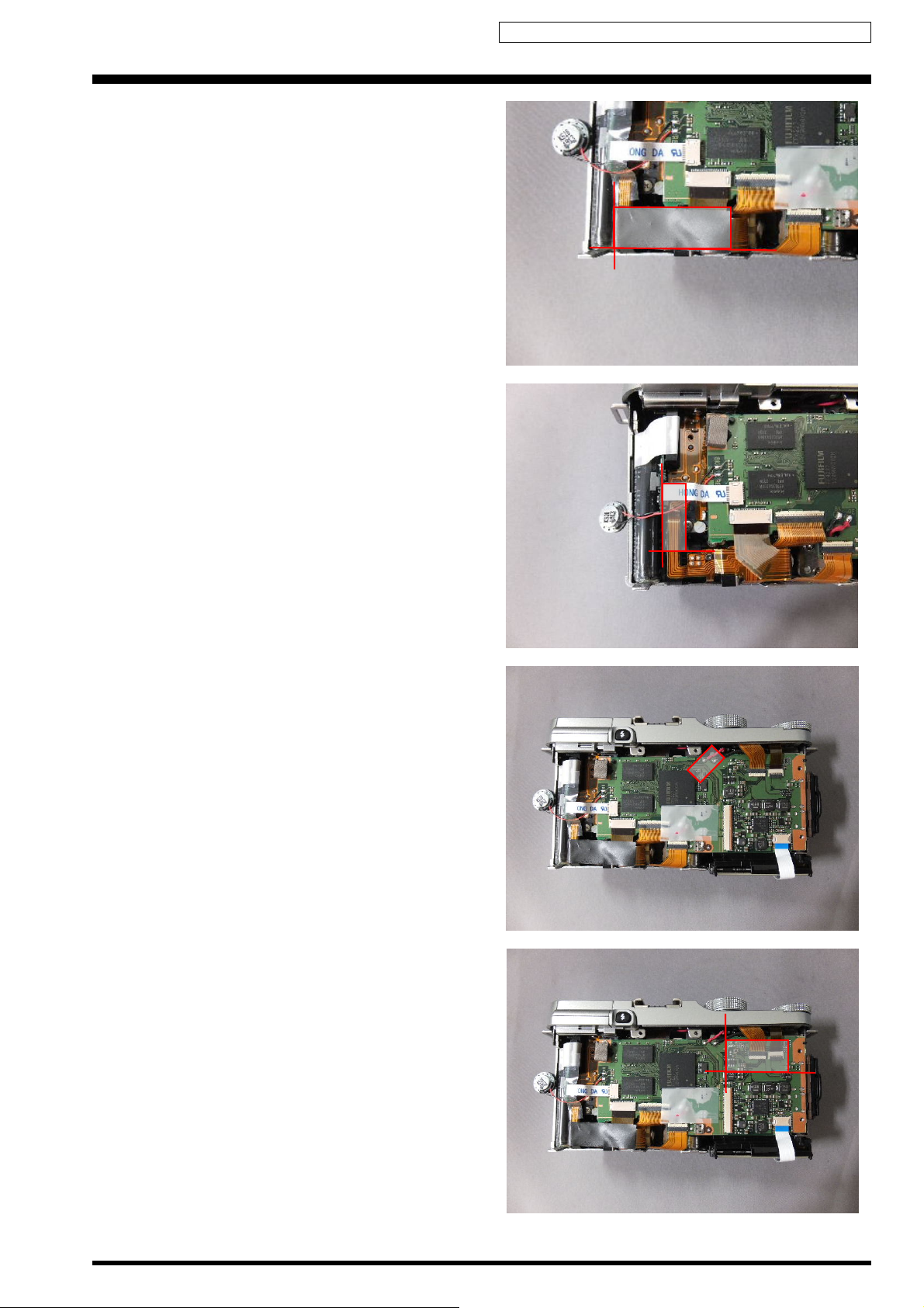
2-5. Removing the MAIN_ASSY
(1) Peel off the UL TAPE (15X30mm).
[Notes on Assembly]
UL TAPE (15X30mm) is not reusable.
[Affixing position for the UL TAPE (15X30mm)]
Affix the UL TAPE (15X30mm) on the MAIN_ASSY as
shown in the figure.
UL TAPE (CLEAR): ZS00169-100 (Width: 30mm)
1
(2) Unlock the connector and remove the TILT_ASSY.
(3) Peel off the SHEET FPC LCD 4.
(4) Peel off the UL TAPE (15X40mm).
(5) Peel off the UL TAPE (9X15mm).
(6) Peel off the UL TAPE (15X25mm).
(7) Peel off the UL TAPE (15X21mm).
2
FPC
5
6
4
2-12
7 3
Confidential: FUJIFILM Service Center Use Only
2. Disassembly X-M1 Service Manual
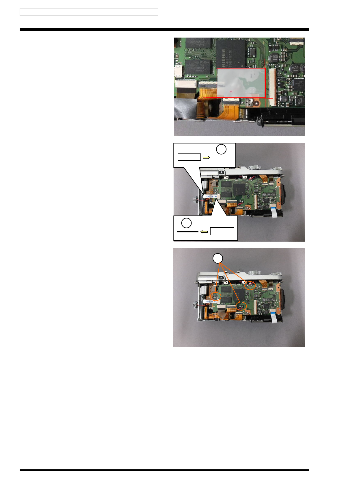
[Notes on Assembly]
SHEET FPC LCD 4, UL TAPE (15X40mm), UL TAPE
(9X15mm), UL TAPE (15X25mm) and UL TAPE
(15X21mm) are not reusable.
[Affixing position for the SHEET FPC LCD 4]
Affix the SHEET FPC LCD 4 on the CONST FRONT as
shown in the figure.
[Affixing position for the UL TAPE (15X40mm)]
Affix the UL TAPE (15X40mm) on the SPEAKER as shown
in the figure.
UL TAPE (CLEAR): ZS00145-100 (Width: 15mm)
[Affixing position for the UL TAPE (9X15mm)]
Affix the UL TAPE (9X15mm) on the MAIN_ASSY as shown
in the figure.
UL TAPE (CLEAR): ZS00144-100 (Width: 9mm)
[Affixing position for the UL TAPE (15X25mm)]
Affix the UL TAPE (15X25mm) on the MAIN_ASSY as
shown in the figure.
UL TAPE (CLEAR): ZS00145-100 (Width: 15mm)
2-13
Confidential: FUJIFILM Service Center Use Only
X-M1 Service Manual 2. Disassembly
[Affixing position for the UL TAPE (15X21mm)]
Affix the UL TAPE (15X21mm) on the MAIN_ASSY as
shown in the figure
UL TAPE (CLEAR): ZS00145-100 (Width: 15mm)
(8) Remove the FLASH_FFC.
8
FFC
(9) Remove 6 solders.
8
FFC
9
2-14
Confidential: FUJIFILM Service Center Use Only
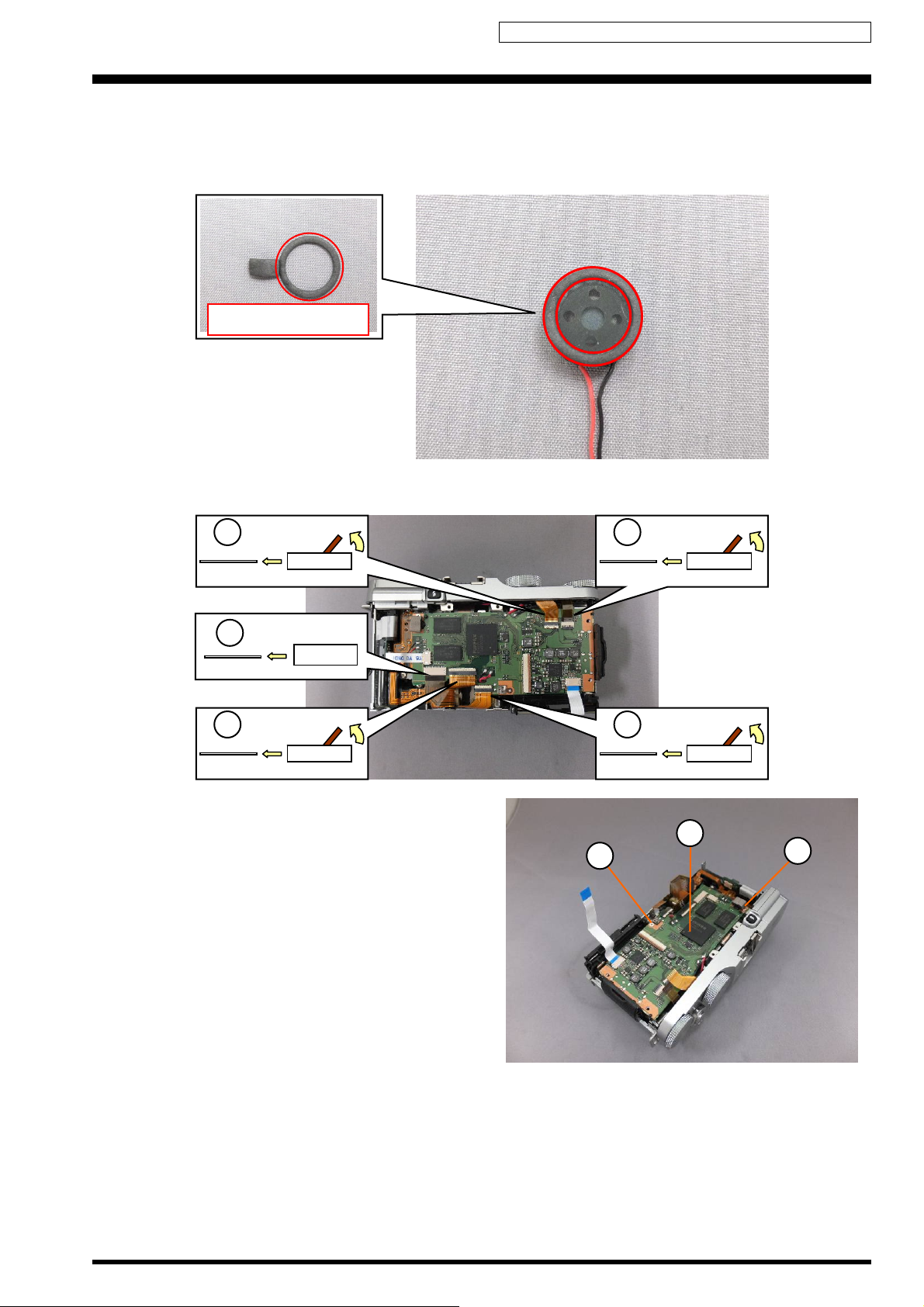
2. Disassembly X-M1 Service Manual
[Precaution when replacing SPEAKER]
CUSHION SPEAKER is not reusable.
[Affixing position for the CUSHION SPEAKER]
Affix the CUSHION SPEAKER on the SPEAKER as shown in the figure.
CUSHION SPEAKER
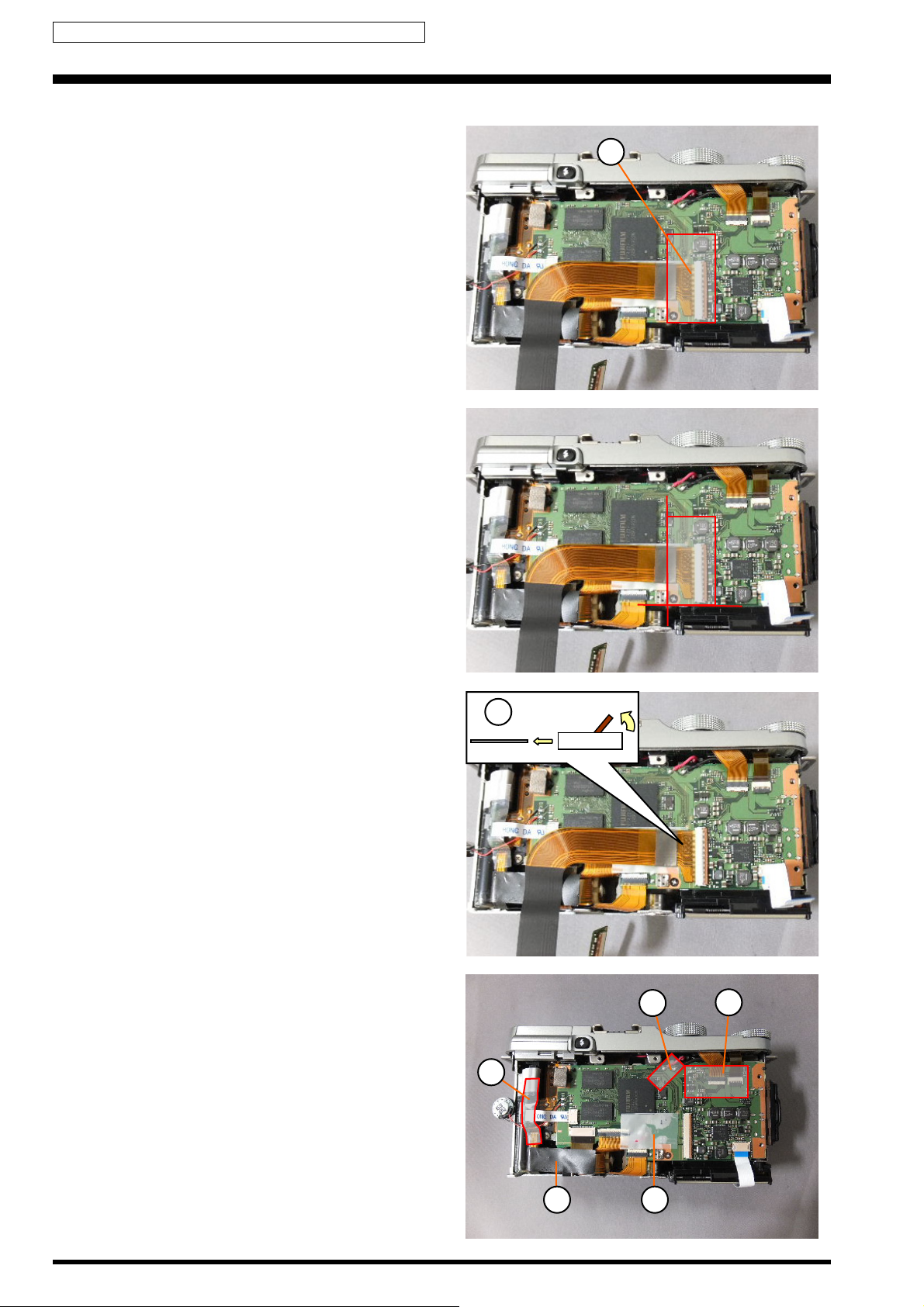
(10) Unlock the connector and remove the FPC.
(11) Remove the FPC.
10
FPC
11
FPC
10
FPC
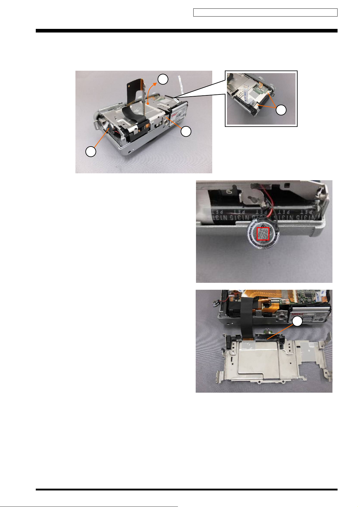
(12) Remove the screw (BT2M1.7X3.0).
(13) Remove the screw (MSGM1.7X2.5).
(14) Remove the MAIN_ASSY.
10
FPC
10
FPC
14
12
13
2-15
Confidential: FUJIFILM Service Center Use Only
X-M1 Service Manual 2. Disassembly
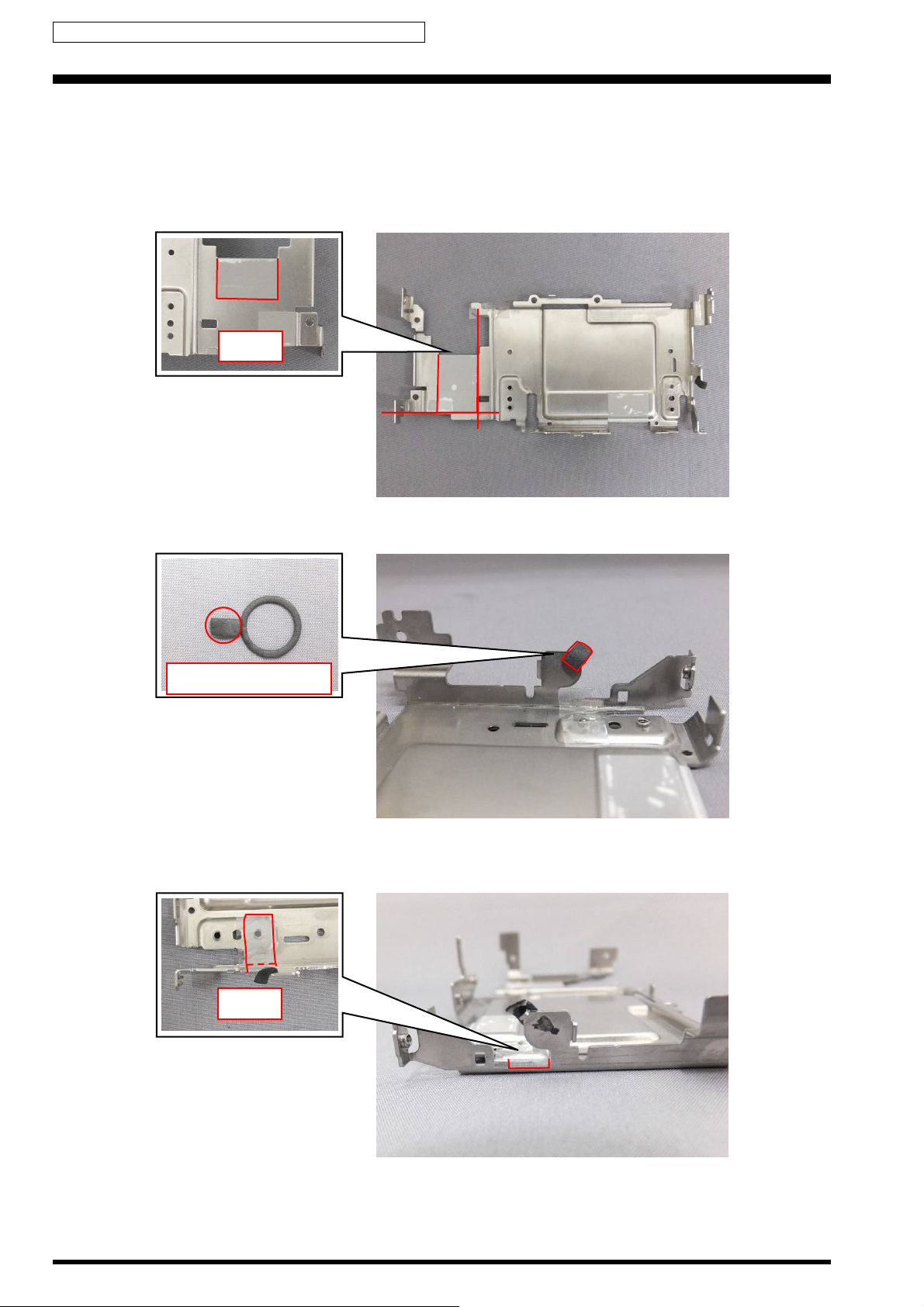
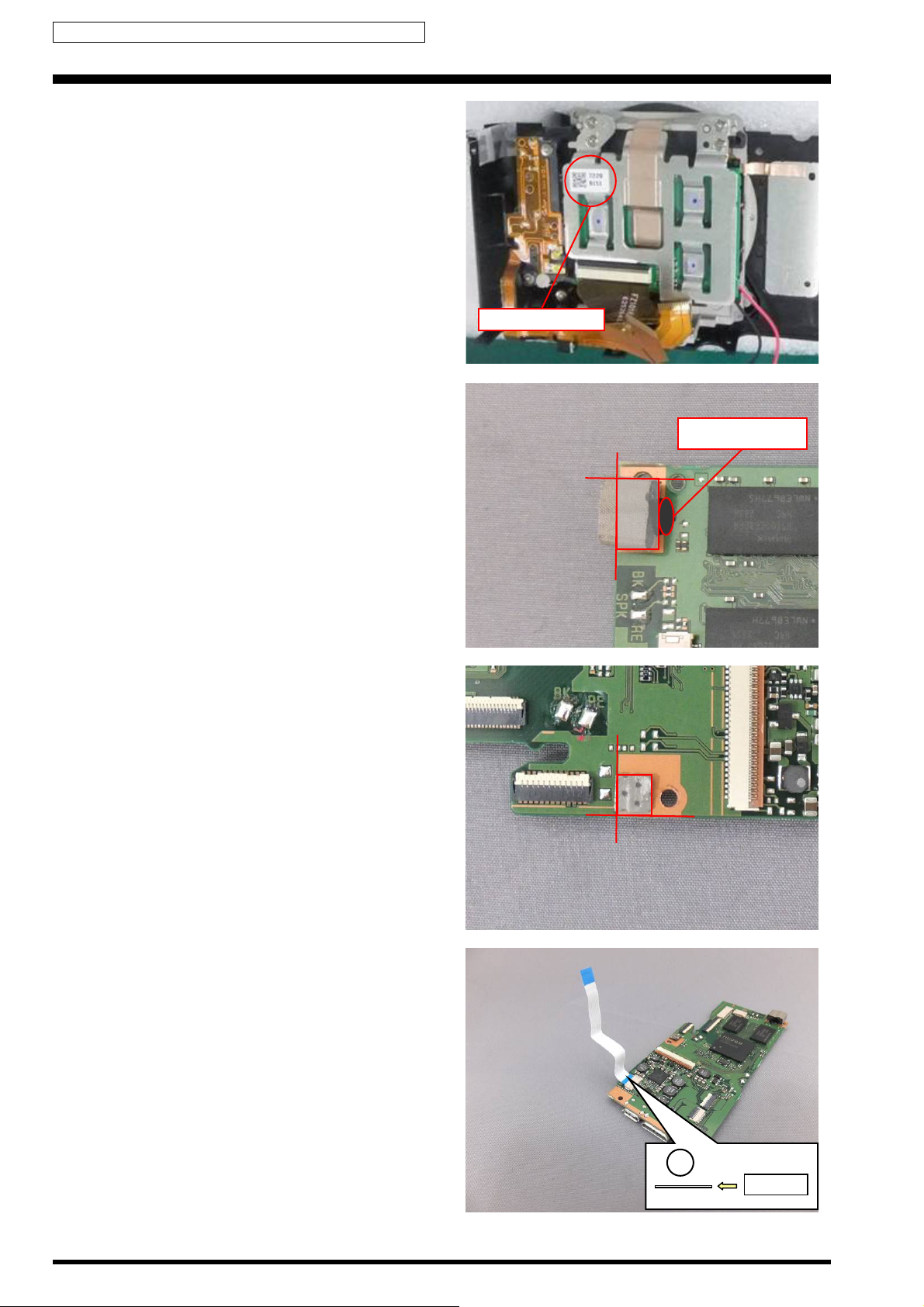
[Precaution when replacing MAIN_ASSY]
1. The MOUNT data (8 digits) is required for adjustment
by Mount Data Write.
To obtain the MOUNT data, refer to [3-5-1. Obtaining
the MOUNT data].
2. GASKET MAIN 1 and GASKET MAIN 2 are not
reusable.
[Affixing position for the GASKET MAIN 1]
Affix the GASKET MAIN 1 to MAIN_ASSY and apply the
bond as shown in the figure.
KONISHI BOND SL220W: ZS00175-100
MOUNT number
Bonding position
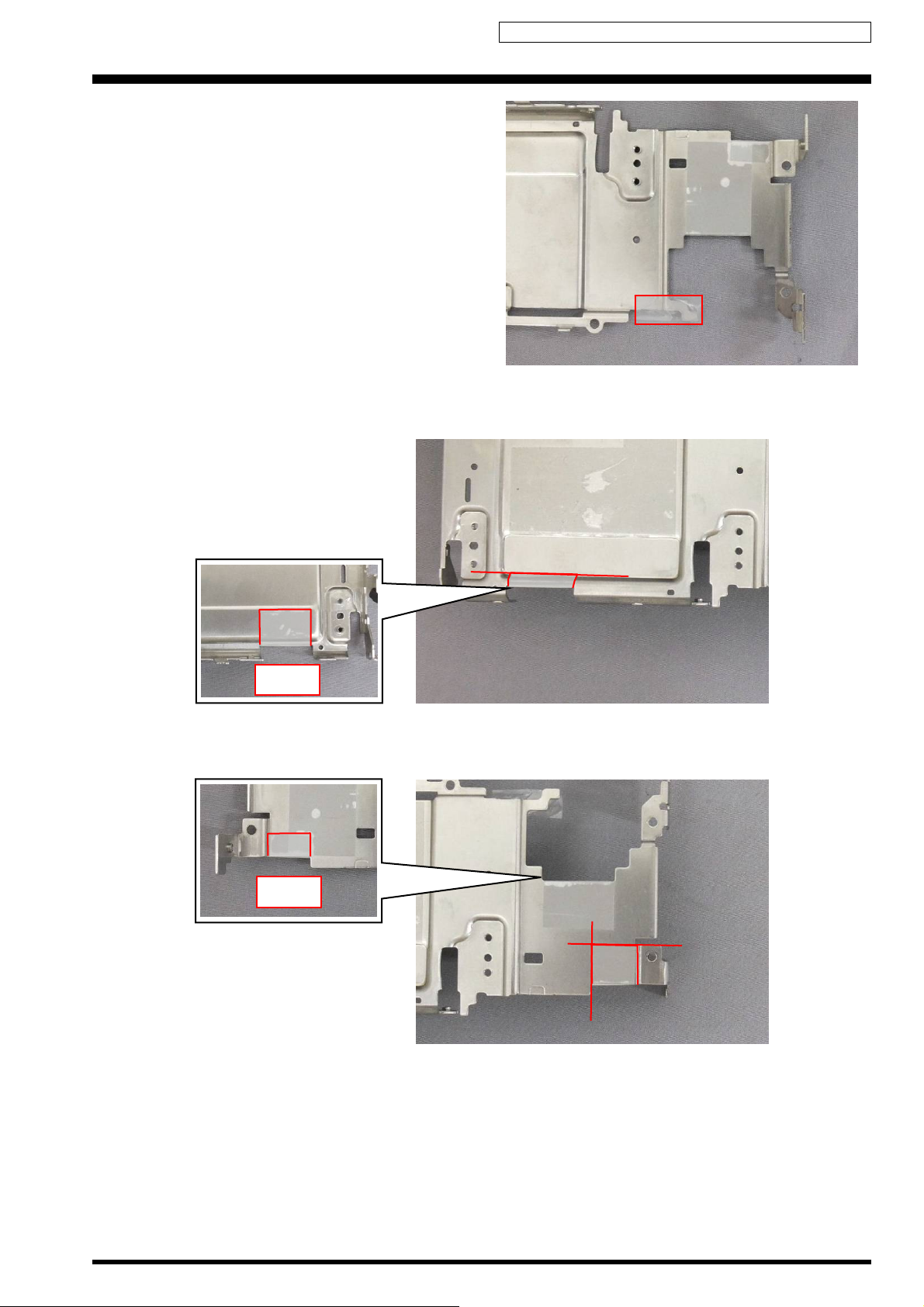
[Affixing position for the GASKET MAIN 2]
Affix the GASKET MAIN 2 on the MAIN_ASSY as shown in
the figure.
(15) Remove the REAR_FFC.
16
FFC
2-16

Confidential: FUJIFILM Service Center Use Only
2. Disassembly X-M1 Service Manual
[Notes on Assembly]
Affix the REAR_FFC after folding it like the picture below.
[Assembly]
Assemble procedure is reverse of the disassembly
procedure.
2-17
Confidential: FUJIFILM Service Center Use Only
X-M1 Service Manual 2. Disassembly
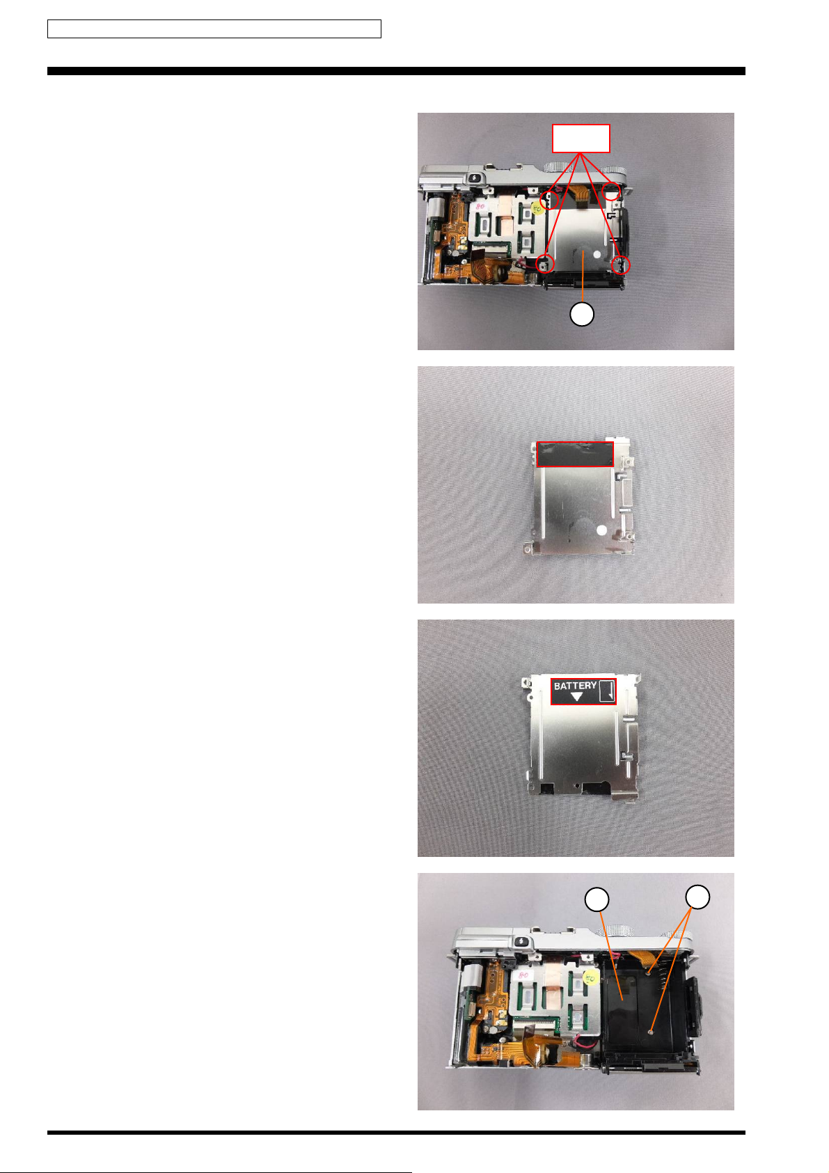
2-6. Removing the HOLDER BATTERY
(1) Remove the Hooks, and remove the PLATE HOLDER
BATT.
[Precaution when replacing PLATE HOLDER BATT]
UL TAPE (9X30mm) and LABEL BATT are not reusable.
[Affixing position for the UL TAPE (9X30mm)]
Affix the UL TAPE (9X30mm) on the PLATE HOLDER BATT
as shown in the figure.
UL TAPE (BLACK): ZS00143-100 (Width: 19mm)
Hooks
1
[Affixing position for the LABEL BATT]
Affix the LABEL BATT on the PLATE HOLDER BATT as
shown in the figure.
(2) Remove the 2 screws (BT2M1.7X4.5).
(3) Peel off the SHEET HEAT SINK 1.
3
2
2-18
Confidential: FUJIFILM Service Center Use Only
2. Disassembly X-M1 Service Manual
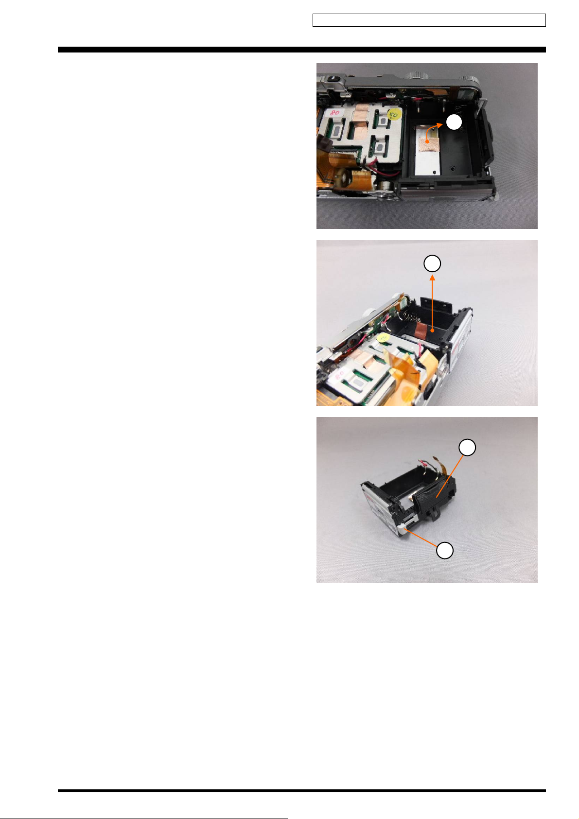
(4) Peel off the SHEET HEAT WLAN.
(5) Remove the CONST BATT in the direction of the arrow.
4
5
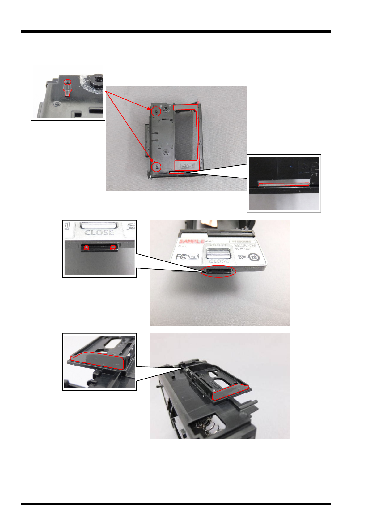
(6) Remove the COVER DC COUPLER.
(7) Remove the COVER JACK.
6
7
2-19
Confidential: FUJIFILM Service Center Use Only
X-M1 Service Manual 2. Disassembly
[Notes on Assembly]
Be sure to apply the lubricant to the CONST BATT.
• Lubricant: ZS00135-200 (SANKOL (CFD-409Z))
2-20
 Loading...