

Page 1
Instruction Manual
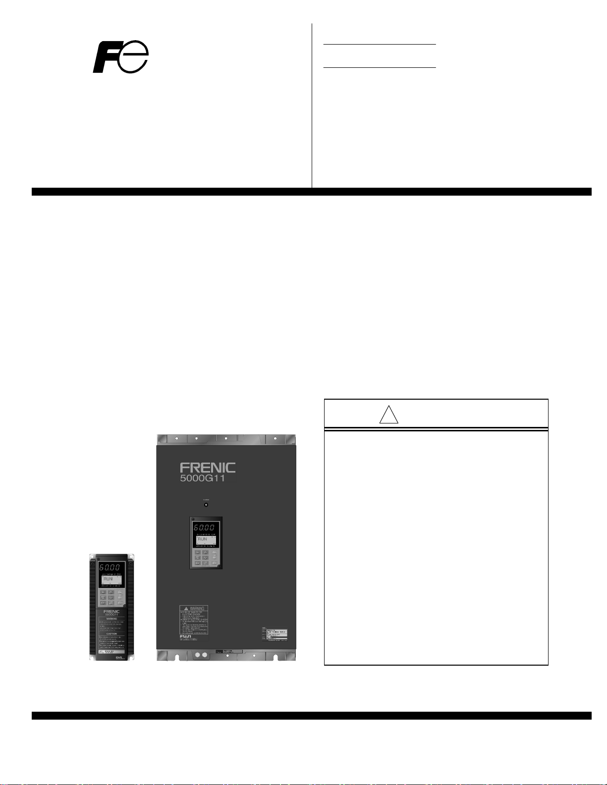
FRENIC 5000G11S/P11S
High-Performance, Low-Noise Inverter
General-Purpose Industrial Machines Fans and Pumps
230V Series 230V Series
1/4HP/FRNF25G11S-2UX 7.5HP/FRN007P11S-2UX
to 125HP/FRN125G11S-2UX to 150HP/FRN150P11S-2UX
460V Series 460V Series
1/2HP/FRNF50G11S-4UX 7.5HP/FRN007P11S-4UX
to 600HP/FRN600G11S-4UX to 800HP/FRN800P11S-4UX
!
CAUTION
Q Read all operating instructions before
installing, connecting (wiring),
operating, servicing, or inspecting the
inverter.
Q Ensure that this instruction manual is
made available to the final user of the
inverter.
Q Store this manual in a safe,
convenient location.
Q The product is subject to change
without prior notice.
Fuji Electric Systems Co., Ltd. INR-SI47-1206b-E
Fuji Electric Corp of America
Page 2
Preface
Thank you four purchasing our FRENIC5000G11S or FRENIC5000P11S series inverter. This product is used
to drive a 3-phase electric motor at variable speed. As incorrect use of this product may result in personal
injury and/or property damage, read all operating instructions before using.
As this manual does not cover the use of option cards, etc., refer to relevant manuals for option operations.
Safety Instructions
Read this manual carefully before installing, connecting (wiring), operating, servicing, or inspecting the inverter.
Familiarize yourself with all safety features before using the inverter.
In this manual, safety messages are classified as follows:
WARNING
CAUTION
Situations more serious than those covered by CAUTION will depend on prevailing circumstances.
Always follow instructions.
Improper operation may result in serious personal injury or death.
Improper operation may result in slight to medium personal injury or property
damage.
Instructions on use
WARNING
• This inverter is designed to drive a 3-phase induction motor and is not suitable for a single-phase motor or
others, as fire may result.
• This inverter may not be used (as is) as a component of a life-support system or other medical device
directly affecting the personal welfare of the user.
• This inverter is manufactured under strict quality control standards. However, safety equipment must be
installed if the failure of this device may result in personal injury and/or property damage.
There is a risk of accident.
Instructions on installation
WARNING
• Mount this inverter on an incombustible material such as metal.
There is a risk of fire.
• Do not place combustible or flammable material near this inverter, as fire may result.
CAUTION
• Do not hold or carry this inverter by the surface cover. Inverter may be dropped causing injury.
• Ensure that the inverter and heat sink surfaces are kept free of foreign matter (lint, paper dust, small chips
of wood or metal, and dust), as fire or accident may result.
• Do not install or operate a damaged inverter or an inverter with missing parts, as injury may result.
Page 3
Instructions on wiring
WARNING
• Connect the inverter to power via a line-protection molded-case circuit breaker or Fuse,
as fire may result.
• Always connect a ground wire, as electric shock or fire may result.
• A licensed specialist must perform the wiring works, as electric shock may result.
• Turn off the power before starting the wiring work, as electric shock may result.
• Wire the inverter after installation is complete, as electric shock or injury may occur.
CAUTION
• Confirm that the phases and rated voltage of this product match those of the AC power supply,
as injury may result.
• Do not connect the AC power supply to the output terminals (U,V,and W), as injury may result.
• Do not connect a braking resistor directly to the DC terminals (P(+)and N(-)), as fire may result.
• Ensure that the noise generated by the inverter, motor, or wiring does not adversely affect peripheral
sensors and equipment, as accident may result.
Instructions on operation
WARNING
• Be sure to install the surface cover before turning on the power (closed). Do not remove the cover while
power to the inverter is turned on.
Electric shock may occur.
• Do not operate switches with wet hands, as electric shock may result.
• When the retry function is selected, the inverter may restart automatically after tripping.
(Design the machine to ensure personal safety in the event of restart)
Accident may result.
• When the torque limiting function is selected, operating conditions may differ from preset conditions
(acceleration/deceleration time or speed). In this case, personal safety must be assured.
Accident may result.
• As the STOP key is effective only when a function setting has been established, install an emergency
switch independently, and when an operation via the external signal terminal is selected,
the STOP key on the keypad panel will be disabled.
Accident may result.
• As operations start suddenly if alarm is reset with a running signal input, confirm that no running signal
is input before resetting alarm.
Accident may result.
• Do not touch inverter terminals when energized even if inverter has stopped.
Electric shock may result.
CAUTION
• Do not start or stop the inverter using the main circuit power.
Failure may result.
• Do not touch the heat sink or braking resistor because they become very hot.
Burns may result.
• As the inverter can set high speed operation easily, carefully check the performance of motor or machine
before changing speed settings.
Injury may result.
• Do not use the inverter braking function for mechanical holding.
Injury may result.
Page 4
Instructions on maintenance, inspection, and replacement
WARNING
• Wait a minimum of five minutes (30HP or less) or ten minutes (40HP or more) after power has been tumed
off (open) before starting inspection. (Also confirm that the charge lamp is off and that DC voltage between
terminals P (+) and N (-) do not exceed 25V.)
Electrical shock may result.
• Only authorized personnel should perform maintenance, inspection, and replacement operations.(Take off
metal jewelry such as watches and rings. Use insulated tools.)
Electric shock or injury may result.
Instructions on disposal
CAUTION
• Treat as industrial waste when disposing it.
Injury may result.
Other instructions
WARNING
• Never modify the product.
Electric shock or injury may result.
Conformity to Low Voltage Directive in Europe
CAUTION
• The contact capacity of alarm output for any fault (30A, B, C) and relay signal output (Y5A, Y5C) is 0.5A at
48V DC.
• The ground terminal G should be connected to the ground.
Use a crimp terminal to connect a cable to the main circuit terminal or inverter ground terminal.
• Where RCD (Residual-current protective device) is used for protection in case of direct or indirect contact,
only RCD of type B is allowed on the supply side of this EE (Electric equipment).
Otherwise another protective measure shall be applied such as separation of the EE from the environment
by double or reinforced insulation or isolation of EE and supply system by the transformer.
• Use a single cable to connect the G inverter ground terminal. (Do not use two or more inverter ground
terminals.)
• Use a molded-case circuit breaker (MCCB) and magnetic contactor (MC) that conform to EN or IEC
standards.
• Use the inverter under over-voltage category III conditions and maintain Pollution degree 2 or better as
specified in IEC664. To maintain Pollution degree 2 or more, install the inverter in the control panel (IP54
or higher level) having structure free from water, oil, carbon, dust, etc.
• For the input-output wiring of the inverter, use cable (diameter and type) as specified in Appendix C in
EN60204.
• To ensure safety, install an optional AC reactor, DC reactor, or external braking resistor as follows:
1) Install inside an IP4X cabinet or barrier if electrical parts are exposed.
2) Install inside an IP2X cabinet or barrier if electrical parts are not exposed.
• It is necessary to install the inverter in appropriate method using an appropriate RFI filter to conform to the
EMC directive. It is customer's responsibility to check whether the equipment, the inverter is installed in,
conforms to EMC directive.
Page 5
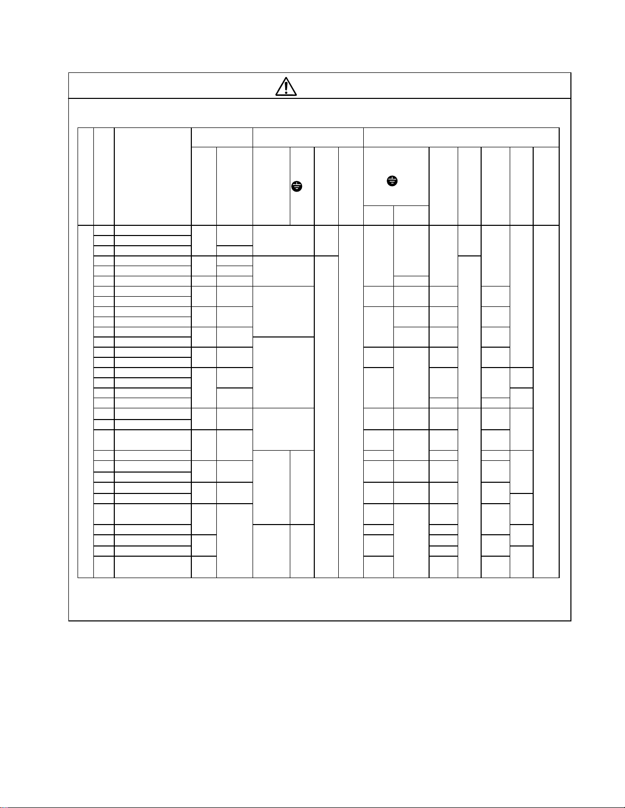
Conformity to Low Voltage Directive in Europe
CAUTION
Table 1-1 Applicable equipment and wire size for main circuit in Europe
Fuse/MCCB
current rating [A]
Tightening torque [N*m] Recommended wire size [mm
2
]
Inverter type
Voltage
Application motor [HP]
1/4 FRNF25G11S-2UX
1/2 FRNF50G11S-2UX
1 FRN001G11S-2UX
2 FRN002G11S-2UX 15
3 FRN003G11S-2UX
5 FRN005G11S-2UX 20 30
7.5 FRN007P11S-2UX 30 40 6(6) 10(10) 4 4
7.5 FRN007G11S-2UX
10 FRN010P11S-2UX 40 60 16 6 6
10 FRN010G11S-2UX (16)
15 FRN015P11S-2UX 50 100
15 FRN015G11S-2UX
20 FRN020P11S-2UX 75 125 25 16 16
20 FRN020G11S-2UX (16)
25 FRN025P11S-2UX 150 3.5
25 FRN025G11S-2UX
30 FRN030P11S-2UX 175
30 FRN030G11S-2UX
40 FRN040P11S-2UX 150 200 50
40 FRN040G11S-2UX (25) (25)
3phase 230V system
50 FRN050P11S-2UX 175 250
50 FRN050G11S-2UX 70(35)
60 FRN060P11S-2UX 200 300 95
60 FRN060G11S-2UX (50) (50)
75 FRN075P11S-2UX 250 350
75 FRN075G11S-2UX (35) (70)
100 FRN100P11S-2UX 350
100 FRN100G11S-2UX 185(95) 240
125 FRN125P11S-2UX 400 240
125 FRN125G11S-2UX (120) 300
150 FRN150P11S-2UX
With
DCR
5
10
100
500
Without
DCR
5
10
15
-
G
R0, T0
L1/R, L2/S, L3/T
U, V, W
P1, P (+), DB, N (-)
1.2 - -
1.8
3.5
5.8
1.2
13.5
27 13.5
48 27
L1/R, L2/S, L3/T
(
G)
Control
With
Without
DCR
(2.5)
(10)
(16)
0.7
16×2
(16)
35×270×235×2 50×2
50×2
(50)
95×295×2 120×2
(95)
DCR
2.5
10
35
2.5
(2.5)
4(4)
35 10 10
(16)
50
(25)
25×2
35×2
(35)
50×225×2 35×2
-
U, V, W
2.5 2.5
25 25
35
50
25×2 25×2
70 95
50×2 70×2
70×2 95×2
R0, T0
2.5
35
16×2
2.5
to
6
P1, P (+)
2.5
5.5
4
6
10
16
25
Control
P (+), DB, N (-)
0.2
to
0.75
Note: The type of wire is 75℃ (167ºF) 600V Grade heat-resistant polyvinyl chloride insulated wires (PVC).
The above-mentioned wire size are the recommended size under the condition of the ambient temperature
50℃ (122ºF) or lower.
Page 6
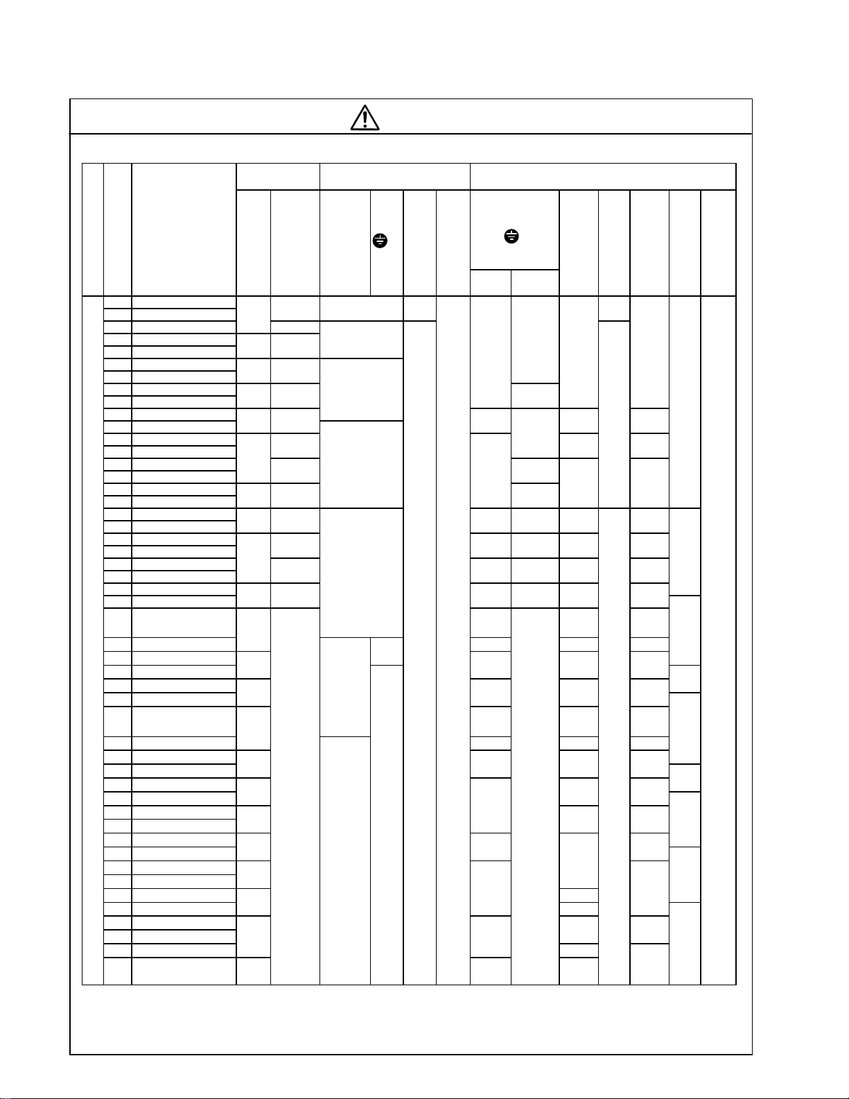
Conformity to Low Voltage Directive in Europe
(6)
(6)
(16)
(16)
(10)
(25)
(16)
(25)
(25)
(25)
(25)
(35)
(
)
CAUTION
Table 1-2 Applicable equipment and wire size for main circuit in Europe
Fuse/MCCB
current rating [A]
Tightening torque [N*m] Recommended wire size [mm
2
]
Inverter type
Voltage
Application motor [HP]
1/2 FRNF50G11S-4UX 1.2
1 FRN001G11S-4UX
2 FRN002G11S-4UX
3 FRN003G11S-4UX
5 FRN005G11S-4UX
7.5 FRN007P11S-4UX 15 20
7.5 FRN007G11S-4UX
10 FRN010P11S-4UX 20 30 6
10 FRN010G11S-4UX
15 FRN015P11S-4UX 30 40
15 FRN015G11S-4UX
20 FRN020P11S-4UX 50 6 6
20 FRN020G11S-4UX
25 FRN025P11S-4UX 60 16 10 10
25 FRN025G11S-4UX
30 FRN030P11S-4UX 50 75 25
30 FRN030G11S-4UX
40 FRN040P11S-4UX 75 100 16 35 25 25
40 FRN040G11S-4UX
50 FRN050P11S-4UX 125 25 50 35 35
50 FRN050G11S-4UX
60 FRN060P11S-4UX 150 35
60 FRN060G11S-4UX
75 FRN075P11S-4UX 125 175 50
75 FRN075G11S-4UX
100 FRN100P11S-4UX 175
100 FRN100G11S-4UX 70(35) 95 95
125 FRN125P11S-4UX 200
125 FRN125G11S-4UX (50)
150 FRN150P11S-4UX 225
3phase 460V system
150 FRN150G11S-4UX (50)
200 FRN200P11S-4UX 300
200 FRN200G11S-4UX 185(95) 2 40 240
250 FRN250P11S-4UX 350 240
250 FRN250G11S-4UX (120)
300 FRN300P11S-4UX 400
300 FRN300G11S-4UX
350 FRN350P11S-4UX 500
350 FRN350G11S-4UX
400 FRN400P11S-4UX 600
400 FRN400G11S-4UX (185)
450 FRN450P11S-4UX 700
450 FRN450G11S-4UX
500 FRN500P11S-4UX 800
500 FRN500G11S-4UX
600 FRN600P11S-4UX 1,000
600 FRN600G11S-4UX
700 FRN700P11S-4UX
800 FRN800P11S-4UX 1,200
With
Without
DCR
DCR
5
10 15
40
100
5 - -
10
-
L1/R, L2/S, L3/T
27
48
U, V, W
1.8
3.5
5.8
13.5
P1, P (+), DB, N (-)
13.5
G
R0, T0
1.2
27
L1/R, L2/S, L3/T
( G)
Control
With
Without
DCR
(2.5)
(10)
25×2
(25)
0.7
50×250×270×2
70×270×2
(70)
120×2
(120)
185×2 240×2 240×2
240×2
(240)
185×3
(300)
240×3
300
DCR
2.5
10
95
2.5
(2.5)
644
10
(10)
35×225×225×2
-
U, V, W
2.5 2.5
50 50
35×235×2
35×250×2
95×2 120×2
120×2 150×2
150×2 185×2
150×3
300×2
185×3 240×3
240×3 300×3
300×3
2.5
2.5
to
6
R0, T0
185×3
P1, P (+)
95×2
Note: The type of wire is 75℃ (167ºF) 600V Grade heat-resistant polyvinyl chloride insulated wires (PVC).
The above-mentioned wire size are the recommended size under the condition of the ambient temperature
50℃ (122ºF) or lower.
2.5
2.5
4
6
10
16
25
50
70
Control
P (+), DB, N (-)
0.2
to
0.75
Page 7

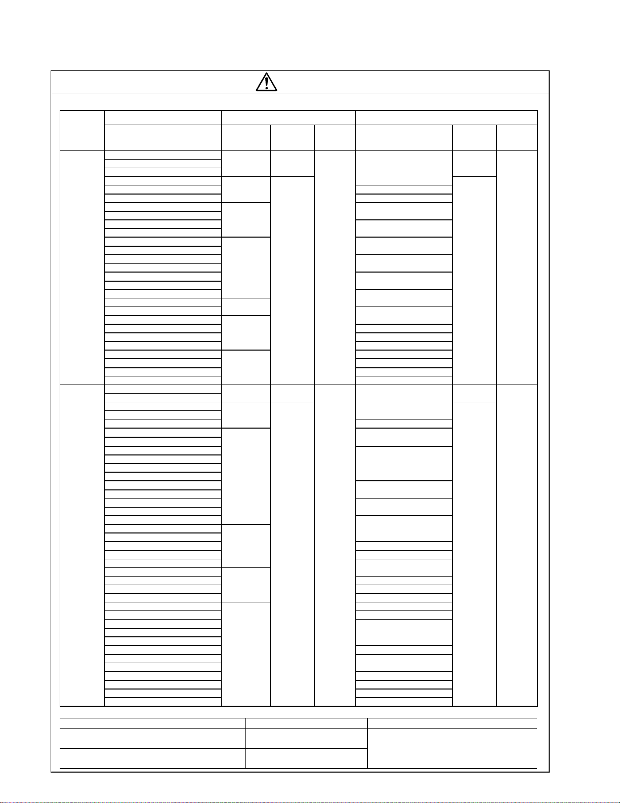
Compliance with UL/cUL standards [Applicable to products with UL/cUL mark]
CAUTION
• [CAUTION] Hazard of electrical shock. Disconnect incoming power before working on this control.
• [CAUTION] Dangerous voltage exists until charge lights is off.
• [WARNING]
• More than one live parts inside the inverter.
• Type1 “INDOOR USE ONLY”
The inverter is approved as a part used inside a panel. Install it inside a panel.
• Suitable for use on a circuit capable of delivering not more than 100,000rms symmetrical amperes.
• Use 60/75C copper wire only.
• A Class2 circuit wired with class1 wire.
• Field wiring connection must be made by a UL Listed and CSA Certified closed-loop terminal connector
sized for the wire gauge involved. Connector must be fixed using the crimp tool specified by the
connector manufacturer.
• Connect the power supply to main power supply terminals via the Molded-case circuit breaker (MCCB) or
a ground fault circuit interrupter (GFCI) to apply the UL Listing Mark.
(See Instruction Manual basic connection diagram Fig.2-3-1).
• In case of using auxiliary control-power input (R0, T0), connect it referring to Basic connection diagram
Fig.2-3-1.
• Solid state motor overload protection is provided in each model.
• Type 12 Enclosure at the back side only provided the mounting method is specifically defined, or
equivalent for models with suffix as FRNxxP11S-2xxxA2, FRNxxG11S-2xxxA2, FRNxxP11S-4xxxA2,
FRNxxG11S-4xxxA2 or FRNxxP11S-2DCxxxA2, FRNxxG11S-2DCxxxA2, FRNxxP11S-4DCxxxA2,
FRNxxG11S-4DCxxxA2, FRNxxP11S-2DMxxxA2, FRNxxG11S-2DMxxxA2, FRNxxP11S-4DMxxxA2,
FRNxxG11S-4DMxxxA2.
• Integral solid state short circuit protection does not provide branch circuit protection. Branch circuit
protection must be provided in accordance with the National Electrical Code and any additional local
codes.
General instructions
Although figures in this manual may show the inverter with covers and safety screens removed for
explanation purposes, do not operate the device until all such covers and screens have been replaced.
Page 8
Compliance with UL/cUL standards [Applicable to products with UL/cUL mark]
(
)
)
(
)
(
)
)
)
)
(
)
)
(
)
(
)
(
)
(
)
)
(
)
)
)
)
)
(
)
CAUTION
Tightening torque and wire range
Voltage
threephase
230V/
Single-
Phase
230V
three-
phase
460V/
Single
Phase
460V
Inverter type
G11S/P11S
FRNF25G11S-2UX
FRNF50G11S-2UX
FRN001G11S-2UX
FRN002G11S-2UX
FRN003G11S-2UX 14
FRN005G11S-2UX
FRN007G11S-2UX
FRN007,010P11S-2UX
FRN010G11S-2UX
FRN015P11S-2UX
FRN015G11S-2UX
FRN020P11S-2UX
FRN020G11S-2UX
FRN025P11S-2UX
FRN025G11S-2UX
FRN030P11S-2UX
FRN030G11S-2UX
FRN040G11S/P11S-2UX
FRN050P11S-2UX
FRN050G11S-2UX
FRN060G11S/P11S-2UX 3/0
FRN075G11S/P11S-2UX 4/0
FRN100P11S-2UX
FRN100G11S-2UX 350(177
FRN125P11S-2UX 2/0X2 (67.4X2)
FRN125G11S -2UX 500(253
FRN150P11S-2UX
FRNF50G11S-4UX
FRN001G11S-4UX
FRN002G11S-4UX
FRN003G11S-4UX
FRN005G11S-4UX
FRN007G11S-4UX
FRN007,010P11S-4UX
FRN010G11S-4UX
FRN015P11S-4UX
FRN015G11S-4UX
FRN020P11S-4UX
FRN020G11S-4UX
FRN025P11S-4UX
FRN025G11S-4UX
FRN030P11S-4UX
FRN030G11S-4UX
FRN040G11S/P11S-4UX
FRN050G11S/P11S-4UX
FRN060G11S/P11S-4UX 3
FRN075G11S/P11S-4UX 2
FRN100P11S-4UX
FRN100G11S-4UX
FRN125G11S/P11S-4UX 2/0
FRN150G11S/P11S-4UX 4/0
FRN200P11S-4UX
FRN200G11S-4UX 250
FRN250G11S/P11S-4UX 350(177
FRN300P11S-4UX
FRN300G11S-4UX
FRN350G11S/P11S-4UX
FRN400G11S/P11S-4UX 300X2(152X2)
FRN450P11S-4UX
FRN450G11S-4UX
FRN500G11S/P11S-4UX 500X2(253X2
FRN600G11S/P11S-4UX 600X2(304X2
FRN700P11S-4UX 500X3(253X3
FRN800P11S-4UX
Required torque [lb-inch](N.m)
Main
terminal
10.6(1.2) ― ―
15.9(1.8)
31.0(3.5)
51.3(5.8)
119(13.5)
239(27)
425(48)
10.6(1.2) ― ―
15.9(1.8)
31.0(3.5)
119(13.5)
239(27)
425(48)
Auxiliary
controlpower
10.6(1.2)
10.6(1.2)
Control
6.2(0.7)
6.2(0.7)
Use the following power supply to the inverter
FRNF25G11S-2UX ~ FRN125G11S-2UX AC240V (30HP or less)
FRN007P11S-2UX ~ FRN150P11S-2UX AC230V (40HP or less)
FRNF50G11S-4UX ~ FRN600G11S-4UX
FRN007P11S-4UX ~ FRN800P11S-4UX
Inverter Model Maximum input voltage Input source current
AC480V
16 (1.3)
10 (5.3
8 (8.4)
6 (13.3)
4 (21.2)
3 (26.7)
2 (33.6)
1 (42.4)
1/0 (53.5)
1/0X2(53.5X2
300X2
16 (1.3)
14 (2.1
12 (3.3)
10 (5.3)
8 (8.4)
6 (13.3)
4 (21.2)
1/0 (53.5)
1X2 (42.4X2
600(304)
350X2(177X2)
600X3
Wire range [AWG] (mm2)
L1/R,L2/S,L3/T
U,V,W
2.1
85.0
107.2
152X2
26.7
33.6
67.4
107.2
127
304X3
Not more than 100,000A
Auxiliary
controlpower
16(1.3)
16(1.3)
Control
24 (0.2)
24 (0.2)
Page 9
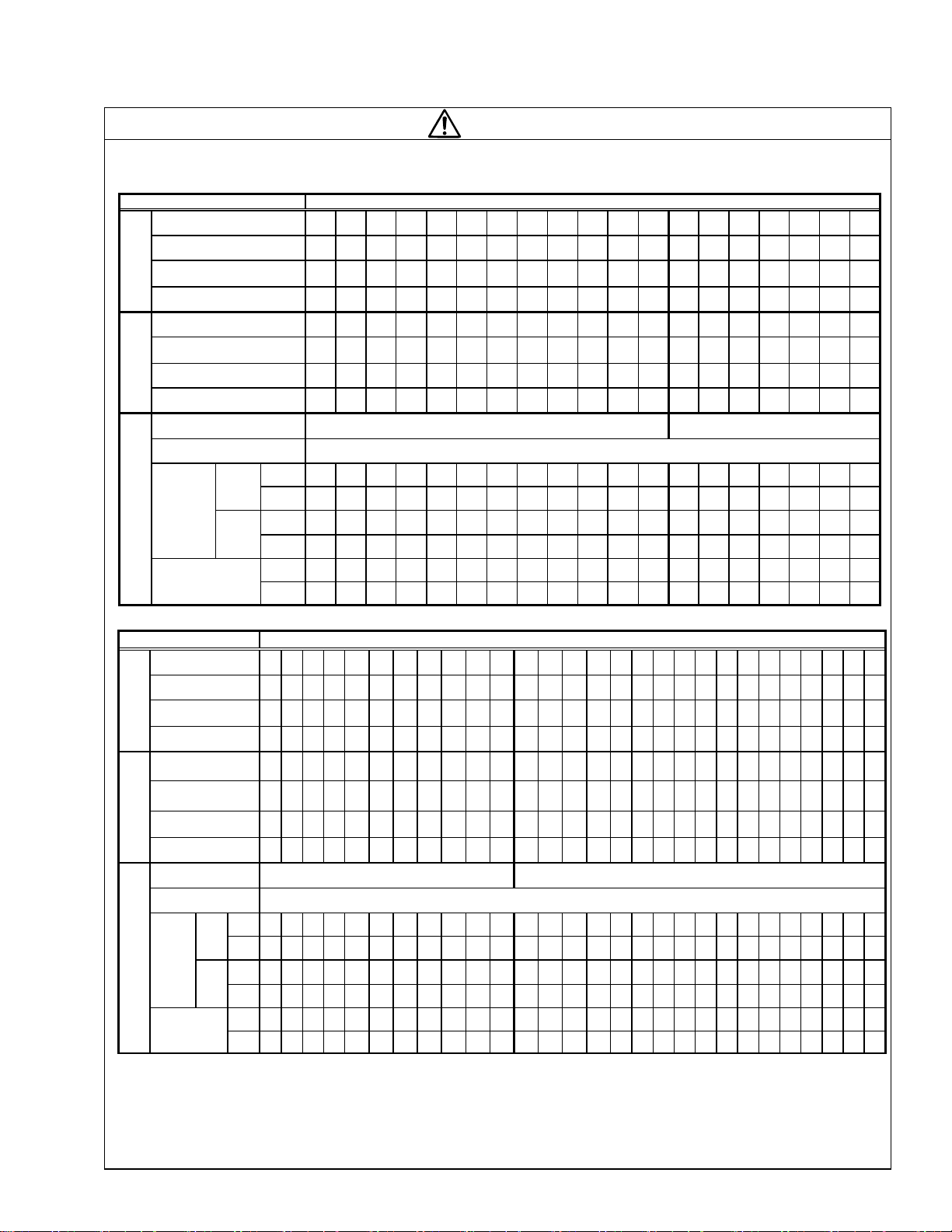
Compliance with UL/cUL standards [Applicable to products with UL/cUL mark]
(*6)
CAUTION
When applying the single-phase to the three-phase drive, the applied motor must fulfill the table below and specifications other than table
below are the same as those "Three-phase 230V ratings" and "Three-phase 460V ratings".
Single-phase 230V ratings
Items Specifications
Type
FRN[][][]G11S-2UX
Nominal applied
motor [HP]
G11
Rated output capacity (*1)
[kVA]
Rated output
current (*2) [A]
Type
FRN[][][]P11S-2UX
Nominal applied
motor [HP]
P11
Rated capacity (*1)
[kVA]
Rated output
current (*2) [A]
Phases, voltage,
frequency
Voltage/frequency
variations
(*3) [A]
Rated current
Input ratings
Required
power
with
DCR
G11
w/o
DCR
with
DCR
P11
w/o
DCR
supply
capacity
(*5)[kVA]
F25 F50 001 002 003 005 007 010 015 020 025 030 040 050 060 075 100 125 -
1/8 1/4 1/2 1 1.5 3 3 5 7.5 10 10 15 20 25 30 30 30 40 -
0.3 0.6 1.0 1.6 2.3 3.9 5.0 6.8 9.3 11 14 16 21 27 32 34 39 47 -
1.0 1.7 2.8 4.6 6.6 11 14 19 26 33 39 47 59.4 75 91 95 109 131 -
- - - - - - 007 010 015 020 025 030 040 050 060 075 100 125 150
- - - - - - 3 5 7.5 10 10 15 20 25 30 30 30 40 50
- - - - - - 4.6 6.1 8.7 11 12 16 21 27 32 34 36 44 51
- - - - - - 13 17 24.2 31 36 46.2 59.4 75 91 95 102 123 143
Single-phase, 200 to 230V, 50/60Hz
Voltage: +10% to -10%, Frequency: +5% to -5%
1.2 2.0 3.5 6.6 9.5 18.0 25.0 34.0 50.0 67.0 78.1 95.9 127 157 186 229 241 279 -
1.8 3.1 5.3 9.5 13.2 23.2 31.4 43.9 72.6 95.7 112 136 168 204 243 287 - - -
- - - - - - 25.0 34.0 50.0 67.0 79.9 93.9 125 156 185 198 223 262 310
- - - - - - 31.4 42.7 72.6 95.7 115 133 166 202 242 258 - - -
0.3 0.5 0.8 1.4 2.0 3.8 5.2 7.1 11 14 17 20 27 33 39 48 51 59 -
G11
- - - - - - 5.2 7.1 11 14 17 20 27 33 39 42 47 55 65
P11
Single-phase 460V ratings
Items Specifications
Type
FRN[][][]G11S-4UX
Nominal applied
motor [HP]
G11
Rated output
capacity (*1) [kVA]
Rated output
current (*2) [A]
Type
FRN[][][]P11S-4UX
Nominal applied
motor [HP]
P11
Rated capacity (*1)
[kVA]
Rated output
current (*2) [A]
Phases, voltage,
frequency
Voltage/frequency
variations
(*3) [A]
Input ratings
Rated current
supply
power
capacity
Required
(*1) Indicated capacities are at the rated output voltage 230V for the three-phase 230V input, 230V for the single-phase 230V input and
460V for the three-phase / single-phase 460V input. The rated capacity will be lowered if the supply voltage is lowered.
(*2) In the case of a low impedance load, such as a high-frequency motor, the current may drop below the rated current.
(*3) Calculated under Fuji-specified conditions.
(*4) The taps within the inverter must be changed for a power supply rated at 380 to 398V/50 Hz or 380 to 430V/60 Hz.
(*5) Indicates the values required when using a power-factor correcting DC reactor (DCR) (optional for inverters of 75HP or less) with a
loaded nominal applied motor.
At single-phase input use, the output voltage may be lower than three-phase input.
F50 001 002 003 005 007 010 015 020 025 030 040 050 060 075 100 125 150 200 250 300 350 400 450 500 600 - -
1/4 1/2 1 1.5 3 3 5 7.5 10 10 15 20 25 30 30 40 50 60 60 75 100 100 125 150 150 200 - -
0.7 1.1 1.8 2.3 4.4 6.7 9.5 11 14 18 20 26 33 39 47 48 57 68 82 97 118 133 162 184 206 236 - -
0.9 1.5 2.3 3.0 5.6 8.5 12 15 18 23 26 33 42 49 59 61 72 86 103 122 149 167 204 231 259 297 - -
- - - - - 007 010 015 020 025 030 040 050 060 075 100 125 150 200 250 300 350 400 450 500 600 700 800
- - - - - 3 5 7.5 10 10 15 20 25 30 30 30 40 50 60 75 100 100 125 125 150 200 200 250
- - - - - 6.5 8.7 11 14 17 19 25 31 36 43 47 55 65 78 96 116 128 155 160 198 229 259 305
- - - - - 8.2 11 14 18 22 25 32 39 46 54 59 70 82 99 121 146 161 195 202 250 288 326 384
Single-phase,380 to 480V,50/60Hz
Voltage: +10% to -10%, Frequency: +5% to -5%
with
1.0 1.8 3.5 4.7 8.5 13.0 18.0 25.0 33.3 39.6 47.5 63.1 76.9 91.9 110 113 137 164 192 234 286 319 395 446 512 575 - -
DCR
G11
P11
(*5)[kVA]
w/o
DCR
with
DCR
w/o
DCR
3.1
1.7
5.9 8.2 13.0 19.3 24.8 38.3 50.3 59.9 69.3 86.0 104 124 145 - - - - - - - - - - - - -
- - - - - 13.0 18.0 25.0 32.8 38.9 45.4 58.7 72.2 85.8 99.7 110 132 158 188 226 283 309 362 392 492 558 633 717
-
-
- - - 19.3 24.8 38.3 49.7 58.9 68.8 85.5 98.5 116 134 - - - - - - - - - - - - -
0.5 0.9 1.7 2.2 4.0 6.0 8.3 12 16 19 22 30 36 43 51 53 63 76 89 108 132 147 182 206 236 265 - -
G11
- - - - - 6.0 8.3 12 16 18 21 28 34 40 46 51 61 73 87 105 130 143 167 181 227 257 291 330
P11
Single-phase, 200 to 220V/50Hz
Single-phase, 200 to 230V/60Hz
Single-phase, 380 to 440V/50Hz *4)
Single-phase, 380 to 480V/60Hz
Page 10

Contents
1. Before Using This Product ····························1-1
1-1 Receiving Inspections ······························1-1
1-2 Appearance ·············································1-1
1-3 Handling the Product ······························· 1-2
1-4 Carrying ···················································1-3
1-5 Storage ···················································· 1-3
2. Installation and Connection ···························2-1
2-1 Operating Environment ····························2-1
2-2 Installation Method ···································2-1
2-3 Connection ··············································2-3
2-3-1 Basic connection ·······························2-3
2-3-2 Connecting the main circuit and
ground terminals ·····························2-8
2-3-3 Connecting the control terminals ······2-13
2-3-4 Terminal arrangement ······················2-16
2-3-5 Applicable equipment and wire size
for main circuit ·······························2-18
3. Operation ·······················································3-1
3-1 Inspection and Preparation
before Operation ······································3-1
3-2 Operation Method ···································· 3-1
3-3 Trial Run ·················································· 3-1
4. Keypad Panel ················································4-1
4-1 Appearance of Keypad Panel ··················4-1
4-2 Keypad Panel Operation System
(LCD screen, Level Structure) ················4-2
4-2-1 Normal operation ······························4-2
4-2-2 Alarm occurrence ·····························4-2
4-3 Operating Keypad Panel ··························4-4
4-3-1 Operation Mode ································4-4
4-3-2 Setting digital frequency ····················4-4
4-3-3 Switching the LED monitor ···············4-5
4-3-4 Menu screen ·····································4-5
4-3-5 Setting function data ·························4-5
4-3-6 Checking function data ·····················4-7
4-3-7 Monitoring operating status ··············4-7
4-3-8 I/O check ··········································4-8
4-3-9 Maintenance information ··················4-9
4-3-10 Load rate measurement ···············4-10
4-3-11 Alarm information ························· 4-11
4-3-12 Alarm history and factors ················4-12
4-3-13 Data copy ······································4-13
4-3-14 Alarm mode ·································· 4-15
5. Function Select ············································· 5-1
5-1 Function select list ··································· 5-1
5-2 Function Explanation ······························· 5-7
6. Protective Operation ····································· 6-1
6-1 List of Protective Operations ··················· 6-1
6-2 Alarm Reset ············································ 6-2
7. Trouble shooting ··········································· 7-1
7-1 Protective function activation ·················· 7-1
7-2 Abnormal motor rotation ························· 7-5
8. Maintenance and Inspection ························· 8-1
8-1 Daily Inspection ······································· 8-1
8-2 Periodical Inspection ······························· 8-1
8-3 Measurement of Main Circuit
Electrical Quantity ···································· 8-4
8-4 Insulation Test ········································· 8-5
8-5 Parts Replacement ································· 8-5
8-6 Inquiries about Products and
Product Guarantee ································· 8-5
9. Specifications ················································ 9-1
9-1 Standard Specifications ·························· 9-1
9-2 Common Specifications ·························· 9-3
9-3 Outline Dimensions ································· 9-4
9-4 RS-485 Modbus RTU Serial
Communications ···································· 9-8
9-4-1 Transmission Specification ················ 9-8
9-4-2 Connection ········································· 9-8
9-4-3 Serial Interface Configuration ············ 9-8
9-4-4 Modbus RTU Functions ····················· 9-8
9-4-5 Inverter Function Code Access ·········· 9-9
9-4-6 Command and Monitor
Data Registers·································· 9-9
9-4-7 Data Format Specification················ 9-11
9-4-8 Communication Errors ····················· 9-15
10. Options ······················································ 10-1
10-1 Built-in Options ···································· 10-1
10-2 Separately Installed Options ··············· 10-2
11. Electromagnetic compatibility (EMC) ········ 11-1
11-1 General ··············································· 11-1
11-2 Recommended Installation
Instructions ········································· 11-2
11-3 The harmonics restriction
in Europe Union (EU) ························· 11-5
Appendix
App. Inverter Generating Loss ························A-1
Page 11

2008-06 (K07/K07) 10CM
Page 12
1. Before Using This Product
1-1 Receiving Inspections
Unpack and check the product as explained below.
If you have any questions about the product, contact
the nearest Fuji sales office or your local distributor
where you purchased the unit.
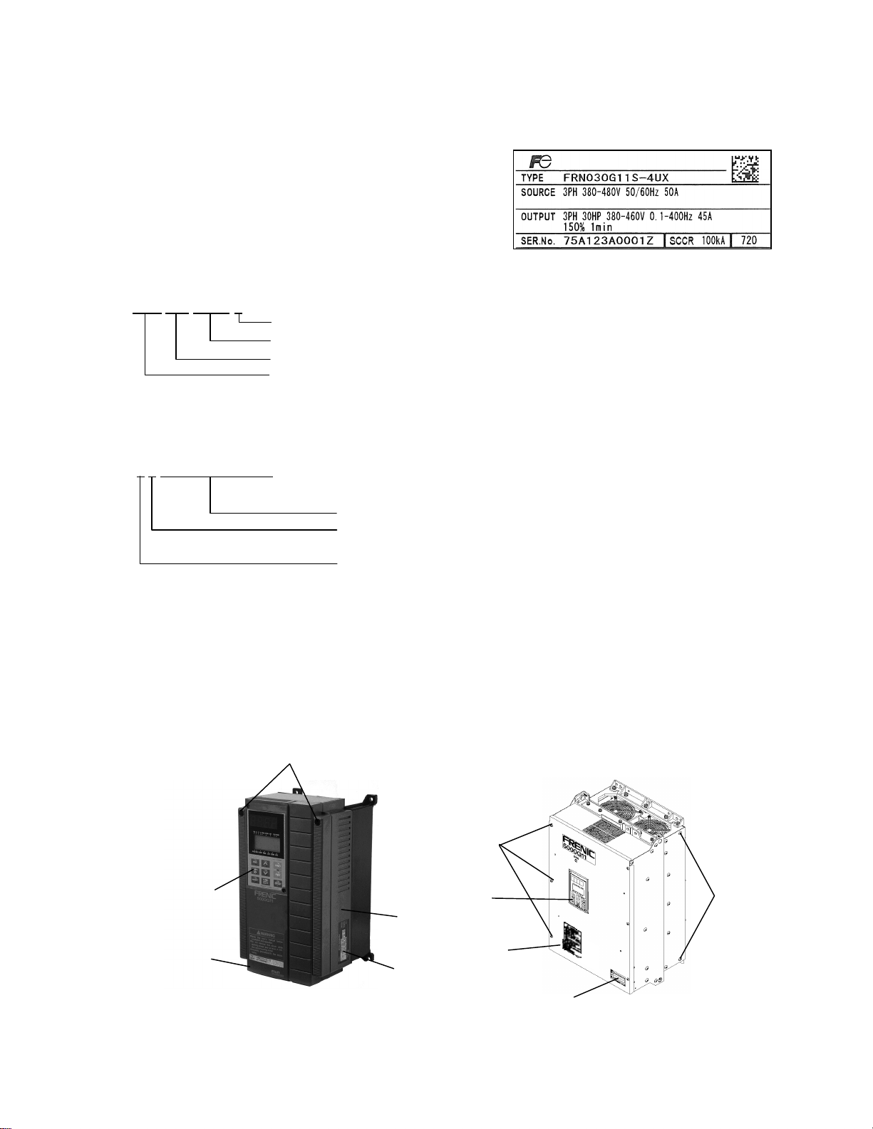
① Check the ratings nameplate to confirm that the
delivered product is the ordered one.
TYPE : Inverter type
FRN 030 G11S-4 UX Power supply voltage system
:2→ 230V grade、4→460V grade
SOURCE : Power rating
OUTPUT : Output rating
MASS : Mass (not indicated for products with 30HP or less)
SER.No. : Serial number
7
5 A 123A0001Z
Production lot serial number
Production month:1 to 9: January to September,
X: October, Y: November, Z: December
Series name:G11S or P11S
Nominal applied motor:030→30HP
Product type: FRENIC5000
Production year: Last digit of year (7 --> 2007)
② Check for damaged and/or missing parts upon delivery.
③ In addition to the inverter unit and this manual, the package contains rubber bushing (for products with 30HP
or less) and a terminating resistor (1/2 W, 120Ω). The terminating resistors for products with 30HP or less
is packed in a sack. The terminating resistors for products with 40HP or more is connected to the control
terminal of the inverter unit. This terminating resistor is required for RS-485 communication. The
terminating resistor need not be removed regardless of RS-485 communication status.
Use the “J2” connector on the control board to turn on or off the terminating resistor.
Ratings nameplate
1-2 Appearance
Mounting screws of surface cover
Keypad panel
Surface cover
Mounting screws of
surface cover
(6 screws total)
Keypad panel
Intermediate cover
Surface cover
Ratings nameplate
Ratings nameplate
30HP or less 40HP or more
1-1
Lifting holes
(4 holes total)
Page 13
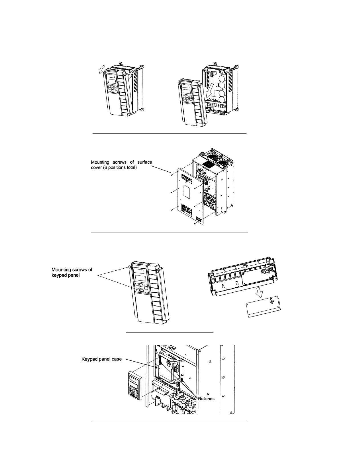
1-3 Handling the Product
(1) Removing the surface cover
For the inverter of 30HP or less, loosen the mounting screws of the surface cover, then remove the cover
by pulling the top (see Figure 1.3.1).
Fig. 1-3-1 Removing the surface cover (for inverter of 30HP or less)
For the inverter of 40HP or more, remove the six mounting screws of the surface cover, then
remove the surface cover.
Fig. 1-3-2 Removing the surface cover (for inverter of 40HP or more)
(2) Removing the keypad panel
After removing the surface cover as explained in (1), loosen the mounting screws of the
keypad panel and remove as shown in Figure 1.3.3.
Fig. 1-3-3 Removing the keypad panel
Loosen the mounting screws of the keypad panel and remove using the finger holds on the
keypad panel case.
Fig. 1-3-4 Removing the keypad panel (for inverter of 40HP or more)
1-2
Page 14

1-4 Carrying
Carry the product by the main unit.
Do not carry the product while holding the cover or parts other than the main unit.
Use a crane or hoist to carry a product equipped with hanging holes.
1-5 Storage
Temporary storage
Temporary storage of this product must meet those conditions listed in Table 1-5-1.
Table 1-5-1 Storage environment
Item Specifications
Ambient
temperature
Storage
temperature
Relative
humidity
Atmosphere Pollution degree 2
Air pressure
Note1: The storage temperature applies only to short periods such as transport.
Note2: As a large change in temperature within this humidity range may result in condensation or freezing, do not store
where such temperature changes may occur.
① Do not place this product directly on a floor.
② To store the product in an extreme environment, pack in vinyl sheet, etc.
③ If the product is stored in a high-humidity environment, insert a drying agent (e.g., silica gel) and pack the
product in vinyl sheet.
-10℃(14ºF) to +50℃(122ºF)
-25℃(-13ºF) to +65℃(149ºF)
Note2
5 to 95%
Operation/storage: 86 to 106 kPa
Transport : 70 to 106 kPa
Condensation or freezing must not occur as a result of
sudden temperature changes.
Long-term storage
If the product is to be stored for an extended period after purchase, the method of storage depends
primarily on storage location.
The general long-term storage method is as follows:
① The above conditions for temporary storage must be satisfied.
When the storage period exceeds three months, the upper limit of ambient temperature must be reduced
to 30℃(86ºF) to prevent the deterioration of the electrolytic capacitors.
② Pack the product thoroughly to eliminate exposure to moisture and include a drying agent to ensure a
relative humidity of about 70% or less.
③ If the product is mounted on a unit or control panel and is left unused and exposed to the elements like
moisture or dust (particularly on a construction site), remove the product and store in a suitable
environment.
④ Electrolytic capacitors not provided with power for an extended period will deteriorate. Do not store
electrolytic capacitors for one year or longer without providing power.
1-3
Page 15
2. Installation and Connection
2-1 Operating Environment
Install this product in a location that meets those conditions listed in Table 2-1-1
Table 2-1-1 Operating environment
Item Specifications
Location Indoor
-10℃(14ºF) to +50℃(122ºF)(For products of
Ambient
temperature
humidity
Atmosphere Pollution degree 2
Air pressure 86 to 106 kPa
Vibration
30HP or less, the ventilating covers must be
removed if ambient temperature exceeds
+40℃(104ºF))
5 to 95% (No condensation)
3mm:from 2 to less than 9 Hz, 1m/s
less than 20 Hz, 1m/s
Hz, 1m/s
2
:from 55 to less than 200 Hz
2
:from 20 to less than 55
2
:from 9 to
Table 2-1-2 Output current reduction rate
based on altitude
Altitude Output current
3300ft (1000m) or lower 1.00
3300-4950ft (1000 to 1500m) 0.97
4950-6600ft (1500 to 2000m) 0.95
6600-8250ft (2000 to 2500m) 0.91 Relative
8250-9900ft (2500 to 3000m) 0.88
3.9inch(100mm)
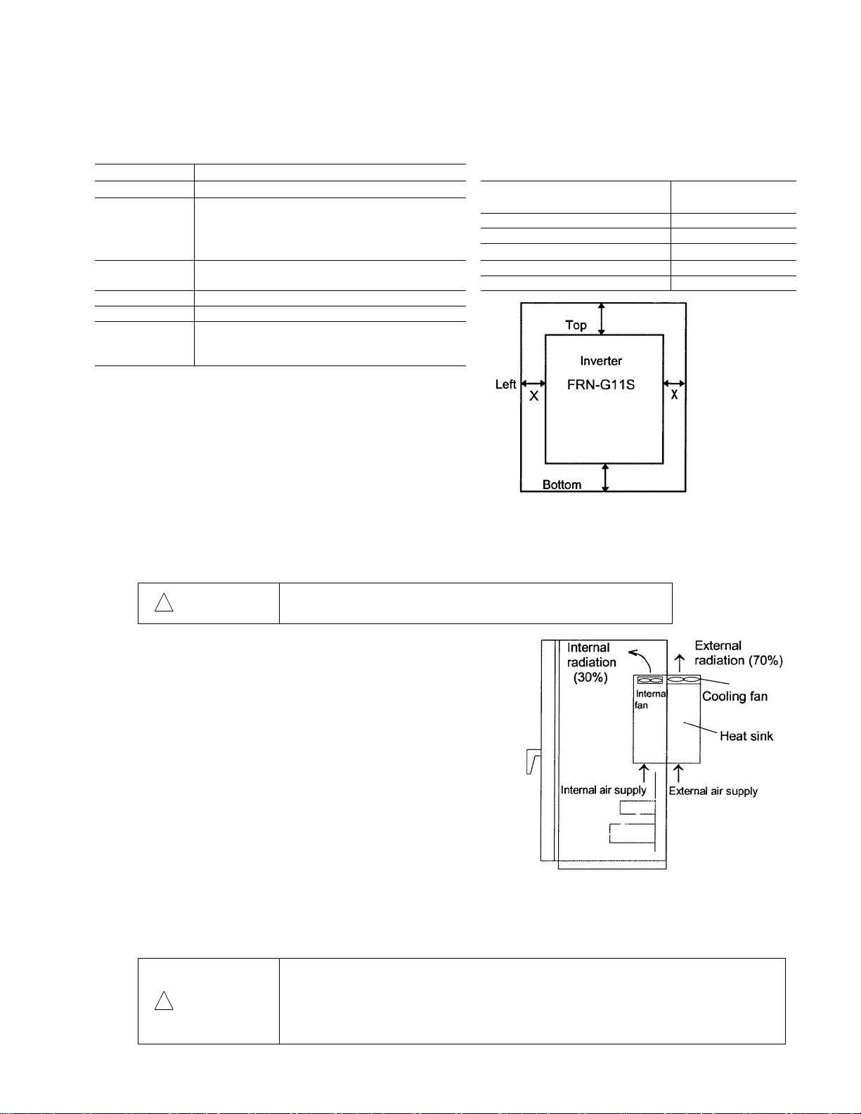
2-2 Installation Method
① Securely fasten the product in an upright position on a
solid structure such that FRENIC5000G11S is facing
the front.
Do not turn the product upside down or install in a
horizontal position.
3.9inch(100mm)
Fig.2-2-1
reduction rate
Right
30HP or less:
Gap X can be 0.
(side-by-side
installation)
40HP or more:
Gap X >= 2inch (50mm)
② As heat is generated during inverter operation, the spaces shown in Fig. 2-2-1 are required to ensure
sufficient cooling. As heat radiates upward, do not install the product beneath a device sensitive to heat.
③ As the heat sink may reach a temperature of 90℃(194ºF) during inverter operation, ensure that the
material surrounding the product can withstand this temperature.
!
WARNING
Install this product on nonflammable material such as metal.
④ When installing this product in a control panel, consider
ventilation to prevent ambient temperature of the inverter
from exceeding the specified value. Do not install the
product in an area from which heat cannot be sufficiently
released.
⑤ If two or more inverters must be installed in the same device
or control panel, arrange the units horizontally to minimize
the effect of heat. If two or more inverters must be installed
vertically, place an insulated plate between the inverters to
minimize the effect of heat.
⑥ When shipped from the factory, inverters are internal cooling
type inside panel. An inverter of 30HP or less can be
converted to an external cooling type simply by adding an
optional mounting adapter. An inverter of 40HP or more
can be converted simply by moving mounting adapter.
Fig.2-2-2
In an external cooling system, a heat sink radiating about 70% of total inverter heat (total loss) can be
placed outside the device or control panel.
Ensure that heat sink surfaces are kept free of foreign matter (lint, Fig. 2-2-2 External cooling system moist
dust particles etc.).
・In case of external cooling system, cover the inverter rear side in order not to
touch the main capacitor and braking resistor. Electric shock may result.
!
WARNING
・Ensure that the inverter and heat sink surfaces are kept free of foreign matter
such as lint, paper dust, small chips of wood or metal, and dust.
Fire or accident may result.
2-1
Page 16
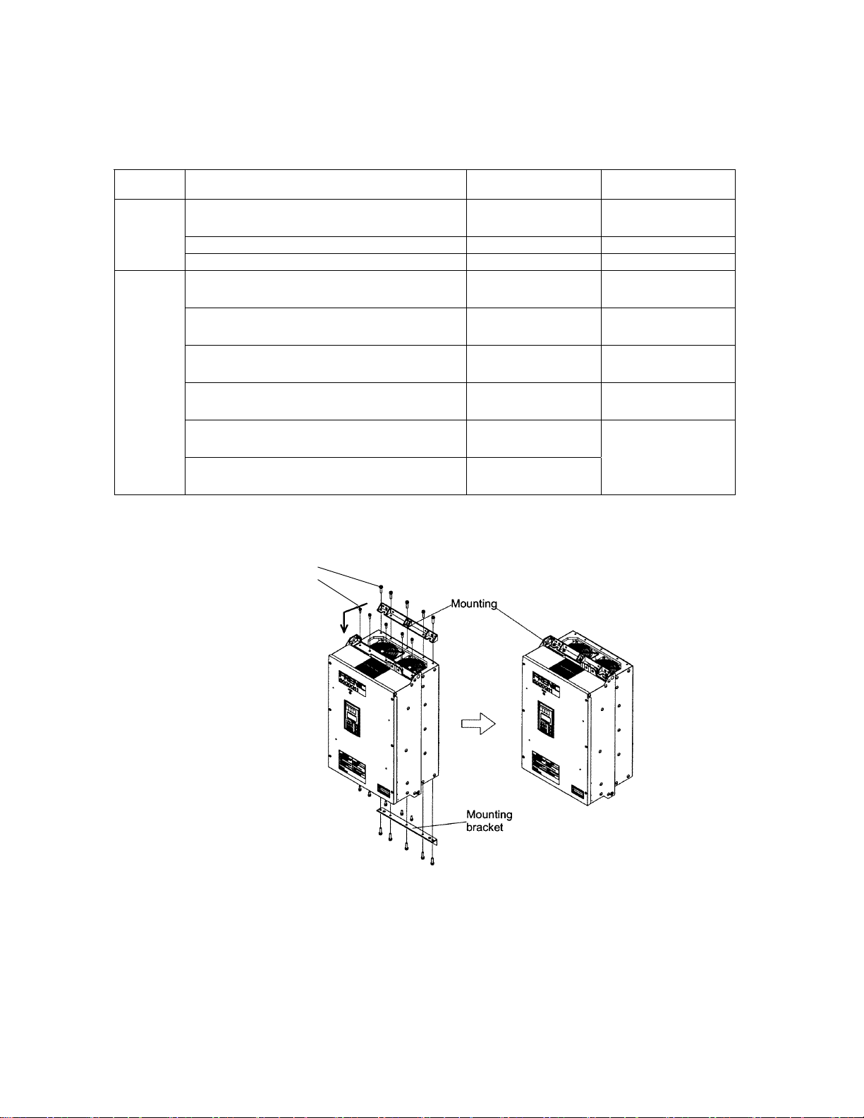
An inverter of 40HP or more can be converted to an external cooling type simply by moving upper and
lower mounting brackets as shown in Fig. 2-2-3. Remove the bracket screws, move the brackets, then
secure the brackets using the case mounting screws. (The bracket screws are no longer required after
changing the bracket mounting position.)
Quantity and size of mounting screws
Voltage
series
230V
FRN040G11S-2~FRN075G11S-2
FRN040P11S-2~FRN100P11S-2
Inverter type Bracket screws
5(M6×20) 5(M5×16)
FRN100G11S-2,FRN125P11S-2 7(M6×20) 7(M5×16)
Case mounting
screws
FRN125G11S-2,FRN150P11S-2 6(M6×20) 6(M5×16)
FRN040G11S-4~FRN100G11S-4
FRN040P11S-4~FRN125P11S-4
FRN125G11S-4~FRN150G11S-4
FRN150P11S-4~FRN200P11S-4
FRN200G11S-4~FRN250G11S-4
460V
FRN250P11S-4~FRN300P11S-4
FRN250G11S-4~FRN350G11S-4
FRN350P11S-4~FRN450P11S-4
FRN400G11S-4~FRN450G11S-4 Note 3)
FRN500P11S-4~FRN600P11S-4 Note 3)
FRN500G11S-4~FRN600G11S-4 Note 3)
FRN700P11S-4~FRN800P11S-4 Note 3)
5(M6×20) 5(M5×16)
7(M6×20) 5(M5×16)Note 1)
7(M6×20) 7(M5×16)
6(M6×20) 6(M5×16)Note 1)
6(M8×20)
- Note 2)
8(M8×20)
Note 1: Exchange the screws to M5 × 20 and secure the brackets with them.
Note 2: Secure the brackets using the bracket screws.
Note 3: The lower mounting brackets are not required to settle the inverter on the floor.
Bracket screws
Case mounting screws
Fig. 2-2-3
2-2
Page 17
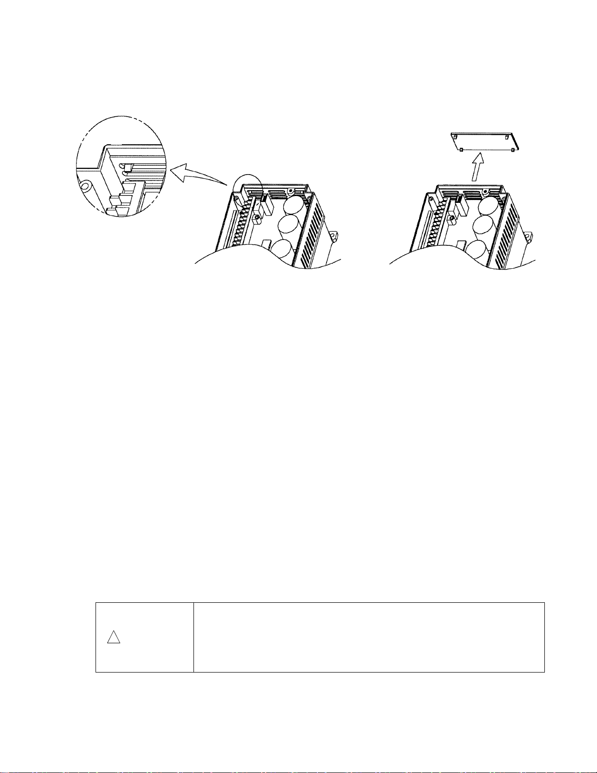
⑦ For inverters of 30HP or less, remove the ventilating covers if ambient temperature exceeds +40℃(104ºF)
(1) Removing the ventilating covers
One ventilating cover is mounted on top of the inverter and two or three are mounted at the bottom.
Remove the surface cover, then remove ventilating covers by popping out the cover inserts as shown in
Fig.2-2-4.
Fig. 2-2-4 Removing the ventilating cover
2-3 Connection
Remove the surface cover before connecting the terminal blocks as follows.
2-3-1 Basic connection
①Always connect power to the L1/R, L2/S, and L3/T main circuit power terminals of the inverter.
Connecting power to another terminal will damage the inverter. Check that the power voltage is
within the maximum allowable voltage marked on the nameplate, etc.
②Always ground the ground terminal to prevent disasters such as fire or electric shock and to
minimize noise.
③Use a reliable crimp terminal for connection between a terminal and a cable.
④After terminating the connection(wiring), confirm the following:
a. Confirm that the connection is correct.
b. Confirm that all necessary connections have been made.
c. Confirm that there is no short-circuit or ground fault between terminals and cables.
⑤Connection modification after power-on
The smoothing capacitor in the direct current portion of the main circuit cannot be discharged
immediately after the power is turned off. To ensure safety, use a multimeter to check that the
voltage of the direct current (DC) is lowered to the safety range (25V DC or less)after the charge
lamp goes off. Also, confirm that the voltage is zero before short-circuiting. The residual voltage
(electric charge) may causesparks.
• Always connect a ground wire.
Electric shock or fire may result.
!
WARNING
• Ensure that a licensed specialist performs all wiring works.
• Confirm that the power is turned off (open) before commencing wiring
operations.
Electrical shock may result.
2-3
Page 18
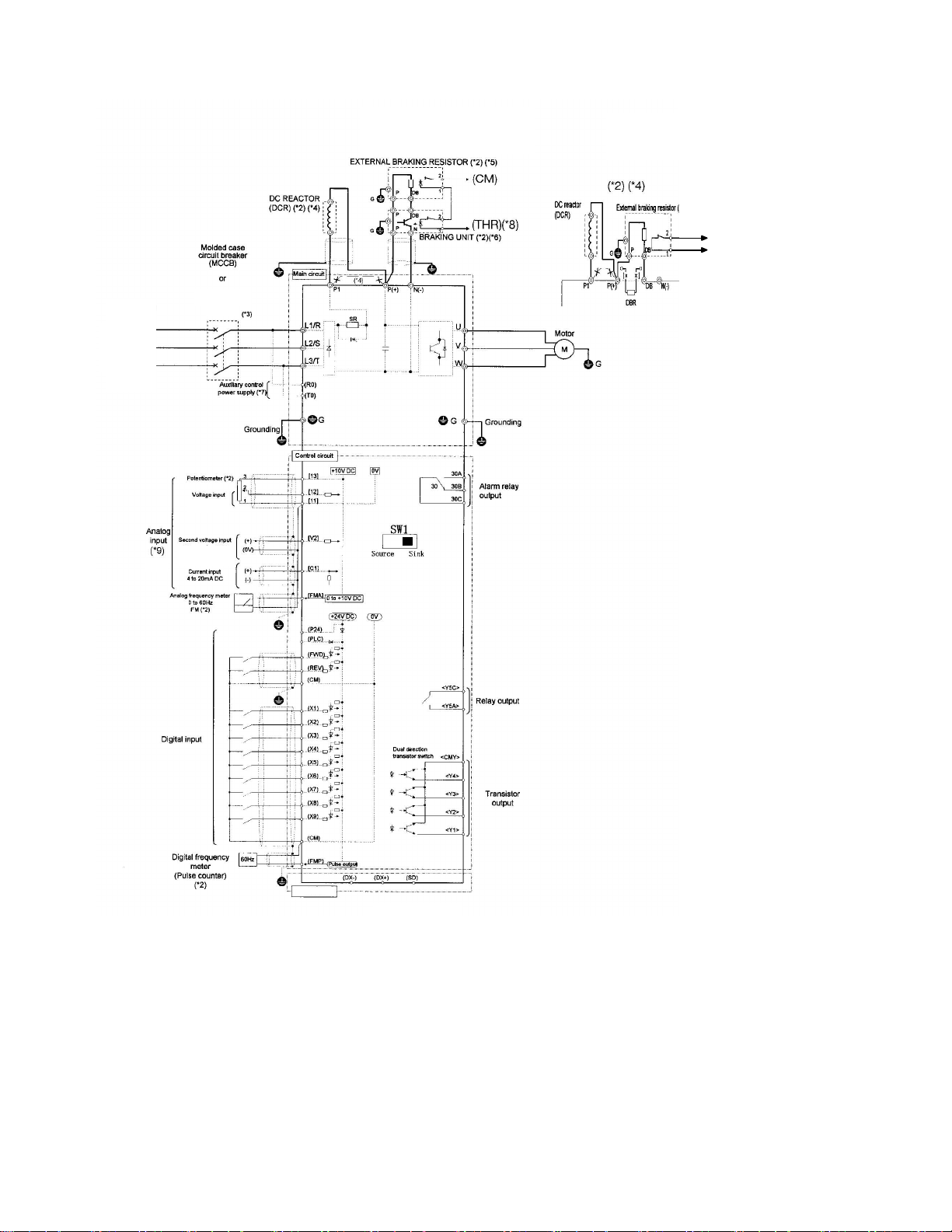
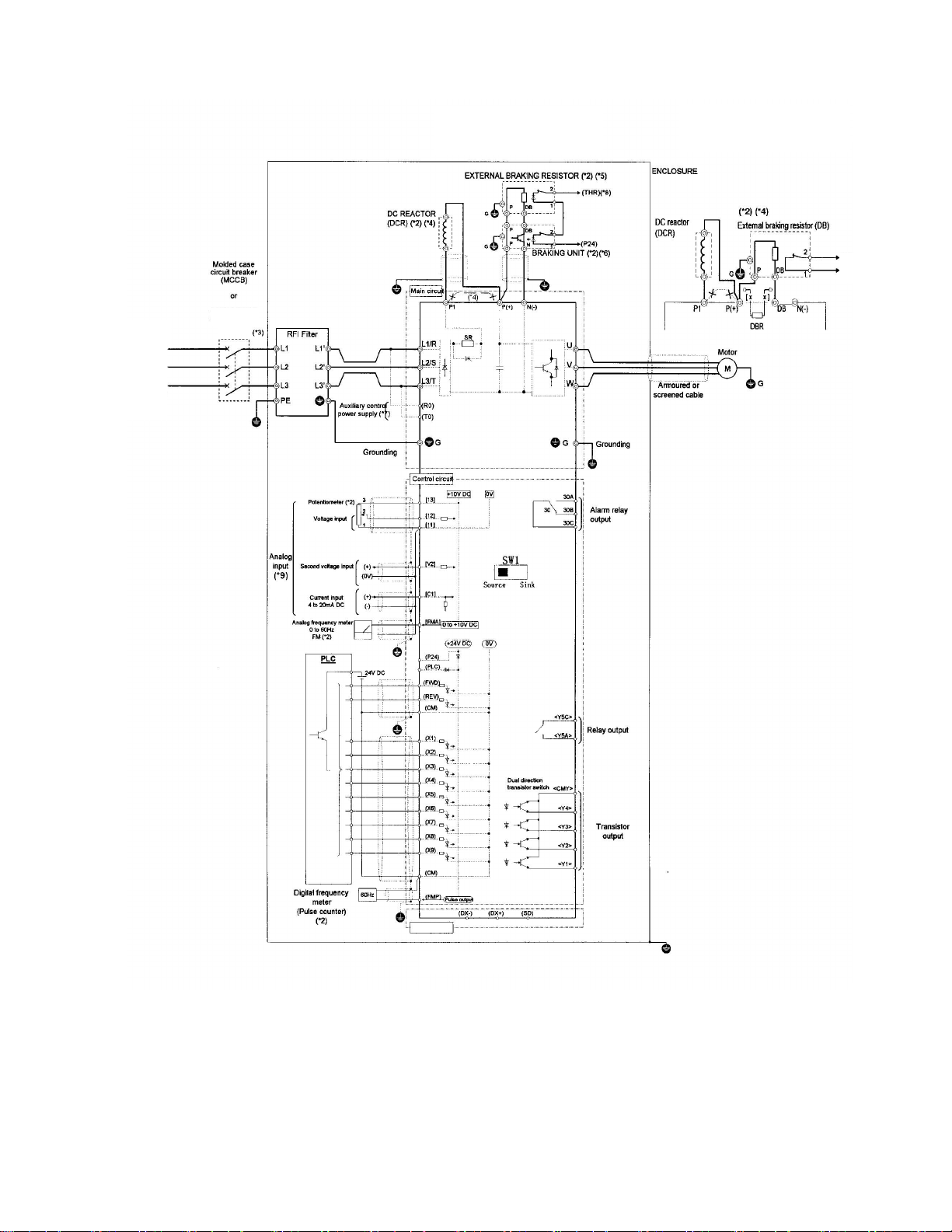
Basic Connection Diagram (Sink Logic)
Please refer to
9.1
Standard
specifications
for detail.
Ground-faul t
circuit interrupter
(GFCI)
0 to +/- 10V
0 to 10V
G11S:15HP and above
P11S:20HP and above
G11S:Up to 10HP
P11S:Up to 15HP
DB)
(CM)
(THR)
(*10)
RS-485
Fig.2-3-1
Note: The control circuit common terminals [11], (CM) and <CMY> are isolated
(*1) Use a drive with rated voltage matching the power supply voltage.
(*2) Use as required.
(*3) Use this peripheral device when necessary.
(*4) Remove the jumper wire (*4) between P1 and P(+) before connecting a DC REACTOR.
(*5) Be sure to use the braking unit (option)(*6) when connecting the external braking resistor (option)(*5)
(*6) Connect the braking unit to P(+) and N(-). The auxiliary terminals [1] and [2] have polarity.
Connect them as shown in the figure above.
(*7) The drive can be operated without connecting the auxiliary control power supply.
(*8) Terminal (X1) to (X9) can be set to 9 (THR) - Braking unit thermal trip input.
(*9) If using V2 or C1, as a reference signal, they must be used exclusively.
(*10) The P11S series inverter does not incorporate a DBR.
2-4
Page 19
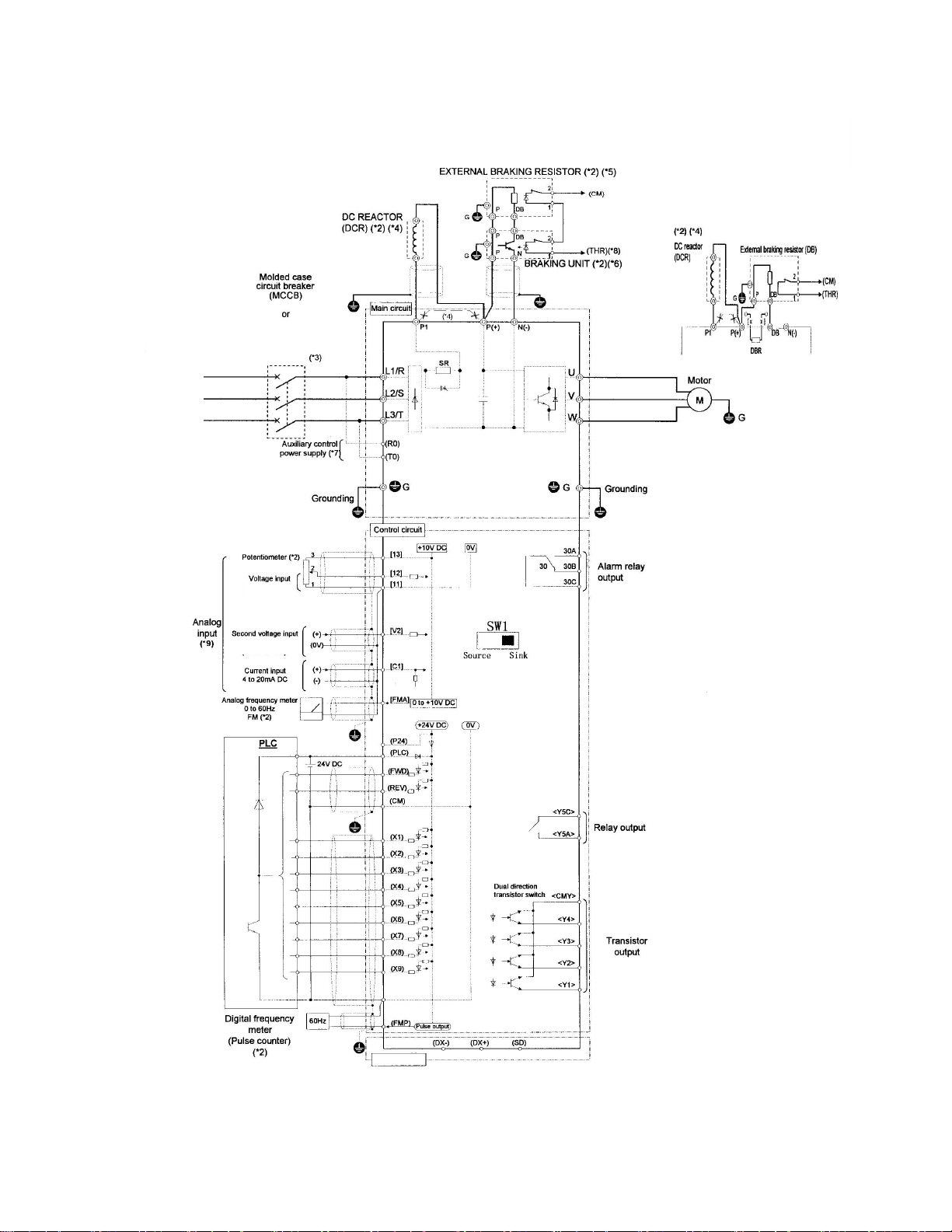
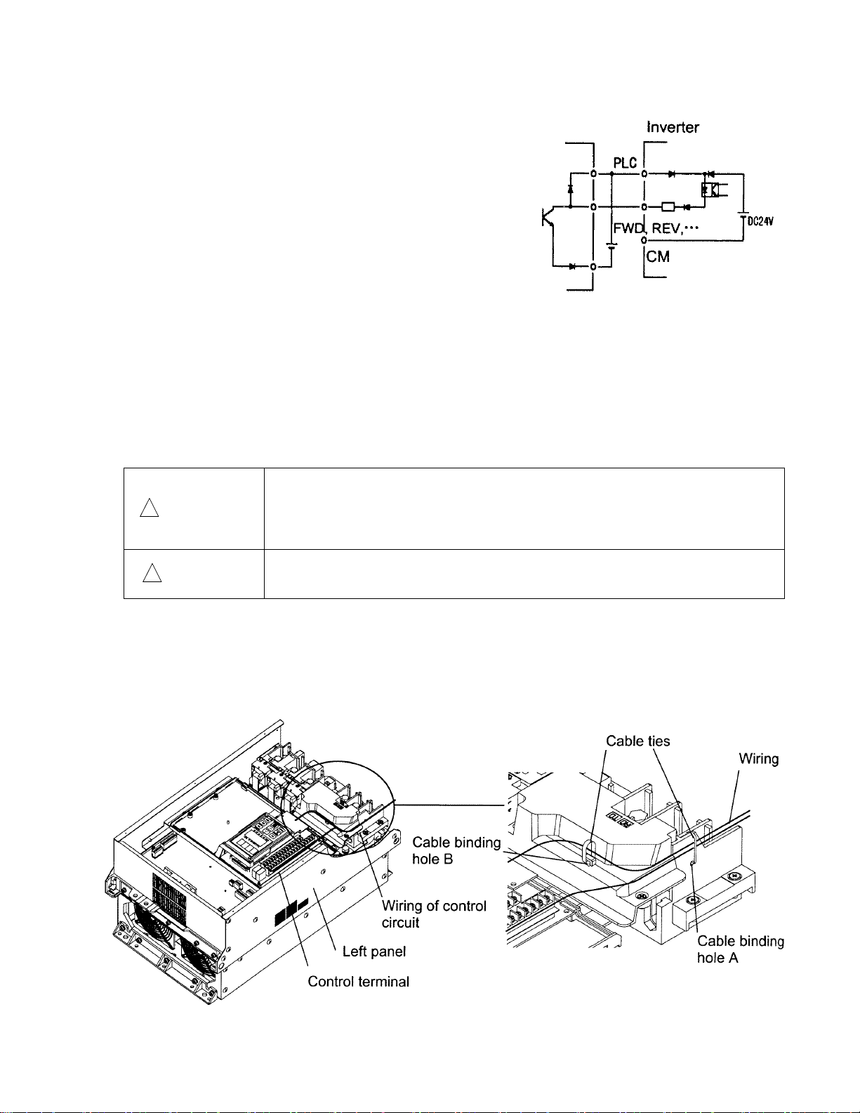
Basic Connection Diagram to PLC (Sink Logic)
Ground-faul t
circuit interrupter
(GFCI)
Please refer to
9.1
Standard
specifications
for detail.
G11S:15HP and above
P11S:20HP and above
G11S:Up to 10HP
P11S:Up to 15HP
(*10)
0 to +/- 10V
0 to 10V
RS-485
Fig.2-3-2
2-5
Page 20
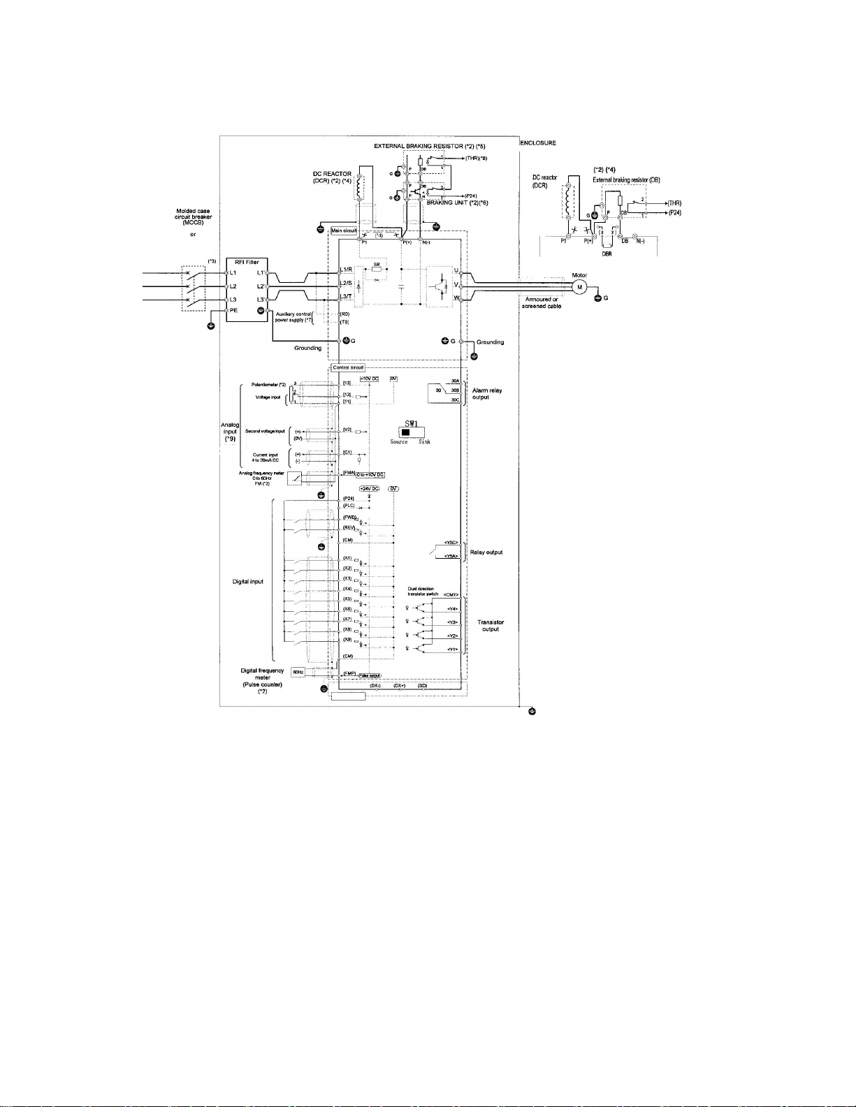
Basic Connection Diagram (Source Logic, Typically used in Europe)
Please refer to
specifications
9.1
Standard
for detail.
Ground-faul t
circuit interrupter
(GFCI)
0 to +/- 10V
0 to 10V
G11S:15HP and above
P11S:20HP and above
G11S:Up to 10HP
P11S:Up to 15HP
(*10)
RS-485
Fig.2-3-3
Note: The control circuit common terminals [11], (CM) and <CMY> are isolated
(*1) Use a drive with rated voltage matching the power supply voltage.
(*2) Use as required.
(*3) Use this peripheral device when necessary.
(*4) Remove the jumper wire (*4) between P1 and P(+) before connecting a DC REACTOR.
(*5) Be sure to use the braking unit (option)(*6) when connecting the external braking resistor (option)(*5)
(*6) Connect the braking unit to P(+) and N(-). The auxiliary terminals [1] and [2] have polarity.
Connect them as shown in the figure above.
(*7) The drive can be operated without connecting the auxiliary control power supply.
(*8) Terminal (X1) to (X9) can be set to 9 (THR) - Braking unit thermal trip input.
(*9) If using V2 or C1, as a reference signal, they must be used exclusively.
(*10) The P11S series inverter does not incorporate a DBR.
2-6
Page 21
Basic Connection Diagram to PLC (Source logic, Typically used in Europe)
Please refer to
9.1
Standard
specifications
for detail.
Ground-faul t
circuit interrupter
(GFCI)
0 to +/- 10V
G11S:15HP and above
P11S:20HP and above
G11S:Up to 10HP
P11S:Up to 15HP
(*10)
(THR)
(P24)
0 to 10V
RS-485
Fig.2-3-4
2-7
Page 22
2-3-2 Connecting the main circuit and ground terminals
Table 2-3-1 Functions of main circuit terminals and ground terminals
Symbol Terminal name Description
L1/R, L2/S, L3/T Main circuit power terminal Connects a 3-phase power supply.
U, V, W Inverter output terminal Connects a 3-phase motor.
R0, T0
P1, P (+)
P (+), DB
P (+), N (-) DC link circuit terminal
G Inverter ground terminal Grounds the inverter chassis (case) to the earth.
Auxiliary control-power
input terminal
DC reactor connecting
terminal
External braking resistor
connecting terminal
Connects a backup AC power supply to the
control circuit. (Not supported for inverter of 1HP
or less)
Connects the optional power-factor correcting DC
reactor.
Connects the optional external braking resistor.
(For models of 10HP or less for G11S, 15HP or
less for P11S)
Supplies DC link circuit voltage to the external
braking unit (option) or power regeneration unit
(option).
(1) Main circuit power terminals (L1/R, L2/S, L3/T)
① Connect these terminals to the power supply via a molded-case circuit breaker or a ground-fault circuit
interrupter for circuit (wiring) protection. Phase-sequence matching is unnecessary.
② To ensure safety, a magnetic contactor should be connected to disconnect the inverter from the power
supply when the inverter protective function activates.
③ Use control circuit terminal FWD/REV or the RUN/STOP key on the keypad panel to start or stop the
inverter. The main circuit power should be used to start or stop the inverter only if absolutely necessary
and then should not be used more than once every hour.
④ If you need to connect these terminals to a single-phase power supply, please contact the factory.
(2) Inverter output terminals (U, V, W)
① Connect these terminals to a 3-phase motor in the correct phase sequence. If the direction of motor
rotation is incorrect, exchange any two of the U, V, and W phases.
② Do not connect a power factor correction capacitor or surge absorber to the inverter output.
③ If the cable from the inverter to the motor is very long, a high-frequency current may be generated by stray
capacitance between the cables and result in an overcurrent trip of the inverter, an increase in leakage
current, or a reduction in current indication precision.
When a motor is driven by a PWM-type drive, the motor terminals may be subject to surge voltage generated
by drive element switching. If the motor cable (with 460V series motors, in particular) is particularly long,
surge voltage will deteriorate motor insulation. To prevent this, use the following guidelines:
Inverters 7.5 HP and larger
Motor Insulation Level 1000V 1300V 1600V
460 VAC Input Voltage 66 ft (20 m) 328 ft (100 m) 1312 ft (400 m) *
230 VAC Input Voltage 1312 ft (400 m) * 1312 ft (400 m) * 1312 ft (400 m) *
Inverters 5 HP and smaller
Motor Insulation Level 1000V 1300V 1600V
460 VAC Input Voltage 66 ft (20 m) 165 ft (50 m) * 165 ft (50 m) *
230 VAC Input Voltage 328 ft (100 m) * 328 ft (100 m) * 328 ft (100 m) *
* For this case the cable length is determined by secondary effects and not voltage spiking.
Note: When a motor protective thermal O/L relay is inserted between the inverter and the motor, the thermal
O/L relay may malfunction (particularly in the 460V series), even when the cable length is 165 feet (50m) or
less. To correct, insert a filter or reduce the carrier frequency. (Use function code “F26 Motor sound”.)
2-8
Page 23
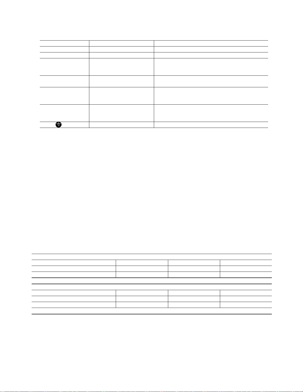
(3) Auxiliary control-power input terminals (R0 and T0)
The inverter operates even if power is not
provided to these terminals.
If a protective circuit operates and the
magnetic contactor on the inverter power
side is opened (off), the inverter control circuit
power, the alarm output (30A, B, and C), and
Power supply
RCD
Noise filter
Magnetic
contactor
Inverter
L1/R
L2/S
L3/T
P1
P(+)
+
the keypad panel display goes off. To prevent
this, the same AC power as the main circuit
AC power must be supplied (as auxiliary
control power) to the auxiliary control-power
input terminals (R0 and T0).
① To ensure effective noise reduction when
Insulation Transformer
R0
T0
+
DC/DC
Inverter
control power
using a radio noise filter, the output power
from the filter must go to the auxiliary
control-power input terminals.
If these terminals are connected to the input side of the filter, the noise reduction effect deteriorates.
Fig. 2-3-5 Connecting the auxiliary control-power input terminals
② When the RCD (Residual-current Protective Device) is installed (G11S:30HP or less), the terminal R0 and
T0 should be connected to the OUTPUT side of the RCD. If they are connected to the input side of the
RCD, RCD will be malfunction because the power supply of the inverter is three phase and the terminal R0
and T0 is single phase.
When the terminal R0 and T0 are connected to the INPUT side of the
RCD, the insulation transformer is required to install as shown on the
Fig. 2-3-5.
(4) DC reactor connecting terminals (P1 and P (+))
① Before connecting a power-factor correcting DC reactor (optional) to
these terminals, remove the factory-installed jumper.
② If a DC reactor is not used, do not remove the jumper.
Note:For inverter of 100HP or more, the DC reactor is provided as a separate
standard component and should always be connected to the terminals.
Fig. 2-3-6
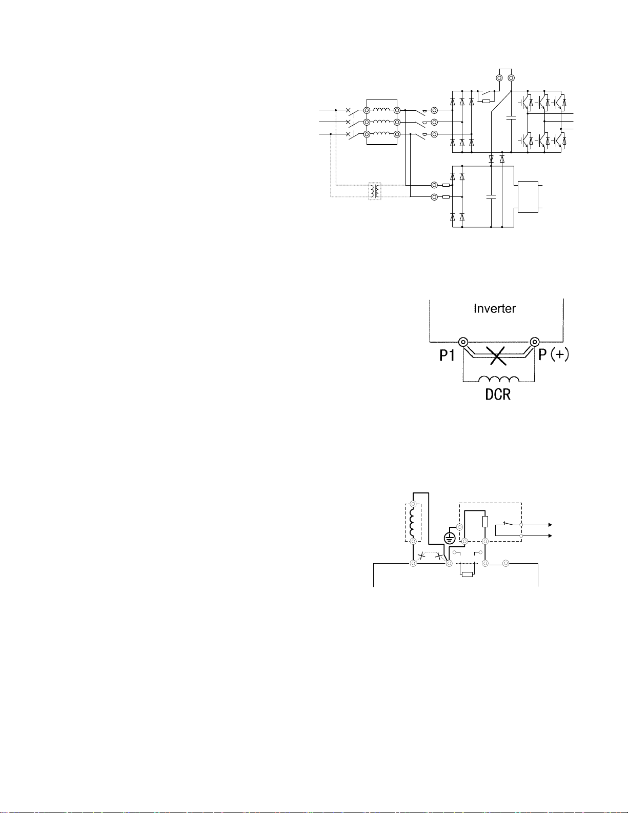
(5) External braking-resistor connecting terminals (P (+) and DB)
For the G11S of 10HP or less, a built-in braking resistor is connected to terminals P (+) and DB. For the P11S
of 15HP or less, no built-in braking resister is connected, however built-in braking transistor is equipped. If
this braking resistor does not provide sufficient thermal capacity (e.g., in highly repetitive operation or
heavy inertia load operation) or braking torque is not enough, an external braking resistor (option) must be
mounted to improve braking performance.
① In case of G11S, remove the built-in braking resistor
from terminals P(+) and DB. Insulate the
resistor-removed terminals with adhesive insulation
tape, etc.
② Connect terminals P(+) and DB of the external braking
resistor to terminals P(+) and DB of the inverter.
③ The wiring (cables twisted or otherwise) should not
exceed 16ft (5m).
DC reactor
(DCR)
P1 P(+)
External braking resistor (DB)
2
PDB
[ x x ]
DBR
1
DB N(-)
Fig. 2-3-7 Connection (G11S:10HP or less)
(THR)
(P24)
2-9
Page 24
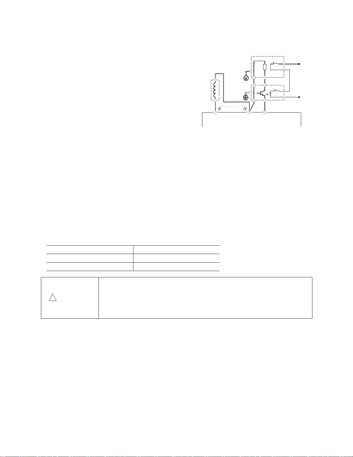
(6) DC link circuit terminals (P (+) and N (-))
The models of 15HP or above for G11S, 20HP or above for P11S does not contain a drive circuit for the
braking resistor. To improve braking performance,
an external braking unit (option) and an external
braking resistor (option) must be installed.
① Connect terminals P(+) and N(-) of the braking unit
to terminals P(+) and N(-) of the inverter. The
wiring (cables twisted or otherwise) should not
exceed 16ft(5m).
② Connect terminals P(+) and DB of the braking
resistor to terminals P(+) and DB of the braking unit.
The wiring (cables twisted or otherwise) should not
exceed 33ft (10m). When terminals P (+) and N (-)
of the inverter are not used, leave terminals open.
DC reactor
(DCR)
P1 P(+) N(-)
External braking resistor (DB)
2
1
DB
P
P
DB
2
P
N
1
Braking unit (BU)
If P (+) is connected to N (-) or the braking resistor
is connected directly, the resistor will break.
③ Auxiliary contacts 1 and 2 of the braking unit have
polarity. To connect the power regeneration unit, refer
to the "Power Regeneration Unit Instruction Manual".
Fig. 2-3-8 Connection (G11S:10HP or above, P11S:15HP
or above)
(7) Inverter ground terminal
To ensure safety and noise reduction, always ground the inverter ground terminal. Also, metal frames of
electrical equipment must be grounded as specified in the Electric Facility Technical Standard.
The connection procedure is as follows:
① Ground metal frames to a ground terminal (Ground resistance:10Ω or less).
② Use a suitable cable (short and thick) to connect the inverter system to the ground terminal.
(THR)
(P24)
(8) Auxiliary power switching connector (CN UX) (for inverter of 40HP or more)
When an inverter of 40HP or more requires a main circuit power voltage as listed in Table 2-3-2, disconnect
auxiliary power switching connector CN UX from U1 and connect to U2. For the switching method, see Fig.
2-3-11.
Table 2-3-2 Main circuit power voltage requiring auxiliary power switching connector switching
Frequency [Hz] Power voltage range [VAC]
50 380-398
60 380-430
• Check that the number of phases and rated voltage of this product match
those of the AC power supply.
!
CAUTION
• Do not connect the AC power supply to the output terminals (U, V, W).
Injury may result.
• Do not connect a braking resistor directly to the DC terminals (P[+] and N[-]).
Fire may result.
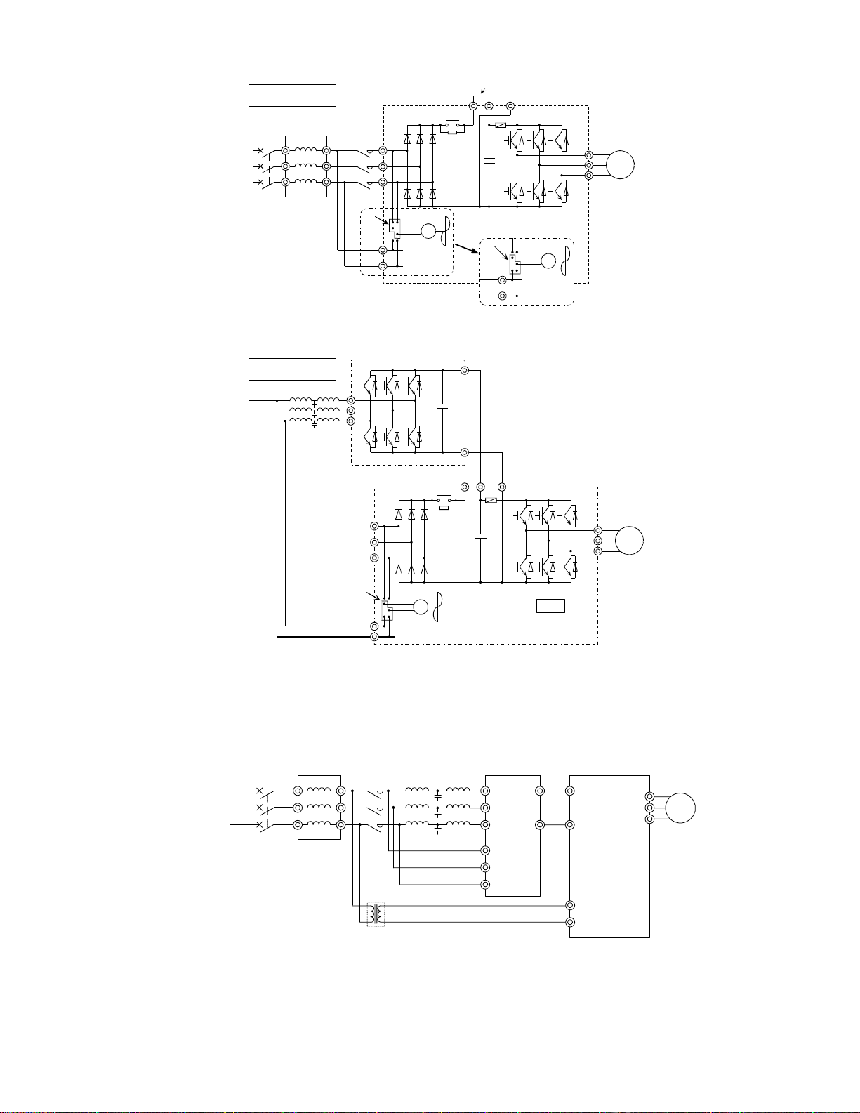
(9) Fan power switching connector (CN RXTX) (for inverter of 40HP or more)
G11S/P11S without options supports DC power input via DC common connection by connecting the power
regeneration converter (RHC series) as shown in Fig. 2-3-10.
For details, refer to technical documentation.
The inverter of 40HP or more contains an AC-powered component (e.g., AC cooling fan).
To use the inverter using DC power input, switch the fan power switching connector (CN RTXT) inside the
inverter to the R0-T0 side and provide AC power to the R0 and T0 terminals. (See Fig. 2-3-9.)
For the switching method, see Fig. 2-3-11.
Note:
In the standard state, the fan power switching connector (CN RXTX) is connected to the L1/R-L3/T side.
When DC power input is not used, do not switch this connector.
The same AC voltage as the main circuit power voltage must be supplied to the auxiliary control-power input terminals
(R0 and T0). If not supplied, the fan does not rotate and the inverter will overheat (0H1).
2-10
Page 25
P
30kW or more
40HP or more
Noise filter
MCCB
Magnetic
contactor
Jumper (not supplied for inverter of 100HP or more)
Jumper (not supplied for inverter of 75kW or more)
P(+)
N(-)
Invert er
L1/R
L2/S
L3/T
P1
F
+
C
U
V
M
W
Power supply
CN RX TX
R0
T0
Fan
CN RX TX
R0
T0
When switched to DC power input mode
Fig. 2-3-9 Fan power switching
40HP or more
30kW or more
Power supply
PWM converter
R
S
T
Inverter
L1/R
L2/S
L3/T
CN RX TX
R0
T0
P(+)
C
+
N(-)
P(+)
P1
F
C
+
Fan
Switch CNRXTX to the R0-T0 side.
N(-)
U
V
W
M
Fig. 2-3-10A Example of connection by combination with power regeneration converter(40HP or more)
Note:
To connect the power regeneration converter to an inverter of 30HP or less, do not connect the power supply directly to the auxiliary control-power input
terminals (R0 and T0) of the inverter. However, if such a connection is required, insulate these input terminals from the main power of the power
regeneration converter with an insulation transformer. The connection example of a power regeneration unit is provided in the "Power Regeneration
Unit Instruction Manual".
MCCB or RCD
ower supply
Noise filter
Magnetic
contactor
Insulation Transformer
RHC series
L1/R
L2/S
L3/T
R1
S1
T1
L1/R
L3/T
R0
T0
FRN-G11S
U
V
M
W
Fig. 2-3-10B Example of connection by combination with power regeneration converter (30HP or less)
2-11
Page 26
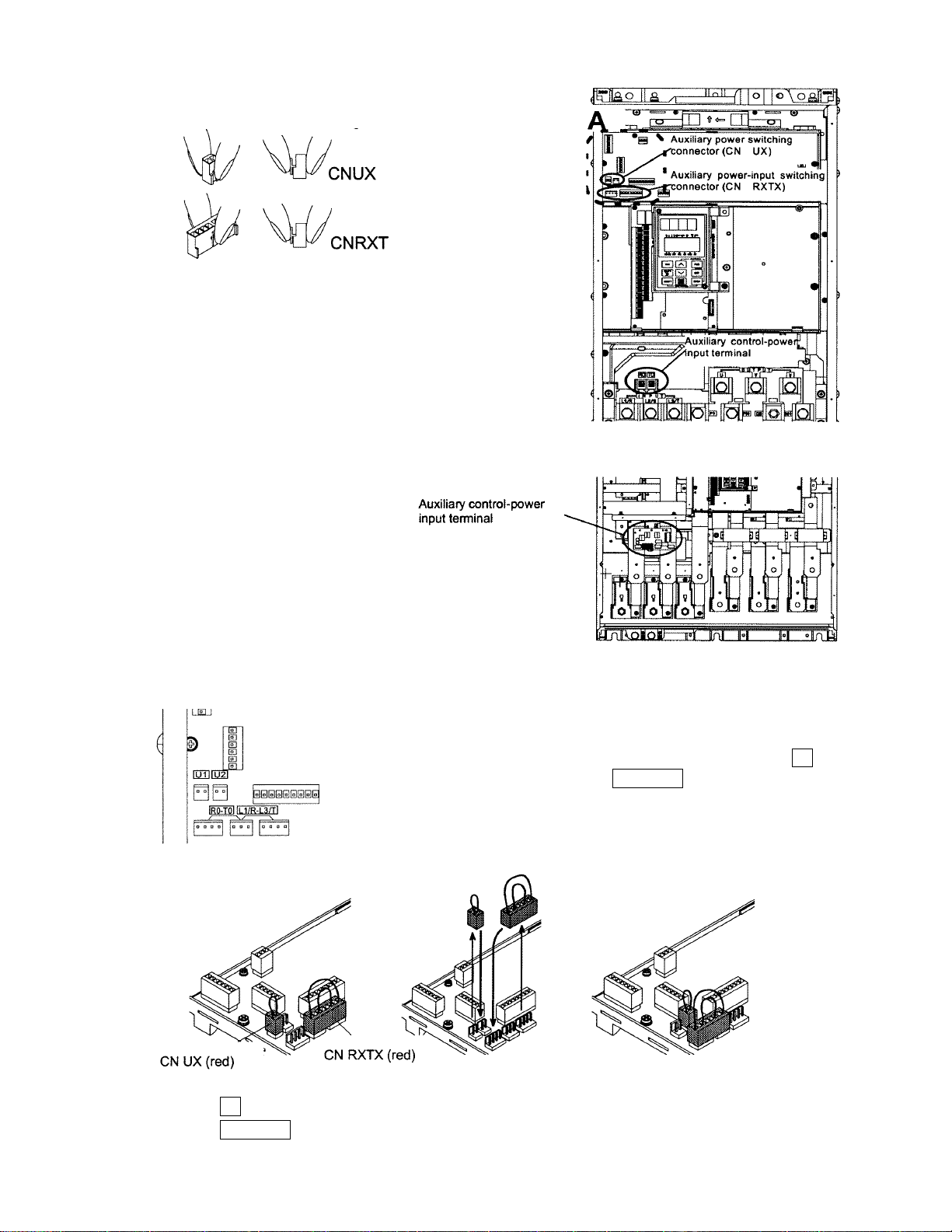
The switching connectors are mounted on the power
PCB above the control PCB as shown on the right.
Note:
To remove a connector, unlock the connector (using
the locking mechanism) and pull. To mount a
connector, push the connector until it click locks.
FRN040 to 075G11S-2UX, FRN040 to 150G11S-4UX,
FRN040 to 100P11S-2UX, FRN040 to 200P11S-4UX
FRN100 to 125G11S-2UX, FRN200 to 600G11S-4UX,
<Enlarged view of part A>
FRN125 to 150P11S-2UX, FRN250 to 800P11S-4UX
When shipped from the factory, CN UX is connected to the U1 side
and CN RXTX is connected to the L1/R-L3/T side.
<Oblique view of part A>
Factory shipment status Connector removal After connector switching.
CNUX : U1
CNRXTX : L1/R-L3/T
Fig. 2-3-11 Power switching connectors (only for 40HP or more)
In this figure the power voltage is 380 to 398V AC, 50Hz (or 380 to
430V AC, 60Hz) and the inverter is used in DC power input mode.
2-12
Page 27
2-3-3 Connecting the control terminals
Table 2-3-3 lists the functions of the control circuit terminals. A control circuit terminal should be connected
according to the setting of its functions.
Table 2-3-3
Classification
Analog input
Digital input
Terminal
symbol
13 Potentiometer power
12 Voltage input ① Frequency is set according to the analog input voltage supplied from
V2 Voltage input Frequency is set according to the analog input voltage supplied from an
C1 Current input ① Frequency is set according to the analog input current supplied from
11 Analog input common Common terminal for analog input signals
FWD Forward operation/stop
REV Reverse operation/stop
X1 Digital input 1
X2 Digital input 2
X3 Digital input 3
X4 Digital input 4
X5 Digital input 5
X6 Digital input 6
X7 Digital input 7
X8 Digital input 8
X9 Digital input 9
Terminal name Function
supply
command
command
Used for +10V DC power supply for frequency setting POT (variable
resistor of 1 to 5kΩ)
an external circuit.
- 0 to +10V DC/0 to 100%
- Reversible operation using positive and negative signals:0 to +/10V DC/0 to 100%
- Reverse operation: +10 to 0V DC/0 to 100%
② The feedback signal for PID control is input.
③ The analog input value from the external circuit is used for torque
control. (P11S does not support this function.)
* Input resistance: 22kΩ
external circuit
- 0 to +10V DC/0 to 100%
- Reverse operation:+10 to 0V DC/0 to 100%
* It can be used only one terminal "V2" or "C1" alternatively
* Input resistance:22kΩ
an external circuit.
- 4 to 20mA DC/0 to 100%
- Reverse operation:20 to 4mA DC/0 to 100%
② The feedback signal for PID control is input.
③ PTC thermistor input
* It can be used only one terminal "V2" or "C1" alternatively.
* Input resistance:250Ω
Used for forward operation (when FWD-CM is on) or deceleration and
stop (when FWD-CM is off)
Used for reverse operation (when REV-CM is on) or deceleration and
stop (when REV-CM is off)
The coast-to-stop command, external alarm, alarm reset, multistep
frequency selection, and other functions (from an external circuit) can be
assigned to terminals X1 to X9. For details, see "Setting the Terminal
Functions E01 to E09" in Section 5.2, "Details of Each Function."
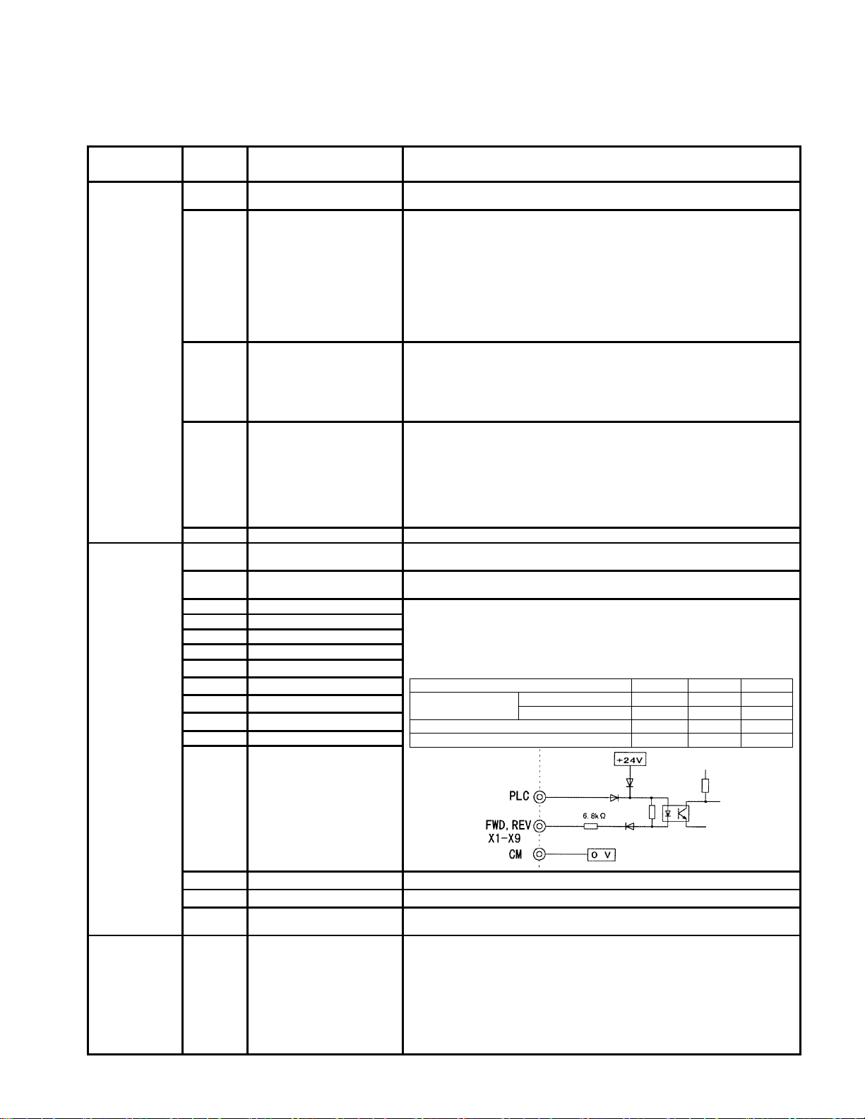
<Specifications of digital input circuit>
*
Item min. typ. max.
ON level 0V - 2V Operating voltage
OFF level 22V 24V 27V
Operating current at ON level - 3.2mA 4.5mA
Allowable leakage current at OFF level - - 0.5mA
Analog output
CM Common terminal Common terminal for Digital input and FMP terminals
P24 Control Unit power Supply +24VDC power supply for control input. Maximum output current 100mA
PLC PLC signal power Used to connect power supply for PLC output signals (rated voltage
FMA
(11:
Common
terminal)
Analog monitor Outputs monitor signal using analog DC voltage 0 to +10V DC.
24(22 to 27) V DC) at source logic operation.
The meaning of this signal is one of the following:
-Output frequency (before slip compensation) -Power consumption
-Output frequency (after slip compensation) -PID feedback value
-Output current -PG feedback value
-Output voltage -DC link circuit voltage
-Output torque -Universal AO
-Load factor
*Connectable impedance:5kΩ minimum
2-13
Page 28
Pulse output
Transistor
output
FMP
(CM:
Common
terminal)
Y1 Transistor output1
Y2 Transistor output2
Y3 Transistor output3
Y4 Transistor output4
Frequency monitor
(pulse waveform output)
Outputs a monitor signal using the pulse waveform.
This signal has the same function as the FMA signal.
A running signal, frequency equivalence signal, overload early warning
signal, and other signals from the inverter are output (as transistor
output) to arbitrary ports, For details, see "Setting the Terminal
Functions E20 to E23" in Section 5.2, "Details of Each Function."
*
voltage
Maximum load current at ON level - - 50mA
Leakage current at OFF level - - 0.1mA
<Specifications of transistor output circuit>
Item min. typ. max.
ON level - 2V 3V Operating
OFF level - 24V 27V
Relay output
Communication
CMY Transistor output
30A,30B,
30C
Y5A,Y5C Multipurpose-signal relay
DX+, DX- RS-485 communication
SD Communication-cable
common
Alarm output for any fault If the inverter is stopped by an alarm (protective function), the alarm
output
input-output
shield connection terminal
Common terminal for transistor output signals
This terminal is insulated from terminals [CM] and [11].
signal is output from the relay contact output terminal (1SPDT).
Contact rating: 48V DC, 0.5A
An excitation mode (excitation at alarm occurrence or at normal
operation) can be selected.
These signals can be output similar to the Y1 to Y4 signals above.
The contact rating for any fault is the same as that of the alarm output
above.
An excitation mode (excitation at alarm occurrence or at normal
operation) can be selected.
Input-output signal terminals for RS-485 communication. UP to 31
inverters can be connected using the daisy chain method.
Terminal for connecting the shield of a cable. The terminal is
electrically floating.
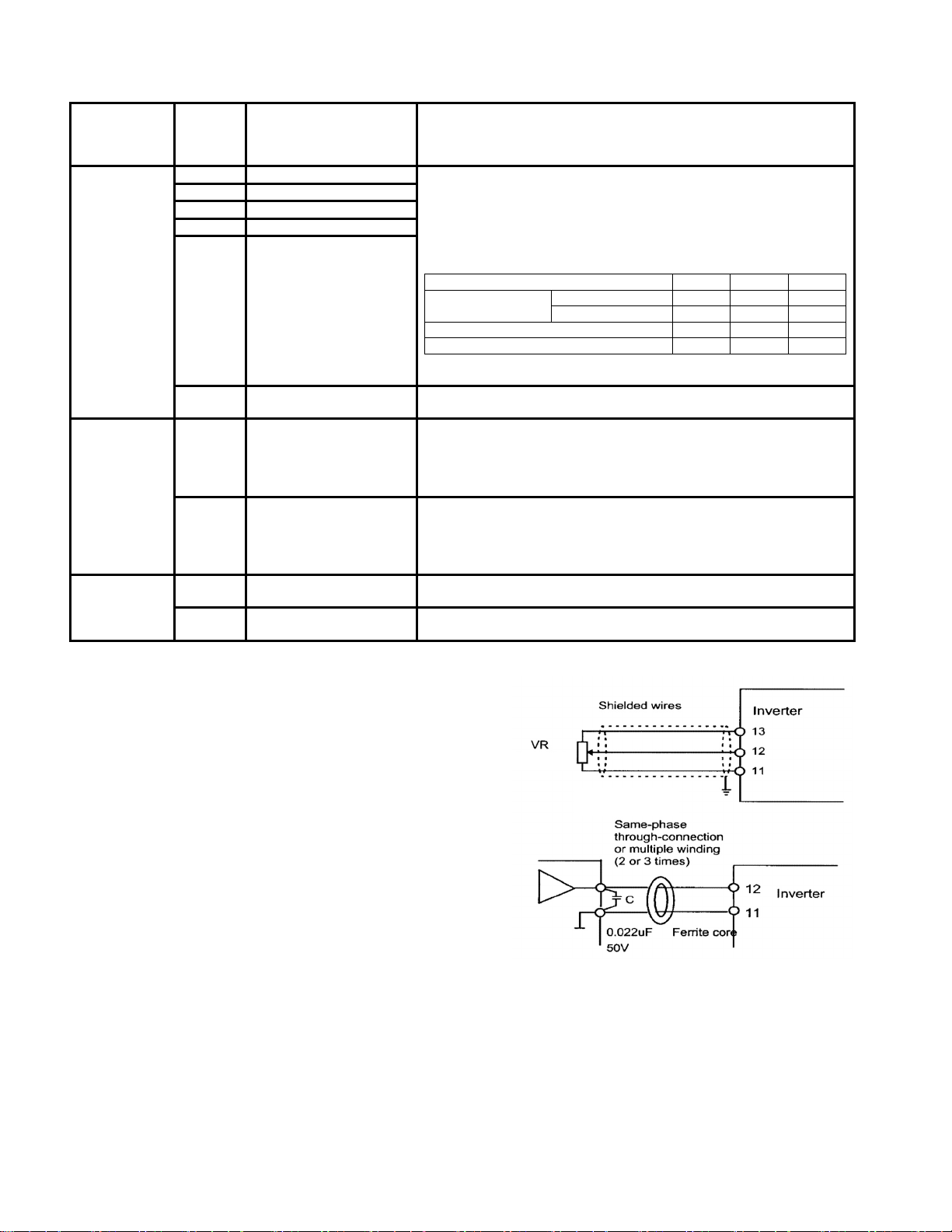
(1)Analog input terminals (13,12,V2,C1,and 11)
①These terminals receive weak analog signals that may be
affected by external noise. The cables must be as short as
possible (66ft (20m) or less), must be shielded, and must
be grounded in principle. If the cables are affected by
external induction noise, the shielding effect may be
improved by connecting the shield to terminal [11].
② If contacts must be connected to these circuits, twin
(bifurcated type) contacts for handling weak signals must
be used. A contact must not be connected to terminal
[11].
③If an external analog signal output device is connected to
these terminals, it may malfunction as a result of inverter
noise. To prevent malfunction, connect a ferrite core or
capacitor to the external analog signal output device.
0k to 5 kΩ
Fig. 2-3-12
Fig. 2-3-13 Example of noise prevention
2-14
Page 29
r
(2) Digital input terminals (FWD, REV, X1 to X9 and CM)
① Digital input terminals (e.g., FWD, REV, X1 to X9)
are generally turned on or off by connecting or
disconnecting the line to or from the CM terminal. If
Digital input terminals are turned on or off by
switching the open collector output of PLC using an
external power supply, a resulting bypass circuit may
cause the inverter to malfunction.
To prevent a malfunction, connect the PLC terminal
as shown in Fig. 2-3-14.
② When using a contact input, a relay having highly
reliable contact must be used.
Programmable
Logic controller
Fig. 2-3-14
Connection for External power supply
(3) Transistor output terminals (Y1 to Y4, CMY)
① To connect a control relay, connect a surge absorbing diode to both ends of its exciting coil.
(4) Others
① To prevent a malfunction as a result of noise, control terminal cables must be placed as far as possible
from the main circuit cables.
② The control cables inside the inverter must be secured to prevent direct contact with live section (e.g.,
main-circuit terminal block) of the main circuit.
Control lines generally do not have enhanced insulation. If the insulation of a
control line is damaged, the control signals may be exposed to high voltage in the
!
WARNING
main circuit. The Low Voltage Directive in Europe also restricts the exposure to
high voltage.
Electric shock may result
The inverter, motor, and cables generate noise.
!
CAUTION
Check that the ambient sensors and devices do not malfunction.
Accident may result.
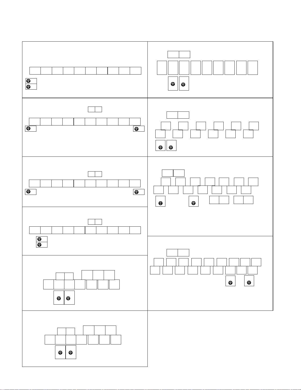
(5) Wiring of control circuit (inverter of 40HP or more)
① Pull out the control circuit wiring along the left panel as shown in Fig. 2-3-15.
② Secure the cable to cable binding hole A (on the left wall of the main circuit terminal block) using a cable-tie
(e.g., insulock). The cable-tie must not exceed 0.14inch (3.5mm) in width and 0.06inch (1.5mm) in
thickness.
③ When the optional PC board is mounted, the signal lines must be secured to cable binding hole B.
Fig. 2-3-15 The wiring route of the control circuit
2-15
Fig. 2-3-16 The securing positions of the
control-circuit line of inverte
(40HP or more)
Page 30
2-3-4 Terminal arrangement
(1) Main circuit terminals
FRNF25 to 001G11S-2UX
FRNF50 to 001G11S-4UX Screw size M3.5
FRN100G11S-2UX /FRN125P11S-2UX
Screw size M4
T0R0
L2/S L1/R DB L3/T P(+) P1 U N(-) WV
G
G
Screw size M3.5
L3/TL2/SL1/R
GG
GG
N(-)
P(+)
P1
Screw size G: M10
Screw size G: M10
other terminals : M12
other terminals : M12
Max. lug width 0.29inch (7.4mm) Max. lug width 1.38inch (35mm)
FRN002 to 005G11S-2UX
FRN002 to 005G11S-4UX
Screw size M3.5
T0 R0
L2/S L1/R DB L3/T P(+) P1 U N(-) WV
Screw size M4
Max. lug width 0.40inch (10.1mm)
FRN007 to 010G11S-2UX /FRN007 to 015P11S-2UX
FRN007 to 010G11S-4UX /FRN007 to 015P11S-4UX
T0 R0
Screw size M3.5
L2/S L1/R DB L3/T P(+) P1 U N(-) WV
Screw size M5
Max. lug width 0.53inch (13.5mm)
FRN125G11S-2UX /FRN150P11S-2UX
FRN200 to 350G11S-4UX /FRN250 to 450P11S-4UX
Screw size M4
G G
L1/R L2/S L3/T
T0R0
P1 U P(+)
GG
Screw size G : M10
other terminals : M12
Max. lug width 1.26inch (32mm)
FRN400, 450 G11S-4UX/FRN500, 600 P11S-4UX
G G
L1/R L2/S
G
T0R0
L1/R L2/S
Screw size M4
L3/T
L3/T
P1
G
P1
U V W
P(+) P(+)
FRN015 to 030G11S-2UX /FRN020 to 030P11S-2UX
FRN015 to 030G11S-4UX /FRN020 to 030P11S-4UX
L2/S L1/R DB L3/T P(+) P1 U N(-) WV
G
Screw size M6
G
T0 R0
Screw size M3.5
Max. lug width 0.72inch (18.25mm)
FRN040G11S-2UX /FRN040 to 050P11S-2UX
FRN040 to 075G11S-4UX /FRN040 to 100P11S-4UX
Screw size M4
R0 T0
L3/T L2/S L1/R
G
G
P1
Screw size M8
W V U
N(-) P(+)
Max. lug width 1.18inch (30mm)
FRN050 to 075G11S-2UX /FRN060 to 100P11S-2UX
Max. lug width 1.26inch (32mm)
FRN500, 600 G11S-4UX/FRN700, 800 P11S-4UX
T0R0
L1/R L2/S L3/T
L1/R L2/S L3/T
P1 P(+)
P1
Screw size R0, T0 = M4 G = M10
Other terminals = M12
Max. lug width 1.26inch (32mm)
Screw size G = M10
Other terminals = M12
N(-)
P(+)
N(-) U U
FRN100 to 150G11S-4UX /FRN125 to 200P11S-4UX
Screw size M4
R0 T0
W V U
U
WV
W
V N(-)
U V W
N(-)N(-)
VVW
W
G
G
L3/T L2/S L1/R
P1
G
G
Screw size G : M8
other terminals : M10
Max. lug width 1.38inch (35mm)
N(-) P(+)
2-16
Page 31
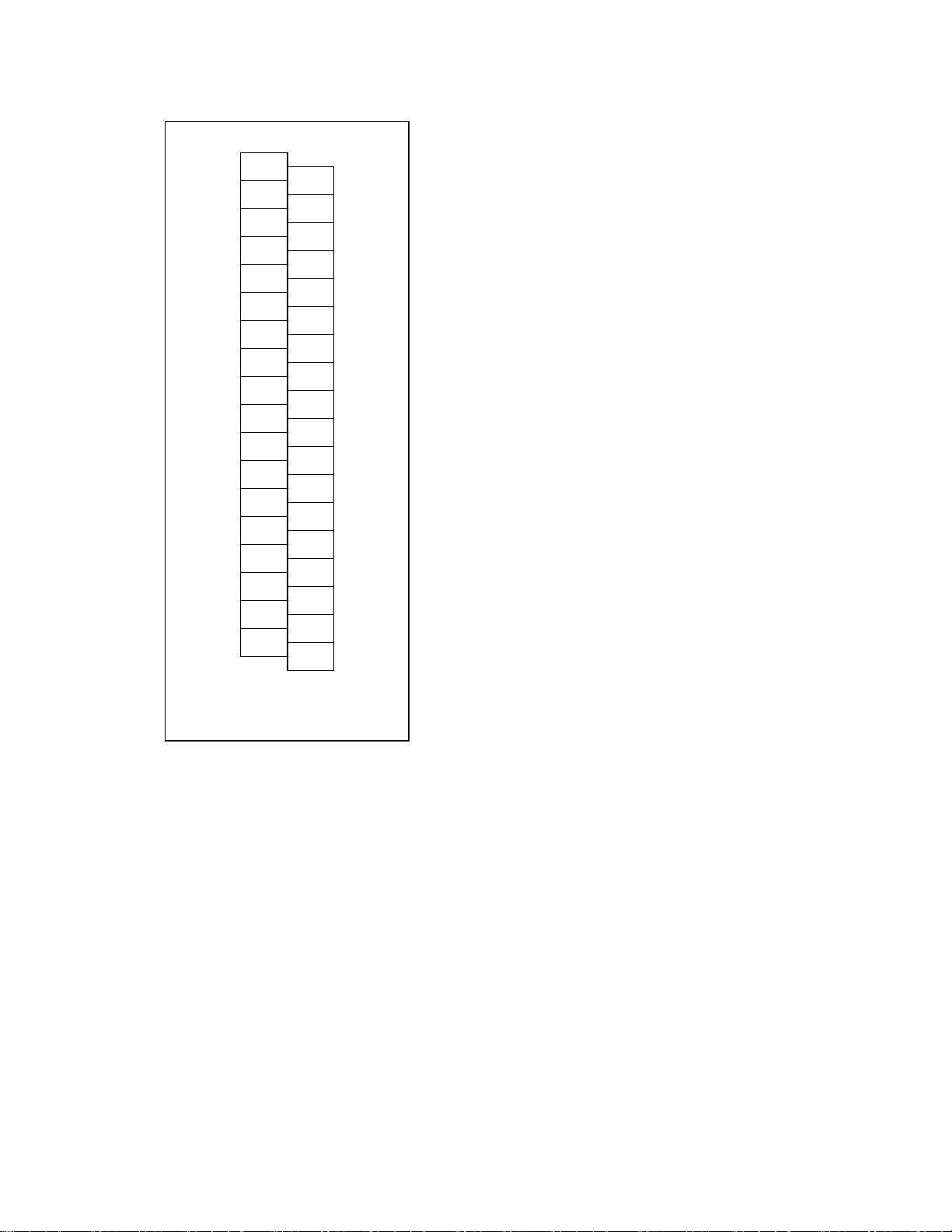
(2) Control circuit terminals
30C
30A
30B
Y5A
Y5C
CMY
Y4
Y3
Y2
Y1
11
C1
12
FMA
13
FMP
V2
PLC
CM
X1
CM
X2
FWD
X3
REV
X4
P24
X5
P24
X6
DX −
X7
DX +
X8
SD
X9
2-17
Page 32

2-3-5 Applicable equipment and wire size for main circuit
MCCB or
Voltage
Inverter type
G11S/P11S
FRNF25G11S-2UX 5 5
FRNF50G11S-2UX 5 5
FRN001G11S-2UX 5 10
FRN002G11S-2UX 10 15
FRN003G11S-2UX 10 20 14 (2.1)
FRN005G11S-2UX 20 30
FRN007G11S-2UX
FRN007,010P11S-2UX
FRN010G11S-2UX
FRN015P11S-2UX
FRN015G11S-2UX
FRN020P11S-2UX
3-phase
230V
3-phase
460V
Note:The type of wire is 70℃(149ºF) 600V Grade heat-resistant polyvinyl chloride insulated wires (PVC).
FRN020G11S-2UX
FRN025P11S-2UX
FRN025G11S-2UX
FRN030P11S-2UX
FRN030G11S-2UX 100 175
FRN040G11S/P11S-2UX 150 200
FRN050P11S-2UX
FRN050G11S-2UX
FRN060G11S/P11S-2UX 200 300 3/0 (85.0)
FRN075G11S/P11S-2UX 250 350 4/0 (107.2)
FRN100P11S-2UX
FRN100G11S-2UX
FRN125P11S-2UX 2/0X2 (67.4X2)
FRN125G11S -2UX
FRN150P11S-2UX 500 FRNF50G11S-4UX 5 5
FRN001G11S-4UX 5 5
FRN002G11S-4UX 5 10
FRN003G11S-4UX 5 15
FRN005G11S-4UX 10 20
FRN007G11S-4UX
FRN007, 010P11S-4UX
FRN010G11S-4UX
FRN015P11S-4UX
FRN015G11S-4UX
FRN020P11S-4UX
FRN020G11S-4UX
FRN025P11S-4UX
FRN025G11S-4UX
FRN030P11S-4UX
FRN030G11S-4UX 50 100
FRN040G11S/P11S-4UX 75 125
FRN050G11S/P11S-4UX 100 125
FRN060G11S/P11S-4UX 100 150 3 (26.7)
FRN075G11S/P11S-4UX 125 200 2 (33.6)
FRN100P11S-4UX
FRN100G11S-4UX
FRN125G11S/P11S-4UX 200 - 2/0 (67.4)
FRN150G11S/P11S-4UX 250 - 4/0 (107.2)
FRN200P11S-4UX
FRN200G11S-4UX
FRN250G11S/P11S-4UX 350 - 350(177)
FRN300P11S-4UX
FRN300G11S-4UX
FRN350G11S/P11S-4UX 500 FRN400G11S/P11S-4UX
FRN450P11S-4UX
FRN450G11S-4UX 700 FRN500G11S/P11S-4UX 800 - 500X2(253X2)
FRN600G11S/P11S-4UX 1,000 - 600X2(304X2)
FRN700P11S-4UX 1,000 - 500X3(253X3)
FRN800P11S-4UX 1,200 -
The above-mentioned wire size are the recommended size under the condition of the ambient temperature 50℃(122ºF) or lower.
RCD/GFCI
Rated current(A)
W/
DCR
30 50
30,40 50,75
40 75
50 100
50 100
75 125
75 125
100 150
100 150
100 175
175 250 1/0 (53.5)
350 -
400 -
15 30
15,20 30,40
20 40
30 50
30 50
40 60
40 60
40 75
40 75
50 100
175 - 1/0 (53.5)
300 -
500 -
600 - 300X2(152X2)
700 -
Required torque [lb-inch](N.m)
W/o
DCR
Main
terminal
10.6(1.2) - -
15.9(1.8)
31.0(3.5)
51.3(5.8)
119(13.5)
239(27)
425(48)
10.6(1.2) - -
15.9(1.8)
31.0(3.5)
51.3(5.8)
119(13.5)
239(27)
425(48)
Auxiliary
control-power
10.6(1.2)
10.6(1.2)
Control
6.2(0.7)
6.2(0.7)
L1/R,L2/S,L3/T
U,V,W
Wire range [AWG] (mm2)
16 (1.3)
10 (5.3)
8 (8.4)
6 (13.3)
4 (21.2)
3 (26.7)
2 (33.6)
1 (42.4)
1/0X2 (53.5X2)
350(177)
500(253)
300X2 (152X2)
16 (1.3)
14 (2.1)
12 (3.3)
10 (5.3)
8 (8.4)
6 (13.3)
4 (21.2)
1X2 (42.4X2)
250 (127)
600(304)
350X2(177X2)
600X3(304X3)
Auxiliary
control-power
16(1.3)
16(1.3)
Control
24 (0.2)
24 (0.2)
2-18
Page 33

A
CAUTION on Magnetic contactor selection (without DCR)
[without DCR]
The magnetic contactor should be selected from "Magnetic contactor models" shown in table 2-3-4 to
prevent the welding the magnetic contactor when using the auxiliary power input (R0, T0) and the time
between the magnetic contactor of the main circuit (L1/R, L2/S, L3/T) is OFF and re-turning on is "T off
main circuit re-turning on time" or the less shown in table 2-3-4.
[with DCR or other conditions]
When the inverter which is NOT described in the table 2-3-4 or using with DCR (power-factor
correcting DC reactor), the magnetic contactor is selected from "2-3-5 Applicable equipment and wire
size for main circuit" in chapter 2.
Table 2-3-4 Re-turning on time
*1 T off
Voltage G11S P11S
FRN002G11S-2UX
-
3-Phase
230V series
FRN003G11S-2UX
FRN005G11S-2UX
FRN007G11S-2UX FRN007P11S-2UX
FRN010G11S-2UX FRN010P11S-2UX
FRN015G11S-2UX FRN015P11S-2UX
3-Phase
460V series
FRN002G11S-4UX
FRN003G11S-4UX
FRN005G11S-4UX
FRN007G11S-4UX FRN007P11S-4UX
FRN010G11S-4UX FRN010P11S-4UX
FRN015G11S-4UX FRN015P11S-4UX
FRN020G11S-4UX FRN020P11S-4UX
FRN025G11S-4UX FRN025P11S-4UX
FRN030G11S-4UX FRN030P11S-4UX
Magnetic
without DCR
contactor
L1/R
Power supply
L2/S
L3/T
Re-turning on time [s]
(the time from power OFF to
re-turning on)
54
76
108
77
112
77
27
38
54
43
57
77
112
134
154
P1 P(+)
R0
T0
Inverter
uxiliary power input supplied
Magnetic contactor ON OFF ON
*1 T off
2-19
Page 34
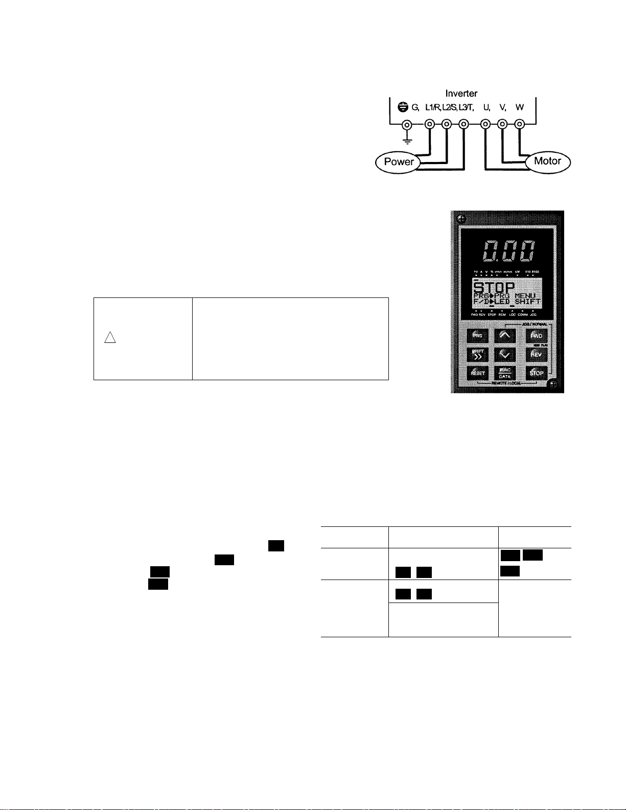
3. Operation
3-1 Inspection and Preparation before Operation
Check the following before operation:
① Check that the connection is correct.
In particular, check that the power supply is not connected
to any of the U, V, and W output terminals and that the
ground terminal is securely grounded.
② Check for short-circuits and ground faults between the
terminals and live sections.
③ Check for loose terminals, connectors, or screws.
④ Check that the motor is separated from mechanical
equipment.
⑤ Turn off switches before turning power to ensure that the
inverter will not start or operate abnormally at power-on.
⑥ Check the following after power-on:
a. Check that no alarm message is displayed on the keypad
panel (see Figure 3-1-2).
b. Check that the fan inside the inverter is rotating. (For
inverters with 2HP or more)
Be sure to put on the surface cover
before turning on the power (close).
Never remove the cover while the power
!
WARNING
is applied to the inverter.
To ensure safety, do not operate
switches with wet hands.
Electric shock may result
Fig. 3-1-1 Inverter connection
Fig. 3-1-2
Display on keypad panel at power-on
3-2 Operation Method
There are various methods of operation. Select a method of operation according to operating purpose and
specifications by referring to Section 4-2, "Operating the Keypad Panel," and Chapter 5, "Explanation of
Functions." Table 3-2-1 lists general operation methods
3-3 Trial Run
Upon confirming that inspection results are normal (see Section 3-1), proceed with a trial run. The initial
operation mode (set at factory) is using the keypad panel.
① Turn power on and confirm that frequency
display 0.00Hz is blinking on the LED monitor.
② Set the frequency to about 5Hz using key.
③ To start the run, press key (for forward
rotation) or key (for reverse rotation). To
stop, press key.
REV
STOP
FWD
∧
④ Check the following items :
a. Is the rotating direction correct?
b. Is the rotation smooth? (no buzzing or
abnormal vibration)
c. Is acceleration and deceleration smooth?
If no abnormality is detected, increase the frequency and check the above items again.
If the results of the trial run are normal, start a formal run.
Notes: - If an error is detected in the inverter or motor, immediately stop the operation and attempt to
determine the cause of error referring to Chapter 7, "Troubleshooting."
- As voltage is still applied to the main circuit terminals (L1/R, L2/S, L3/T) and auxiliary
control-power terminals (R0, T0) even when the output from the inverter is terminated, do not
touch the terminals. The smoothing capacitor in the inverter is being charged after the power is
turned off and it is not discharged immediately. Before touching an electric circuit, confirm that
the charge lamp is off or a multimeter is indicating a low voltage at the terminals.
Table 3-2-1 General operation methods
Operation
command
Operation
using keypad
panel
Operation
using
external
signal
terminals
Frequency setting
Keys on keypad panel
∧
∨
∧
∨
Freq. Setting POT (VR),
analog voltage,
analog current
FWD
STOP
Contact input
(switch)
Terminals
FWD-CM and
REV-CM
Operation
command
REV
3-1
Page 35

4. Keypad Panel
The keypad panel has various functions for specifying operations such as keypad operation (frequency setting,
run/stop command), confirming and changing function data, confirming status, and copying.
Review the use of each function before commencing running.
The keypad panel can also be removed or inserted during running. However, if the keypad panel is removed
during a keypad panel operation (e.g., run/stop, frequency setting), the inverter stops and outputs an alarm.
4-1 Appearance of Keypad Panel
LED monitor:
Four-digit 7-segment display
Used to display various items of monitored data such
as setting frequency, output frequency and alarm
code.
:
Control keys (valid during keypad panel
operation):
Used for inverter run and stop
FED
: Forward operation command
REV
: Reverse operation command
STOP
: Stop command
Operation keys
Used for screen switching, data change,
frequency setting, etc.
:
Auxiliary information indication for LED monitor
Selected units or multiple of the monitored data (on
the LED monitor) are displayed on the top line of the
LCD monitor. The symbol indicates selected
units or multiple number. The symbol ▲ indicates
there is an upper screen not currently displayed.
LCD monitor
:
Used to display such various items of information as
operation status and function data. An operation
guide message, which can be scrolled, is displayed
at the bottom of the LCD monitor.
This LCD monitor has a backlight feature which
turns on when the control power is applied or any
keypad key is pressed, and stays on approximately 5
minutes after the last key stroke.
Indication on LCD monitor
:
Displays one of the following operation status:
FWD: Forward operation REV: Reverse operation
STOP: Stop
Displays the selected operation mode:
REM: Terminal block LOC: Keypad panel
COMM: Communication terminal
JOG: Jogging mode
The symbol ▼ indicates there is a lower screen not
currently displayed.
RUN LED
:
Indicates that an operation command was input by
pressing the or key.
FWD
REV
Table 4-1-1 Functions of operation keys
Operation key Main function
PRG
FUNC
DATA
,
∨
SHIFT
>>
RESET
+
+
∧
RESET
∧
STOP
STOP
Used to switch the current screen to the menu screen or switch to the initial screen in
the operation/trip mode.
Used to switch the LED monitor or to determine the entered frequency, function code,
or data.
Used to change data, move the cursor up or down, or scroll the screen
Used to move the cursor horizontally at data change. When this key is pressed with
the up or down key, the cursor moves to the next function block.
Used to cancel current input data and switch the displayed screen. If an alarm occurs, this key
is used to reset the trip status (valid only when the alarm mode initial screen is displayed).
Used to switch normal operation mode to jogging operation mode or vice versa. The
selected mode is displayed on the LCD monitor.
Switches operation mode (from keypad panel operation mode to terminal block operation
mode or reverse). When these keys are operated, function F01 data is also switched from
0 to 1 or from 1 to 0. The selected mode is displayed on the LCD indicator.
4-1
Page 36

4-2 Keypad Panel Operation System (LCD screen, Level Structure)
A
4-2-1 Normal operation
The keypad panel operation system (screen transition, level structure) is structured as follows:
60.00
Operation mode
PRG
RESET RESET RESET
60.00
Program menu
FUNC
DATA
60.00
Screen for each
function
FUNC
DATA
FUNC
DATA
PRG
4-2-2 Alarm occurrence
If an alarm is activated, operation is changed from normal keypad panel operation to an alarm mode operation.
The alarm mode screen appears and alarm information is displayed.
The program menu, function screens, and supplementary screens remain unchanged as during normal
operation, though the switching method from program menu to alarm mode is limited to .
60.00
Operation mode
Alarm is
activated
Alarm
Alarm mode
larm reset processing (including )
PRG
Keypad panel operating system during normal operation
RESET
Alarm
Program menu
FUNC
DATA
RESET RESET
Alarm
Screen for each
function
FUNC
DATA
FUNC
DATA
60.00
Supplementary
screen
PRG
Alarm
Supplementary
screen
PRG
4-2
Page 37

Table 4-2-1 Overview of contents displayed for each level
No.
1
2
Level name Content
Operating
mode
Program
menu
This screen is for normal operation. Frequency setting by keypad panel and the
LED monitor switching are possible only when this screen is displayed.
Each function of the keypad panel is displayed in menu form and can be selected.
Selecting the desired function from the list and pressing displays the
screen of the selected function. The following functions are available as keypad
panel functions (menus).
No.
1
Menu
name
DATA SET
The code and name of the function are displayed.
Selecting a function displays a data setting screen for
checking, or modifying data.
DATA CHECK
2
The code and name of the function are displayed. Select
a function to display a screen for checking data. Modifying
data is possible as described above by going to the data
3
4
OPR MNTR
I/O CHECK
setting screen.
Can check various data on the operating status.
Can check the status of analog and digital input/output for
the inverter and options as an I/O checker.
MAINTENANC
5
Can check inverter status, life expectancy , communication
error status, and ROM version information as maintenance
6
LOAD FCTR
information.
Can measure maximum and average current and average
breaking force in load rate measurement.
ALM INF
7
Can check the operating status and input/output status at
the latest alarm occurrence.
ALM CAUSE
8
Can check the latest alarm or simultaneously occurred alarms
and alarm history. Selecting the alarm and pressing ,
displays the contents of alarm as troubleshooting.
DATA COPY
9
Places the function of one inverter in memory for copying
to another inverter.
3
Screen for
each function
4
Supplementary
screen
The function screen selected on the program menu appears, hence completing
the function.
Functions not completed (e.g., modifying function data, displaying alarm factors)
on individual function screens are displayed on the supplementary screen.
FUNC
DATA
Outline
FUNC
DATA
4-3
Page 38
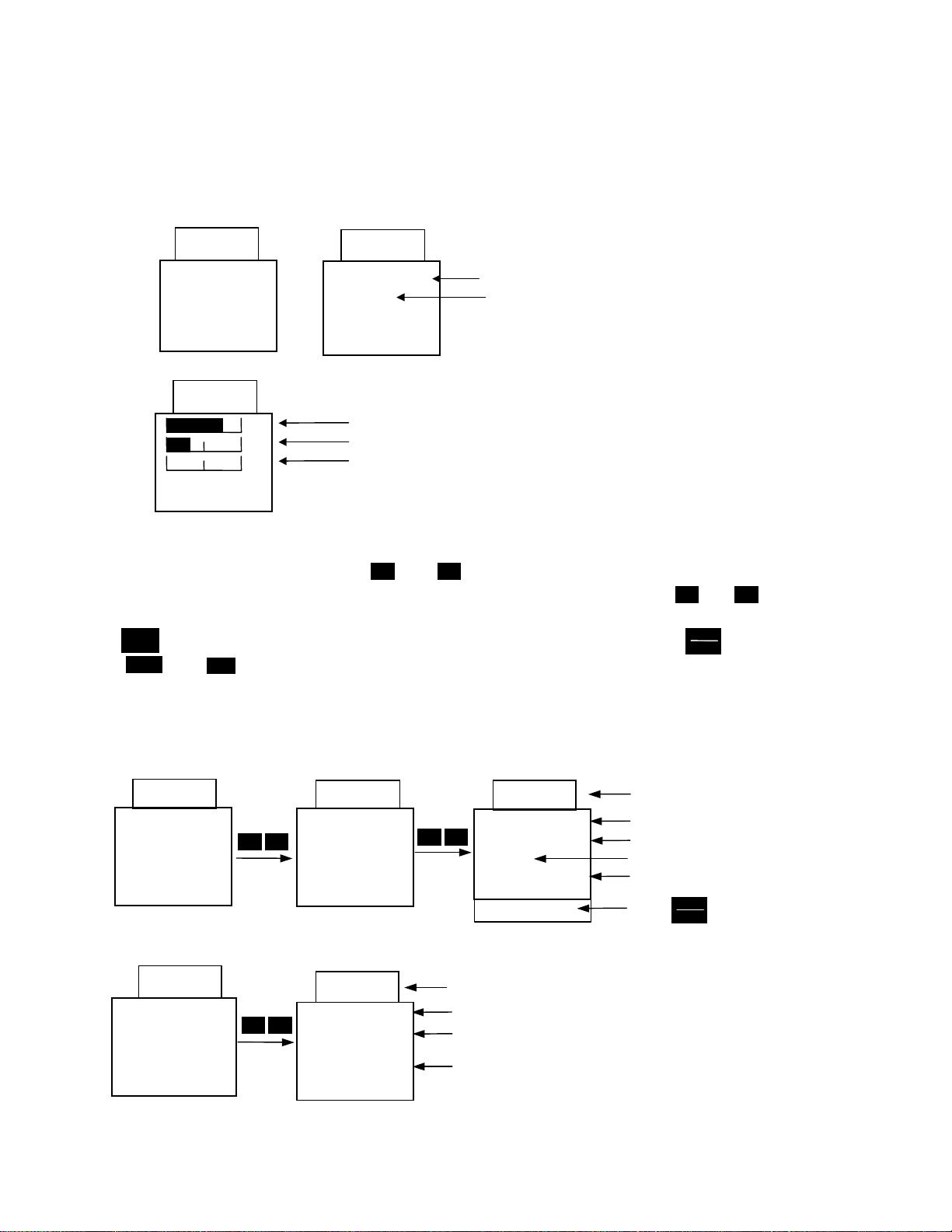
4-3 Operating Keypad Panel
p
4-3-1 Operation Mode
The screen for normal inverter operation includes a screen for displaying inverter operating status
and an operation guide and a screen for graphically displaying the operating status in the form of a
bar graph. Switching between both screens is possible using the E45 function.
1) Operation guide (E45=0)
2) Bar graph (E45=1)
60.00
STOP
PRG ⇒
MENU
⇒
F/D
60.00
Hz
A
%
Fout/Iout/TRQ
PRG
LED SHIFT
60.00
RUN
PRG ⇒
MENU
F/D
⇒
FWD
PRG
LED SHIFT
Output frequency (maximum frequency at full-scale)
Output current (200% of inverter rating at full-scale)
Torque calculation value (200% of motor rating at full-scale)
Rotating direction (no operation command, blank, yes: FWD/REV)
Operating status (no operation command, STOP, yes: RUN)
4-3-2 Setting digital frequency
On the operation mode screen, press or to display the set frequency on the LED. Data is
initially incremented and decremented in the smallest possible unit. Holding down or
increases or decreases the speed of increment or decrement. The digit to change data can be selected
using and then data can be set directly. To save the frequency settings, press .
Press and to return to the operation mode.
SHIFT
>>
RESET
PRG
If keypad panel settings are not selected, the present frequency setting mode appears on the LCD.
When selecting the PID function, PID command can be set with a process value. (Refer to technical
documentation for details).
1)
Digital (keypad panel) settings (F01=0 or C30=0)
60.00
RUN
PRG ⇒
MENU
F/D
⇒
LED SHIFT
PRG
∧ ∨
<DIG.SET Hz>
LOCAL
50
− 400
F/D
⇒
2) Other than digital setting
60.00
RUN
PRG⇒PRG MENU
F/D
⇒
LED SHIFT
∧ ∨
<REMOTE REF>
12+V1
F/D
⇒
∧ ∨
60.00
DATA SET
60.00
DATA SET
56.89
<DIG.SET Hz>
∧ ∨
LOCAL
50
−
400
F/D
⇒
DATA SET
STORING...
Frequency setting value
Screen ex
Present frequency setting mode
Operation guide
lanation
∧
FUNC
DATA
Frequency setting value
Screen explanation
Present frequency setting mode
Frequency setting range
Operations guide
FUNC
When pressed and writing data
DATA
∨
4-4
Page 39

4-3-3 Switching the LED monitor
On the normal operation, press to switch to LED monitor display.
When power is turned on, the monitor contents set by the function (E43) are displayed on the LED.
When stopping
E43
0 Setting frequency
1 Setting frequency
2 Setting frequency Setting frequency
3 Output current Output current A
4 Output voltage
5 Synchronous
6 Line speed setting
7 Load rotation
8 Torque calculation
9 Power
10 PID setting value PID setting value
11 PID remote setting
12 PID feedback
(E44 = 0) (E44 = 1)
(specified value)
speed setting
value
value
speed setting
value
value
consumption
value
value
FUNC
DATA
When running
(E44 =0,1)
Output frequency 1 (before slip compensation)
Output frequency 2 (after slip compensation)
Output voltage (specified value) V
Synchronous speed r/min.
Line speed m/min.
Load rotation speed r/min.
Torque calculation value %
Power consumption kW
PID remote setting value
PID feedback value
Unit Remarks
Hz
−
−
−
For 4 digits or more, the last
digits are cut, with x10, x100
marked on the indicator.
± indication
Displayed only when PID is
effective in PID operation
selection.
4-3-4 Menu screen
The “Program menu” screen is shown below. Only four items can be displayed simultaneously. Move the
∧
∨
cursor with or to select an item, then press to display the next screen.
1.DATA SETTING
2.DATA CHECK
3.OPR MNTR
4.I/O CHECK
⇒
5.MAINTENANC
6.LOAD FCTR
7.ALM INF
8.ALM CAUSE
9.DATA COPY
Display
4.I/O CHECK
⇒
5.MAINTENANC
6.LOAD FCTR
7.ALM INF
FUNC
DATA
4-3-5 Setting function data
On the “program menu” screen, select "1. Data Setting" then the “Function Select” screen appears
with function codes and names on it. Select the desired function.
60.00
RUN
PRG⇒PRG MENU
F/D
⇒
LED SHIFT
Function code Function name Data setting range
PRG
60.00
⇒
1.DATA SETTING
2.DATA CHECK
3.OPR MNTR
4.I/O CHECK
FUNC
DATA
60.00
F00DATA PRTC
F01FREQ COM 1
F02OPR METHOD
F03MAX Hz-1
FUNC
DATA
60.00
F01FREQ COM 1
0
0 − 11
Data
4-5
Page 40

The function code consists of alphanumeric characters. Unique alphabetical letters are assigned for each
function group.
Table 4-3-1
Function code Function Remarks
F00 - F42 Fundamental Functions
E01 - E47 Extension Terminal Functions
C01 - C33 Control Functions of Frequency
P01 - P09 Motor Parameters
H03 - H39 High Performance Functions
A01 - A18 Alternative Motor Parameters
U01 - U61 User Functions
o01 - o55 Optional Functions Can be selected only with an option connected
>>
To scroll “Function Select” screen rapidly , use + or + to move the screen in a unit grouped by
∧
>>
∨
alphabet.
F00DATA PRTC
F01FREQ CMD 1
F02OPR METHOD
F03MAX Hz-1
Select the desired function and press to switch to the “data setting” screen.
∨
>>
F00DATA PRTC
F01FREQ CMD 1
F02PPR METHOD
F03MAX Hz-1
FUNC
DATA
∨
+
F42TRQVECTOR1
E01X1 FUNC
E02X2 FUNC
E03X3 FUNC
>>
∧
+
A18SLIP COMP2
F00DATA P RT C
F01DATA PRTC
F02OPR METHOD
On the “data setting” screen, the data values on the LCD can be increased or decreased in the smallest
∧
possible unit by pressing or Holding down or expands the rate of change, thereby
enabling values to be modified more rapidly. Otherwise, select the digit to be modified using
∨
∨∧
>>
, then set data
directly. When data is modified, the value before modification will be displayed at the same time for
reference purpose. To save the data, press . Pressing cancels the changes made and
FUNC
DATA
RESET
returns to the “Function Select” screen. The modified data will be effective in inverter operation after the
data is saved by . The inverter operation does not change only if data is modified. When data
FUNC
DATA
setting is disabled in the case of “Data protected” or “Data setting invalid during inverter running,” make
necessary changes. Data cannot be modified for the following reasons :
Table 4-3-2
Display
LINK ACTIVE Currently writing from RS-485/link
NO SIGNAL(WE)
DATA PRTCTD
INV RUNNING
Reason for no modification Release method
Send a cancel command of function
option to Function is being made.
writing from RS-485. Stops a
“Write” operation from the link.
The edit enabling command function
is selected using a general-purpose
input terminal.
Data protection is selected for function
F00.
An attempt is made to change a
Among functions E01 to E09, turn the
terminal of data 19 (edit enabling
command selection) ON.
Change function F00 to 0.
Stop inverter operation.
function that cannot be changed
Turn FWD/REV command off.
FWD/REV ON
during inverter operation.
An attempt is made to change a
function that cannot be changed
with the FWD/REV command on.
4-6
Page 41
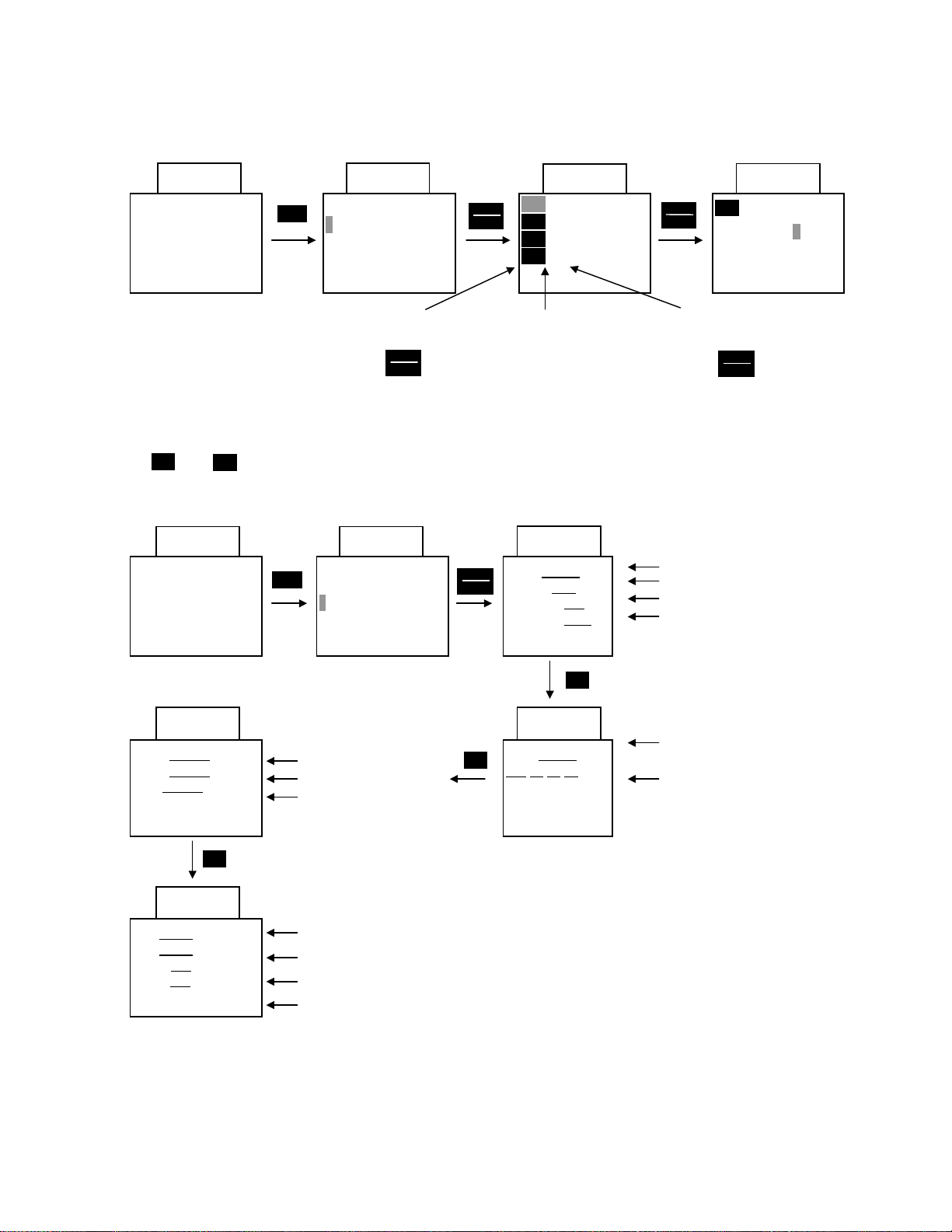
4-3-6 Checking function data
On the "Program menu" screen, select "2. DATA CHECK". The "Function Select" screen then appears with
function codes and names.
Select the desired function and press to check the function data. By pressing , the screen
60.00
RUN
PRG⇒PRG MENU
F/D
⇒
FWD
LED SHIFT
1.DATA SETTING
PRG
⇒
2.DATA CHECK
3.OPR MNTR
4.I/O CHECK
60.00
FUNC
DATA
Function code Data changed from initial value Data
FUNC
DATA
60.00
F00 0
F01 *1
F02 *1
F03 60Hz
FUNC
DATA
F00 DATA PRTC
0
0 - 1
FUNC
DATA
60.00
switches to the "Data setting" screen, to modify data.
4-3-7 Monitoring operating status
On the "Program menu" screen, select "3. OPR MNTR" to display the present operating status of inverter.
∧
Use and to switch between the four operation monitor screens.
RUN
PRG⇒PRG MENU
F/D
⇒
SYN=xxxxxx
LOD=xxxxxx
LIN=xxxxxx
SV=xxxxx
PV=xxxxx
TLD= xxx
TLB= xxx
∨
60.00 60.00
1.DATA SETTING
FWD
LED SHIFT
PRG
2.DATA CHECK
⇒
3.OPR MNTR
4.I/O CHECK
60.00
Synchronous rotation
∨
speed (r/min)
Load speed (r/min)
Line speed (m/min.)
60.00
%
%
PID setting value
PID feedback value
Driving torque limiting setting value
Braking torque limiting setting
FUNC
DATA
∨
60.00
Fout=xxxx.xHz
Iout= x.xx
Vout= xxx
TRQ= xxx
A
V
∨
60.00
Fref=xxxx.xHz
xxx
xx xx xx
%
Output frequency
Output current
Output voltage
Torque calculation method
Setting frequency
Operation status
FWD/REV: Rotating direction
IL: Current limiting
VL: Voltage limiting
LU: Under voltage
TL: Torque limiting
4-7
Page 42
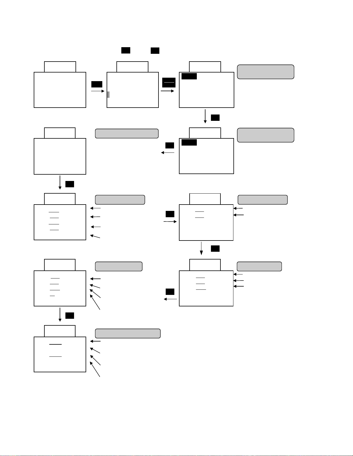
4-3-8 I/O check
On the “Program menu” screen, select "4. I/O Check" to display analog and digital input/output signal status
∧
for the inverter and options. Use ∧ and to switch between the eight screens of data.
60.00
RUN
PRG⇒PRG MENU
F/D
⇒
LED SHIFT
60.00
□Y1 □Y5
□Y2
□Y3
□Y4
∨
60.00
12=± xx.xV
22= xx.x
32=± xx.x
V2= xx.x
V
V
V
A0 =±xx.xV
CS= xx.x
DI = xxxx
D0= xx
mA
H
H
∨
60.00
P1=±xxxxx0p/s
Z1= 0p/s
P2=±xxxxx
Z2= 0p/s
0p/s
FWD
PRG
Output terminal status
:Signal OFF, :Signal ON
Analog input signal Analog input signal
Terminal 12 input voltage
Terminal 22 input voltage
(AIO option)
Terminal 32 input voltage
(AIO option)
Terminal V2 input voltage
option input status Output for meter
Terminal AO output voltage
(AIO option)
Terminal CS output current
(AIO option)
Digital input voltage
(HEX indication)
Digital output voltage
(HEX indication)
PG/SY option input status
Master-side A/B phase
frequency
Unused
Slave-side A/B phase
frequency
Unused
60.00 60.00
1.DATA SETTING
2.DATA CHECK
3.OPR MNTR
⇒
4.I/O CHECK
∨
Input terminal status
FUNC
DATA
■FWD □X3 □X7
□REV □X4 □X8
□X1 □X5 □X9
COMM
□X2 □X6
∨
□FWD □X3 □X7
□REV □X4 □X8
□X1 □X5 □X9
REV
□X2 □X6
∨
60.00
(terminals)
:Signal OFF, :Signal ON
Input terminal status
(via communication)
:Signal OFF, :Signal ON
60.00
C1= xx.xmA
∨
C2= xx.x
mA
∨
Terminal C1 input current
Terminal C2 input current
(AIO option)
60.00 60.00
FMA=xx.xV
∨
FMP=xx.x
FMP=xxxx
V
p/s
FMA output voltage
FMP output voltage
FMP output frequency
4-8
Page 43

4-3-9 Maintenance information
On the "Program menu" screen, select "5. Maintenance" to display information necessary for maintenance
and inspection. Use and to switch between the five screens of data.
60.00
RUN
FWD
PRG⇒PRG MENU
F/D
⇒
LED SHIFT
60.00
TCAP=xxxxxh
(61000h)
TFAN=xxxxx
(25000h)
NRK=xxxxx
NRR=xxxxx
NRO=xxxxx
h
∨
60.00
∧
∨
60.00
1.DATA SETTING
PRG
2.DATA CHECK
3.OPR MNTR
4.I/O CHECK
⇒
5.MAINTENANC
Capacitor on PC
board
accumulation time
( ):Judgment level.
Cooling fan operating
time
( ):Judgment level.
No. of communication
errors:keypad panel
No. of communication
errors:RS-485
No. of communication
errors:option
FUNC
DATA
∨
∨
60.00
TIME=xxxxxh
E D C= xxx
TMPI=xxxx
TMPF=xxxx
V
℃
℃
∨
60.00
Imax=x.xxA
CA P=xxx.x
%
60.00
INV=Hxxxx
KE YP AD =Kxxxxx
OP TI ON =Pxxxxx
Cumulative operating time
DC link circuit voltage
Maximum temperature inside inverter
(Maximum value in hour units)
Maximum temperature of heat sink
(Maximum value in hour units)
Maximum current(A)
(Maximum value in hour units)
Main capacitor capacity
ROM version: inverter
(40HP or more: H xxxxx
30HP or less:S xxxxx)
ROM version: keypad panel
ROM version: option
4-9
Page 44

4-3-10 Load rate measurement
On the "Program menu" screen, select "6. Load Rate Measurement". On the "Load rate measurement"
screen, the maximum current, average current, and average breaking power during the set measuring time
are measured and displayed.
60.00
FWD
RUN
PRG⇒PRG MENU
F/D
⇒
LED SHIFT
60.00
T=150s
Imax=0.00A
Iave=0.00A
BPave= 0.0%
T=3600s
Imax=56.4A
Iave=23.5A
BPave= 10.4%
60.00
60.00 60.00
1.DATA SETTING
PRG
2.DATA CHECK
3.OPR MNTR
4.I/O CHECK
5.MAINTENANC
⇒
6.LOAD FCTR
Displays the remaining
measuring time, when
reaches zero, ends the
measurement.
Display returns to initial values.
Maximum current
Average current
Average breaking power
(Motor rated output/100%)
Start measuring Set measuring time
FUNC
DATA
FUNC
DATA
T=360s
Imax=0.00A
Iave=0.00A
BPave= 0.0%
60.00
T=600s
Imax=0.00A
Iave= 0.00A
BPave= 0.0%
Measuring time
Change measuring using
and and .
>>
∨∧
4-10
Page 45

r
4-3-11 Alarm information
On the "Program menu" screen, select "7. Alarm Information". Various operating data when the latest alarm
∧
occurred is displayed. Use and to switch between the nine screens of alarm information data.
Up to four alarm codes can be displayed simultaneously.
60.00 60.00 OC1
RUN
FWD
PRG⇒PRG MENU
F/D
⇒
LED SHIFT
1.DATA SETTING
2.DATA CHECK
PRG
3.OPR MNTR
4.I/O CHECK
5.MAINTENANC
6.LOAD FCTR
⇒
7.ALM INF
OC1
TIME=xxxxxh
EDC= xxxV
TMPI=xxxx
℃
TMPF=xxxx℃
OC1
REM
□X2 □X6
□FWD □X3 □X7
□REV □X4 □X8
□X1 □X5 □X9
OC1
□Y1 □Y5
□Y2
□Y3
□Y4
Cumulative operating hours
at alarm occurrence
DC link circuit voltage
at alarm occurrence
Temperature inside inverter
at alarm occurrence
Heat sink temperature
at alarm occurrence
Input terminal status at alarm
occurrence (terminals)
□:Signal OFF, ■:Signal ON
Output terminal status
at alarm occurrence
□:Signal OFF, ■:Signal ON
Two times before previous
OC1
5=xxx
4=xxx
3=xxx
2=xxx
Multiple alarms
(Simultaneously occurring
alarms)
Alarm code
∨
FUNC
DATA
∨
∨
Previous alarm
Before previous alarm
Fout=xxxx.xHz
Iout= x.xx
Vout= xxxV
TRQ= xxx
OC1
Fref=xxxx.xHz
∨
xxx xx xx xx
∨
OC1
NRK=xxxxx
NRR=xxxxx
NRO=xxxxx
∨
□X2 □X6
OC1
COMM
□FWD □X3 □X7
□REV □X4 □X8
□X1 □X5 □X9
∨
OC1
0/1=xxx xxx
-1=xxx
xxx
-2=xxx
xxx
-3=xxx
xxx
∨
A
Code of latest alarm
(High speed blinking during alarm
alarm mode only)
Output frequency at alarm occurrence
Output current at alarm occurrence
Output voltage at alarm occurrence
%
∨
Torque calculation value at alarm
occurrence
Setting frequency at alarm
occurrence
Operating status at alarm
occurrence
FWD/REV:Rotating direction
IL :Current limiting
VL :Voltage limiting
LU :Under voltage
TL :Torque limiting
No. of communication errors
at alarm occurrence:keypad
panel
No. of communication errors
at alarm occurrence:RS-485
No. of communication errors
at alarm occurrence:Options
Input terminal status at alarm
occurrence (communication)
□:Signal OFF, ■:Signal ON
Latest alarm
No. of occurrences
Alarm history
No. of occurrences
Updated at alarm occurrence
If the cause of alarm is the
same as the same as the
previous one, only the numbe
of occurrences is incremented.
4-11
Page 46

4-3-12 Alarm history and factors
On the "Program menu" screen, select "8.Alarm Factors" to display the alarm history.
Press to display troubleshooting information for the alarm selected.
RUN
PRG⇒PRG MENU
F/D
xxxxxxxxxxxxx
xxxxxxxxxxxxx
xxxxxxxxxxxxx
xxxxxxxxxxxxx
FUNC
DATA
60.00
⇒
LED SHIFT
OC1
FWD
60.00
1.DATA SETTING
PRG
2.DATA CHECK
3.OPR MNTR
4.I/O CHECK
5.MAINTENANC
6.LOAD FCTR
7.ALM INF
⇒
8.ALM CAUSE
Alarm code of
the selected alarm
Alarm occurrence factors
of the selected alarm.
FUNC
DATA
FUNC
DATA
60.00
0/1=xxx xxx
-1=xxx
xxx
-2=xxx
xxx
-3=xxx
xxx
60.00
5=xxx
4=xxx
3=xxx
2=xxx
0/1=xxx xxx
-1=xxx
xxx
-2=xxx
xxx
-3=xxx
xxx
Latest alarm
Alarm history
Multiple alarms
(simultaneously occurring alarms)
Move the cursor using
∨
∧
and to select one
of the alarm occurred.
4-12
Page 47
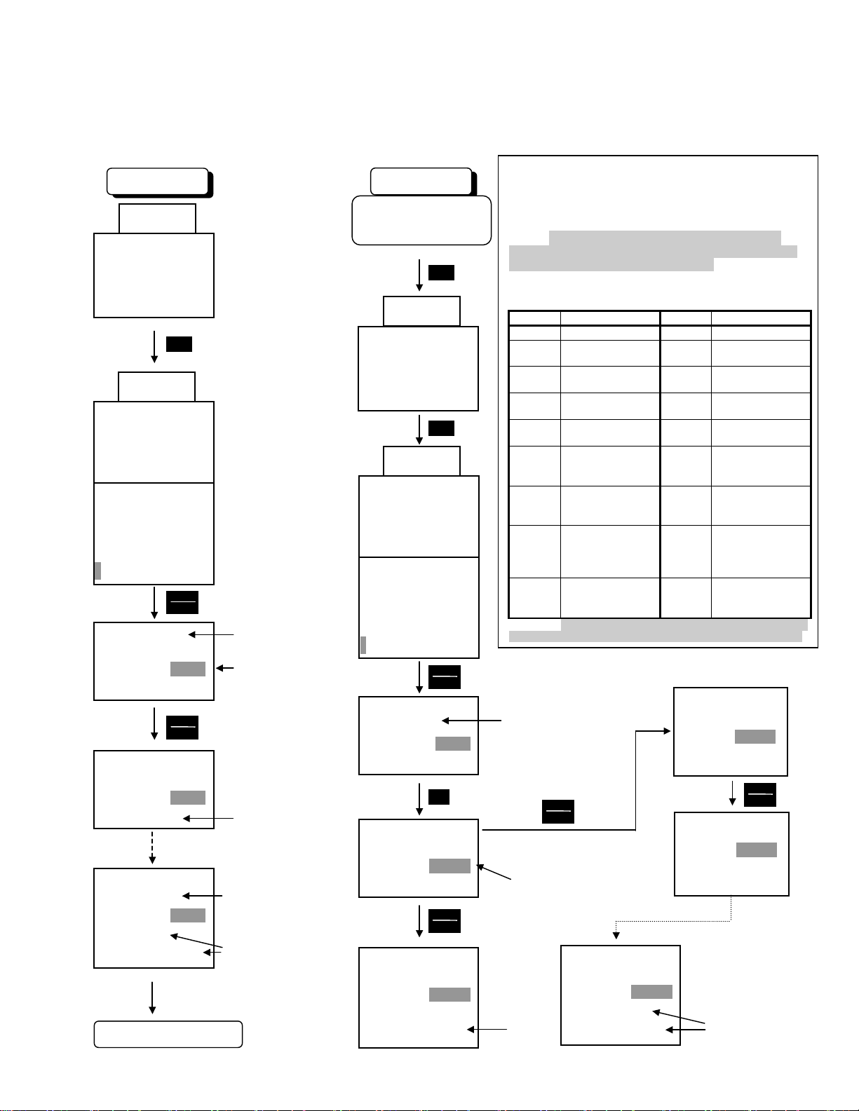
4-3-13 Data copy
On the "Program menu" screen, select "9. Data Copy" to display the data copy read screen. A copy
operation is then performed in the following order;reading inverter function data, removing the keypad panel,
attaching the keypad panel to another inverter, and writing the data to the inverter.
The "verify" feature also makes it possible to compare and check differences in the data stored in the keypad
panel and the data stored in the inverter.
60.00
RUN
PRG⇒PRG MENU
F/D
⇒
LED SHIFT
PRG
60.00
1.DATA SETTING
2.DATA CHECK
3.OPR MNTR
4.I/O CHECK
5.MAINTENANC
6.LOAD FCTR
7.ALM INF
8.ALM CAUSE
⇒
9.DATA COPY
<DATA COPY>
---- READ
<DATA COPY>
---- READ
QQQQ
<DATA COPY>
040HP-4
READ
COMPLETE
QQQQQQQQQQQQQQ
Remove keypad panel
FUNC
DATA
FUNC
DATA
DATA copy screen
Mode (read mode)
Reading
Data of inverter type
read by keypad panel
Read complete
Write data Read data
Attach keypad panel,
Turn power ON.
PRG
60.00
RUN
PRG⇒PRG MENU
F/D
⇒
LED SHIFT
PRG
60.00
1.DATA SETTING
2.DATA CHECK
3.OPR MNTR
4.I/O CHECK
5.MAINTENANC
6.LOAD FCTR
7.ALM INF
8.ALM CAUSE
⇒
9.DATA COPY
<DATA COPY>
040HP-4
READ
<DATA COPY>
040HP-4
WRITE
<DATA COPY>
040HP-4
WRITE
QQQQ
FUNC
DATA
∧
FUNC
DATA
When WRITE to the type of the inverter (capacity,
voltage and series) is same as the inverter type in
copy origin, all of the function will be written. When
the type of the inverter is different, the function
except the following will be written. However, in both
cases, F00(Data protection), P02/A11(Motor capacity),
P04/A13 (Motor tuning), H03(Data initializing), H31(RS-485
address) and o26/AIO optional adjustment will NOT be
written.
- The function which will NOT be copied when different inverter type
U codes cannot be copied in any case.
FUNC. NAME FUNC. NAME
F03 Max. freq. 1 F26 Motor sound
F04 Base freq. 1 E33
F05 Rated voltage 1 E34
F06 Max. voltage 1 E35
F09 Torque boost 1 E37
F10
F11
F12
F13 Electronic
In addition, when WRITE from inverter ROM No. is new one to old
one, WRITE except F01(Freq. command 1) without ERROR display.
Inverter type of data
stored by keypad panel
Electronic
thermal 1
(Select)
Electronic
thermal 1
(Level)
Electronic
thermal 1
(Thermal time
constant)
thermal
overload relay
H15
All of
"P"
code
All of
"A"
code
WRITE to the inverter with different
capacity, voltage and series.
<DATA COPY>
040HP-4
OL function
(Mode select)
OL function
OL function
OL2 function
Auto-restart
(Holding DC
Motor 1
Motor 2
WRITE
MEMORY ERROR
FUNC
FUNC
DATA
<DATA COPY>
040HP-4
DATA
WRITE
MEMORY ERROR
Mode (write mode)
QQQQ
<DATA COPY>
040HP-4
WRITE
COMPLETE
Writing
QQQQQQQQQQQQQQQQ
Write
complete
(Level)
(Timer)
(Level)
voltage)
4-13
Page 48

(
r
r
k
A
Data check
verify)
Error processing
60.00
RUN
PRG⇒PRG
MENU
F/D
⇒
LED SHIFT
PRG
60.00
1.DATA SETTING
2.DATA CHECK
3.OPR MNTR
4.I/O CHECK
5.MAINTENANC
6.LOAD FCTR
7.ALM INF
8.ALM CAUSE
⇒
9.DATA COPY
<DATA COPY>
040HP-4
READ
FUNC
DATA
Inverter type of data
stored in the keypad
panel
1) Change disabled during operation
If a write operation is attempted during an inverter
operation, or vice versa, the error message below will
appear.
After stopping the inverter and pressing , retry
RESET
the write operation.
<DATA COPY>
040HP-4
WRITE
INV RUNNING
2) Memory error
If a write operation is attempted while data has not
been saved (i.e., no data) in the keypad panel data
memory during the read mode, the following erro
message will appear:
<DATA COPY>
WRITE
MEMORY ERROR
∧
<DATA COPY>
040HP-4
WRITE
∧
<DATA COPY>
040HP-4
VERIFY
Mode (data check)
FUNC
DATA
<DATA COPY>
040HP-4
VERIFY
QQQQ
Data check in progress
<DATA COPY>
040HP-4
VERIFY
COMPLETE
QQQQQQQQQQQQQQQ
Data check complete
3) Verify error
During a data check (verify) operation, if data stored in
the keypad panel differs from data stored in the inverter,
the following error message is displayed to indicate the
function No. The data check is suspended.
To continue the data check and check for othe
mismatching data, press . To stop the data chec
and switch to another operation, press .
FUNC
DAT
RESET
<DATA COPY>
075HP-4
WRITE
ERR:F25
QQQQ
4) Data protection
When WRITE to the inverter which is protected by
"Data protection" function, the following error message
will appear. After released the protection, write
operation is attempted.
<DATA COPY>
040HP-4
WRITE
DATA PRTCTD
4-14
Page 49
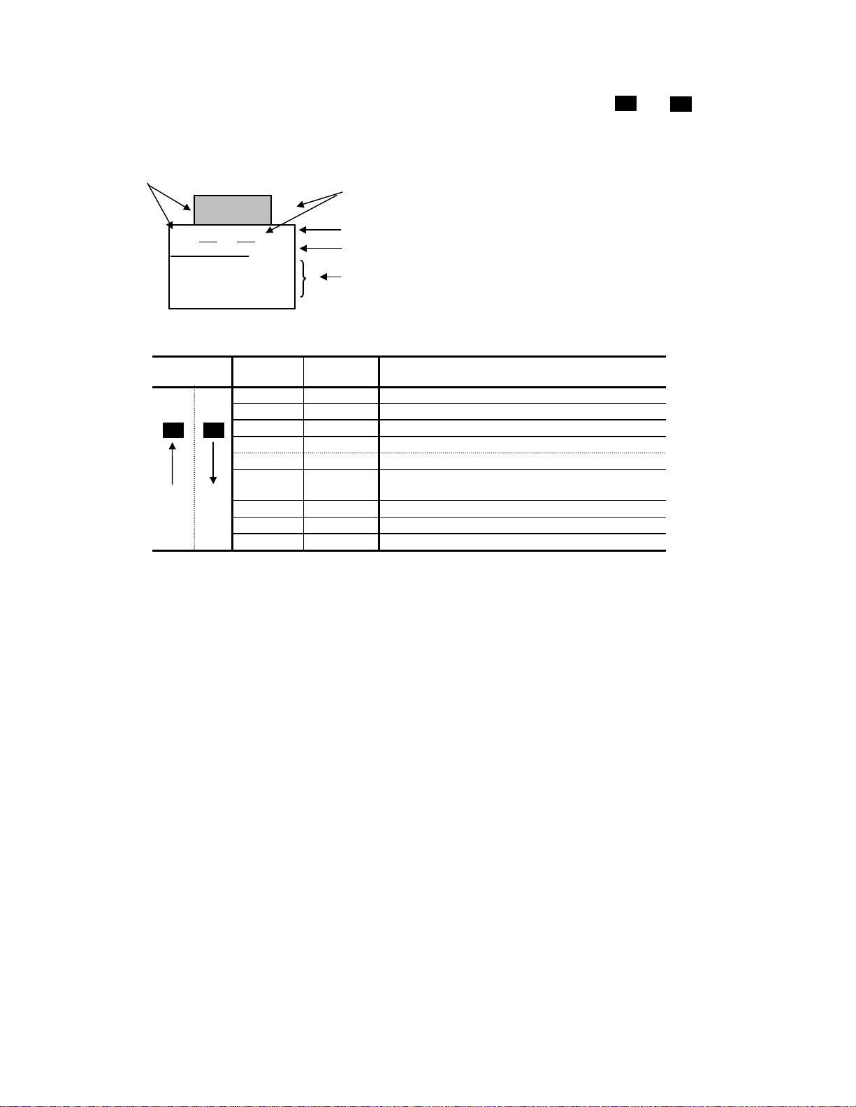
4-3-14 Alarm mode
∧
If an alarm occurs, the “Alarm screen” indicating the alarm contents is displayed. Use and to display alarm
history and multiple alarms (if more than two alarms occur simultaneously).
Alarm detection order
1.OC1
1=xxx xxx
xxxxxxxxxxxxx
PRG
⇒
PRG MENU
RESET
⇒
RESET
Alarm code
No. of consecutive occurrences
Alarm name
Operation guide
Alarm detection order
Operation
method
∨
∧
Alarm code: See Table 6-1-1
LED
display
LCD
display
Description
5. 5 No. 5 alarm
4. 4 No. 4 alarm
3. 3 No. 3 alarm
2. 2 No. 2 alarm
1. 1 No. 1 alarm (more than two alarms occurred)
Blank 0 Latest alarm (only one alarm occurred/alarm
released)
Blank -1 Previous alarm history
Blank -2 Alarm history before previous alarm
Blank -3 Alarm history two times before previous alarm
∨
4-15
Page 50

5. Function select
5-1 Function select list
F:Fundamental Functions
Func
No.
F00 Data protection F00 DA TA PRTC 0, 1 - - 0 NA
F01 Frequency command 1 F01 FRE Q CMD 1 0 to 11 - - 0 NA
F02 Operation method F02 OPR METHOD 0 to 4 - - 0 NA
F03 Maximum frequency 1 F03 MAX Hz-1 G11S: 50 to 400Hz Hz 1 60 NA
P11S: 50 to 120Hz
F04 Base frequency 1 F04 BASE Hz-1 G11S: 25 to 400Hz Hz 1 60 NA
P11S: 25 to 120Hz
F05 Rated voltage 1 F05 RATED V-1 0V: (Output voltage V 1 230:(230V class) NA
(at Base frequency 1) proportinal to sorce voltage) 460:(460V class)
80 to 240V: (230V class)
320 to 480V: (460V class)
F06 Maximum voltage 1 F06 MAX V-1 80 to 240V: (230V class) V 1 230:(230V class) NA
(at Maximum frequency 1) 320 to 480V: (460V class) 460:(460V class)
F07 Acceleration time 1 F07 ACC TIME1 0.01 to 3600s s 0.01 6.0 20.0 A
F08 Deceleration time 1 F08 DEC TIME1
F09 Torque boost 1 F09 TRQ BOOST1 0.0, 0.1 to 20.0 - 0.1 G11S:2.0 A
P11S:0.1
F10 Electronic (Select) F10 ELCTRN OL1 0, 1, 2 - - 1 A
F11 thermal 1 (Level) F11 OL LEVEL1 INV rated current 20 to 135% A 0.01 Motor rated current A
F12 (Therma l time constant) F12 TIME CNST1 0.5 to 75.0 min min 0.1 5.0 10.0 A
F13 Electronic thermal overload relay F13 DBR OL G11S [Up to 10[HP]] - -
(for braking resistor) 0, 1, 2 1 A
[15[HP] and above ]
0
P11S [Up to 15[HP]]
0, 2
[20[HP] and above ]
0
F14 Restart mode after F14 RESTART 0 to 5 - - 0 NA
momentary power failure
F15 Frequency limiter (High) F15 H LIMITER G11S: 0 to 400Hz Hz 1 70 A
F16 (Low) F16 L LIMITER P11S: 0 to 120Hz 0 A
F17 Gain (for freq. set signal) F17 FREQ GAIN 0.0 to 200.0% % 0.1 100.0 A
F18 Bias frequency F18 FREQ BIAS G11S: -400.0 to +400.0Hz Hz 0.1 0.0 A
P11S: -120.0 to +120.0Hz
F20 DC brake (Starting freq.) F20 DC BRK Hz 0 .0 to 60.0Hz Hz 0.1 0.0 A
F21 (Braking level) F21 DC BRK LVL G11S: 0 to 100% % 1 0 A
P 11S: 0 to 80%
F22 (Braking time) F22 DC BRK t 0.0s(Inactive) s 0.1 0.0 A
0.1 to 30.0s
F23 Starting frequency (Freq.) F23 START Hz 0.1 to 60.0Hz Hz 0.1 0.5 NA
F24 (Holding time) F24 HOLDING t 0.0 to 10.0s s 0.1 0.0 NA
F25 Stop frequency F25 STOP Hz 0.1 to 60.0Hz Hz 0.1 0.2 NA
F26 Motor sound (Carrier freq.) F26 MTR SOUND
F27 (Sound tone) F27 SOUND TONE 0 to 3 - - 0 A
F30 FMA (Voltage adjust) F30 FMA V-ADJ 0 to 200% % 1 100 A
F31 (Function) F31 FMA FUNC 0 to 10 - - 0 A
F33 FMP (Pulse rate) F33 FMP PULSES 300 to 6000p/s (full scale) p/s 1 1440 A
F34 (Voltage adjust) F34 FMP V-ADJ 0%, 1 to 200% % 1 0 A
F35 (Function) F35 FMP FUNC 0 to 10 - - 0 A
F36 30RY operation mode F36 30RY MODE 0, 1 - - 0 NA
F40 Torque limiter 1 (Driving) F40 DRV TRQ 1 G11S: 20 to 200%, 999 % 1 999 A
P11S: 20 to 150%, 999
F41 (Braking) F41 BRK TRQ 1 G11S: 0%, 20 to 200%, 999 999 A
P11S: 0%, 20 to 150%, 999
F42 Torque vector control 1 F42 TRQVECTOR1 0, 1 - - 0 NA
NAME LCD Display Setting range Unit
Nominal applied
motor
75HP or less 0.75 to 15kHz
G11
100HP or more 0.75 to 10kHz
30HP or less 0.75 to 15kHz
P11
40HP to 100HP 0.75 to 10kHz
125HP or more 0.75 to 6kHz
Setting range
Min.
Unit
kHz 1 2 A
Factory setting
-30HP 40HP-
0
0
0
Change
during op
User
Remark
Set value
5-1
Page 51

E:Extension Terminal Functions
Func
No.
E01 X1 terminal function E01 X1 FUNC 0 to 35 - - 0 NA
E02 X2 terminal function E02 X2 FUNC 1 NA
E03 X3 terminal function E03 X3 FUNC 2 NA
E04 X4 terminal function E04 X4 FUNC 3 NA
E05 X5 terminal function E05 X5 FUNC 4 NA
E06 X6 terminal function E06 X6 FUNC 5 NA
E07 X7 terminal function E07 X7 FUNC 6 NA
E08 X8 terminal function E08 X8 FUNC 7 NA
E09 X9 terminal function E09 X9 FUNC 8 NA
E10 Acceleration time 2 E10 ACC TIME2 s 0.01 6.00 20.00 A
E11 Deceleration time 2 E11 DEC TIME2 6.00 20.00 A
E12 Acceleration time 3 E12 ACC TIME3 6.00 20.00 A
E13 Deceleration time 3 E13 DEC TIME3 6.00 20.00 A
E14 Acceleration time 4 E14 ACC TIME4 6.00 20.00 A
E15 Deceleration time 4 E15 DEC TIME4
E16 Torque limiter 2 (Driving) E16 DRV TRQ 2 G11S: 20 to 200%, 999 % 1 999 A
P11S: 20 to 150%, 999
E17 (Braking) E17 BRK TRQ 2 G11S: 0%, 20 to 200%, 999 % 1 999 A
P11S: 0%, 20 to 150%, 999
E20 Y1 terminal function E20 Y1 FUNC 0 to 37 - - 0 NA
E21 Y2 terminal function E21 Y2 FUNC 1 NA
E22 Y3 terminal function E22 Y3 FUNC 2 NA
E23 Y4 terminal function E23 Y4 FUNC 7 NA
E24 Y5A, Y5C terminal func. E24 Y5 FUNC 10 NA
E25 Y5 RY operation mode E25 Y5RY MODE 0,1 - 1 0 NA
E30 FAR function (Hysteresis) E30 FAR HYSTR 0.0 to 10.0Hz Hz 0.1 2.5 A
E31 FDT function (Level) E31 FDT1 LEVEL G11S: 0 to 400Hz Hz 1 60 A
P11S: 0 to 120Hz
E32 signal (Hysteresis) E32 FDT1 HYSTR 0.0 to 30.0Hz Hz 0.1 1.0 A
E33 OL1 function(Mode select) E33 OL1 WARNING 0: Thermal calculation - - 0 A
1: Output current
E34 signal (Level) E34 OL1 LEVEL G11S: 5 to 200% A 0.01 Motor rated current A
P11S: 5 to 150%
E35 (Timer) E35 OL1 TIMER 0.0 to 60.0s s 0.1 10.0 A
E36 FDT2 function (Level) E36 FDT2 LEVEL G11S: 0 to 400Hz Hz 1 60 A
P11S: 0 to 120Hz
E37 OL2 function (Level) E37 OL2 LEVEL G11S: 5 to 200% A 0.01 Motor rated current A
P11S: 5 to 150%
E40 Display coefficient A E40 COEF A -999.00 to 999.00 - 0.01 0.01 A
E41 Display coefficient B E41 COEF B -999.00 to 999.00 - 0.01 0.00 A
E42 LED Display f ilter E42 DISPLAY FL 0.0 to 5.0s s 0.1 0.5 A
E43 LED Monitor (Function) E43 LED MNTR 0 to 12 - - 0 A
E44 (Display at STOP mode) E44 LED MNTR2 0, 1 - - 0 A
E45 LCD Monitor (Function) E45 LCD MNTR 0, 1 - - 0 A
E46 (Language) E46 LANGUAGE 0 to 5 - - 1 A
E47 (Contrast) E47 CONTRAST 0(soft) to 10(hard) - - 5 A
NAME LCD Displa y Setting range Unit
0.01 to 3600s
Min.
Unit
6.00 20.00 A
Factory setting
-30HP 40HP-
Change
during op
User
Set value
Remark
C:Control Functions of Frequency
Func
No.
C01 Jump frequency (Jump freq. 1) C01 JUMP Hz 1 Hz 1 0 A
C02 (Jump freq. 2) C02 JUMP Hz 2 0 A
C03 (Jump freq. 3) C03 JUMP Hz 3
C04 (Hysteresis) C04 JUMP HYSTR 0 to 30Hz Hz 1 3 A
C05 Multistep frequency (Freq. 1) C05 MULTI Hz-1 Hz 0.01 0.00 A
C06 setting (Freq. 2) C06 MULT I Hz-2 0.00 A
C07 (Freq. 3) C07 MUL TI Hz -3 0.00 A
C08 (Freq. 4) C08 MUL TI Hz -4 0.00 A
C09 (Freq. 5) C09 MUL TI Hz -5 0.00 A
C10 (Freq. 6) C10 MUL TI Hz -6 0.00 A
C11 (Freq. 7) C11 MUL TI Hz -7 0.00 A
C12 (Freq. 8) C12 MUL TI Hz -8 0.00 A
C13 (Freq. 9) C13 MUL TI Hz -9 0.00 A
C14 (Freq. 10) C14 MULTI Hz-10 0.00 A
C15 (Freq. 11) C15 MULTI Hz-11 0.00 A
C16 (Freq. 12) C16 MULTI Hz-12 0.00 A
C17 (Freq. 13) C17 MULTI Hz-13 0.00 A
C18 (Freq. 14) C18 MULTI Hz-14 0.00 A
C19 (Freq. 15) C19 MULTI Hz-15
NAME LCD Display Sett ing range Unit
G11S: 0 to 400Hz
P11S: 0 to 120Hz
G11S: 0.00 to 400.00Hz
P11S: 0.00 to 120.00Hz
Min.
Unit
0 A
0.00 A
Factory setting
-30HP 40HP-
Change
during op
User
Set value
5-2
Remark
Page 52

Func
No.
C20 JOG frequency C20 JOG Hz G11S:0.00 to 400.00Hz Hz 0.01 5.00 A
P11S:0.00 to 120.00Hz
C21 PATTERN(Mode select) C21 PATTERN 0,1,2 - - 0 NA
operation
C22 (Stage 1) C22 STAGE 1 Operation time:0.00 to 6000s s 0.01 0.00 F1 A
C23 (Stage 2) C23 STAGE 2 F1 to F4 and R1 to R4 0.00 F1 A
C24 (Stage 3) C24 STAGE 3 0.00 F1 A
C25 (Stage 4) C25 STAGE 4 0.00 F1 A
C26 (Stage 5) C26 STAGE 5 0.00 F1 A
C27 (Stage 6) C27 STAGE 6 0.00 F1 A
C28 (Stage 7) C28 STAGE 7 0.00 F1 A
C30 Frequency command 2 C30 FREQ CMD 2 0 to 11 - - 2 NA
C31 Bias(terminal[12]) C31 BIAS 12 -100.0 to +100.0% % 0.1 0.0 A
C32 Gain(terminal[12]) C32 GAIN 12 0.0 to +200.0% % 0.1 100.0 A
C33 Analog setting signal filter C33 REF FILTER 0.00 to 5.00s s 0.01 0.05 A
NAME LCD Display Setting range Unit
Min.
Factory setting
Unit
-30HP 40HP-
Change
during op
User
Set value
Remark
P:Motor Parameters
P01 Number of motor 1 poles P01 M1 POLES 2 to 14 - 2 4 NA
P02 Motor 1 (Capacity) P02 M1-CAP Up to 30[HP]: 0.01 to 60HP HP 0.01 Motor Capacity NA
40[HP]and above: 0.01 to 800HP
P03 (Rated current) P03 M1-Ir 0.00 to 2000A A 0.01 Motor rated current NA
P04 (Tuning) P04 M1 TUN1 0, 1, 2 - - 0 NA
P05 (On-line Tuning) P05 M1 TUN2 0, 1 - - 0 NA
P06 (No-load current) P06 M1-Io 0.00 to 2000A A 0.01 NA
P07 (%R1 setting) P07 M1-%R1 0.00 to 50.00% % 0.01 A
P08 (%X setting) P08 M1-%X 0.00 to 50.00% % 0.01 A
P09 Slip compensation control 1 P09 SLIP COMP1 0.00 to 15.00Hz Hz 0.01 0.00 A
Fuji STANDARD RATED
VALUE
Fuji STANDARD RATED
VALUE
Fuji STANDARD RATED
VALUE
H:High Performance Functions
H03 Data initializing H03 DATA INIT 0, 1 - - 0 NA
H04 Auto-reset (Times) H04 AUTO-RESET 0, 1 to 10 times - 1 0 A
H05 (Reset in terval) H05 RESET INT 2 to 20s s 1 5 A
H06 Fan stop operation H06 FAN STOP 0, 1 - - 0 A
H07 ACC/DEC pattern (Mode select) H07 ACC PTN 0,1,2,3 - - 0 NA
H08 Rev. phase sequence lock H08 REV LOCK 0, 1 - - 0 NA
H09 Start mode H09 START MODE 0, 1, 2 - - 0 NA
H10 Energy-saving operation H10 ENERGY SAV 0, 1 - - G11S:0 A
P11S:1
H11 DEC mode H11 DEC MODE 0, 1 - - 0 A
H12 Instantaneous OC limiting H12 INST CL 0, 1 - - 1 NA
H13 Auto-restart (Restart time) H13 RESTART t 0.1 to 10.0s s 0.1 0.1 0.5 NA
H14 (Freq. fall rate) H14 FALL RATE 0.00 to 100.00Hz/s Hz/s 0.01 10.00 A
H15 (Holding DC voltage) H15 HOLD V 3ph 230V class: 200 to 300V V 1 230V class:235V A
3ph 460V class: 400 to 600V 460V class:470V
H16 (OPR command selfhold time) H16 SELFHOLD t 0.0 to 30.0s, 999 s 0.1 999 NA
H18 Torque control H18 TRQ CTRL G11S:0, 1, 2, P 11S:0 (Fixed) - - 0 NA
H19 Active drive H19 AUT RED 0, 1 - - 0 A
H20 PID control (Mode select) H20 PID MODE 0, 1, 2 - - 0 NA
H21 (Feedback signal) H21 FB SIGNAL 0, 1, 2, 3 - - 1 NA
H22 (P-gain) H22 P-GAIN 0.01 to 10.00 times - 0.01 0.1 A
H23 (I-gain) H23 I-GAIN 0.0 , 0.1 to 3600s s 0.1 0.0 A
H24 (D-gain) H24 D-GAIN 0.00s , 0.01 to 10.0s s 0.01 0.00 A
H25 (Feedback filter) H25 FB FILTER 0.0 to 60.0s s 0.1 0.5 A
H26 PTC thermistor (Mode select) H26 PTC MODE 0, 1 0 A
H27 (Level) H27 PTC LEVEL 0.00 to 5.00V V 0.01 1.60 A
H28 Droop operation H28 DROOP G11S:-9.9 to 0.0Hz, P11S:0.0 (Fixed.) Hz 0.1 0 .0 A
H30 Serial link (Function select) H30 LINK FUNC 0, 1, 2, 3 - - 0 A
H31 Modbus-RTU (Address) H31 ADDRESS 0 (broadcast), 1 to 247 - 1 1 NA
H32 (Mode select on no response error) H32 MODE ON ER 0, 1, 2, 3 - - 0 A
H33 (Timer) H33 TIMER 0.0 to 60.0s s 0.1 2.0 A
H34 (Baud rate) H34 BAUD RATE 0, 1, 2, 3 - - 1 A
H35 (Data length) H35 LENGTH 0 (8-bit fixed) - - 0 A
H36 (Parity check) H36 PARITY 0, 1, 2 - - 0 A
H37 (Stop bits) H37 STOP BITS 0(2bit), 1(1bit) - - 0 A
H38 (No response error detection time) H38 NO RES t 0 (No detection), 1 to 60s s 1 0 A
H39 (Response interval) H39 INTERVAL 0.00 to 1.00s s 0.01 0.01 A
5-3
Page 53

A:Alternative Motor Parameters
Func
No.
A01 Maximum frequency 2 A01 MAX Hz-2 G11S: 50 to 400Hz Hz 1 60 NA
P11S: 50 to 120Hz
A02 Base frequency 2 A02 BASE Hz-2 G11S: 25 to 400Hz Hz 1 60 NA
P11S: 25 to 120Hz
A03 Rated voltage 2 A03 RATED V-2 0: V 1 230:(230V class) NA
(at Base frequency 2 ) 80 to 240V:(230V class) 460:(460V class)
320 to 480V:(46 0V class)
A04 Maximum voltage 2 A04 MAX V-2 80 to 240V:(230V class) V 1 230:(230V class) NA
(at Base frequency 2) 320 to 480V:(460V class) 460:(460V class)
A05 Torque boost2 A05 TRQ BOOST2 0.0, 0.1 to 20.0 - - G11S:2.0 A
P11S:0.1
A06 Electronic (Select) A06 ELCTRN OL2 0, 1, 2 - - 1 A
therma l
overload
relay fo r
motor 2
A07 (Level) A07 OL LEVEL2 INV rated current 20%to135% A 0.01 Motor rated current A
A08 (Thermal time constant) A08 TIME CNST2 0.5 to 75.0 min min 0.1 5.0 10.0 A
A09 Torque vector control 2 A09 TRQVECTOR2 0, 1 - - 0 NA
A10 Number of motor-2 poles A10 M2 POLES 2 to 14 poles ploes 2 4 NA
A11 Motor 2 (Capacity) A11 M2-CAP Up to 30HP:0.01 to 60HP HP 0.01 Motor capacity NA
40HP and above:0.01to800HP
A12 (Rated current) A12 M2-Ir 0.00 to 2000A A 0.01 Motor rated current NA
A13 (Tuning) A13 M2 TUN1 0, 1, 2 - - 0 NA
A14 (On-line Tuning) A14 M2 TUN2 0, 1 - - 0 NA
A15 (No-load current) A15 M2-Io 0.00 to 2000A A 0.01 Fuji standard rated value NA
A16 (%R1 setting) A16 M2-%R1 0.00 to 50.00% % 0.01 Fuji standard rated value A
A17 (%X setting) A17 M2-%X 0.00 to 50.00% % 0.01 Fuji standard rated value A
A18 (Slip compensation control 2) A18 SLIP COMP2 0.00 to 15.00Hz Hz 0.01 0.00 A
NAME LCD Displa y Setting range Unit
Min.
Unit
Factory setting
-30HP 40HP-
Change
during op
User
Set value
Remark
U:User Functions
U01 Maximum compensation frequency U01 USER 01 75 A
during braking torque limit
U02 1st S-shape level at acceleration U02 USER 02 1 to 50% % 1 10 NA
U03 2nd S-shape level at acceleration U03 USER 03 1 to 50% % 1 10 NA
U04 1st S-shape level at deceleration U04 USER 04 1 to 50% % 1 10 NA
U05 2nd S-shape level at deceleration U05 USER 05 1 to 50% % 1 10 NA
U08 Main DC link capacitor (Initial value) U08 USER 08 0 to 65535 - 1 xxxx A
U09 (Measured value) U09 USE R 09 0 to 65535 - 1 0 A
U10 PC board capacitor powered on time U10 USER 10 0 to 65 535h h 1 0 A
U11 Cooling fan operating time U11 USER 11 0 to 65535h h 1 0 A
U13 Magnetize current vibration damping gain U13 USE R 13 0 to 32767 - 1 819 410 A
U15 Slip compensation filter time constant U15 USER 15 0 to 32 767 - 1 556 546 A
U23 Integral gain of continuous operation U23 USER 23 1738 1000 A
at power failure
U24 Proportional gain of continuous U24 USER 24 1024 1000 A
operation at power failure
U48 Input phase loss protection U48 USER 48 -75HP 100HP- NA
U49 RS-485 protocol selection U49 USER 49 0, 1 - - 1 NA
U56 Speed agreement (Detection width) U56 USER 56 0 to 50% % 1 10 A
U57 /PG error (Detection timer) U57 USER 57 0.0 to 10.0s s 0.1 0.5
U58 PG error selection U58 USER 58 0, 1 - - 1 NA
U59 Braking-resistor function select(up to 30HP) U59 USER 59 00 NA
Manufacturer's function(40HP or more)
U60 Regeneration avoidance at deceleration U60 USER 60 0 NA
U61 Voltage detect offset and gain adjustment U61 USER 61 --30HP:0(Fixed.) 0 A
40HP--:0, 1, 2
U89 Motor overload memory U89 USER 89 0.1 - - 1 A
retention
0 to 65535
0 to 65535
0 to 65535
0, 1, 2
00 to A8(HEX)
0, 1
- 1
- 1
- 1
- -
- 1
- -
- -
0 1
5-4
Page 54

Table 5-1-1 The factory setting value (details)
F11:Electric
thermal1(Level)
E34:OL1
Inverter type
FRNF25G11S-2UX 1.40 1/4 1.40 1.12 11.02 13.84
FRNF50G11S-2UX 2.00 1/2 2.00 1.22 6.15 8.80
FRN001G11S-2UX 3.00 1.00 3.00 1.54 3.96 8.86
FRN002G11S-2UX 5.80 2.00 5.80 2.80 4.29 7.74
FRN003G11S-2UX 7.90 3.00 7.90 3.57 3.15 20.81
FRN005G11S-2UX 12.6 5.00 12.6 4.78 3.34 23.57
FRN007G11S-2UX 18.6 7.50 18.6 6.23 2.65 28.91
FRN010G11S-2UX 25.3 10.00 25.3 8.75 2.43 30.78
FRN015G11S-2UX 37.3 15.00 37.3 12.7 2.07 29.13
FRN020G11S-2UX 49.1 20.00 49.1 9.20 2.09 29.53
FRN025G11S-2UX 60.0 25.00 60.0 16.7 1.75 31.49
230V G11S
FRN030G11S-2UX 72.4 30.00 72.4 19.8 1.90 32.55
FRN040G11S-2UX 91.0 40.00 91.0 13.6 1.82 25.32
FRN050G11S-2UX 115.0 50.00 115.0 18.7 1.92 24.87
FRN060G11S-2UX 137.0 60.00 137.0 20.8 1.29 26.99
FRN075G11S-2UX 174.0 75.00 174.0 28.6 1.37 27.09
FRN100G11S-2UX 226.0 100.00 226.0 37.4 1.08 23.80
FRN125G11S-2UX 268.0 125.00 268.0 29.8 1.05 22.90
FRN007P11S-2UX 18.6 7.50 18.6 6.23 2.65 28.91
FRN010P11S-2UX 25.3 10.00 25.3 8.75 2.43 30.78
FRN015P11S-2UX 37.3 15.00 37.3 12.7 2.07 29.13
FRN020P11S-2UX 49.1 20.00 49.1 9.20 2.09 29.53
FRN025P11S-2UX 60.0 25.00 60.0 16.7 1.75 31.49
FRN030P11S-2UX 72.4 30.00 72.4 19.8 1.90 32.55
FRN040P11S-2UX 91.0 40.00 91.0 13.6 1.82 25.32
FRN050P11S-2UX 115.0 50.00 115.0 18.7 1.92 24.87
230V P11S
FRN060P11S-2UX 137.0 60.00 137.0 20.8 1.29 26.99
FRN075P11S-2UX 174.0 75.00 174.0 28.6 1.37 27.09
FRN100P11S-2UX 226.0 100.00 226.0 37.4 1.08 23.80
FRN125P11S-2UX 268.0 125.00 268.0 29.8 1.05 22.90
FRN150P11S-2UX 337.0 150.00 337.0 90.4 0.96 21.61
function(Level)
E37:OL2
function(Level)
A07:Electric thermal
overload relay
for motor2
(Level)
[A] [HP] [A] [A] [%] [%]
Function code
*2 *1 *2 *1 *2 *1 *1
P02:Motor1
(Capacity)
A11:Motor2
(Capacity)
P03:Motor1
(Rated current)
A12:Motor2
(Rated current)
P06:Motor1
(No-load current)
A15:Motor2
(No-load current)
P07:Motor1
(%R1 setting)
A16:Motor2
(%R1 setting)
P08:Motor1
(%X setting)
A17:Motor2
(%X setting)
5-5
Page 55

Function code
*2 *1 *2 *1 *2 *1 *1
F11:Electric
thermal1(Level)
Inverter type
E34:OL1
function(Level)
E37:OL2
function(Level)
A07:Electric thermal
overload relay
for motor2
(Level)
[A] [HP] [A] [A] [%] [%]
FRNF50G11S-4UX 1.00 1/2 1.00 0.61 6.15 8.80
FRN001G11S-4UX 1.50 1.00 1.50 0.77 3.96 8.86
FRN002G11S-4UX 2.90 2.00 2.90 1.40 4.29 7.74
FRN003G11S-4UX 4.00 3.00 4.00 1.79 3.15 20.81
FRN005G11S-4UX 6.30 5.00 6.30 2.39 3.34 23.57
FRN007G11S-4UX 9.30 7.50 9.30 3.12 2.65 28.91
FRN010G11S-4UX 12.7 10.00 12.7 4.37 2.43 30.78
FRN015G11S-4UX 18.7 15.00 18.7 6.36 2.07 29.13
FRN020G11S-4UX 24.6 20.00 24.6 4.60 2.09 29.53
FRN025G11S-4UX 30.0 25.00 30.0 8.33 1.75 31.49
FRN030G11S-4UX 36.2 30.00 36.2 9.88 1.90 32.55
FRN040G11S-4UX 45.5 40.00 45.5 6.80 1.82 25.32
FRN050G11S-4UX 57.5 50.00 57.5 9.33 1.92 24.87
FRN060G11S-4UX 68.7 60.00 68.7 10.40 1.29 26.99
FRN075G11S-4UX 86.9 75.00 86.9 14.30 1.37 27.09
460V G11S
FRN100G11S-4UX 113.0 100.00 113.0 18.70 1.08 23.80
FRN125G11S-4UX 134.0 125.00 134.0 14.90 1.05 22.90
FRN150G11S-4UX 169.0 150.00 169.0 45.20 0.96 21.61
FRN200G11S-4UX 231.0 200.00 231.0 81.80 0.72 20.84
FRN250G11S-4UX 272.0 250.00 272.0 41.10 0.71 18.72
FRN300G11S-4UX 323.0 300.00 323.0 45.10 0.53 18.44
FRN350G11S-4UX 375.0 350.00 375.0 68.30 0.99 19.24
FRN400G11S-4UX 429.0 400.00 429.0 80.70 1.11 18.92
FRN450G11S-4UX 481.0 450.00 481.0 85.50 0.95 19.01
FRN500G11S-4UX 534.0 500.00 534.0 99.20 1.05 18.39
FRN600G11S-4UX 638.0 600.00 638.0 140.00 0.85 18.38
FRN007P11S-4UX 9.30 7.50 9.30 3.12 2.65 28.91
FRN010P11S-4UX 12.7 10.00 12.7 4.37 2.43 30.78
FRN015P11S-4UX 18.7 15.00 18.7 6.36 2.07 29.13
FRN020P11S-4UX 24.6 20.00 24.6 4.60 2.09 29.53
FRN025P11S-4UX 30.0 25.00 30.0 8.33 1.75 31.49
FRN030P11S-4UX 36.2 30.00 36.2 9.88 1.90 32.55
FRN040P11S-4UX 45.5 40.00 45.5 6.80 1.82 25.32
FRN050P11S-4UX 57.5 50.00 57.5 9.33 1.92 24.87
FRN060P11S-4UX 68.7 60.00 68.7 10.40 1.29 26.99
FRN075P11S-4UX 86.9 75.00 86.9 14.30 1.37 27.09
FRN100P11S-4UX 113.0 100.00 113.0 18.70 1.08 23.80
FRN125P11S-4UX 134.0 125.00 134.0 14.90 1.05 22.90
FRN150P11S-4UX 169.0 150.00 169.0 45.20 0.96 21.61
460V P11S
FRN200P11S-4UX 231.0 200.00 231.0 81.80 0.72 20.84
FRN250P11S-4UX 272.0 250.00 272.0 41.10 0.71 18.72
FRN300P11S-4UX 323.0 300.00 323.0 45.10 0.53 18.44
FRN350P11S-4UX 375.0 350.00 375.0 68.30 0.99 19.24
FRN400P11S-4UX 429.0 400.00 429.0 80.70 1.11 18.92
FRN450P11S-4UX 481.0 450.00 481.0 85.50 0.95 19.01
FRN500P11S-4UX 534.0 500.00 534.0 99.20 1.05 18.39
FRN600P11S-4UX 638.0 600.00 638.0 140.00 0.85 18.38
FRN700P11S-4UX 756.0 700.00 756.0 164.00 1.02 21.92
FRN800P11S-4UX 870.0 800.00 870.0 209.00 1.17 21.69
note 1) The factory setting described on *1 is the value of Fuji standard induction motor 460V/50Hz/4-poles.
The factory setting described on *1 is NOT changed automatically even function code P01/A10 (motor poles) is
changed to excluding 4-poles.
note 2) The minimum units of the data *2 is as follows.
Current value
[A]
Minimum units
[A]
0.00 to 9.99 0.01
10.0 to 99.9 0.1
100 to 999 1
1000 to 9990 10
P02:Motor1
(Capacity)
A11:Motor2
(Capacity)
P03:Motor1
(Rated current)
A12:Motor2
(Rated current)
P06:Motor1
(No-load current)
A15:Motor2
(No-load current)
P07:Motor1
A16:Motor2
(%R1 setting)
(%R1 setting)
P08:Motor1
(%X setting)
A17:Motor2
(%X setting)
5-6
Page 56

5-2 Function Explanation
A
A
F00 Data protection
F:
Fundamental function
XSetting can be made so that a set value cannot be
changed by keypad panel operation.
F 0 0 D A T A P R T C
Setting range 0 : The data can be changed.
1 : The data cannot be changed.
[Setting procedure ]
0 to 1: Press the and keys simultaneously
STOP
∧
to change the value from 0 to 1, then press the
to validate the change.
1 to 0: Press the and keys simultaneously
FUNC
DATA
STOP
∨
to change the value from 1 to 0, then press the
key to validate the change.
FUNC
DATA
F01 Frequency command 1
XThis function selects the frequency
setting method.
F 0 1 F R E Q C M D 1
0 : Setting by keypad panel operation ( key)
1 : Setting by voltage input (terminal [12 ](0 to +10V)
+ terminal [V2](0 to +10V) )
2: Setting by current input (terminal [C1] (4 to 20mA)).
3: Setting by voltage input + current input (terminal [12]
+ terminal [C1] ) (-10 to +10V + 4 to 20mA).
4: Reversible operation with polarity ( terminal [12]
(-10 to +10V))
5: Reversible operation with polarity ( terminal [12]
+[V1](Option) (-10 to +10V))
6: Inverse mode operation
(terminal [12] +[V2] (+10V to 0 ))
7: Inverse mode operation
(terminal [C1] (20 to 4mA))
8: Setting by UP/DOWN control mode 1
(initial value = 0) (terminals [UP] and [DOWN])
9: Setting by UP/DOWN control mode 2
(initial value =last final value)
(terminals [UP] and [DOWN])
See the function explanation of E01 to E09 for details.
10: Setting by pattern operation
See the function explanation C21 to C28 for details.
11: Setting by digital input or pulse train
* Optional. For details, see the instruction manual on options.
Related functions
E01 to E09
(Set values 19)
Related functions
E01 to E09
(Set values 17,18)
C30
∧ ∨
Related functions:
E01 to E09
(Set value 21)
Related functions:
E01 to E09
(Set value 17,18)
Related functions:
C21to C28
Maximum frequency
Set value:1,3
-10 0 +10 [V]
- Maximum frequency
Maximum frequency
F02 Operation method
Forward / Inverse operation
Frequency setting value
nalog input terminal
[12] , [V2]
Set value:4,5
Frequency setting value
0
0 4 20 [mA]
nalog input terminal
[C1]
Forward operation
(set value: 1, 3, 4, 5)
Inverse operation
(set value::6)
Related functions:
E01 to E09
(Set value 21)
Forward operation
(set value: 2)
Inverse operation
(set value: 7)
XThis function sets the operation command input method.
F 0 2 OPR M E T H OD
Setting range 0: Key pad operation
( keys).
* - This function can only be changed when terminals FWD
and REV are open.
- REMOTE/LOCAL switching from the keypad panel
automatically changes the set value of this function.
- REMOTE/LOCAL can be changed by pressing the
key and key simultaneously.
RESET
FWD REV STOP
Press the for forward operation.
Press the for reverse operation.
Press the for deceleration to a stop.
FWD
REV
STOP
Input from terminals [FWD] and [REV] is
ignored.
(LOCAL)
1: Terminal operation( key active)
2: Terminal operation( key inactive)
3: Terminal operation( key active)
STOP
STOP
STOP
with Fuji start software.
4: Terminal operation( key inactive)
with Fuji start software.
STOP
STOP
5-7
Page 57

START SOFTWARE SELECTION DURING TERMINAL OPERATION
Active : Setting 3 or 4Inactive : Setting 1 or 2
POWER ON
RESET
NETWORK
MODE
POWER
FWD
OUTPUT
ALARM
RESET
FWD
OUTPUT
ALARM
NETWORK (LE-
CM)
FWD
(TERMINAL)
FWD
(NETWORK)
OUTPUT
POWER
FWD
OUTPUT
ALARM
RESET
FWD
OUTPUT
ALARM
NETWORK (LE-
CM)
FWD
. (TERMIAL)
FWD
(NETWORK)
OUTPUT
ER6
ER6
ALARM ALARM
ER6
RESET
NOTE) Safety software does not work at AUTO RESET mode and PRGRAMMING mode.
STOP KEY MODE SELCTION DURING TURMINAL OPERATION
Active : Seeting 1 or 3Inactive : Setting 2 or 4
STOP KEY
(Terminal mode)
STOP KEY
(Network mode)
FWD
STOP
OUTPUT
ALARM
NETWORK (LE-
CM)
FWD
(NETWORK)
STOP
.
OUTPUT
FWD
STOP
OUTPUT
ALARM
NETWORK (LE-
CM)
FWD
. (NETWORK)
STOP
OUTPUT
ER6
ER6
ALARM ALARM
5-8
ER6
Page 58
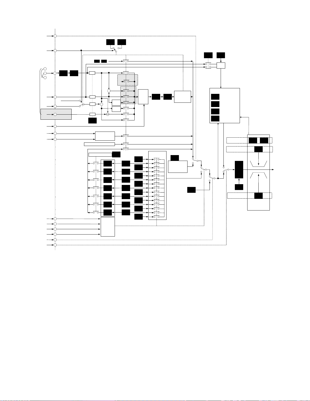
r
[
Hz2/Hz1] o
Frequency setting signals
[
Hz1/Hz2
[12
[C1
[V2
[V1
Option
[IVS]
[UP
[DOWN
[SS1
[SS2
[SS4
[SS8
[JOG
[Hz2/PID
[LE]
]
]
]
]
]
]
]
]
]
]
]
]
]
Gain Bias
C31 C32
C30 is selected
0
and C30=#1, #6
Frequency setting
Frequency setting by keypad panel
C33
D/I or pulse train (opt ional)
Pattern operation control
∧ ∨
+
+
+
+
Analog input filter
UP/DOWN control
C22
C23
C24
C25
C26
C27
C28
Switching
command
C30 F01
Feedback
selection
#0
#4
#2, #3,
C30
#7
0
+
+
Inverse
Inverse
C21
#3
F01
#2
#7
#6
#5
#1
#8,#9
#11
#10
Forward/
Reverse
operation
C12
C05
C13
C06
C14
C07
Bias frequency
Gain
Multistep frequency
switching
F18F17
Set frequency value
Negative polari ty
prevention
#1,#2,#3,#6,#7
H30
by Link function
Multistep frequencies 1 to 15
C15
C08
C16
JOG frequency
C20
H21
C09
H20
H22
H23
H24
H25
Feedback filter
PID control
Operation selection
Proportional
Integral
Differential
Maximum frequency
Upper-limit freque ncy
Lower-limit fr equency
Jump frequency
C01
C02
C03
C04
Limit signal
Limiter processi ng
F15
F16
A01F03
Set
frequency
value
C17
C10
C11
C18
C19
note) The numbers marked "#" means the setting value of each functions.
Frequency setting block diagram
5-9
Page 59

F03 Maximum frequency 1
XThis function sets the maximum output frequency for
motor 1.
XThis is a function for motor 1.
F 0 3 M A X H z - 1
Setting range G11S: 50 to 400 Hz
P11S: 50 to 120Hz
Setting a value higher than the rated value of the device
to be driven may damage the motor or machine.
Match the rating of the device.
F04
Base frequency 1
XThis function sets the maximum output frequency in the
constant-torque range of motor 1 or the output frequency
at the rated output voltage. Match the rating of the motor.
XThis is a function for motor 1.
F 0 4 B A S E H z - 1
Setting range G11S: 25 to 400Hz
P11S: 25 to 120Hz
Note: When the set value of base frequency 1 is higher
than that of maximum output frequency 1, the output
voltage does not increase to the rated voltage because
the maximum frequency limits the output frequency.
Output voltage
F06 Maximum
output voltage 1
F05 Rated voltage 1
Constant-torque range
F07 Acceleration time 1
F08 Deceleration time 1
XThis function sets the acceleration time for the output
frequency from startup to maximum frequency and the
deceleration time from maximum frequency to operation
stop.
F 0 7 ACC T I M E 1
F 0 8 DEC T I M E 1
Setting range Acceleration time 1: 0.01 to 3,600 seconds
Deceleration time 1: 0.01 to 3,600 seconds
Acceleration and deceleration times are represented by
the three most significant digits, thereby the setting of
three high-order digits can be set.
Set acceleration and deceleration times with respect to
maximum frequency. The relationship between the set
frequency value and acceleration/deceleration times is
as follows:
Set frequency = maximum frequency
The actual operation time matches the set value.
STOPFWD
Maximum frequency
Output freque ncy
Set frequen cy
Time
Output frequency
0
F05 Rated voltage 1
F04 Base
frequency 1
F03 Maximum
output frequency
XThis function sets the rated value of the voltage output
to motor 1. Note that a voltage greater than the supply
(input) voltage cannot be output.
XThis is a function for motor 1.
F 0 5 R A T E D V - 1
Setting range 230 V series: 0, 80 to 240V
460 V series: 0, 320 to 480V
Value 0 terminates operation of the voltage regulation
function, thereby resulting in the output of a voltage
proportional to the supply voltage.
Note: When the set value of rated voltage 1 exceeds
maximum output voltage 1, the output voltage does not
increase to the rated voltage because the maximum
output voltage limits the output voltage.
F06
Maximum voltage 1
XThis function sets the maximum value of the voltage
output for motor 1. Note that a voltage higher than the
supply (input) voltage cannot be output.
XThis is a function for motor 1.
F 0 6 M A X V - 1
Setting range 230 V series: 80 to 240V
460 V series: 320 to 480V
Note: When the set value of rated voltage 1 (F05) to "0",
this function is invalid.
Acceleration time
Deceleration time
Set frequency < maximum frequency
The actual operation time differs from the set value.
Acceleration(deceleration) operation time = set value x
(set frequency/maximum frequency)
Acceleration
operation time
Output frequency
Acceleration time
FWD
Maximum frequency
Deceleration
operation time
STOP
Set frequency
Time
Deceleration tim e
Note: If the set acceleration and deceleration times are
too short even though the resistance torque and moment
of inertia of the load are great, the torque limiting function
or stall prevention function becomes activated, thereby
prolonging the operation time beyond that stated above.
5-10
Page 60

(
)
F09 Torque boost 1
XThis is a function for motor 1. The following can be
selected:
F 0 9 T R Q B O O S T 1
-- Selection of load characteristics such as automatic
torque boost, square law reduction torque load,
proportional torque load, constant torque load.
-- Enhancement of torque (V/f characteristics), which is
lowered during low-speed operation. Insufficient
magnetic flux of the motor due to a voltage drop in the
low-frequency range can be compensated.
Setting range
0.0
0.1 to 0.9
1.0 to 1.9
Characteristics selected
Automatic torque boost characteristic
where the torque boost value of a constant
torque load (a linear change) is
automatically adjusted.
The motor tuning (P04 / A13) should be set
to "2" for this function is valid.
Square law reduction torque for fan and
pump loads.
Proportional torque for middle class loads
between square law reduction torque and
constant torque (linear change)
2.0 to 20.0 Constant torque (linear change)
XTorque characteristics(30HP or less)
<Square law reduction torque> <Proportional torque>
Output voltage V
100%
#0.9
17%
0
Output frequency f
Rated voltag e 1
#0.1
Base
frequency 1
Output voltage V
Rated voltage 1
100%
#1.9
17%
0
Base
frequency 1
#1.0
Output f requency f
<Constant torque>
Output voltage V
#20.0
#2.0
Output frequency f
Rated voltage 1
Base
frequency 1
100%
23%
0
XTorque characteristics(40HP or above)
<Square law reduction torque> <Proportional torque>
Output voltage V
100%
#0.9
18%
0
Output frequency f
Rated voltag e 1
#0.1
Base
frequency 1
Output voltage V
100%
#1.9
18%
0
Rated voltag e 1
Base
frequency 1
#1.0
Output f requency f
<Constant torque>
Output voltage V
100%
10%
0
Rated voltage 1
#20.0
#2.0
Output frequency f
Base
frequency 1
Note: As a large torque boost value creates
overexcitation in the low-speed range, continued
operation may cause the motor to overheating. Check the
characteristics of the driven motor.
F10
F11
F12
Electric thermal O/L relay ( select)
Electric thermal O/L relay (level)
Electric thermal O/L relay (Thermal time constant)
The electronic thermal O/L relay manages the output
frequency, output current, and operation time of the
inverter to prevent the motor from overheating when
150% of the set current value flows for the time set by
F12 (thermal time constant).
XThis is a function for motor 1.
XThis function specifies whether to operate the
electronic thermal O/L relay and selects the target
motor. When a general-purpose motor is selected,
the operation level is lowered in the low speed range
according to the cooling characteristics of the motor.
F 1 0 E L C T R N O L 1
Set value 0: Inactive
1: Active (for general-purpose motor)
2: Active (for inverter motor)
XThis function sets the operation level (current value) of
the electronic thermal. Enter a value from 1 to 1.1
times the current rating value of the motor.
XThe set value "2" is set for the inverter motor because
there is no cooling effect decrease by the rotational
speed.
F 1 1 O L L E V E L 1
The setting range is 20 to 135% of the rated current of
the inverter.
(%)
100
95
90
85
69
0.25 to 30HP
54
0.2 to 22kW
(When F10 = 1)
(
When F10 = 1
When F10 = 2
)
Operation level current (%)
Fe x 0.33
Fe x 0.83
Operation level current and output frequency
30 to 45kW
40 to 60HP
When F10 = 1
(When F10 = 1)
fe= fb (fb
60Hz (fb
fb:
Output frequency f0 (Hz)
Base frequency
fe
60Hz)
<
≥60Hz)
5-11
Page 61
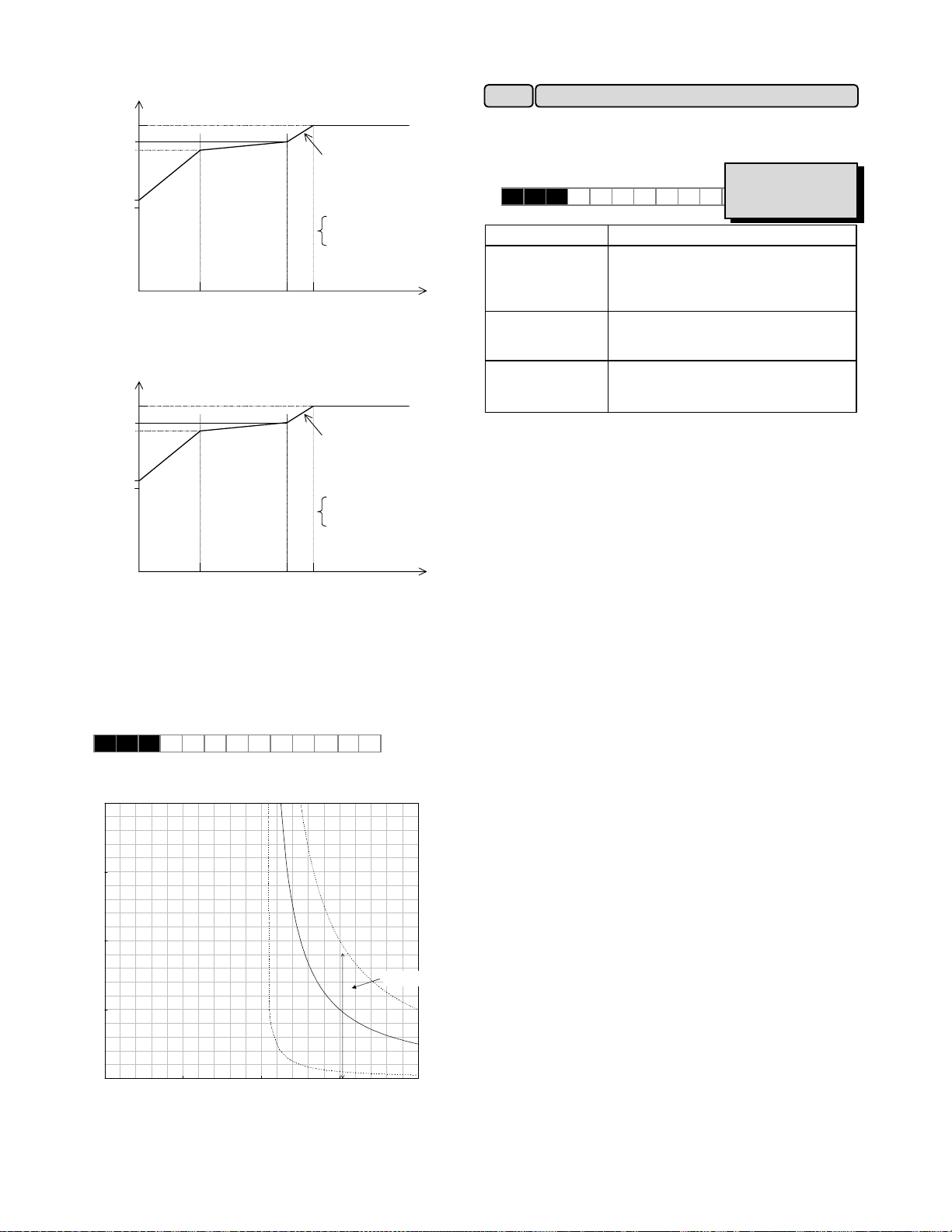
(
)
(
)
(%)
100
90
85
75HP to 125HP
110kW or above
When F10 = 1
F13
This function controls the frequent use and continuous
operating time of the braking resistor to prevent the
resistor from overheating.
F 1 3 DBR O L
Inverter capacity Operation
Operation level current (%)
53
fe= fb (fb
60Hz (fb
fb:
60Hz)
<
≥60Hz)
Base frequency
G11S: 10HP or less
Fe x 0.33
Operation level current and output frequency
Fe x 0.83
fe
Output frequency f0 (Hz)
P11S: 15HP or less
(%)
100
90
85
150HP or above
110kW or above
When F10 = 1
G11S: 15HP or more
P11S: 20HP or more
XWhen the setting value is selected to "2", the type of
braking resistor and connection circuit are set by U59.
Electric thermal O/L relay (for breaking resistor)
Related functions:
0: Inactive
1: Active (built-in braking resistor)
2: Active
(DB***-2C/4C external braking resistor)
0: Inactive
2: Active
(DB***-2C/4C external braking resistor)
0: Inactive
U59
The details are referred to the function : U59.
Operation level current (%)
53
fe= fb (fb
60Hz (fb
fb:
60Hz)
<
≥60Hz)
Base frequency
Fe x 0.33
Fe x 0.83
fe
Output frequency f0 (Hz)
Operation level current and output frequency
XThe time from when 150% of the operation level
current flows continuously to when he electronic
thermal O/L relay activates can be set.
The setting range is 0.5 to 75.0 minutes (in 0.1
minute steps).
F 1 2 T I M E C N S T 1
Current-Operation time Characteristics
20
15
10
Operation time(min)
5
changed by F12
F12=10
F12=5
0
0 50 100 150 200
(output current/operation level current)
x 100(%)
F12=0.5
5-12
Page 62

F14
Restart mode after momentary power failure
XThis function selects operation if a momentary power failure occurs.
The function for detecting power failure and activating protective operation (i.e., alarm output, alarm display, inverter
output cutoff) for undervoltage can be selected. The automatic restart function (for automatically restarting a coasting
motor without stopping) when the supply voltage is recovered can also be selected.
XWhen setting value is selected "2" or "3", both integration constant and the proportional constant during operation
ride-though can be adjusted by the function code : U23 and U24. The details are referred to the function code : U23 and
U24.
F 1 4 R E S T A R T
Related functions:
U23, U24
Setting range: 0 to 5
The following table lists the function details.
Set
value
0
1
2
3
4
5
Function name Operation at power failure Operation at power recovery
Inactive
(immediate inverter trip)
Inactive
(inverter trip at recovery)
Inactive
(inverter trip after
deceleration to a stop at
power failure)
Active
(operation ride through,
for high-inertia loads)
Active
(restart with the
frequency at power
failure)
Active
(restart with the start
frequency, for low-inertia
loads)
Note1
Note1
Note1
If undervoltage is detected, the drive will immediately trip and
an undervoltage fault (LU) is displayed. The drive output
stops and the motor will coast to a stop.
If undervoltage is detected, the drive output stops and the
motor will immediately coast to a stop. A drive fault is not
activated
When the DC bus voltage reaches the continue operation
voltage level (H15), a controlled deceleration to a stop occurs.
The inverter collects the inertia energy of the load to maintain
the DC bus voltage and controls the motor until it stops, then
an undervoltage fault (LU) is activated.
The drive will automatically decrease the deceleration time if
necessary. If the amount of inertia energy from the load is
small, and the undervoltage level is achieved before the motor
stops, the undervoltage fault is immediately activated and the
motor will coast to a stop.
When the DC bus voltage reaches the continue operation
voltage level (H15), energy is collected from the inertia of the
Note1
load to maintain the DC bus voltage and extend the ride
through time. The drive will automatically adjust the
deceleration rate to maintain DC bus voltage level. If
undervoltage is detected, the protective function is not
activated, but drive output stops and the motor coast to a
stop.
If undervoltage is detected, the protective function is not
activated. The drive output stops and the motor will coast to a
stop.
If undervoltage is detected, the protective function is not
activated, but output stops.
The drive operation is not automatically
restarted. Input a reset command and
operation command to restart operation.
An undervoltage fault (LU) is activated at
power recovery. Drive operation is not
automatically restarted. Input a reset
command to restart operation.
The drive operation is not automatically
restarted. Input a reset command and
operation command to restart operation.
Operation is automatically restarted.
For power recovery during ride-through the
drive will accelerate directly to the original
frequency. If undervoltage is detected,
operation automatically restarts with the
frequency at the time that the undervoltage
is detected.
Operation is automatically restarted with
the frequency at power failure.
Operation is automatically restarted with
the frequency set by F23, "Starting
frequency."
Note1) When the function code H18(Torque control) is excluding "0" and Motor 1 is selected, the inverter will trip at power
recovery if function code F14 is set to between "2" and "5". This operation is same as F14 is set to "1".
Function codes H13 to H16 are provided to control a restarting operation after momentary power failure. These functions
should be understood and used. The pick-up (speed search) function can also be selected as a method of restarting when
power is recovered following a momentary failure. (For setting details, see function code H09.)
The pick-up function searches for the speed of the coasting motor to restart the motor without subjecting it to excessive shock.
In a high-inertia system, the reduction in motor speed is minimal even when the motor is coasting. A speed searching time is
required when the pick-up function is active. In such a case, the original frequency may be recovered sooner when the function
is inactive and the operation restarted with the frequency prior to the momentary power failure.
The pick-up function works in the range of 5 to 100 Hz. If the detected speed is outside this range, restart the motor using the
regular restart function.
• Automatically restart could be provided at power recovered, if "Restart mode after
WARNING
momentary power failure" is valid.
• The machine should be designed to securing the human safe even restarting.
Accident may result.
5-13
Page 63

Set value : 0
Main circuit DC
voltage
Power failure
Power recovery
Under voltage
Set value : 3
Main circuit DC
voltage
Power failure Power recovery
H15
Operation continuation level
Output
frequency
LV trip
Set value : 1
Main circuit DC
voltage
Output
frequency
LV trip
Set value : 2
Main circuit DC
voltage
Output
frequency
ON
Under voltage
ON
H15
Operation continuation level
Time
Time
Time
Output
frequency
(motor speed)
LV trip
Set value : 4
Main circuit DC
voltage
Output
frequency
(motor speed)
LV trip
IPF
(terminals
Y1 to Y5)
Set value : 5
Main circuit DC
voltage
Under voltage
H13:Waiting time
Under voltage
ON
Synchroni zation
Acceleration
LV trip
ON
Output
frequency
(motor speed)
LV trip
H13:Waiting time
Note : Dotted-dashed lines indicate motor speed.
5-14
Page 64

A
F16 Frequency limiter (Low)
XThis function sets the upper and lower limits for the
setting frequency .
F 1 5 H L I M I T E R
F 1 6 L L I M I T E R
Setting range G11S: 0 to 400Hz
P11S: 0 to 120Hz
+ Maximum frequency
Frequency limiter (High) F15
Set frequency
Upper limit value
Upper limit value
-
100%
Lower limit value
Lower limit value
+100%
Set frequency
※ The inverter output starts with the start frequency
when operation begins, and stops with the stop
frequency when operation ends.
※ If the upper limit value is less than the lower limit value,
the upper limit value overrides the lower limit value.
※ When lower limit value is set, the inverter operates
with lower limit value at operation command is "ON"
even frequency command is zero(0Hz).
F17 Gain
XThis function sets the rate of the set frequency value
to analog input.
F 1 7 F R E Q G A I N
Operation follows the figure below.
Set frequency value
- Maximum frequency
200%
+Maximum
frequency
100%
50%
Analog input
-10 0 +10[V]
20[mA]
4
+10V terminal 12
20mA terminal C1
F18 Bias frequency
XThis function adds a bias frequency to the set
frequency value to analog input.
F 1 8 FREQ B I A S
Setting range G11S: -400.0 to +400.0Hz
P11S: -120.0 to +120.0Hz
The operation follows the figure below.
When the bias frequency is higher than the maximum
frequency or lower than the - maximum frequency, it is
limited to the maximum or - maximum frequency.
Set frequency value
+Maximum
frequency
-10 0 +10[V]
4 20[mA]
-Maximum
frequency
※ Reversible operation is valid if the function code
F01/C30 is set to "4" or "5" only.
※ This function is invalid if PID control is selected(H20 is
"1" or "2").
F20 DC brake (starting frequency)
F21
F22
XStarting frequency: This function sets the frequency
Setting range: 0 to 60Hz
XOperation level: This function sets the output current
Setting range G11S: 0 to 100%
P11S: 0 to 80%
XTime: This function sets the time of a DC injection
Setting range 0.0: Inactive
DC brake (Braking level)
DC brake (Braking time)
with which to start a DC injection brake to decelerate
the motor to a stop.
F 2 0 D C B R K H z
level when a DC injection brake is applied. Set a
percentage of inverter rated output current in 1%
steps.
F 2 1 D C B R K L V L
brake operation.
F 2 2 D C B R K t
0.1 to 30.0 seconds
Bias frequency
(when positive)
Bias frequency
(when negative)
nalog input
+10V terminal 12
20mA terminal C1
CAUTION
-Maximum
frequency
5-15
Do not use the inverter brake function for
mechanical holding.
Injury may result.
Page 65

F23
F24
F25 Stop frequency
Starting frequency (frequency)
Start frequency (Holding time)
The starting frequency can be set to reserve the torque at
startup and can be sustained until the magnetic flux of the
motor is being established.
XFrequency: This function sets the frequency at startup.
F 2 3 S T A R T H z
Setting range: 0.1 to 60Hz
XHolding time: This function sets the holding time during
which the start frequency is sustained at startup.
F 2 4 H O L D I N G t
Set values: 0.1 to 10.0 seconds
∗The holding time does not apply at the time of switching
between forward and reverse.
∗The holding time is not included in the acceleration time.
∗The holding time also applies when pattern operation (C21)
is selected. The holding time is included in the timer value.
XThis function sets the frequency at stop.
F 2 5 S T O P H z
Setting range: 0.0 to 60.0Hz
Output frequency
Starting frequency
Stopping frequency
The operation does not start when the starting frequency
is less than the stopping frequency or when the setting
frequency is less than the stopping frequency.
F26 Motor sound (carrier frequency)
XThis function adjusts the carrier frequency, correct
adjustment of which prevents resonance with the
machine system, reduces motor and inverter noise, and
also reduces leakage current from output circuit wiring.
F 2 6 M T R S O U N D
Nominal applied motor Setting range
75HP or less 0.75 to 15kHz
G11
100HP or more 0.75 to 10kHz
30HP or less 0.75 to 15kHz
P11
40HP to 100HP 0.75 to 10kHz
125HP or more 0.75 to 6kHz
Carrier frequency Low High
Motor noise High Low
Output current waveform
Leakage current
Noise occurrence Extremely low High
Notes:
1. Reducing the set value adversely affects the output
current waveform (i.e., higher harmonics), increases
motor loss, and raises motor temperature. For example,
at 0.75kHz, reduce the motor torque by about15%.
2 Increasing the set value increases inverter loss and raises
inverter temperature.
Holding time
Forward rotation
Time
Bad Good
Small amount Large amount
F27 Motor sound (sound tone)
XThe tone of motor noise can be altered when the carrier
frequency is 7kHz or lower. Use this function as
required.
F 2 7 MT R T O N E
Setting range: 0 , 1, 2 , 3
F30 FMA (voltage adjust)
FMA (function) F31
Monitor data (e.g.,output frequency, output current) can
be output to terminal FMA as a DC voltage. The amplitude
of the output can also be adjusted.
XThis function adjusts the voltage value of the monitor
item selected in F31 when the monitor amount is 100%.
A value from 0 to 200 (%) can be set in 1% steps.
F 3 0 FMA V - A D J
Setting range: 0 to 200%
Higher than 10V
10V
F30:200%
F30:100%
5V
F30:50%
FMA terminal outputvoltage
F30:0%
100%50%
XThis function selects the monitor item to be output to
terminal FMA.
F 3 1 F M A F U N C
Set
Monitor item
Definition of 100% monitor amount
value
0 Output frequency 1
Maximum output frequency
(before slip compensation)
1 Output frequency 2
Maximum output frequency
(after slip compensation)
2 Output current Rated output current of
inverter x 2
3 Output voltage 230V series: 250V
460V series: 500V
4 Output torque Rated torque of motor x 2
5 Load rate Rated load of motor x 2
6 Power consumption Rated output of inverter x 2
7 PID feedback amount Feedback amount of 100%
8 PG feedback amount
(only when option is installed)
Synchronous speed at
maximum frequency
9 DC link circuit voltage 230V series: 500V
460V series: 1,000V
10 Universal AO
0 to 10V output through
communication and not related to
inverter operation.
※The power consumption shows "0" during regenerative load.
5-16
Page 66

V
MAX
F33 FMP (pulse rate)
FMP (voltage adjust) F34
FMP terminal (function) F35
Monitor data (e.g.,output frequency, output current) can
be output to terminal FMP as pulse voltage. Monitor
data can also be sent to an analog meter as average
voltage.
When sending data to a digital counter or other
instrument as pulse output, set the pulse rate in F33 to
any value and the voltage in F34 to 0%.
When data is sent to an analog meter or other instrument
as average voltage, the voltage value set in F34
determines the average voltage and the pulse rate in F33
is fixed to 2670 (p/s).
XThis function sets the pulse frequency of the monitor
item selected in F35 within a range of 300 to 6000 (p/s)
in 1 p/s steps.
F 3 3 F M P P U L S E S
Setting range: 300 to 6,000 p/s
T1
About 15.6V
0
VL:0.5V
Pulse cycle time
T
Pulse frequency (p/s) = 1/T
Duty (%) = T1/T x 100
Average voltage (V) = 15.6 x T1/T
The output terminal of the FMP terminal is composed of
the transistor, therefore there is a saturation voltage
MAX
(0.5V
). When using in the analogue by the filter
processing the pulse voltage, it should be make a 0V
adjustment by external equipment.
XThis function sets the average voltage of pulse output to
terminal FMP.
F 3 4 F M P V - A D J
Setting range
0%: The pulse rate varies depending on the
monitor amount of the monitor item
selected in F35. (The maximum value is
the value set in F33. The pulse duty is fixed
at 50%.)
1 to 200%: Pulse rate is fixed at 2,670 p/s. The
average voltage of the monitor item
selected in F35 when the monitor amount
is 100% is adjusted in the 1 to 200% range
(1% steps).
(The pulse duty varies.)
XThis function selects the monitor item to be output to
terminal FMP.
F 3 5 F M P F U N C
The set value and monitor items are the same as those
of F31.
F36 30Ry operation mode
XThis function specifies whether to activate (excite) the
alarm output relay (30Ry) for any fault at normal or
alarm status.
F 3 6 30 RY M O D E
Set
Operation
value
0
1
At normal 30A - 30C: OFF, 30B - 30C: ON
At abnormal 30A - 30C: ON, 30B - 30C:OFF
At normal 30A - 30C:ON, 30B - 30C: OFF
At abnormal 30A - 30C: OFF, 30B - 30C: ON
XWhen the set value is 1, contacts 30A and 30C are
connected when the inverter control voltage is
established (about one second after power on).
XWhen the power is off, contacts 30A and 30C are OFF;
30B and 30C are ON.
30A
30B
30C
F40 Torque limiter 1 (driving)
30
F41 Torque limiter 1 (braking)
XThe torque limit operation calculates motor torque from
the output voltage, current and the primary resistance
value of the motor, and controls the frequency so the
calculated value does not exceed the limit. This operation
enables the inverter to continue operation under the limit
even if a sudden change in load torque occurs.
XSelect limit values for the driving torque and braking
torque.
XWhen this function is activated, acceleration and
deceleration operation times are longer than the set values.
XThe motor tuning (P04 / A13) should be set to "2" for
this function is valid.
XThe increase frequency upper bound during torque limit
operation is set by function code : U01.
XWhen the setting value is selected "0" (prevent OU trip),
the operation mode is selected by function code : U60.
The details are referred to the functions : U01, U60.
Related functions:
U01, U60
F 4 0 DRV T R Q 1
F 4 1 BRK T R Q 1
Function Setting range Operation
Torque
limit
G11S:20% to 200%
P11S:20% to 150%
The torque is limited to the set
value.
(driving)
Torque
limit
999 Torque limiting inactive
G11S:20% to 200%
P11S:20% to 150%
The torque is limited to the set
value.
(braking)
0 Prevents OU trip due to
power regeneration effect
automatically.
999 Torque limiting inactive
5-17
Page 67

WARNING
When the torque limit function is selected, an operation may
not match the set acceleration and deceleration time or set
speed. The machine should be so designed that safety is
ensured even when operation does not match set values.
Accident may result.
WARNING
Output frequency can't be lower by reducing U01:
Maximum compensation frequency during braking limit or
F15: High frequency limit, during braking limit condition
which output frequency is increasing. Set U01 or F15
when braking torque limit is not active.
Accident may result.
F42
XThis is a function for motor 1.
XTo obtain the motor torque most efficiently, the torque
vector control calculates torque according to load, to
adjust the voltage and current vectors to optimum
values based on the calculated value.
F 4 2 T R Q V E C T O R 1
Set value Operation
0 Inactive
1 Active
XWhen 1 (Active) is set, the set values of the following
functions differ from the written values:
c F09 Torque boost 1
Automatically set to 0.0 (automatic torque boosting).
d P09 Slip compensation amount Slip compensation is
automatically activated.
When 0.0 is set, the amount of slip compensation for
the FUJI standard 3-phase motor is applied.
Otherwise, the written value is applied.
XUse the torque vector control function under the
following conditions:
c There must be only one motor.
Connection of two or more motors makes accurate
control difficult.
dThe function data (rated current P03, no-load current
P06, %R1 P07, and %X P08) of motor 1 must be
correct.
When the standard FUJI 3-phase motor is used, setting the
capacity (function P02) ensures entry of the above data. An
auto tuning operation should be performed for other motors.
eThe rated current of the motor must not be significantly
less than the rated current of the inverter. A motor two
ranks lower in capacity than the nominal applied motor
for the inverter should be used at the smallest
(depending on the model).
fTo prevent leakage current and ensure accurate control,
the length of the cable between the inverter and motor
should not exceed 164ft(50m).
gWhen a reactor is connected between the inverter and
the motor and the impedance of the wiring cannot be
disregarded, use P04, "Auto tuning," to rewrite data.
Torque vector control 1
Related functions:
P01, P09
If these conditions are not satisfied, set 0 (Inactive).
5-18
Page 68
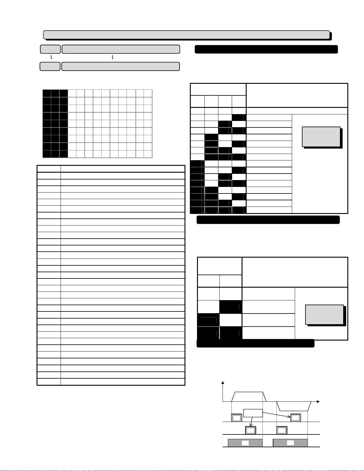
E:Extension Terminal Functions
E01
~
E09
X1 Terminal function
~
X9 Terminal function
Each function of digital input terminals X1 to X9 can be
set as codes.
E 0 1 X 1 F U N C
E 0 2 X 2 F U N C
E 0 3 X 3 F U N C
E 0 4 X 4 F U N C
E 0 5 X 5 F U N C
E 0 6 X 6 F U N C
E 0 7 X 7 F U N C
E 0 8 X 8 F U N C
E 0 9 X 9 F U N C
Set value
0,1,2,3
4,5
10
11
12
13
14
15
16
17
18
19
20
21
22
23
24
25
26
27
28
29
30
31
32
33
34
35
Multistep frequency selection (1 to 15 steps) [SS1],[SS2],[SS4],[SS8]
Acceleration and deceleration time selection (3 steps) [RT1],[RT2]
Self-hold selection [HLD]
6
Coast-to-stop command [BX]
7
Alarm reset [RST]
8
External alarm [THR]
9
Jogging [JOG]
Frequency setting 2/frequency setting 1 [Hz2/Hz1]
Motor 2/motor 1 [M2/M1]
DC injection brake command [DCBRK]
Torque limit 2/torque limit 1 [TL2/TL1]
Switching operation from line to inverter (50Hz) [SW50]
Switching operation from line to inverter (60Hz) [SW60]
UP command [UP]
DOWN command [DOWN]
Edit permission command (data change permission) [WE-KP]
PID control cancellation [Hz/PID]
Forward/inverse switching (terminals 12 and C1) [IVS]
Interlock (52-2) [IL]
Torque control cancellation [Hz/TRQ]
Link operation selection (Standard:RS-485, Option: BUS) [LE]
Universal DI [U-DI]
Start characteristics selection [STM]
PG-SY enable ( Option ) [PG/Hz]
Synchronization command ( Option ) [SYC]
Zero speed command with PG option [ZERO]
Forced stop command [STOP1]
Forced stop command with Deceleration time 4 [STOP2]
Pre-exiting command with PG option [EXITE]
Line speed control Cancellation [Hz/LSC]
Line speed frequency memory [LSC-HLD]
Frequency setting 1 / Frequency setting 2 [Hz1/Hz2]
Note: Data numbers which are not set in the functions
from E01 to E09, are assumed to be inactive.
Function
Multistep frequency selection [SS1][SS2][SS4][SS8]
The frequency can be switched to a preset frequency in function
codes C05 to C19 by switching the external digital input signal.
Assign values 0 to 3 to the target digital input terminal. The
combination of input signals determines the frequency.
Combination of set
value input signals
3
[SS8]2 [SS4]1 [SS2]0 [SS1]
off off off off
off off off on
off off on off
off off on on
off on off off
off on off on
off on on off
off on on on
on off off off
on off off on
on off on off
on off on on
on on off off
on on off on
on on on off
on on on on
Acceleration and deceleration time selection [RT1][RT2]
Assigned by F01 or C30
C05 MULTI Hz-1
C06 MULTI Hz-2
C07 MULTI Hz-3
C08 MULTI Hz-4
C09 MULTI Hz-5
C10 MULTI Hz-6
C11 MULTI Hz-7
C12 MULTI Hz-8
C13 MULTI Hz-9
C14 MULTI Hz-10
C15 MULTI Hz-11
C16 MULTI Hz-12
C17 MULTI Hz-13
C18 MULTI Hz-14
C19 MULTI Hz-15
The acceleration and deceleration time can be switched to
a preset time in function codes E10 to E15 by switching the
external digital input signal. Assign values 4 and 5 to the
target digital input terminal. The combination of input
signals determines the acceleration and deceleration times.
Combination of
set value input
signals
Acceleration and deceleration times selected
5
[RT2]4 [RT1]
off off
off on
on off
on on
3-wire operation stop command [HLD]
F07 ACC TIME1
F08 DEC TIME1
E10 ACC TIME2
E11 DEC TIME2
E12 ACC TIME3
E13 DEC TIME3
E14 ACC TIME4
E15 DEC TIME4
This selection is used for 3-wire operation. The FWD or REV
signal is self-held when [HLD] is on, and the self-hold is
cleared when [HLD] is turned off. To use this [HLD] terminal
function, assign 6 to the target digital input terminal.
Output
frequency
Forward
rotation
Frequency selected
Reverse
rotation
Related function
C05 to C19
Setting range
G11S:0.00 to 400.00Hz
P11S:0.00 to 120.00Hz
Setting range
0.01 to 3600s
Related function
~F08
F07
~E15
E10
Ignore
FWD
REV
HLD
5-19
ON
ON ON
ON
ON
ON
Page 69

Coast-to-stop command [BX]
When BX and CM are connected, inverter output is cut off
immediately and the motor starts to coast-to-stop. An
alarm signal is neither output nor self-held. If BX and CM
are disconnected when the operation command (FWD or
REV) is on, operation starts at the start frequency. To
use this BX terminal function, assign value "7" to the
target digital input terminal.
Output
Frequency
FWD
REV
BX
Forward
rotation
Ignored
Forward
rotation
ON
Forward
rotation
ON ON
ON ON
Alarm reset [RST]
When an inverter trip occurs, connecting RST and CM
clears the alarm output (for any fault) ; disconnecting
them clears trip indication and restarts operation. To
use this RST terminal function, assign value "8" to the
target digital input terminal.
External fault [THR]
Disconnecting THR and CM during operation cuts off
inverter output (i.e., motor starts to coast-to-stop) and
outputs alarm OH2, which is self-held internally and
cleared by RST input. This function is used to protect an
external brake resistor and other components from
overheating. To use this THR terminal function, assign
value "9" to the target digital input terminal. ON input is
assumed when this terminal function is not set.
Jogging operation[JOG]
This function is used for jogging (inching) operation to
position a work piece. When JOG and CM are
connected, the operation is performed with the jogging
frequency set in function code C20 while the operation
command (FWD-CM or REV-CM) is on. To use this
JOG terminal function, assign value "10" to the target
digital input terminal.
Note: It is possible to change to the JOG operation by
keypad panel when keypad panel operation.
JOG
Input
Operation
command
(FWD/REV)
Operation
mode
ON
ON
JOG
OPR.
OFF
OFF
STOP RUN STOP
ON
RUN
JOG
OPR.
OFF
STOP
ON
ON
RUN
NOR.
OPR.
OFF
OFF
STOP
ON
RUN
NOR.
OPR.
WARNING
- When the JOG command and operation command
(FWD/REV) are input at the same time, it can NOT be
changed to the JOG operation. It operates with setting
frequency.
- When the JOG operation is used, it should be input the
operation command after input the JOG command during
the inverter is STOP.
- When the JOG command and operation command are
input at the same time, the JOG command is assigned to
the "Multistep frequency selection (SS1 to SS8)" and
used it.
- The inverter can NOT be stopped and JOG operation is
continued even JOG command is OFF during JOG
operation. The inverter is deceleration to a stop if the
operation command is OFF.
Accident may result.
Frequency setting 2/frequency setting 1 [Hz1/Hz2]
This function switches the frequency setting method set in
function codes F01 and C30 by an external digital input
signal.
Set value input signal
11
off
on
Note: It can not be used with set value "35"
simultaneously. When the set value "11" and "35" are
selected, "Er6" is displayed.
Motor 2/motor 1 [M1/M2]
This function switches motor constants using an external
digital input signal.
This input is effective only when the operation command
to the inverter is off and operation has stopped and does
not apply to the operation at 0Hz.
Set value input signal
12
off
on
DC brake command [DCBRK]
When the external digital input signal is on, DC injection
braking starts when the inverter's output frequency drops
below the frequency preset in function code F20 after the
operation command goes off. (The operation command
goes off when the key is pressed at keypad panel
operation and when both terminals FWD and REV go on
or off at terminal block operation.) The DC injection
braking continues while the digital input signal is on. In
this case, the longer time of the following is selected:
- The time set in function code F22.
- The time which the input signal is set on.
Set value input signal
13
off
on
Frequency setting method selected
F01 FREQ CMD1
C30 FREQ CMD2
Motor selected
Related function
A01~A18
Motor 1
Motor 2
STOP
Operation selected
No DC injection brake command is given.
A DC injection brake command is given.
5-20
Page 70

Torque limit 2/torque limit 1 [TL2/TL1]
This function switches the torque limit value set in
function codes F40 and F41, and E16 and E17 by an
external digital input signal.
Set value input signal
14
off
on
Switching operation between line and inverter (50Hz) [SW50]
Torque limit
value selected
F40 DRV TRQ1
F41 BRK TRQ1
E16 DRV TRQ2
E17 BRK TRQ2
Related function
F40~F41
E16~E17
Setting range
DRV 20 to 200% ,999
BRK 0, 20 to 200% ,999
Motor operation can be switched from 50Hz commercial
power operation to inverter operation without stopping the
motor by switching the external digital input signal.
Set value
input signal
Function
15
off→on
on→off
Switching operation between line and inverter (60Hz) [SW60]
Inverter operation to line operation (50Hz)
Line operation to inverter operation (50Hz)
Motor operation can be switched from 60Hz commercial
power operation to inverter operation without stopping the
motor by switching the external digital input signal.
Set value
input signal
Function
16
off→on
on→off
Inverter operation to line operation (60Hz)
Line operation to inverter operation (60Hz)
XWhen the digital input signal goes off, 50 or 60 Hz is
output according to the set value input signal after the
restart waiting time following a momentary power failure
(function code H13). The motor is then directed to
inverter operation.
WARNING
- After the LU(Low Voltage) trip is occurred and reset it,
the inverter will automatically restart because the
operation command is kept by internal sequence.
Accident may result.
UP command [UP]/DOWN command [DOWN]
When an operation command is input (on), the output
frequency can be increased or decreased by an external
digital input signal.
The change ranges from 0 to maximum frequency.
Operation in the opposite direction of the operation
command is not allowed.
Related function
F01, C30
Related function
E01~E09
(set value: 11, 35)
Combination of set
value input signals
18 17
off off
off on
Holds the output frequency.
Increases the output frequency
Function selected
(when operation command is on)
according to the acceleration time.
on off
Decreases the output frequency
according to the deceleration time.
on on
Holds the output frequency.
There are the two types of UP/DOWN operations as
shown below. Set the desired type by setting the
frequency (F01 or C30).
XThe data "8: UP/DOWN 1" is valid only when the Motor
2 is selected.
Frequency
setting
(F01 or C30)
Initial value
at power
input on
Operation command reentry
during deceleration
Operates at the frequency at reentry.
8
(UP/DOWN1)
0Hz
Frequency
FWD ON
(REV) OFF
Returns to the frequency before
9
(UP/DOWN2)
Previous
frequency
deceleration
Frequency
FWD ON
(REV) OFF
Write enable for KEYPAD [WE-KP]
This function allows the data to be changed only when an
external signal is being input, thereby making it difficult to
change the data.
19
off
on
Function selected
Inhibit data changes.
Allow data changes.
Note:
If a terminal is set to value 19, the data becomes unable
to be changed. To change the data, turn on the terminal
and change the terminal setting to another number.
PID control cancel [Hz/PID]
The PID control can be disabled by an external digital
input signal.
Set value
input signal
Function selected
Related function
20
off
on
(frequency setting from keypad panel).
Enable PID control.
Disable PID control
H20~H25
5-21
Page 71

A
Inverse mode changeover [IVS]
The analog input (terminals 12 and C1) can be switched
between forward and inverse operations by an external
digital input signal.
Set value
input signal
Function selected
Related function
F01, C30
21
off
on
Forward operation when forward
operation is set and vice versa
Inverse operation when forward
operation is set and vice versa
XThis function is invalid when the PID control is
selected(H20: 1 or 2).
Interlock signal (52-2) [IL]
When a contactor is installed on the output side of the
inverter, the contactor opens at the time of a momentary
power failure, which hinders the reduction of the DC
circuit voltage and may prevent the detection of a power
failure and the correct restart operation when power is
recovered. The restart operation at momentary power
failure can be performed effectively with power failure
information provided by an external digital input signal.
Set value
input signal
Function selected
Related function
F14
22
off
No momentary power failure detection
operation by digital input
on
Momentary power failure detection
operation by digital input
Torque control cancel [Hz/TRQ]
When function code H18 (torque control function
selection) is set to be active (value 1 or 2), this operation
can be canceled externally
Assign value "23" to the target digital input terminal and
switch between operation and no operation in this input
signal state.
Set value
input signal
Function selected
Related function
H18
23
Torque control function active
off
The input voltage to terminal 12 is the
torque command value.
Torque control function inactive
The input voltage to terminal 12 is the
on
frequency command value.
PID feedback amount when PID control
operation is selected (H20 = 1 or 2).
WARNING
- The motor speed may be changed quickly when the
"Torque control cancel" is changed to ON or OFF
because of changing the control.
Accident may result.
Link enable (RS-485 standard, BUS) [LE]
Frequency and operation commands from the link can be
enabled or disabled by switching the external digital input
signal. Select the command source in H30, "Link function."
Assign value "24" to the target digital input terminal and
enable or disable commands in this input signal state.
Set value
input signal
Function selected
Related function
H30
24
off
on
Universal DI (U-DI)
Link command disabled.
Link command enabled.
Assigning value "25" to a digital input terminal renders the
terminal a universal DI terminal. The ON/OFF state of
signal input to this terminal can be checked through the
RS-485 and BUS option.
This input terminal is only used to check for an incoming
input signal through communication and does not affect
inverter operation.
Pick up start mode [STM]
The start characteristics function (pick-up mode) in
function code H09 can be enabled or disabled by
switching the external digital input signal. Assign value
"26" to the target digital input terminal and enable or
disable the function in this input signal state.
Set value
input signal
Function selected
Related function
H09
26
off
on
Zero speed command with PG option [ZERO]
Pre-exiting command with PG option [EXITE]
Start characteristic function disabled
Start characteristic function enabled
PG-SY enable ( Option ) [PG/Hz]
These functions are used for PG-Option or
SY-Option card. Refer to each instruction manual.
Forced stop command with Deceleration [STOP1]
Forced stop command with Deceleration time 4 [STOP2]
Normally this terminal should be “ON”, when this terminal
goes off during motor running, the motor decelerates to
stop, and outputs alarm “Er6 “. When the inverter is stop
by STOP1/STOP2 signal, the signal should be kept on
4ms or longer.
In case of terminal [STOP2], the deceleration time is
determined by E15( DEC TIME4).
This function is prioritized under any operation (Terminal.
Keypad, Communication...operation). However when the
torque limiter/regeneration avoidance at deceleration is
selected, the time which is set by deceleration time may
be longer.
Output
Frequency
FWD or REV
[STOP1] or
[STOP2]
ON
In case of [STOP2],
time is fixed by E15
(EDC TIME4)
ONON
ON
larm
5-22
Er6
Page 72

Line speed control Cancellation [Hz/LSC]
Line speed frequency memory [LSC-HLD]
XThese functions are used for OPC-G11S-PG and PG2.
Refer to each instruction manual.
Frequency setting 1 / Frequency setting 2 [Hz1/Hz2]
XThis function switches the frequency setting method
set in function codes F01 and C30 by an external
digital input signal.
This is the reverse-logic of setting value
"11"(Frequency setting 2/Frequency setting 1
[Hz2/Hz1]).
Set value input signal
35
off
on
Frequency setting method selected
C30 FREQ CMD2
F01 FREQ CMD1
Note: It can not be used with set value "11"
simultaneously. When the set value "11" and "35" are
selected, "Er6" is displayed.
Settings when shipped from the factory
Digital
input
Setting at factory shipment
Set
Description
value
Terminal X1
Terminal X2
Terminal X3
Terminal X4
Terminal X5
0 Multistep frequency selection [SS1]
1 Multistep frequency selection [SS2]
2 Multistep frequency selection [SS4]
3 Multistep frequency selection [SS8]
4
Acceleration and deceleration selection
[RT1]
Terminal X6
5
Acceleration and deceleration selection
[RT2]
Terminal X7
Terminal X8
Terminal X9
E10 Acceleration time 2
E11 Deceleration time 2
6 Self-hold selection [HLD]
7 Coast-to-stop command [BX]
8 Alarm reset [RST]
E12 Acceleration time 3
E13 Deceleration time 3
E14 Acceleration time 4
E15 Deceleration time 4
XAcceleration time 1 (F07) and deceleration time 1 (F08)
as well as three other types of acceleration and
deceleration time can be selected.
XThe operation and setting ranges are the same as those
of acceleration time 1 and deceleration time 1. See
explanations for F07 and F08.
XFor switching acceleration and deceleration times, select
any two terminals from terminal X1 (function selection) in
E01 to terminal X9 (function selection) in E09 as
switching signal input terminals. Set "4" (acceleration
and deceleration time 1) and "5" (acceleration and
deceleration time 2) to the selected terminals and input a
signal to each terminal to switch acceleration and
deceleration times. Switching is possible during
acceleration, deceleration, or constant-speed operation.
E 1 0 ACC T I M E 2
E 1 1 DEC T I M E 2
E 1 2 ACC T I M E 3
E 1 3 DEC T I M E 3
E 1 4 ACC T I M E 4
E 1 5 DEC T I M E 4
Related functions
E01 to E09
(Set values:14)
XExample: When 4 and 5 are set to terminals X2 and X3:
Operation
FWD
(REV)
X2
X3
CM
Output
frequency
Accel
time
1
ON
Decel
time
1
Accel
time
2
ON
Decel
time
2
Accel
time
3
ON
Decel
time
3
Accel
time
4
Decel
time
4
E16
Torque limiter 2 (driving)
Torque limiter 2 (braking) E17
XThis function is used to switch the torque limit level set
in F40 and F41 by an external control signal. Input
an external signal by selecting any of the control input
terminals (X1 to X9) as torque limit 2/torque limit 1
(value 14) in E01 to E09.
XThe motor tuning (P04 / A13) should be set to "2" for
this function is valid.
XMaximum compensation frequency during braking torque limit
is set by U01.
Related functions
U01
U60
XThe operation mode is set by U60 when the setting
value is "0%: Regeneration avoidance at
deceleration".
The detail is referred to the U01, U60.
Related functions
E01~E09
(Set value: 14)
E 1 6 DRV T R Q 2
E 1 7 BRK T R Q 2
Time
Maximum
frequency
5-23
Page 73

A
E20
~
E24
XSome control and monitor signals can be selected and
output from terminals [Y1] to [Y5]. Terminals [Y1] to
[Y4] use transistor output; terminals[Y5A] and [Y5C]
use relay contacts.
E 2 0 Y 1 F U N C
E 2 1 Y 2 F U N C
E 2 2 Y 3 F U N C
E 2 3 Y 4 F U N C
E 2 4 Y 5 F U N C
Set
Output signal
value
0 Operating [RUN]
1 Frequency arrival [FAR]
2 Frequency detection [FDT1]
3 Stopping due to undervoltage [LV]
4 Torque polarity detection [B/D]
5 Torque limiting [TL]
6 Restarting after momentary power failure [IPF]
7 Overload early warning [OL1]
8 During keypad panel operation [KP]
9 Inverter stopping [STP]
10 Ready for operation [RDY]
11
Operation switching between line and inverter [SW88]
12
Operation switching between line and inverter [SW52-2]
13
Operation switching between line and inverter [SW52-1]
14 Motor 2 switching [SWM2]
15 Terminal AX function [AX]
16 Pattern operation stage change [TU]
17 Pattern operation cycle operation completed [TO]
18 Pattern operation stage number [STG1]
19 Pattern operation stage number [STG2]
20 Pattern operation stage number [STG4]
21 Alarm detail [AL1]
22 Alarm detail [AL2]
23 Alarm detail [AL4]
24 Alarm detail [AL8]
25 Cooling fan operating [FAN]
26 Retry function operating [TRY]
27
Universal DO [U-DO]
28 Heat sink overheat early warning [OH]
Synchronization completed by synchronous operation card [SY]
29
30 Life expectancy detection signal [LIFE]
31 2nd Freq. level detection [FDT2]
32 2nd OL level detection [OL2]
33 Terminal C1 off signal [C1OFF]
Speed existence signal [DNZS] ∗
34
35
Speed agreement signal [DSAG]
36
PG error signal [PG-ABN]
37 Torque limiting (Signal with delay) [TL2]
Note: For output signals marked "∗" are used for RS-485
communication, OPC-G11S-PG / PG2 or OPC-G11S-SY.
Refer to each instruction manual.
Y1 terminal function
~
Y5A and Y5C terminal function
∗
∗
∗
Inverter running [RUN]
"Running" means that the inverter is outputting a
frequency. “RUN” signal is output as when there is output
speed (frequency). When the DC injection brake
function is active, “RUN” signal is off.
Frequency equivalence signal [FAR]
See the explanation of function code E30 (frequency
arrival [detection width]).
Frequency level detection [FDT1]
See the explanation of function codes E31 and E32
(frequency detection).
Undervoltage detection signal [LV]
If the undervoltage protective function activates, i.e.
when the main circuit DC voltage falls below the
undervoltage detection level, an ON signal is output. The
signal goes off when the voltage recovers and increases
above the detection level. The ON signal is retained
while the undervoltage protective function is activating.
Undervoltage detection level: 230V series: 200V, 460V
series: 400V.
Torque polarity [B/D]
This function determines the torque polarity calculated in
the inverter and outputs a signal indicating driving or
braking torque. An OFF signal is output for driving
torque; an ON signal is output for braking torque.
Torque limiting [TL]
When the torque limiting activates, the stall prevention
function is automatically activated to change the output
frequency. The torque limiting signal is output to lighten the
load, and also used to display overload conditions on the
monitor device. This ON signal is output during the current
or torque is limited or power regeneration is prevented.
uto-restarting [IPF]
Following a momentary power failure, this function reports
the start of the restart mode, the occurrence of an automatic
pull-in, and the completion of the recovery operation.
Following a momentary power failure, an ON signal is
output when power is recovered and a synchronization
(pull-in) operation is performed. The signal goes off
when the frequency (before power failure) is recovered.
For 0Hz restart at power recovery, no signal is output
because synchronization ends when power is recovered.
The frequency is not recovered to the frequency before
the power failure occurrence.
Overload early warning [OL1]
∗
Before the motor stops by the trip operation of an electronic
thermal O/L relay, this function outputs an ON signal when
the load reaches the overload early warning level.
Either the electronic thermal O/L relay early warning or
output current overload early warning can be selected.
For setting procedure, see “E33 Overload early warning
(operation selection)”, and "E34 Overload early warning
(operation level)."
Note: This function is effective for motor 1 only.
Keypad operation mode [KP]
An ON signal is output when operation command keys
( , and ) on the keypad panel can
be used (i.e., 0 set in "F02 Operation") to issue operation
and stop commands.
This signal is OFF when the function H30(Serial link) is
set to communication side.
STOPREVFWD
5-24
Page 74

Inverter stopping [STOP]
This function outputs an inverted signal to Running
(RUN) to indicate zero speed. An ON signal is output
when the DC injection brake function is operating.
Ready output [RDY]
This function outputs an ON signal when the inverter is
ready to operate. The inverter is ready to operate when
the main circuit and control circuit power is established
and the inverter protective function is not activating.
About one second is required from power-on to ready for
operation in normal condition.
Line/Inv changeover [SW88] [SW52-2] [SW52-1]
To perform switching operation between the line and the
inverter, the sequence prepared in the inverter can be used to
select and output signals for opening and closing the
magnetic contactors connected to the inverter. As the
operation is complex, refer to technical documentation for the
FRENIC5000G11S series when using this function.
As the sequence will operate automatically when SW88
or SW52-2 is selected, do not select when not using the
sequence.
Motor 2 /Motor 1 [SWM2]
When a signal for switching to motor 2 is input from the
terminal selected by terminals [X1] to [X9], this function
selects and outputs the signal for switching the magnetic
contactor for the motor. As this switching signal is not
output during running including when the DC injection
braking function is operating, a signal must be re-input
after output stops.
Auxiliary terminal [AX]
When an operation (forward or reverse) command is
entered, this function outputs an ON signal. When a
stop command is entered, the signal goes off after
inverter output stops. When a coast-to-stop command
is entered and the inverter protective function operates,
the signal goes off immediately.
When the pattern operation stage changes, this function
outputs a one-shot (100ms) ON signal to report a stage
change.
When the seven stages of a pattern operation are
completed, this function outputs a one-shot (100 ms) ON
signal to report the completion of all stages.
During pattern operation, this function reports the stage
(operation process) being operated.
When pattern operation is not activated (i.e., no stage is
selected), the terminals do not output a signal.
Time-up signal for pattern operation [TU]
Cycle completion signal for pattern operation [TO]
Stage No. indication for pattern operation [STG1] [STG2] [STG4]
Pattern operation
stage No.
Stage 1
Stage 2
Stage 3
Stage 4
Stage 5
Stage 6
Stage 7
Output terminal
STG1 STG2 STG4
on off off
off
on on off
off off
on off on
off
on on on
on off
on
on on
Alarm indication [AL1] [AL2] [AL4] [AL8]
This function reports the operating status of the inverter
protective function.
Alarm detail
(inverter protective function)
Overcurrent, ground fault, fuse blown
Overvoltage
Undervoltage shortage, input phase failure
Motors 1 and 2 overload
Inverter overload
Heat sink overheating, inverter inside overheating
External alarm input, braking resistor overheating
Memory error, CPU error
Keypad panel communication error, option communication error
Option error
Output wiring error
RS-485 communication error
Overspeed, PG disconnection
In normal operation terminals do not output a signal.
Fan operation signal [FAN]
When used with "H06 Cooling fan ON/OFF control," this
function outputs a signal while the cooling fan is
operating.
Auto-resetting [TRY]
When a value of 1 or larger is set to "H04 Retry
operating," the signal is output while retry operation is
activating when the inverter protective function is
activated.
Universal DO [U-DO]
Assigning value "27" to a transistor output terminal
renders the terminal a universal DO terminal.
This function enables ON/OFF through the RS-485 and
BUS option.
This function serves only to turn on and off the transistor
output through communication and is not related to
inverter operation.
Overheat early warning [OH]
This function outputs a early warning signal when heat
sink temperature is (overheat detection level - 10℃) or
higher.
Life expectancy detection signal [LIFE]
XWhen either of data for the Life expectancy judgment of
the function code:U09 to U11 reaches at the Life
expectancy judgment level, the ON signal is output.
However, the inverter does not do alarm.
Moreover, the alarm output for any fault (30A, 30B,
30C ) does not operate.
Function
code
U09
U10
U11
U59
Capacitor in main circuit 85% or less of the initial value
Electrolytic capacitor on PCB 61,000 hours
Cooling fan 25,000 hours
DC fan broken for stir internal
unit up
[40HP or more is corresponded.]
Parts of
Life expectancy judgment
Life expectancy
judgment level
DC fan is broken
Output terminal
AL1 AL2 AL4 AL8
on off off off
off on off off
on on off off
off off on off
on off on off
off on on off
on on on off
off off off on
on off off on
off on off on
off off on on
on off on on
off on on on
5-25
Page 75

In the following cases, normal life judgment of the
capacitor in main circuit may not be able to be
performed.
1. When a power is turned off during inverter operation.
2. When cooling fan ON/OFF control is operated.
( function code : H 06= 1)
3. When the power is supplied by the auxiliary input
terminals (R0,T0).
4. When the option card is operated .
5. When RS-485 communication is operated .
6. When the power supply is turned off with digital input
(FWD, REV, X1-X9) of a control terminal being ON.
In the case of "3", "4", "5" and "6", life judgment is
enabled by adjusting the function both code:U08 and
U09.
Related functions
U08~U11, U59
2nd Freq. level detection [FDT2]
This function is same as Frequency detection [FDT1],
the detection level of the output frequency and
hysteresis width are determined by E36 and E32.
2nd OL level early warning [OL2]
This function outputs an ON signal when the output
current exceeds “E37 OL2 LEVEL” for longer than “E35
OL TIMER”.
NOTE) This function is valid for both of Motor 1 and
Motor 2.
Terminal C1 off signal [C1OFF]
This function outputs an ON signal when the input
current of terminal C1 is less than 2mA.
(When AIO option is connected, it can be detected the
disconnection of C2 terminal.)
Synchronization completed by synchronous operation card [SY]
Speed agreement signal [DSAG]
PG error signal [PG-ABN]
XThe above functions are set for OPC-G11S-PG / PG2.
Refer to each instruction manual.
Torque limiting (Signal with delay) [TL2]
XThe turning on signal is output by continuing the
limiting action(Torque limit operation, regeneration
avoidance operation and overcurrent limiting
operation) of 20ms or more.
Settings when shipped from the factory
Digital input
Setting at factory shipment
Set value Description
Terminal Y1
Terminal Y2
Terminal Y3
Terminal Y4
Terminal Y5
0
1
2
7
10
Operating [RUN]
Frequency arrival [FAR]
Frequency detection [FDT]
Overload early warning [OL1]
Ready output [RDY]
E25 Y5 Ry operation mode
XThis function specifies whether to excite the Y5 relay at
“ON signal mode” or “OFF signal mode”.
E 2 5 Y5RY M O D E
Set value Operation
0 At “OFF signal mode” Y5A - Y5C: OFF
At “ON signal mode” Y5A - Y5C: ON
1 At “OFF signal mode” Y5A - Y5C: ON
At “ON signal mode” Y5A - Y5C: OFF
XWhen the set value is "1", contacts Y5A and Y5C are
connected when the inverter control voltage is
established (about one second after power on).
E30
FAR function signal (Hysteresis)
XThis function adjusts the detection width when the output
frequency is the same as the set frequency (operating
frequency). The detection width can be adjusted from 0
to ±10 Hz of the setting frequency.
E 3 0 F A R H Y S T R
Setting range: 0.0 to 10.0 Hz
When the frequency is within the detection width, an ON
signal can be selected and output from terminals [Y1] to [Y5].
Output frequency
Frequency
detection
signal
(terminals
Y1 to Y5)
E31
E32
+Detection width
Set frequency
-Detection width
+Detection width
-Detection width
ONON
FDT1 function signal (Level)
FDT1 function signal (Hysteresis)
XThis function determines the operation (detection) level of
the output frequency and hysteresis width for operation
release. When the output frequency exceeds the set
operation level, an ON signal can be selected and output
from terminals [Y1] to [Y5].
E 3 1 F D T 1 L E V E L
E 3 2 F D T H Y S T R
Setting range(Operation level) : G11S: 0 to 400 Hz
P11S: 0 to 120 Hz
Output frequency
Frequency
detection
signal
(terminals
Y1 to Y5)
(Hysteresis width) : 0.0 to 30.0 Hz
Set frequency
ON
Hysteresis width
Operation level
Release level
Set frequency
Time
Time
5-26
Page 76

E33
OL function signal (mode select)
XSelect one of the following two types of overload early
warning: early warning by electronic thermal O/L relay
function or early warning by output current.
E 3 3 O L W A R N I N G
Set value 0: Electronic thermal O/L relay
1: Output current
Function Description
Set
value
Electronic
0
thermal
O/L relay
Overload early warning by electronic
thermal O/L relay (having inverse-time
characteristics) to output current.
The operation selection and thermal
time constant for the inverse-time
characteristics are the same as those
of the electronic thermal O/L relay for
motor protection (F10 and F12).
Output
1
current
An overload early warning is issued
when output current exceeds the set
current value for the set time.
The figure of OL2(E37) is refferred.
XThis function cannot be used when Motor 2 is selected.
E34
OL function signal (Level)
XThis function determines the operation level of the
electronic thermal O/L relay or output current.
E 3 4 O L 1 L E V E L
Setting range G11S:Inverter rated output current x (5 to 200%)
P11S:Inverter rated output current x (5 to 150%)
The operation release level is 90% of the set value.
XThis function cannot be used when Motor 2 is selected.
E35
OL function signal (Timer)
E 3 5 O L 1 T I M E R
XThis function is used when 1 (output current) is set to
"E33 Overload early warning (operation selection)."
Setting range: 0.1 to 60.0 seconds
XSet the time from when the operation level is attained
until the overload early warning function is activated.
E36
FDT2 function (Level)
XThis function determines the operation (detection) level of
output frequency for “2nd Freq. level detection [FDT2]”.
The hysteresis width for operation release is set by the
function E32: FDT1 function signal (Hysteresis).
E 3 6 F D T 2 L E V E L
Setting range(Operation level) : G11S: 0 to 400 Hz
P11S: 0 to 120 Hz
E37
OL2 function (Level)
XThis function determines the operation level of the output
current for “2nd OL level detection [OL2]”.
E 3 7 O L 2 L E V E L
Setting range G11S:Inverter rated output current x (5 to 200%)
P11S:Inverter rated output current x (5 to 150%)
The operation release level is 90% of the set value.
Output current
E37 OL2 LEVEL
(E34 OL1 LEVEL)
[OL2]
OL2 LEVEL x 90%
(OL1 LEVEL x 90%)
E35
OL TIMER
ON
E40 Display coefficient A
E41 Display coefficient B
XThese coefficients are conversion coefficients which are
used to determine the load and line speed and the target
value and feedback amount (process amount) of the PID
controller displayed on the LED monitor.
E 4 0 COE F A
E 4 1 COE F B
Setting range
Display coefficient A:-999.00 to 0.00 to +999.00
Display coefficient B:-999.00 to 0.00 to +999.00
XLoad and line speed
Use the display coefficient A.
Displayed value = output frequency x (0.01 to 200.00)
Although the setting range is ±999.00, the effective
value range of display data is 0.01 to 200.00.
Therefore, values smaller or larger than this range are
limited to a minimum value of 0.01 or a maximum value
of 200.00.
XTarget value and feedback amount of PID controller
Set the maximum value of display data in E40, "Display
coefficient A," and the minimum value in E41, "Display
coefficient B."
Displayed value = (target value or feedback amount)
x (display coefficient A - B)+B
Displayed value
A
B
0%
Target value or
feedback amount
100%
5-27
Page 77
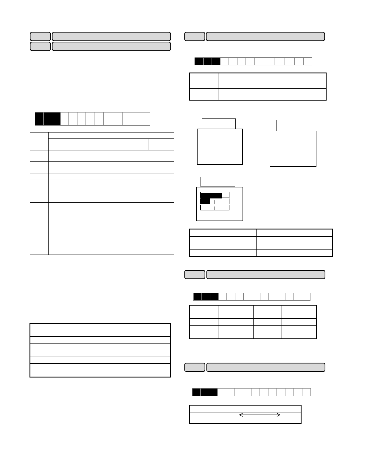
E43
E44
XThe data during inverter operation, during stopping, at
frequency setting, and at PID setting is displayed on the
LED.
XDisplay during running and stopping
During running, the items selected in "E43 LED monitor
(display selection)," are displayed. In "E44 LED monitor
(display at stopping)," specify whether to display some
items out of the set values or whether to display the
same items as during running.
E 4 3 L E D M N T R
E 4 4 L E D M N T R 2
Value
set to
E43
0
1
2
3
4
5
6
7
8
9
10
11
12
Note: For the values 10 to 12 set to E43, the data is
displayed only when selected in "H20 PID control
(operation selection)."
XDisplay at frequency setting
When a set frequency is checked or changed by the
keypad panel, the set value shown below is displayed.
Select the display item by using "E43 LED monitor
(display selection)." This display is not affected by "E44
LED monitor (display at stopping)."
Value set to
0,1,2,3,4 Set value of frequency (Hz)
10,11,12 Set value of frequency (Hz)
Note: For the values 10 to 12 set to E43, the data is
displayed only when selected in "H20 PID control
(operation selection)."
At stopping During
Set frequency value
(Hz)
Set frequency value
(Hz)
Set frequency value (Hz)
Output current (A)
Output voltage (command value) (V)
Synchronous speed
set value (r/min)
Line speed set
value (m/min.)
Load speed set
value (r/min)
Calculated torque value (%)
Output power (HP)
PID target value 1 (direct input from keypad panel)
PID target value 2 (input from "F02 Frequency 1")
PID feedback amount
E43
5 Set value of synchronous speed (r/min)
6 Set value of line speed (m/min.)
7 Set value of load speed (r/min)
8,9 Set value of frequency (Hz)
LED monitor (function)
LED monitor (display at stop mode)
E44=0 E44=1
running
Output frequency
(before slip compensation) (Hz)
Output frequency
(after slip compensation) (Hz)
Synchronous speed (r/min)
Line speed (m/min.)
Load speed (r/min)
Frequency setting
At
stopping
running
During
E45
XThis function selects the item to be displayed on the LCD
monitor in the operation mode.
E 4 5 L C D M N T R
Set value Display item
0
1
Set value: 0
During running When stopping
Set value: 1
Full-scale value of bar graph
Note: The scale cannot be adjusted.
E46
XThis function selects the language for data display on the
LCD monitor.
Note: English language is used for all LCD screens in this
manual. For other languages, refer to the relevant
instruction manual.
E47
XThis function adjusts the LCD contrast. Increase the set
value to raise contrast and decrease to lower contrast.
60.00
RUN
PRG⇒PRG MENU
⇒
LED SHIFT
F/D
60.00
Hz
A
%
Fout/Iout/TRQ
Display item Full-scale
Output frequency Maximum frequency
Output current 200% of inverter rated value
Calculated torque value 200% of motor rated value
E 4 6 LANGU A G E
Set value Language
0 Japanese 3 French
1 English 4 Spanish
2 German 5 Italian
E 4 7 CON T R A S T
Set value
Screen Low High
LCD monitor (function)
Operation status, rotating direction, operation guide
Output frequency (before slip compensation), output
current, calculated torque value in bar graph
60.00
FWD
displayed
LCD monitor (contrast)
0,1,2 • • • • • • 8,9,10
STOP
PRG⇒PRG MENU
F/D⇒LED SHIFT
Language
Set value Language
displayed
5-28
Page 78

j
)
C:Control Functions of Frequency
C01 Jump frequency 1
C02
C03 Jump frequency 3
C04 Jump frequency (Hysteresis)
Jump frequency 2
XThis function makes the set frequency jump so that the
inverter's output frequency does not match the
mechanical resonance point of the load.
XUp to three jump points can be set.
XThis function is ineffective when jump frequencies 1 to 3
are set to 0Hz.
XA jump does not occur during acceleration or deceleration.
When a jump frequency setting range overlaps another
range, both ranges are added to determine the actual
jump area.
C 0 1 J U M P H z 1
C 0 2 J U M P H z 2
C 0 3 J U M P H z 3
Setting range
G11S : 0 to 400Hz
P11S : 0 to 120Hz
In 1Hz steps (min.)
C 0 4 J U M P H Y S T R
Setting range
0 to 30Hz
In 1Hz steps (min.)
To avoid the resonance of the motor driving frequency to
the peculiar vibration frequency of the machine, the jump
frequency band can be set to the output frequency up to
three point.
XDuring accelerating, an internal set frequency is kept
constant by the lower frequency of the jump frequency
band when a set frequency enters the jump frequency
band. This means that the output frequency is kept
constant according to an internal set frequency.
When a set frequency exceeds the upper bound of the jump
frequency band, an internal set frequency reaches the value
of a set frequency. The output frequency accelerates up to
a set frequency while passing the jump frequency band
according to the acceleration time at this time.
During decelerating, it has a relation opposite to
accelerating. Refer to figure below.
XWhen two jump frequency bands or more come in
succession mutually, the lowest and highest frequency
become the lower bound and the upper bound frequency
of an actual jump frequency band respectively among
them. Refer to upper right figure.
Internal set frequency (Hz)
Jump frequency
width
Internal set frequency (Hz)
C05 Multistep frequency 1
~
C19 Multistep frequency 15
Actual
ump width
Jump frequency
width
Jump frequency 2
Jump frequency 1
Set frequency (Hz
~
XMultistep frequencies 1 to 15 can be switched by turning
on and off terminal functions SS1, SS2, SS4, and SS8.
(See E01 to E09 for terminal function definitions.)
XOFF input is assumed for any undefined terminal of SS1,
SS2, SS4, and SS8.
C 0 5 MUL T I H z - 1
C 0 6 MUL T I H z - 2
C 0 7 MUL T I H z - 3
Related functions
E01 to E09
(Set value:0 to 3
C 0 8 MUL T I H z - 4
C 0 9 MUL T I H z - 5
C 1 0 MUL T I H z - 6
C 1 1 MUL T I H z - 7
C 1 2 MUL T I H z - 8
C 1 3 MUL T I H z - 9
C 1 4 MUL T I H z 1 0
C 1 5 MUL T I H z 1 1
C 1 6 MUL T I H z 1 2
C 1 7 MUL T I H z 1 3
C 1 8 MUL T I H z 1 4
C 1 9 MUL T I H z 1 5
Setting range
G11S: 0.00 to 400.00Hz
P11S: 0.00 to 120.00Hz
In 0.01Hz steps (min.)
Output frequency
(Hz)
C10
C09
C08
C07
C06
C05
C11
C12
C13
C14
C15
C16
C17
C18
C19
)
ON
ON ON
ON
ON
5-29
FWD-P24
SS1-P24
SS2-P24
SS4-P24
SS8-P24
ON ON ON ON ON ON ON ON
ON ON ON
Jump frequency
width
width
Jump frequency 1
Jump frequency 2
Jump frequency 3
Set frequency ( Hz)
Jump frequency
Page 79

A
C20 JOG frequency
XThis function sets the frequency for jogging operation of
motor, which is different from the normal operation.
C 2 0 J O G H z
Setting range G11S : 0.00 to 400.00 Hz
P11S : 0.00 to 120.00 Hz
XStarting with the jogging frequency is combined with
jogging select signal input from the keypad panel or
control terminal. For details, see the explanations of
"E01 Terminal X1" to "E09 Terminal X9."
C21 Pattern operation (mode select)
XPattern operation is an automatic operation according to
preset operation time, direction of rotation, acceleration
and deceleration time, and frequency.
When using this function, set 10 (pattern operation) to
"F01 Frequency setting."
The following operation patterns can be selected.
C 2 1 P A T T E R N
Related functions
F01, C30
(Set value:10)
Set value
0
1
Perform a pattern operation cycle, then stop operation.
Perform pattern operation repeatedly. Stop operation
Operation pattern
using a stop command.
2
Perform a pattern operation cycle, then continue
operation with the last frequency set.
Set value:0
Forward
Output
frequency
Reverse
Set value:1
Forward
Output
frequency
Reverse
Set value:2
Forward
Output
frequency
Reverse
FWD
0
FWD
0
FWD
0
End of a cycle
Time
End of a cycle
Time
End of a cycle
Time
C22 Pattern operation (stage 1)
C28
~
Pattern operation (stage 7)
~
XSeven stages are operated in order (of function codes)
according to the values set in "C22 Pattern operation
(stage 1)" to "C28 Pattern operation (stage 7)." Each
function sets the operation time and the rotating direction
for each stage and assigns set values of the acceleration
and deceleration time.
C 2 2 STAGE 1
C 2 3 STAGE 2
C 2 4 STAGE 3
C 2 5 STAGE 4
C 2 6 STAGE 5
C 2 7 STAGE 6
C 2 8 STAGE 7
Set or
assign item
Operation time
Rotation
direction
Acceleration
and
deceleration
time
.
00 to 6000s
0
F: Forward (counterclockwise)
R: Reverse (clockwise)
1: Acceleration time 1 (F07), deceleration time 1 (F08)
2: Acceleration time 2 (E10), deceleration time 2 (E11)
3: Acceleration time 3 (E12), deceleration time 3 (E13)
4: Acceleration time 4 (E14), deceleration time 4 (E15)
Value range
Note: The operation time is represented by the three most
significant digits, hence, can be set with only three
high-order digits.
X
Setting example
100 F 3
cceleration and deceleration
time (code): 3
Motor rotating direction:
Forward (counterclockwise)
Operation time: 100s
Set the operation time to 0.00 for stages not used, which
are skipped in operation.
With regard to the set frequency value, the multistep
frequency function is assigned as listed in the table below.
Set frequencies to "C05 Multistep frequency 1," to "C11
Multistep frequency 7."
Stage No. Operation frequency to be set
Stage 1 Multistep frequency 1 (C05)
Stage 2 Multistep frequency 2 (C06)
Stage 3 Multistep frequency 3 (C07)
Stage 4 Multistep frequency 4 (C08)
Stage 5 Multistep frequency 5 (C09)
Stage 6 Multistep frequency 6 (C10)
Stage 7 Multistep frequency 7 (C11)
5-30
Page 80

XPattern operation setting example
Function
C21 (operation selection)
C22 (stage 1)
C23 (stage 2)
C24 (stage 3)
C25 (stage 4)
C26 (stage 5)
C27 (stage 6)
C28 (stage 7)
Set value
1
60.0F2
100F1
65.5R4
55.0R3
50.0F2
72.0F4
35.0F2
Operation frequency to be set
Multistep frequency 1 (C05)
Multistep frequency 2 (C06)
Multistep frequency 3 (C07)
Multistep frequency 4 (C08)
Multistep frequency 5 (C09)
Multistep frequency 6 (C10)
Multistep frequency 7 (C11)
The following diagram shows this operation.
Forward
direction
FWD
Output frequency(motor speed)
Reverse
direction
Set
value
:16
Set
value
:17
Multistep
Multistep
frequency 1
(Stage 1)
frequency 2
ACC1
ACC2
ACC4
Multistep
frequency 3
60.0S 100S 65.5S
0.1S
Output signals from terminals Y1 to Y5
Multistep
frequency 5
DEC4
Multistep
frequency 6
ACC4
ACC2
ACC3 DEC2
Multistep
frequency 4
55.0S
50.0S 72.0S
-
DEC2
Multistep
frequency 7
(Stage 7)
35.0S
0.1S
DEC1
Time
C30 Frequency command 2
XThis function selects the frequency setting method.
Related functions
E01 to E09
(Set value:11)
F01
C 3 0 F R E Q C M D 2
0 : Setting by keypad panel operation
1 : Setting by voltage input (terminal [12 ](0 to +10V))
2 : Inactive
3 : Inactive
4 : Reversible operation with polarity ( terminal [12] (-10
to +10V))
5 : Reversible operation with polarity ( terminal [12] +
[V1](Option) (-10 to +10V))
6 : Inverse mode operation (terminal [12] (+10V to 0 ))
7 : Inactive
8 : Setting by UP/DOWN control mode 1 (initial value = 0)
(terminals [UP] and [DOWN])
9 : Setting by UP/DOWN control mode 2 (initial value
=last final value) (terminals [UP] and [DOWN])
See the function explanation of E01 to E09 for
details.
10 : Setting by pattern operation
See the function explanation C21 to C28 for details.
11 : Setting by digital input or pulse train
* Optional. For details, see the instruction manual on
options.
XRunning and stopping are controlled by pressing the
STOP
and keys and by opening and closing the control
FWD
terminals.
When using the keypad panel, pressing the key
starts operation. Pressing the key pauses stage
advance. Pressing the key again restarts operation
FWD
STOP
FWD
from the stop point according to the stages. If an alarm
stop occurs, press the key to release operation
of the inverter protective function, then press the
RESET
FWD
key to restart stage advance.
If required to start operation from the first stage "C22
Pattern operation (stage 1)," enter a stop command and
press the key.
If an alarm stop occurs, press the key to release
RESET
RESET
the protective function, then press the key again.
Notes:
1. The direction of rotation cannot be reversed by a
command issued from the key on the keypad panel
REV
or terminal [REV]. Any reverse rotation commands entered
are canceled. Select forward or reverse rotation by the data
in each stage. When the control terminals are used for
operation, the self-hold function of operation command also
does not work. Select an alternate type switch when using.
2. At the end of a cycle, the motor decelerates-to-stop
according to the value set to "F08 Deceleration time 1."
5-31
Page 81

g
A
C31 Bias (terminal[12])
C32 Gain (terminal[12])
XThis function sets the Gain and Bias of the analog input
(terminals [12] ).
C 3 1 B I A S 1 2
C 3 2 G A I N 1 2
The setting range :
BIAS: -100 to +100%
GAIN:0.0 to 200%
Terminal
12
Gain Bias
Reference
volta
e
Output value of Gain 12
+10V
200%
100%
50%
XAn set value too large delays control response though
stabilizing control. A set value too small speeds up
control response but renders control unstable.
If the optimum value is not known, change the setting when
control is unstable or response is delayed.
Note:
The set value is commonly applied to terminals 12 and C1.
For input of PID feedback amount, the PID control
feedback filter (set in H25) is used.
-10 0 +10[V]
-10V
nalog input voltage
[terminal 12]
Output value of Bias 12
+10V
(+100%)
-10 0 +10[V]
Output value of Gain 12
Bias setting
-10V
(-100%)
(when negative)
Bias setting
(when positive)
C33
Analog setting signal filter
XAnalog signals input from control terminal 12 or C1 may
contain noise, which renders control unstable. This
function adjusts the time constant of the input filter to
remove the effects of noise.
C 3 3 R E F F I L T E R
Setting range: 0.00 to 5.00 seconds
5-32
Page 82

A
P01
XThis function sets the number of poles of motor 1 to be
driven. If this setting is not made, an incorrect motor
speed (synchronous speed) is displayed on the LED.
P 0 1 M 1 P O L E S
Set values: 2, 4, 6, 8, 10, 12, 14
P02 Motor 1 (capacity)
XThe nominal applied motor capacity is set at the factory.
The setting should be changed when driving a motor with
a different capacity.
P 0 2 M 1 - C A P
Set value for models with nominal applied motor of 30HP or less
: 0.01 to 60HP
Models with nominal applied motor of 40HP or more
: 0.01 to 800HP
XSet the nominal applied motor capacity listed in 9-1,
"Standard Specifications." Also set a value in the range
from two ranks lower to one rank higher than the nominal
applied motor capacity. When a value outside this
range is set, accurate control cannot be guaranteed. If
a value between two nominal applied motor capacities is
set, data for the lower capacity is automatically written
for related function data.
X When the setting of this function is changed, the values
of the following related functions are automatically set to
data of the FUJI 3-phase standard motor.
-- P03 Motor 1 (rated current)
-- P06 Motor 1 (no-load current)
-- P07 Motor 1 (% R1)
-- P08 Motor 1 (% X1)
Note:
The set values for the FUJI 3-phase standard motor are
230V, 50Hz, 4 poles for the 230V series; 460V, 50Hz, 4
poles for the 460V series.
P03 Motor 1 (rated current)
XThis function sets the rated current value of motor 1.
P 0 3 M 1 - I r
Setting range: 0.00 to 2,000A
P04 Motor 1 (Tuning)
XThis function measures and automatically writes motor
data.
P 0 4 M 1 T U N 1
Number of motor 1 poles
Motor 1 (P: Motor Parameters)
Set
value
0 Inactive
Measure the primary resistance (%R1) of the
1
motor and leakage reactance (%X) of the base
frequency when the motor is stopping and
automatically write both values in P07 and P08.
Measure the primary resistance (%R1) of the
2
motor and leakage reactance (%X) of the base
frequency when the motor is stopping,
measure the no-load current (lo) when the
motor is running, and automatically write these
values in P06, P07, and P08.
Put the motor into the state unit separating
from the machine for the tuning of the no-load
current.
In the state that the load is connected, cannot
the tuning correctly. Execute the auto tuning of
set value “1" after obtaining the test report etc.
from the motor manufactures when not making
it in the state of the motor unit, and setting P06
(no-load current) beforehand.
XPerform auto tuning when data written beforehand in
"P06 No-load current," "P07 %R1," and "P08 %X," differs
from actual motor data. Typical cases are listed below.
Auto tuning improves control and calculation accuracy.
Operation
・When a motor other than the FUJI standard 3-phase
motor is used and accurate data is required for close
control.
・When output-side impedance cannot be ignored as
when cable between the inverter and the motor is too
long or when a reactor is connected.
・ When %R1 or %X is unknown as when a non-standard
or special motor is used.
Tuning procedure
1. Adjust the voltage and frequency according to motor
characteristics. Adjust functions "F03 Maximum output
frequency," "F04 Base frequency," "F05 Rated voltage,"
and "F06 Maximum output voltage."
2. Enter untunable motor constants first. Set functions
"P02 Capacity," "P03 Rated current," and "P06 No-load
current," (input of no-load current not required when
P04=2, for running the motor at tuning, is selected).
3. When tuning the no-load current, beware of motor rotation.
4. Set 1 (motor stop) or 2 (motor rotation) to function "P04
Auto tuning." Press the key to write the set value
and press the key or key then start
tuning simultaneously.
5. Tuning takes several seconds to several tens of seconds
(when 2 is set. As the motor accelerates up to half the
base frequency according to acceleration time, is tuned
for the no-load current, and decelerates according to the
deceleration time, the total tuning time varies depending
on set acceleration and deceleration times.)
6. Press the key after the tuning is completed .
7. End of procedure.
STOP
FWD REV
FUNC
DAT
5-33
Page 83
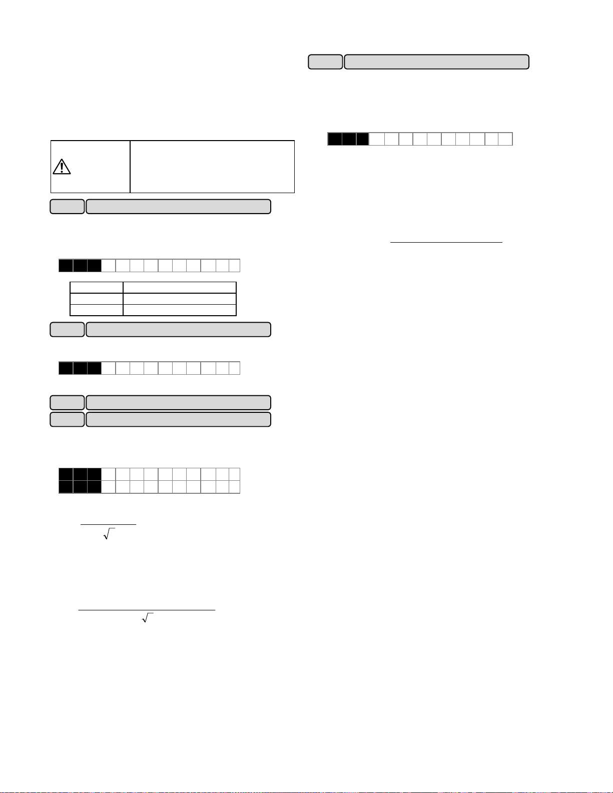
(
)
Note1:
If REMOTE operation(F02: 1) is selected, operation signal is
given from terminal [FWD] or [REV].
Note2:
Use function "A13 Motor 2 (auto tuning)," to tune motor 2. In
this case, set values described in 1 and 2 above are for the
function (A01 - ) of motor 2.
WARNING
P05 Motor 1 (On-line Tuning)
XLong-time operation affects motor temperature and motor
speed. Online tuning minimizes speed changes when
motor temperature changes.
XAuto tuning(P04/A13: 2) should be done to use this function.
P 0 5 M 1 T U N 2
Set value Operation
0 Inactive
1 Active
P06 Motor 1 (no-load current)
XThis function sets the no-load current (exciting current) of
motor 1.
P 0 6 M 1 - I O
Setting range: 0.00 to 2,000A
When the auto tuning value is set to 2,
the motor rotates at a maximum of half
the base frequency. Beware of motor
rotation.
as injury may result.
P07 Motor 1 (%R1 setting)
P08 Motor 1 (%X setting)
XWrite this data when using a motor other than the FUJI
standard 3-phase motor and when the motor constant and
the impedance between the inverter and motor are known.
P09 Slip compensation control
XChanges in load torque affect motor slippage, thus causing
variations in motor speed. The slip compensation control
adds a frequency (proportional to motor torque) to the
inverter output frequency to minimize variations in motor
speed due to torque changes.
P 0 9 SL I P C O M P1
XAuto tuning(P04/A13: 2) should be done to use this
function.
Set value: 0.00 to 15.00Hz
XCalculate the amount of slip compensation using the
following formula:
amount ioncompenssat Slip
Slippage = Synchronous speed - Rated speed
×frequency =Base
/min]Slippage[r
n]speed[r/mi sSynchronou
[Hz]
P 0 7 M 1 - % R 1
P 0 8 M 1 - % X
XCalculate %R1 using the following formula:
R R1+Cable
%R1=
()
・I3V/
R1 : Primary coil resistance value of the motor [Ω]
Cable R : Output-side cable resistance value [Ω]
V : Rated voltage [V] I: Motor rated current [A]
XCalculate %X using the following formula:
%X =
X1 : Primary leakage reactance of the motor [Ω]
X2 : Secondary leakage reactance (converted to a
primary value)of the motor [Ω]
XM : Exciting reactance of the motor [Ω]
Cable X : Output-side cable reactance [Ω]
V : Rated voltage [V] I : Motor rated current[A]
Note:
For reactance, use a value in the data written in "F04
Base frequency 1."
XWhen connecting a reactor or filter to the output circuit, add its
value. Use value 0 for cable values that can be ignored.
100[%]×
()
・I3V/
X Cable+X2+XMX1+X2・XM/
100[%]×
5-34
Page 84

A
∧
H03 Data initializing
High Performance functions (H:High Performance function)
XThis function returns all function data changed by the
customer to the factory setting data. (initialization).
H 0 3 D A T A I N I T
Set value 0: Disabled.
1: Initializing data.
XTo perform initialization, press the and keys
together to set 1, then press the key. The set
STOP
FUNC
DAT
values of all functions are initialized. The set value in
H03 automatically returns to 0 following the end of
initialization.
H04 Auto-reset(Times)
H05 Auto-reset (Reset interval)
XWhen the inverter protective function which invokes the
retry operation is activated, this function releases
operation of the protective function and restarts
operation without issuing an alarm or terminating output.
H 0 4 A U T O - R E S E T
H 0 5 R E S E T I N T
Set the protective function release count and waiting
time from its operation startup to release.
Setting range (Count) : 0, 1 to 10
(Waiting time) : 2 to 20 seconds
To not use the retry function, set 0 to "H04 Retry (count)."
XInverter protective functions that can invoke retry
function.
OC1,OC2,OC3
: Overcurrent
OV1,OV2,OV3
: Overvoltage
OH1
: Heat sink overheating
OH3
: Inverter inside overheating
dBH
: Braking resistor overheating
OL1
: Motor 1 overload
OL2
: Motor 2 overload
OLU
: Inverter overload
XWhen the value of "H04 Retry (count)," is set from 1 to
10, an inverter run command is immediately entered
following the wait time set in H05, "Retry (wait time),"
and the startup of the retry operation. If the cause of
the alarm has been removed at this time, the inverter
starts without switching to alarm mode. If the cause of
the alarm still remains, the protective function is
reactivated according to the wait time set in "H05 Retry
(waiting time)." This operation is repeated until the
cause of the alarm is removed. The restart operation
switches to alarm mode when the retry count exceeds
the value set in "H04 Retry (count)."
The operation of the retry function can be monitored
from terminals Y1 to Y5.
When the retry function is selected,
operation automatically restarts depending
WARNING
on the cause of the trip stop. (The
machine should be designed to ensure
safety during a restart)
as accident may result.
When retry succeeded
Occurrence
Alarm
Auto matic
release
command
of
protective
function
Output
frequency
Output
signals
terminals
Y1 to Y5
Extinction
0.1S
Waiting time
(H05)
Restart
5min . after
constant speed
ON
retry failed
Occurrence
Alarm
Auto matic
release
command
of
protective
function
Output
frequency
Output
signals
terminals
Y1 to Y5
H06 Fan stop operation
0.1S
H05:
Wait
time
First Second
0.1S
H05:
Wait
time
ON
Extinction
0.1S
XThis function specifies whether cooling fan ON/OFF
control is automatic. While power is applied to the
inverter, the automatic fan control detects the
temperature of the cooling fan in the inverter and turns
the fan on or off.
When this control is not selected, the cooling fan rotates
continually.
H 0 6 FAN S T O P
Set value 0: ON/OFF control disabled.
1: ON/OFF control enabled.
The cooling fan operating status can be monitored from
terminals Y1 to Y5.
Time
RESET the times
of auto-reset
Alarm
reset
Retry
end
Count set in
H04 (count)
5-35
Page 85

q
y
H07
ACC/DEC (Mode select) pattern
XThis function selects the acceleration and deceleration
pattern.
H 0 7 A C C P T N
Set value
0: Inactive (linear acceleration and deceleration)
1: S-shape acceleration and deceleration (mild)
2: S-shape acceleration and deceleration (*)
3: Curvilinear acceleration and deceleration
Related functions
U02 to U05
* The S-shape range is set by the
function: U02 to U05 when the set value "2" is selected.
The detail is referred to the function: U02 to U05.
[S-shape acceleration and deceleration]
This pattern reduces shock by mitigating output frequency
changes at the beginning/end of acceleration and
deceleration.
Output frequency
f[Hz]
α
α
0
Mild S-shape ern
Arbitrary S-shape
t[s]
βacc βacc
βdec
βdec
<Pattern constants>
When 1 is selected in H07
Range of
S-shape(
Time for
S-shape at
acceleration
(
β
acc)
Time for
S-shape at
deceleration
(
β
dec)
(mild S-shape pattern)
0.05 x max. output freq. (Hz)
α
)
0.10 x acceleration time (s)
0.10 x deceleration time (s)
When 2 is selected in H07
(arbitrary S-shape pattern)
(U02 to U05) x max. output
freq. (Hz)
(U02, U03) x2 x
acceleration time (s)
U04, U05 x2 x
deceleration time (s)
∗ When acceleration and deceleration times are very
long or short, acceleration and deceleration are
rendered linear.
It may be switched the acceleration and deceleration
time during constant speed or stopping by the function
"acceleration and deceleration time selection"(E01 to
E09: 4, 5).
The signal may be ignored switched during S-shape at
acceleration.
The linear deceleration time is corresponded if switched
during S-shape at deceleration.
It may be switched to the S-shape operation if output
frequency is reached to the setting frequency or change
to acceleration control.
[ Curvilinear acceleration and deceleration ]
This function is used to minimize motor acceleration and
deceleration times in the range that includes a
constant-output range.
Output
frequency
Maximum
output
uenc
fre
Set
frequency
Base
frequency
Acceleration time
0
Deceleration time
t[sec]
H08
XWhen accidental reversing is expected to cause a
malfunction, this function can be set to prevent reversal.
H 0 8 R E V L O C K
Set value 0: Inactive
When reversible operation with polarity(set value: "4" or
"5") is selected in frequency command: F01, C30, the
inverter operates as follows.
Operation
command
Short FWD-CM
terminals or
FWD
: ON
Short REV-CM
terminals or
REV
: ON
This function prevents a reversing operation resulting from
a connection between the REV and P24 terminals,
inadvertent activation of the key, or negative analog
input from terminal 12 or V1. During this function is
operating, "0.00Hz" is displayed on the LED monitor.
This function cannot be prevented against H18: Torque
control function. It may be reverse because of the torque
signal and load.
Rev. phase sequence lock
1: Active
0V to 10V input -10V to 0V input
The inverter operates. The frequency display
is "0.00" Hz.
The frequency display
The inverter operates.
is "0.00" Hz.
REV
5-36
Page 86

H09 Start mode
This function smoothly starts the motor which is coasting
after a momentary power failure or after the motor has
been subject to external force, without stopping motor.
At startup, this function detects the motor speed and
outputs the corresponding frequency, thereby enabling a
shock-free motor startup. Although the normal startup
method is used, when the coasting speed of the motor is
120 Hz or more as an inverter frequency, when the value
set to "F03 Maximum frequency," exceeds the value set to
"F15 Frequency limiter (upper limit)." and when the
coasting speed is less than 5 Hz as an inverter frequency.
H 0 9 S T A R T M O D E
Set value 0,1,2
Set value STM
Restart after a
momentary power
Other
operation
failure or
Line-to-inverter
switching
0
OFF /
not selected
1
Inactive
(normal starting)
Active
Inactive
(smoothly starting)
2
Active
any value ON Active
STM: Start characteristics selection signal(E01 to E09: 26)
NOTE:
-1: Automatically restart when overcurrent or overvoltage is
detected during smoothly starts.
-2: The coasting speed is used 100 Hz or less as an
inverter frequency.
-3: When H09:2 or STM:ON, it needs the time more than
normal start even the motor is STOP because the motor
speed is detected on ALL situation. And it may be
rotated the motor when the load is too small.
-4: Auto tuning(P04/A13: 2) should be done to use this
function.
-5: When the used motor slippage is too differ from FUJI
motor, the "Slip compensation control (P09, A18)"
should be set. The characteristics may not be satisfied.
XWhen the operation above is to be problem, this function
is not used (inactive).
XThis function may not be satisfied the characteristics
because of the load condition, motor constant, operating
frequency, coasting speed, wire length, momentary
power failure time or external factor.
P24
STM
FWD
Output
frequency
(motor speed)
0.1 s or
longer
Speed
search
0.2 s or
longer
ON
ON
Acceleration
In this section, the output
voltage is gradually increased
in steps to minimize shock.
Time
Time
Note: The dotted-dashed line indicates motor speed.
H10 Energy-saving operation
XWhen the output frequency is fixed (constant-speed
operation) at light loads and except for”0.0” is set to F09,
"Torque boost 1," this function automatically reduces the
output voltage, while minimizing the product (power) of
voltage and current.
XAuto tuning(P04/A13: 2) should be done to use this
function.
XThe energy-saving operation does not be operated when
set below.
- Under Torque control
- Selected the Automatic torque boost
- Selected the Torque vector control
- Under PG vector control
H 1 0 ENER G Y SAV
Set value 0: Inactive
1: Active
Note:
-Use this function for square law reduction torque loads
(e.g., fans, pumps). When used for a constant-torque
load or rapidly changing load, this function causes a delay
in control response.
-The energy-saving operation automatically stops
during acceleration and deceleration and when the
torque limiting function is activated.
H11 DEC mode
XThis function selects the inverter stopping method when a
stop command is entered.
H 1 1 DEC M O D E
Set value 0: Deceleration-to-stop based on data set to "H07
Non-linear acceleration and deceleration"
1: Coasting-to-stop
Note:
This function is effective only when a stop command is
entered and, therefore, is ineffective when the motor is
stopped by lowering the set frequency.
H12 Instantaneous overcurrent limiting
XAn overcurrent trip generally occurs when current flows
above the inverter protective level following a rapid
change in motor load. The instantaneous overcurrent
limiting function controls inverter output and prohibits the
flow of a current exceeding the protective level even
when the load changes.
XAs the operation level of the instantaneous overcurrent
limiting function cannot be adjusted, the torque limiting
function must be used.
As motor generation torque may be
reduced when instantaneous
overcurrent limiting is applied, set this
function to be inactive for equipment
such as elevators, which are
WARNING
adversely affected by reduced motor
generation torque, in which case an
overcurrent trip occurs when the
current flow exceeds the inverter
protective level. A mechanical brake
should be used to ensure safety.
as accident may result.
H 1 2 INST C L
Set value 0: Inactive
1: Active
5-37
Page 87
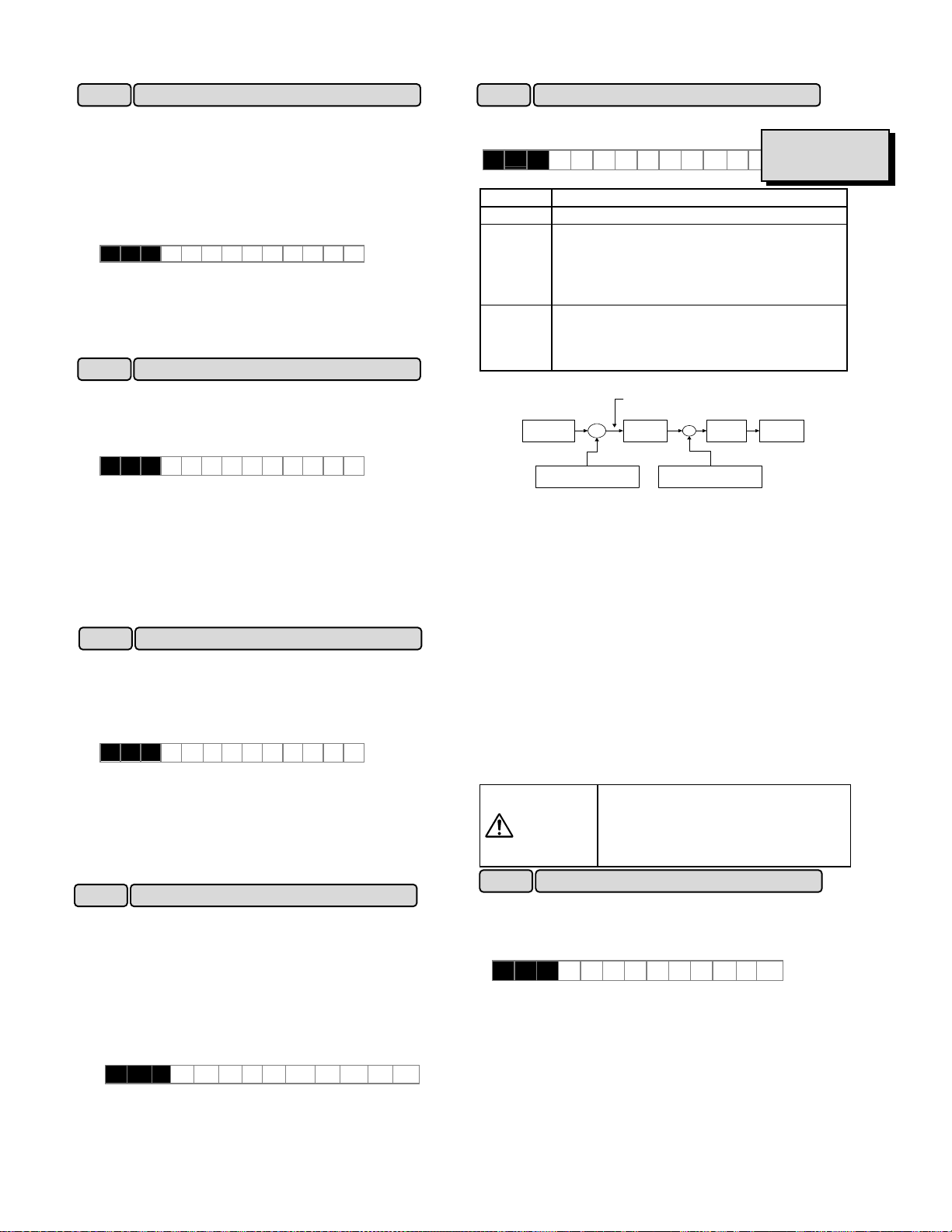
H13 Auto-restart (Restart time)
XInstantaneous switching to another power line (when the
power of an operating motor is cut off or power failure
occurs) creates a large phase difference between the
line voltage and the voltage remaining in the motor,
which may cause electrical or mechanical failure. To
rapidly switch power lines, write the remaining voltage
attenuation time to wait for the voltage remaining in the
motor to attenuate. This function operates at restart
after a momentary power failure.
H 1 3 R E S T A R T T
Setting range: 0.1 to 5.0 seconds
XWhen the momentary power failure time is shorter than
the wait time value, a restart occurs following the wait
time. When the power failure time is longer than the
wait time value, a restart occurs when the inverter is
ready to operate (after about 0.2 to 0.5 second).
H14
Auto-restart (Freq. fall rate)
XThis function determines the reduction rate of the output
frequency for synchronizing the inverter output
frequency and the motor speed. This function is also
used to reduce the frequency and thereby prevent
stalling under a heavy load during normal operation.
H 1 4 F A L L R A T E
Setting range: 0.00, 0.01 to 100.00 Hz/s
XWhen 0.00 is set, the frequency is reduced according to
the set deceleration time.
Note:
A too large frequency reduction rate is may temporarily
increase the regeneration energy from the load and
invoke the overvoltage protective function. Conversely,
a rate that is too small extends the operation time of the
current limiting function and may invoke the inverter
overload protective function.
H15 Auto-restart (Holding DC voltage)
XThis function is for when 2 (deceleration-to-stop at power
failure) or 3 (operation continuation) is set to "F14
Restart after momentary power failure (operation
selection)." Either function starts a control operation if
the main circuit DC voltage drops below the set
operation continuation level.
H 1 5 H O L D V
Setting range 230 V series: 200 to 300V
460 V series: 400 to 600V
XWhen power supply voltage to the inverter is high, control
can be stabilized even under an excessive load by
raising the operation continuation level. However, when
the level is too high, this function activates during normal
operation and causes unexpected motion. Please
contact Fuji electric when changing the initial value.
H16
Auto-restart (OPR command selfhold time)
XAs the power to an external operation circuit (relay
sequence) and the main power to the inverter is
generally cut off at a power failure, the operation
command issued to the inverter is also cut off. This
function sets the time an operation command is to be
held in the inverter. If a power failure lasts beyond the
self-hold time, power-off is assumed, automatic restart
mode is released, and the inverter starts operation at
normal mode when power is applied again. (This time
can be considered the allowable power failure time.)
H 1 6 S E L F H O L D T
Setting range: 0.0 to 30.0 seconds, 999
When "999" is set, an operation command is held (i.e.,
considered a momentary power failure) while control power
in the inverter is being established or until the main circuit
DC voltage is about 100Vdc.
H18 Torque control
XThis function controls motor torque according to a
command value.
H 1 8
Set value
T R Q C T R L
Operation
Related functions
E01toE09
(Set value: 23)
0 Inactive (Operation by frequency command)
1 Torque control active
0 to +10V analog voltage input to terminal 12
and the direction of rotation (FWD or REV) is
used for the torque command value. 0 is
used for 0 to -10V.
2 Torque control active
-10 to +10V analog voltage input to terminal
12 and the direction of rotation (FWD or
REV) is used for the torque command value.
Torque control block diagram
Torque command value
Voltage at
terminal 12
Forward com mand
Reverse comm and
x
Torque
lim itation
+
Regulator
-
De te cte d torq ue
current
Output
frequency
The torque command value is +200% when the voltage at
terminal 12 is +10V and is -200% when the voltage is -10V.
XAuto tuning(P04/A13: 2) should be done to use this
function.
XIn torque control, the torque command value and motor
load determine the speed and direction of rotation.
XWhen the torque is controlled, the upper limit of
frequency refers to the minimum value among the
maximum frequency , the frequency limiter (upper limiter)
value, and 120 Hz. Maintain the frequency at least
one-tenth of the base frequency because torque control
performance deteriorates at lower frequencies.
XIf the operation command goes off during a torque control
operation, the operation is switched to speed control and
the motor decelerates-to-stop. At this time, the torque
control function does not operate.
XThis function cannot be used when the motor 2 is
selected.
XThis function cannot be used for FRN-P11S.
The malfunction may be occurred
when the set torque is mistaken. (up
WARNING
to upper frequency, maximum
frequency or 120Hz)
as accident may result.
H19 Active drive
XThis function automatically extends accelerating time
against acceleration operation of 60 seconds or longer to
prevent an inverter trip resulting from a temperature rise
in inverter due to overcurrent.
H 1 9 AU T RE D
Set value 0: Inactive
1: Active
(When the active drive function is activated, the
acceleration time is three times the selected time.)
5-38
Page 88
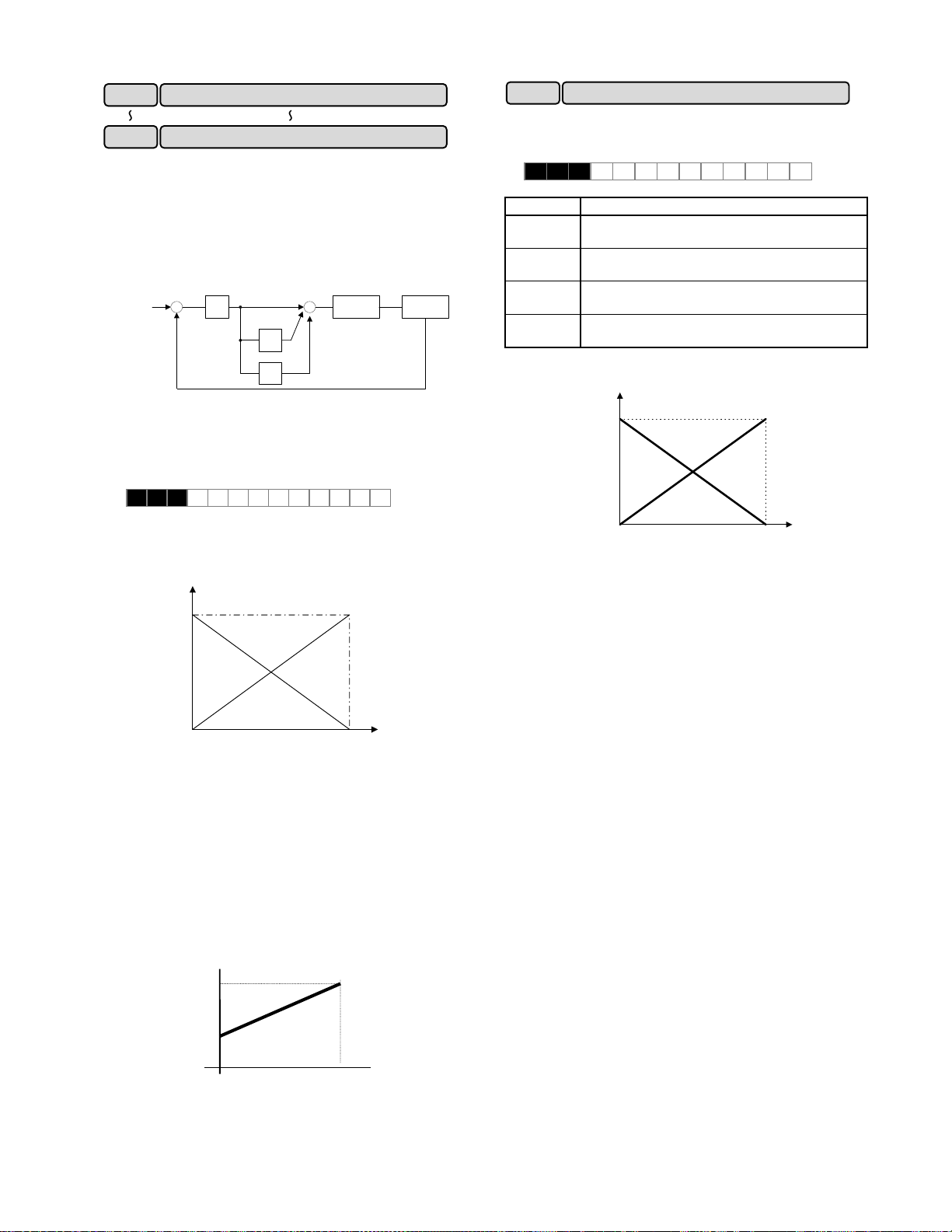
H20 PID control (Mode select)
~
H25 PID control(Feedback filter)
~
XPID control detects the amount of control (feedback
amount) from a sensor of the control target, then
compares it with the target value (e.g., reference
temperature). If the values differ, this function performs a
control to eliminate the deviation. In other words, this
control matches the feedback amount with the target
value.
This function can be used for flow control, pressure control,
temperature control, and other process controls.
Target
value
+
-
P
Feedback amount
+
++
I
D
Drive
section
Control
target
XForward or reverse operations can be selected for PID
controller output. This enables motor revolutions to be
faster or lower according to PID controller output
XThis function cannot be used when the motor 2 is
selected.
H 2 0 P I D M O D E
Set value 0: No operation
1: Forward operation
2: Reverse operation
Inverter output
frequency
Maximum
frequency
d
r
a
n
w
r
io
o
t
a
F
r
e
p
o
R
e
v
o
e
p
r
e
s
e
r
a
t
i
o
n
0
0% 100%
PID output
XThe target value can be entered using F01, "Frequency
setting 1," or directly from the keypad panel. Select any
terminal of Terminals X1 (E01) to X9 (E09) and set value
11 (frequency setting switching).
For entry from F01, "Frequency setting 1," input an OFF
signal to the selected terminal. For direct entry from the
keypad panel, turn on the selected terminal.
XFor the target value and feedback amount, the process
amount can be displayed according to the values set in
E40, "Display coefficient A," and E41, "Display
coefficient B."
Display
Display coefficient A
H21 PID control (Feedback signal)
This function selects the feedback amount input terminal
and electrical specifications of the terminal. Select a value
from the table below according to sensor specifications.
H 2 1 FB S I G N A L
Set value Descriptions
0 Control terminal 12, forward operation (0 to
10V voltage input)
1 Control terminal C1, forward operation (4 to
20mA current input)
2 Control terminal 12, reverse operation (10
to 0V voltage input)
3 Control terminal C1, reverse operation (20
to 4mA current input)
Feedback amount
100%
w
r
o
F
0%
0V
4mA
Input
n
o
i
t
a
r
e
p
o
d
r
a
R
e
v
o
e
p
r
e
s
r
e
a
t
i
o
n
10V
20mA
Only positive values can be input for this feedback amount
of PID control. Negative values (e.g., 0 to -10V, -10 to 0V)
cannot be input, thereby the function cannot be used for a
reverse operation by an analog signal.
Display coefficient B
0% 100%
Target value or
feedback amount
5-39
Page 89

H22 PID control (P-gain)
H23 PID control (I-gain)
H24 PID control (D-gain)
XThese functions are not generally used alone but are
combined like P control, PI control, PD control, and PID
control.
XP operation
Operation using an operation amount (output frequency)
proportional to deviation is called P operation, which
outputs an operation amount proportional to deviation,
though it cannot eliminate deviation alone.
Deviation
Time
Operation
amount
H 2 2 P - G A I N
Setting range: 0.01 to 10.0 times
P (gain) is the parameter that determines the response
level for the deviation of P operation. Although an
increase in gain speeds up response, an excessive gain
causes vibration, and a decrease in gain delays response.
The value "1" is the P(gain) that is when the maximum
frequency 100% at deviation 100%.
Response
Time
X I operation
An operation where the change speed of the operation
amount (output frequency) is proportional to the deviation is
called an I operation. An I operation outputs an operation
amount as the integral of deviation and, therefore, has the
effect of matching the control amount (feedback amount) to
the target value (e.g., set frequency), though it deteriorates
response for significant changes in deviation.
Deviation
Time
amount
Operation
H 2 3 I - G A I N
Setting range: 0.0 (Inactive), 0.1 to 3600 seconds
"H23 I-gain" is used as a parameter to determine the effect
of I operation. A longer integration time delays response
and weakens resistance to external elements. A shorter
integration time speeds up response, but an integration
time that is too short causes vibration.
XD operation
An operation where the operation amount (output
frequency) is proportional to the deviation differential is
called a D operation, which outputs an operation amount
as the deviation differential and, therefore, is capable of
responding to sudden changes.
Deviation
Time
amount
Operation
H 2 4 D-GAI N
Setting range: 0.00 (Inactive), 0.01 to 10.0 seconds
"H24 D-gain" is used as a parameter to determine the
effect of a D operation. A longer differentiation time
causes vibration by P operation quickly attenuating at the
occurrence of deviation. Excessive differentiation time
could cause vibration. Shortening the differentiation
time reduces attenuation at the occurrence of deviation.
XPI control
P operation alone does not remove deviation completely.
P + I control (where I operation is added to P operation)
is normally used to remove the remaining deviation. PI
control always operates to eliminate deviation even when
the target value is changed or there is a constant
disturbance. When I operation is strengthened,
however, the response for rapidly changing deviation
deteriorates. P operation can also be used individually
for loads containing an integral element.
X PD control
If deviation occurs under PD control, an operation
amount larger than that of D operation alone occurs
rapidly and prevents deviation from expanding. For a
small deviation, P operation is restricted. When the
load contains an integral element, P operation alone may
allow responses to vibrate due to the effect of the
integral element, in which case PD control is used to
attenuate the vibration of P operation and stabilize
responses. In other words, this control is applied to
loads in processes without a braking function.
XPID control
PID control combines the P operation, the I operation
which removes deviation, and the D operation which
suppresses vibration. This control achieves
deviation-free, accurate, and stable responses.
XAdjusting PID set value
Adjust the PID value while monitoring the response
waveform on an oscilloscope or other instrument if
possible. Proceed as follows:
-Increase the value of "H22 P-gain" without generating
vibration.
- Decrease the value of "H23 I-gain" without generating
vibration.
- Increase the value of "H24 D-gain" without generating
vibration.
5-40
Page 90

+
-To suppress vibration with a frequency roughly equivalent
to the value "H24 D-gain," decrease the value of H24. If
there is residual vibration with 0.0, decrease the value of
"H22 P-gain."
Before
adjustment
Internal resistance of
PTC thermistor
Rp2
After
Response
adjustment
Time
H25 PID control (Feedback filter)
XThis filter is for feedback signal input from terminal [12] or
[C1]. This filter stabilizes operation of the PID control
system. A set value that is too large, however,
deteriorates response.
H 2 5 F B F I L T E R
Setting range: 0.0 to 60.0 seconds
H26 PTC thermistor (Mode select)
XSet this function active when the motor has a PTC
thermistor for overheat protection
H 2 6 P T C M O D E
Set value 0: Inactive
1: Active
XConnect the PTC thermistor as shown in the figure
below.
Turn on switch “PTC” on the control PCB.
The trip mode is activated by “OH2:External thermal
relay tripped.”
PTC
thermistor
13
C1
Resistor
250 Ohom
PTC
ON OFF
1k Ohom
H27
(Level)
DC10V
OH2
Comparator
11
0V
H27 PTC thermistor (Level)
XThe voltage input to terminal [C1] is compared to the set
voltage (Level). When the input voltage is equal to or
greater than the set voltage (Level), "H26 PTC thermistor
(Mode select)," starts.
H 2 7 P T C L E V E L
Setting range: 0.00 to 5.00V
XThe PTC thermistor has its own alarm temperature. The
internal resistance value of the thermistor largely change
at the alarm temperature. The operation (voltage) level
is set using this change in the resistance value.
Rp1
Alarm
temperature
Temperature
The figure in "H26 PTC thermistor (Mode select)," shows
that resistor 250Ω and the thermistor (resistance value
Rp) are connected in parallel. Hence, voltage Vc
(Level) at terminal [C1] can be calculated by using the
following formula.
Rp250
・
Rp250
Vc
=
1
1000
+
+
・
×
Rp250
Rp250
+
][
V10
The operation level can be set by bringing Rp in the Vc
calculation formula into the following range.
Rp
< Rp < Rp2
1
To obtain Rp easily, use the following formula.
RpRp
21
Rp
=
H28 Droop operation
2
[Ω]
When two or more motors drive a single machine, a higher
load is placed on the motor rotating the fastest. Droop
operation achieves a good load balance by applying
drooping characteristics to speed against load variations.
Auto tuning(P04: 2) should be done to use this function.
This function cannot be used when the motor 2 is selected.
The drooping speed at constant torque is set.
H 2 8 DROO P
Set value
: -9.9Hz to 0.0Hz
Characteristics of the motor
When droop operation
Freq.
setting
value
Rated torque
Rated torque
is acti ve
Torque
(drive)
0 Speed
(brake)
Acc/Dec calculation
+
+
H28
Droop freq.
+
Feedback amount
◆This function cannot be used for FRN-P11S.
Setting value of |H28|
When droop operation
is inactive
Freq. setting
Output
+
P09
freq.
Slip compensa tion freq.
Setting value of |H28|
Torque calculation
τ
+ : drive
- : brake
1
1
5-41
Page 91

H30 Serial link (Function select)
XThe link function (communication function) provides
RS-485 (provided as standard) and bus connections
(optional).
The serial link function includes:
1) Monitoring (data monitoring, function data check)
2) Frequency setting
3) Operation command
(FWD, REV, and other commands for digital input)
4)Write function data
H 3 0 L I N K F U N C
Setting range: 0 to 3
Communication can be enabled and disabled by a digital
input. This function sets the serial link function when
communication is enabled.
Set value Frequency
0 Disabled Disabled
1 Enabled Disabled
2 Disabled Enabled
3 Enabled Enabled
The data monitoring and function data write functions are
always enabled. Disabling communication using digital
input brings about the same result as when "0" is set to this
function. When the bus option is installed, this setting
selects the function of the option and the RS-485 interface
is restricted to monitoring and writing function data.
H31 RS-485 (Address)
~
H39 RS-485 (Response interval)
These functions set the conditions of RS-485 Modbus-RTU
communication. Set the conditions according to the
upstream device. Refer to technical manual for the protocol.
XThis function sets the station address of RTU.
H 3 1 4 8 5 A D R E S S
Setting range: 1 to 247
XThis function sets processing at communication error and
sets the error processing timer value.
H 3 2 M O D E O N E R
Setting range: 0 to 3
Set value Processing at communication error
0 Immediate Er 8 trip (forced stop)
1
2
3 Continue operation.
H 3 3 T I M E R
Setting range: 0.0 to 60.0 seconds
XThis function sets the baud rate.
H 3 4 B A U D R A T E
Setting range: 0 to 3
Set value Baud rate
0 19200 bit/s
1 9600 bit/s
2 4800 bit/s
3 2400 bit/s
command
~
Continue operation within timer time, Er8 trip
after timer time.
Continue operation and effect retry within timer
time, then invoke an Er8 trip if a
communication error occurs. If an error does
not occur, continue operation.
Operation
command
XThis function sets data length.
H 3 5 LENGTH
Setting range: 0
Set value Data length
0 8 bit
XThis function sets the parity bit.
H 3 6 PARITY
Setting range: 0 to 2
Set value Parity bit
0 None
1 Even
2 Odd
XThis function sets the stop bit.
H 3 7 STOP B I T S
Setting range: 0, 1
Set value Stop bit
0 2 bit
1 1 bit
The stop bit is automatically configured by the value of the
parity bit. For parity “NONE” the stop bit is 2bits. For
parity “EVEN” or “ODD” the stop bit is 1 bit.
XIn a system where the local station is always accessed
within a specific time, this function detects that access
was stopped due to an open-circuit or other fault and
invokes an Er 8 trip.
H 3 8 NO RES t
Setting range: 0 (No detection)
1 to 60 seconds
XThis function sets the time from when a request is issued
from the upstream device to when a response is
returned.
H 3 9 INTERV A L
Setting range: 0.00 to 1.00 second
5-42
Page 92

A01 Maximum frequency2
XThis function sets the maximum frequency for motor 2
output by the inverter. This function operates the same
as "F03 Maximum frequency 1." For details, see the
explanation for F03.
A 0 1 M A X H z - 2
A02
XThis function sets the maximum output frequency in the
constant-torque area of motor 2 (i.e., output frequency at
rated output voltage). This function operates the same
as "F04 Base frequency 1." For details, see the
explanation for F04.
A 0 2 B A S E H z - 2
A03
XThis function sets the rated value of voltage output to
motor 2. This function operates the same as "F05
Rated voltage 1." For details, see the explanation for
F05.
A 0 3 R A T E D V 2
A04
XThis function sets the maximum value of the inverter
output voltage of motor 2. This function operates the
same as "F06 Maximum voltage 1." For details, see the
explanation for F06.
A 0 4 M A X V - 2
A05
XThis function sets the torque boost function of motor 2.
This function operates the same as "F09 Torque boost
1." For details, see the explanation for F09.
A 0 5 T R Q B O O S T 2
A06 Electronic thermal overload relay 2 (Select)
A07 Electronic thermal overload relay 2 (Level)
A08
XThis function sets the function of the electronic thermal
overload relay for motor 2. This function operates the
same as F10 to F12, "Electronic thermal overload relay
1." For details, see the explanations for F10 to F12.
A 0 6 E L C T R N O L 2
A 0 7 O L L E V E L 2
A 0 8 T I M E C N S T 2
A09 Torque vector control 2
XThis function sets the torque vector function of motor 2.
This function operates the same as "F42 Torque vector
control 1." For details, see the explanation for F42.
A 0 9 T R Q V E C T O R 2
A10 Number of motor-2 poles
XThis function sets the number of poles of motor 2 to be
driven. This function operates the same as "P01 Number
of motor-1 poles." For details, see the explanation for P01.
A 1 0 M 2 P O L E S
Electronic thermal overload relay 2 (Thermal time constant)
Base frequency 2
Rated voltage 2
Maximum voltage 2
Torque boost 2
Motor 2 (A:Altemative Motor Parameters)
A11 Motor 2 (Capacity)
XThis function sets the capacity of motor 2. This function
operates the same as "P02 Motor 1 (Capacity)." For
details, see the explanation for P02. However, the
related motor data functions change to "A12 Motor 2
(Rated current)," "A15 Motor 2 (No-load current)," "A16
Motor 2 (%R1 setting)," and "A17 Motor 2 (%X setting)."
A 1 1 M2 - CA P
A12 Motor 2 (Rated current)
XThis function sets the rated current of motor 2. This
function operates the same as "P03 Motor 1 (Rated
current)." For details, see the explanation for P03.
A 1 2 M2 - I r
A13 Motor 2 (Tuning)
XThis function sets the auto tuning of motor 2. This
function operates the same as "P04 Motor 1 (Tuning)."
For details, see the explanation for P04.
A 1 3 M2 T U N 1
A14 Motor 2 (On-line tuning)
XThis function sets the online tuning of motor 2. This
function operates the same as "P05 Motor 1 (On-line
tuning)." For details, see the explanation for P05.
A 1 4 M2 T U N 2
A15 Motor 2 (No-load current)
XThis function sets the no-load current of motor 2. This
function operates the same as "P06 Motor 1 (No-load
current)." For details, see the explanation for P06.
A 1 5 M2 - I o
A16 Motor 2 (%R1 setting)
A17 Motor 2 (%X setting)
XThis function sets %R1 and %X of motor 2. This
function operates the same as "P07 Motor 1 (%R1
setting)," and "P08 Motor 1 (%X setting)." For details,
see the explanations for P07 and P08.
A 1 6 M2 - % R 1
A 1 7 M2 - % X
A18 Slip compensation control 2
XThis function sets the amount of slip compensation for
motor 2. This function operates the same as "P09 Slip
compensation control." For details, see the explanation
for P09.
A 1 8 SL IP C O M P2
Set value : 0.00Hz to 15.00Hz
XCalculate the amount of slip compensation using the
following formula:
Slip compenssation amount
frequency Base ×=
min]/r[ Slippage
][Hz
min]/r[ speed sSynchronou
Slippage = Synchronous speed-Rated speed
5-43
Page 93

0
−
U01
XThis function becomes effective, when the torque limit
(brake) is used. The inverter controls to increase the
output frequency so that torque calculations do not
exceed the torque limit (brake) setting ( F41 or E17).
(When F41 or E17 is set to 999, it becomes invalid.)
This function sets the increment of upper limit for
output frequency.
When the regeneration avoidance is selected, the
resurrection ability can be improved by raising the
increment of upper limit. However, the output
frequency of the inverter is limited at the frequency
limit(high): F15.
Setting range : 0 to 65535
The set value "15" becomes 1Hz.
(The set value "1" becomes 1/15Hz)
XWhen "2" is set in the function code: H07, both
curvilinear acceleration and deceleration ranges of
S-shape can be set up arbitrarily.
The range is the ratio for maximum output frequency 1
(F03) or 2 (A01) .
U 0 2 U S E R 0 2
U 0 3 U S E R 0 3
U 0 4 U S E R 0 4
U 0 5 U S E R 0 5
Setting range : 1 to 50%
Output frequency
X100% value of this function means maximum frequency
(fmax) .
Acceleration time “tacc” and deceleration time “tdec”
of upper figure become longer than the linear
acceleration time and deceleration time. When the set
acceleration time(F07,E10,E12,E14) is assumed to
be “Ta” and deceleration time(F08,E11,E13,E15) is
assumed to be “Td”, “tacc” and “tdec” can be
calculated by the following expressions.
Maximum c ompensation frequency during braking torque limit
U 0 1 U S E R 0 1
1st S-shape level at acceleration (start)U02
2nd S-shape level at acceleration (stop)U03
1st S-shape level at deceleration (start)U04
2nd S-shape level at deceleration (stop)U05
f[Hz]
f1
U03
U02
f0
tacc
U04
tdec
U : User function
U05
t[s]
- At acceleration,
03U02U
×≥−
×≥−
100
100
×<−
+
100
+
100
+
+
S-shape clause
maxf|0f1f|
- At deceleration,
- At acceleration,
(tacc ×
=
(tdec ×
=
linear Acceleration and
deceleration clause
maxf|0f1f|
0f1f
−
+
maxf
0f1f
+
maxf
maxf|0f1f|
or,
05U04U
03U02U
05U04U
+
03U02U
Ta)
Td)
or,
100
- At deceleration,
05U04U
maxf|0f1f|
×<−
+
100
XData for the life expectancy judgment of the capacitor in
main circuit is stored in this function. The electrical
discharge time of the capacitor can be measured
automatically, and the time of part replacement can be
confirmed according to the decrement rate from the
factory shipment.
U 0 8 U S E R 0 8
U 0 9 U S E R 0 9
Setting range : 0 to 65535
XThe electrical discharge time which is measured in the
factory shipment is set to function code U08 as a initial
value. This value is different in each inverter.
XThe electrical discharge time of the capacitor is
measured automatically, when the power supply is
turned off. And, the result is stored in function code
U09.
When the power supply is turned off under the
conditions as follows, decrement rate (%) to the
factory shipment can be measured.
Conditions
life expectancy based on maintenance information" of
the instruction manual "8-2 periodical inspection".
The result of
2tacc ×
×=
×=
2tdec ×
Initial value of main DC link capacitor U08
Measured value of main DC link capacitorU09
: which has been described to "*Estimation of
0f1f
−
maxf
−
0f1f
maxf
09U
100
×
100
×
100
×
is displayed in CAP=xxx.x%
×
03U02U
+
+
×
05U04U
+
100
+
100
03U02U
Ta
05U04U
Td
08U
of maintenance information. 85% becomes a standard
at the part replacement time.
5-44
Page 94

◆When you make measurement of capacity and life
expectancy judgment of capacitor with an actual
operating condition, set the value “30” to the function
code “E20 to E24”. And write the measurement result
U09 with an actual operating condition to the function
code U08 as an initial value as early as possible since
inverter operation starts.
However, life judgment by the measurement result
cannot be performed in case of 1 and 2 as below.
1. During inverter operation, a power supply is turned
off and it stops.
2. Cooling fan ON/OFF control is used.
(function code : H 06= 1)
Turn off the power supply of inverter, on the conditions
at which the inverter has stopped, and a cooling fan is
operated. It is not necessary to remove an option card
and the connection with a control terminal.
As for this "measurement with an actual operating
condition", carry out this measurement about 10 times
to minimize the error of a measurement result, and
make the average value into an initial value.
Moreover, when there is 10% or more of change from
the last measured value, measurement is disregarded
in order to prevent incorrect measurement. Renewal of
a display is not carried out.
◆Set measured value U09 to the initial value U08 after
exchanging capacitors.
Related Functions
E20 to E24
(Set value:30)
◆The accumulation time of the capacitor on PC board
are displayed. The accumulation time of the control
power supply multiplied by the life expectancy
coefficient defined by the temperature inside the
inverter are displayed. Hence, the hours displayed
may not agree with the actual operating hours. Since
the accumulation time are counted by unit hours,
power input for less than one hour will be disregarded.
The accumulation time are displayed in TCAP=xxxxxh
of maintenance information. The standard at the
replacement time is 61,000h. Refer to the manual "8-2
regular check" for the maintenance.
U 1 0 U S E R 1 0
Setting range: 0 to 65535 hours
◆Clear the accumulation time to 0 hour, after replacing
the PC board on which capacitors are equipped with.
There is also PC Board without the capacitor
(ex :Control circuit board) not to be cleared the
accumulation time. For details, contact Fuji Electric.
◆The integrated operating hours of the cooling fan are
displayed. Since the integrated hours are counted by
unit hours, power input for less than one hour will be
disregarded. The integrated hours are displayed in
TFAN=xxxxxh of maintenance information.
The standard at the replacement time is 40,000h in the
inverter of 5HP or less. The standard at the
replacement time is 25,000h in the inverter of 7.5HP or
more. (Estimated life expectancy of a cooling-fan at
inverter ambient temperature of 40 degree.)
The displayed value should be considered as a rough
estimate because the actual life of a cooling fan is
PC board capacitor powered on time U10
Related Functions
E20 to E24
(Set value:30)
Cooling fan operating time U11
influenced significantly by the temperature. Refer to
the manual "8-2 regular check" for the maintenance.
U 1 1 U S E R 1 1
Setting range : 0 to 65535 hours
◆ Clear integrated operating time to 0 hour after
replacing the cooling fan.
Related Functions
E20 to E24
(Set value:30)
◆Adjust if Magnetize current vibration was occurred in
Setting range: 0 to 32767
◆Adjust the value from 0 to 2048 as a standard value.
◆The filter time constant of Slip compensation is set.
Setting range : 0 to 32767
◆Calculate the filter time constant using the following
◆The response time of the control slows because the
◆The response time of the control quickens because the
Note : Response time quickens when a set value is
U23
U24
◆This function becomes effective, when function code
Setting range : 0~65535
◆In case of F14 set value : 2.
Magnetize current vibration damping gainU13
the inverter output current .
U 1 3 U S E R 1 3
Vibration damping gain becomes 100% in set value 4096.
Slip compensation filter time constant U15
U 1 5 U S E R 1 5
formula.
constanttimeFilter
filter time constant is enlarged when a value is set to
smaller. However, system becomes steady.
filter time constant becomes smaller, when a set value
is enlarged.
enlarged. Therefore, there is a possibility that the
output frequency becomes unstable. Please adjust
a set value to smaller than factory setting value.
Integral gain of continuous operation at power failure
Proportional gain of continuous operation at power failure
F14 (Restart mode after momentary power failure) set
value is 2 or 3.
=
16
2
valuesetU15""
U 2 3 U S E R 2 3
U 2 4 U S E R 2 4
When the operation continuation level (H15) is
reached, deceleration to a stop occurs. The DC
voltage of the main circuit sharpens the deceleration
slope, and the inverter collects the inertia energy of the
load to maintain the DC bus voltage and controls the
motor until it stops, so that the undervoltage protective
function is not activated.
The deceleration slope is adjusted with U23 and U24.
However, the deceleration operation time never
becomes longer than the set deceleration time.
[ms]
5-45
Page 95

◆In case of F14 set value : 3.
The output frequency is lowered by the control by
which the DC voltage of the main circuit is kept
constant from the regeneration energy, so that the
inverter may continue operation when momentary
power failure occurs.
The response is adjusted with U23 and U24 at this time.
◆Calculate the integral gain using the following formula.
16
Output frequency
command
*
|
|f
H15
Set value
gainIntegral
=
DC voltage of the
main circuit
Input phase loss protection U48
2
PI
calculator
value set23"U"
|f*|
0
I gain:U23
P gain:U24
[ms]
Output frequency
command
|f
◆This function selects operation of input phase loss or
power supply unbalance protection.
U 4 8 U S E R 4 8
Setting range : 0 to 2
Set value Operation
0 Active (without reactor (ACR/DCR))
1 Active (with reactor (ACR/DCR))
2 Inactive
When "2" is set to U48, protection
operation of the inverter to input phase
CAUTION
!
△
loss or power supply voltage unbalance
does not work. If you use it as it is, there
is a possibility of damaging an inverter.
Failure may result.
RS-485 protocol selection U49
◆The protocol of RS-485 communication is changed.
U 4 9 U S E R 4 9
Set value : 0, 1
Set value Operation
0 FGI-bus
1 Modbus-RTU
Instruction manual and specifications are prepared
about communicative details. Contact Fuji Electric.
U57
U58
Speed agreement /PG error(Detection width)U56
Speed agreement /PG error (Detection timer)
PG error selection
◆ These functions are effective for the option card
( OPC-G11S-PG,-PG2).
Refer to each manual.
U 5 6 U S E R 5 6
U 5 7 U S E R 5 7
U 5 8 U S E R 5 8
U59
Braking - resistor function select
[30HP or less is corresponded]
◆When function code F13 (electronic thermal)is set to 2,
both the type of the braking resistor and connection
circuit are set. Factory setting is set to nominal applied
resistor and the number of resistor is one. When the
power load capacities of resistor are increased, set the
factory setting properly
U 5 9 U S E R 5 9
Setting range : 0 to A8 (HEX)
**
Setting of ten’s digit ( type selection )
|
Set
value Type braking resistor
0
Standard applied resistor
Resistance
Capacity
[
Ω
]
[W]
- -
Duty
cycle
[%ED]
10%
1 DB0.75-2C 100 200
2 DB2.2-2C 40 400
3 DB3.7-2C 33 400
4 DB5.5-2C 20 800
5 DB7.5-2C 15 900
6 DB0.75-4C 200 200
7 DB2.2-4C 160 400
8 DB3.7-4C 130 400
9 DB5.5-4C 80 800
A DB7.5-4C 60 900
Setting of unit’s digit (connection circuit selection)
*1)
Synthetic
Duty
resistance
cycle
[%ED]
[Ω]
10% R 100%
20% 2R 50%
DBP
20% (1/2)R 50%
DBP
Use
Set value
number
01
12
22
Braking-resistor
Connection circuit
DBP
Power
consumption per
resistance
[comparatively]
34
43
56
69
74
88
40% R 25%
DBP
30% 3R 33%
DBP
50% (3/2)R 17%
DBP
50% R 11%
DBP
40% 4R 25%
DBP
50% 2R 12.5%
DBP
1) It is limited by the %ED value of the braking transistor
inside the inverter.
5-46
Page 96

CAUTION
!
△
◆Set the function code both “ F13” and “U59 ” before
operating the inverter, and don’t change the functions
during operation. The integrated thermal data are
cleared immediately, when function code “ F13” or
“U59 ” are changed. The overheat protection of
resistor becomes invalid. When the function code
“ F13” or “U59 ” are changed in the state where
temperature rose, the overheat protection of resistor
becomes invalid, too.
◆As there is a possibility of damaging the inverter, the
resistor value less than standard applied value should
not be available.
◆Make into one kind the resistor used as combination
conditions for a braking resistor, and connect it so that the
electric power is consumed equally in each resistor.
◆When the resistor which is instead of DB***-2C/4C are
used as External braking resistor, function code F13
should be set to “0”.
◆ When resistor values less than Standard applied
resistor value is set to the function code, regeneration
operation is invalid. OU alarm will be occurred.
◆If connection of resistor and setting value of resistor is
not corresponded, there is a possibility of damaging
the resistor and the inverter.
Failure may result.
U59
This function is available to release the overheating alarm
(OH1) at the DC fan broken.
U 5 9 U S E R 5 9
Set value : 00, 01
Set value Operation
00 OH1 alarm at DC fan broken
01 No alarm at DC fan broken
◆It causes overheating trip (OH1,OH3) in the inverter, and
the life time decrease such as electrolytic capacitors on
the PCB in the unit by a partial rise temperature, and
there is a possibility to the worst unit damage when left
with the DC fan for an internal stir stops.
Be sure that set it to the fan exchange and the factory
setting value again promptly after the DC fan for an
internal stir stops. (Contact the fan exchange
procedure Fuji Electric.)
Function for manufacturer
[40HP or more is corresponded]
CAUTION
!
△
Failure may result.
◆This function is available, when torque limit (brake) of
Set value : 0, 1
Regeneration avoidance at decelerationU60
F41( or E17) is set to “0%”.
U 6 0 U S E R 6 0
Set value Operation
0
1
Torque limit operation
(for high response use)
OU alarm avoidance operation
(
for only deceleration or Large inertia use )
◆If function code U60 is set to “0”, braking torque is kept
to about “0%” under acceleration, deceleration,
constant speed state. Output frequency is controlled in
correspond to the rapid change in motor load to
prevent OU alarm. Deceleration time becomes longer
than the set deceleration time (F08).
◆In case of setting value U60:1, Compared with setting
value "0", it controls not to perform torque limit
operation only at the deceleration time, but to prevent
the rise of the DC voltage of the main circuit, and
avoid OU alarm.
At this time, although deceleration time becomes
longer than a setting value of F08, it becomes shorter
than setting value"0" of U60. It may occur OU alarm, if
load changes rapidly during deceleration.
◆40HP or more :
It adjusts, only when a print board is replaced by
maintenance, etc. If not necessary, do not use this
function.
U 6 1 U S E R 6 1
Set value : 0, 1, 2
30HP or less 0:Inactive(fixed)
40HP or more
◆Set the function code in the following procedure.
If the inverter are operated without this adjustment
after replacing the PC board, normal operation may
not be able to be performed.
(Offset adjustment)
1) Confirm that the main power supply is turned ON,
2) When the data of U61 is changed to "1", and the
(Gain adjustment)
1) Drive the motor in an arbitrary frequency of about 10 to
2) When the data of U61 is changed to "2", and the
Voltage detect offset and gain adjustmentU61
Inverter
capacity
0:Inactive
1:Voltage detect offset adjustment
2:Voltage detect gain adjustment
the motor wiring are connected and the motor has
stopped (inverter operation command is OFF).
FUNC/DATA key is ON, the offset self adjustment is
started. The display of “storing" of the keypad
panel disappears several seconds later. When the
set value returns to "0", adjustment is completed.
If the main power supply is turned OFF, while
outputting alarm, motor is driving, coast-to-stop
command(BX) is ON and this adjustment is started,
the inverter becomes “Er7:TUNING ERROR".
In this case, start the adjustment after removing the
above-mentioned factor.
60Hz(However, constant speed) after executing the
above-mentioned offset adjustment.(U61:1)
At this time, gain adjustment is available unrelated
to the load state.
FUNC/DATA key is ON, the gain self adjustment is
started. The display of “storing" of the keypad
panel disappears several seconds to 30 seconds
later. When the set value returns to "0", adjustment
is completed.
If inverter is not operated, this adjustment is not
available.
Operation
5-47
Page 97

◆This is Motor overload memory (Electrical thermal O/L
relay) retention selection at power up.
U 8 9 U S E R 8 9
Setting range : 0, 1
Set value Operation
Motor overload memory retention U89
Inactive
0
1
When power up the drive, Motor
overload data is reset.
Active.
When power is down, the drive stores
Motor overload data and use this data
at next power up.
5-48
Page 98

6. Protective Operation
6-1 List of Protective Operations
In the event of an abnormality in the inverter, the protective function will activate immediately to trip the inverter, display the
alarm name on the LED monitor, and the motor coasts-to-a stop. For alarm contents, see Section 6.1.1.
Table 6.6.1 List of alarm displays and protective functions
Alarm Name
Over current
Ground fault
Overvoltage
Undervoltage LU UNDERVOLTAGE
Input open-phase Lin PHASE LOSS
Overheating of heat
sink
External alarm OH2 EXT ALARM
Inverter internal
overheating
Overheating of
braking resistor
Motor 1 overload OL1 MOTOR1 OL
Motor 2 overload OL2 MOTOR2 OL
Inverter overload OLU INVERTER OL
Blown fuse FUS DC FUSE OPEN
Memory error Er1 MEMORY ERROR
Keypad panel
communication error
CPU error Er3 CPU ERROR
Forced stop Er6 OPR PROCD ERR
Output wiring error Er7 TUNING ERROR
RS-485
communication error
Keypad panel display
LED LCD
OC1 OC DURING ACC
OC2 OC DURING DEC
OC3 OC AT SET SPD
EF GROUND FAULT
OU1 OV DURING ACC
OU2 OV DURING DEC
OU3 OV AT SET SPD
OH1 FIN OVERHEAT
OH3 HIGH AMB TEMP
dbH DBR OVERHEAT
Er2 KEYPD COM ERR
Er4 OPTN COM ERR Option error
During
acceleration
During
deceleration
Running at
constant speed
If a ground fault in the inverter output circuit is detected, the protective function is
activated (for 40HP or more only). If a ground fault occurs in an inverter rated at 30HP
or less, the inverter is protected by the overcurrent protection. If protection against
personal injury or property damage is required, install a ground-fault protective relay or
earth-leakage circuit breaker separately.
During
acceleration
During
deceleration
Running at
constant speed
If the DC link circuit voltage of the main circuit falls below the undervoltage detection
level (230V series: 200V DC,460V series: 400V DC) due to a lowered power supply, the
output is shut down. If function code F14 (Restart after momentary power failure) is
selected, an alarm is not displayed. In addition, if the supply voltage falls to a level
unable to maintain control power, an alarm may not be displayed.
If the inverter is driven with any one of the three phases connected to L1/R, L2/S and L3/T of
the main circuit power supply "open", the rectifying diodes or smoothing capacitors may be
damaged, at such time an alarm is issued and the inverter is tripped.
If the temperature of the heat sink rises due to a cooling fan failure, etc., the protective
function is activated.
If the external alarm contacts of the braking unit, braking resistor or external thermal O/L
relay are connected to the control circuit terminals (THR), this alarm will be actuated
according to contact off signal.
When the PCT thermal protection is activated(H26:1), it operates when the detected
temperature is increased.
If the temperature inside the inverter rises due to poor ventilation, etc., the protective
function is activated.
Overcurrent of the terminal 13(20mA or more) due to the short circuit between the
terminal 13 and 11, etc., the protective function is activated.
If electronic thermal O/L relay (for braking resistor) function code F13 is selected, the
protective function is activated to prevent the resistor from burning due to overheating
following frequent use of the braking resistor.
The protective function is activated if the motor current exceeds the preset level,
provided that electronic thermal O/L relay 1 function code F10 has been selected.
If the second motor current exceeds the preset level when the operation is switched to
drive the second motor, the protective function is activated, provided that electronic
thermal O/L relay 2 of function code A04 is selected.
If the output current exceeds the rated overload current, the protective function is
activated to provide thermal protection against semiconductor element overheating in
the inverter main circuit.
If the fuse in the inverter is blown out following a short-circuit or damage to the internal
circuit, the protective function is activated (for 40HP or more only).
If a memory error occurs, such as missing or invalid data, the protective function is
activated.
If a communication error or interrupt between the keypad panel and control circuit is
detected, the protective function is activated.
If an CPU error occurs due to noise, etc., the protective function is activated.
Error when using an optional unit
If the inverter output current momentarily exceeds the overcurrent
detection level due to an overcurrent in the motor, or a short-circuit or
a ground fault in the output circuit, the protective function is activated.
If the DC link circuit voltage of the main circuit exceeds the
overvoltage detection level (230V series: 400V DC,460V series: 800V
DC) due to an increase in the regenerating current from the motor, the
output is shut down.
However, protection against inadvertent overvoltage apply (e.g.,
high-voltage line) may not be provided.
Contents of operation
Er5 OPTION ERROR
・Error when using the forced stop command
・When F02 is set to “1” or “3” and the STOP key is pressed
・When F02 is set to “3” or “4” and the operation start safety function is activated
・When Hz2/Hz1 and Hz1/Hz2 are selected at the same time
If there is an open circuit or a connection error in the inverter output wiring during
performing auto-tuning, the protective function is activated.
Er8 RS-485 COM ERR If an error occurs when using RS-485, the protective function is activated.
6-1
Page 99

6-2 Alarm Reset
To release the trip status, enter the reset command
by pressing the key on the keypad panel or
inputting signal from the terminal (RST) of the control
terminals after removing the cause of the trip. Since
the reset command is an edge operation, input a
command such as !!OFF-ON-OFF!! as shown in
Fig.6-2-1.
When releasing the trip status, set the operation
command to OFF. If the operation command is set
to ON, inverter will start operation after resetting.
!
WARNING
RESET
If the alarm reset is activated with the operation signal ON, the inverter will restart suddenly, which
may be dangerous. To ensure safety, disable the operating signal when releasing the trip status.
as accident may result.
10ms or
Reset command OFF ON OFF
Keypad panel display
Normal
display
Alarm display (Operable)
Alarm output
ON OFF
OFF
Fig.6-2-1
Trip
6-2
Page 100
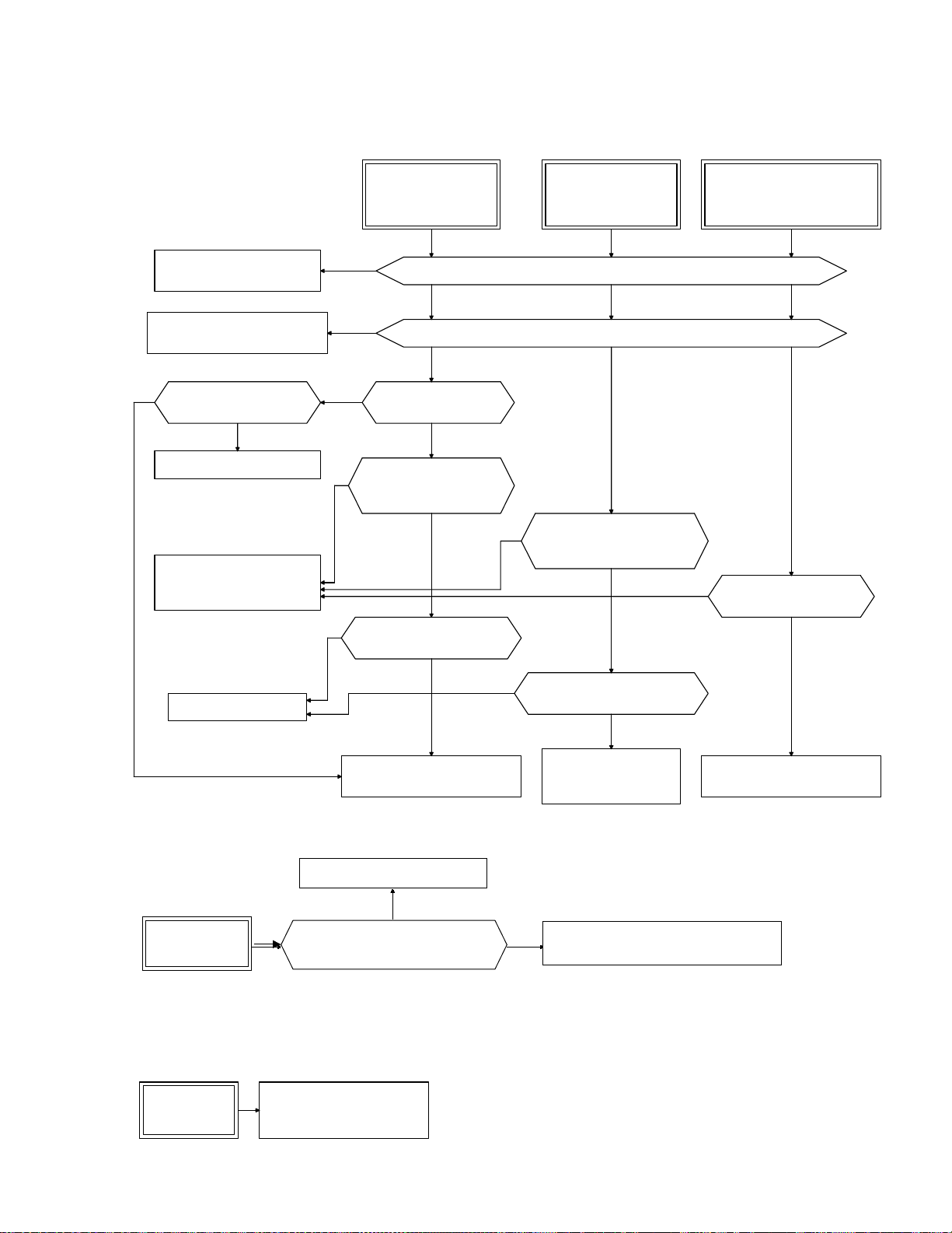
7.Trouble shooting
7.1 Protective function activation
(1) Overcurrent
Remove the short-circuit
and ground fault.
Reduce the load or increase
the inverter capacity.
NO
Can the torque boost
amount be reduced?
YES
Reduce the torque boost.
Faulty inverter or error
due to noise.
Consult with Fuji Electric.
Prolong time settings.
Overcurrent
during acceleration
YES
YES
YES
NO
NO
YES
Are the motor connecting terminals (U, V, W) short-circuited or grounded?
Is the torque boost
Is the acceleration time
setting too short
compared with the load?
Can the acceleration time
setting be prolonged?
OC1
NO
correct?
YES
YES
NO
Overcurrent
during deceleration
Is the load excessive?
Is the deceleration time
NO
setting too short compared
with the load?
YES
Can the deceleration time
setting be prolonged?
OC2
NO
NO
YES
NO
Overcurrent
running at constant speed
NO
Has the load changed
OC3
suddenly?
NONO
YES
Reduce the load or increase
the inverter capacity.
The braking method
requires inspection.
Contact Fuji Electric.
Reduce the load or increase
the inverter capacity.
(2) Ground fault
Ground fault
EF
Remove the grounded part.
Is a part in the inverter output
circuit (cable, motor) grounded?
YES
NO
Faulty inverter or error due to noise.
Contact Fuji Electric.
Note:The ground fault protective function is provided only for inverter for nominal applied motors rated at 40HP or more.
(3) Fuse brown
Fuse brown
FUS
Possible short-circuit
within the inverter.
Contact Fuji Electric.
7-1
 Loading...