

Page 1
MEH 533
1
Page 2
deal combination of power and multiple-function.
I
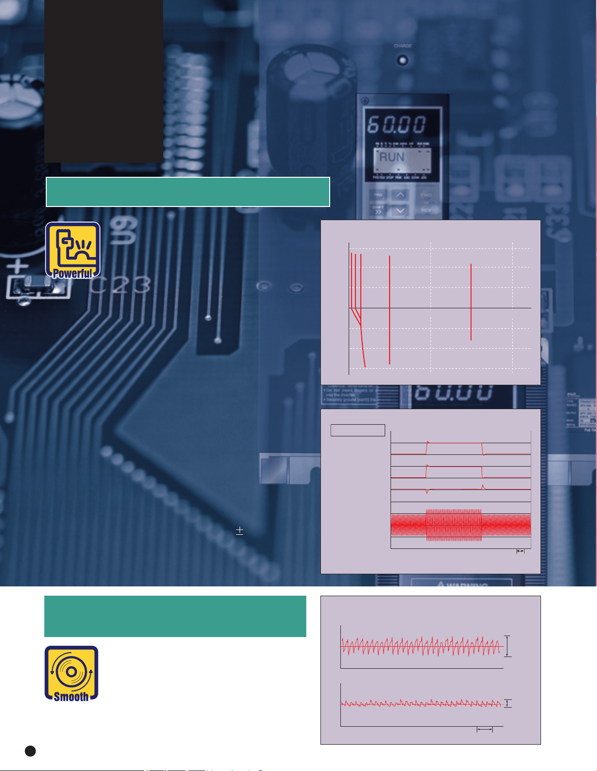
Dynamic torque-vector control promises
optimum motor control under any operating conditions.
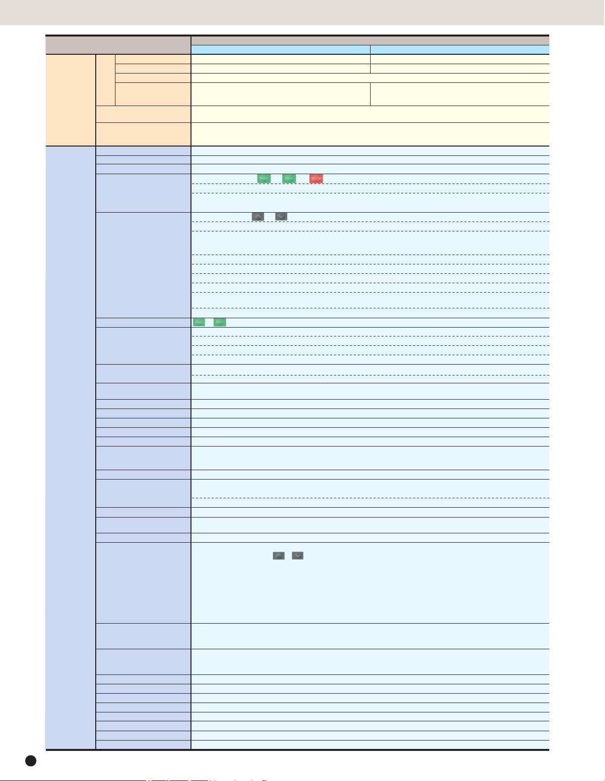
1. Dynamic torque-vector control
Dynamic torque-vector control system
performs high-speed calculation to determine the required motor power for the load
status. Our key technology is optimal
control of voltage and current vectors for
maximum output torque.
● A high starting torque of 200% at 0.5Hz.*
* 180% for 40HP or larger models.
● Achieves smooth acceleration/
deceleration in the shortest time for the
load condition.
● Using a high-speed CPU quickly
responds to an abrupt load change,
detects the regenerated power to control
the deceleration time. This automatic
decerelation function greatly reduces the
inverter tripping.
● Feedback control with PG
Enables the inverter to execute “vector
control with PG” by adding an optional PG
feedback card to obtain higher performance.
• Speed control range : 1:1200
• Speed control accuracy :
• Speed control response : 40Hz
0.02%
300
200
100
0
100
Output torque [%]
200
300
PG Vector Control
Actual torque [%]
Torque reference [%]
Motor speed [r/min]
Motor current [A]
Torque characteristics with Dynamic torque-vector control
(Sample: 5HP)
1000 2000
Motor speed
[r/min]
Step load response (Sample : 5HP)
100
0
100
0
500
400
20
0
320msTime
2. Reduced motor wow at low speed
● Motor wow at low speed (1Hz) reduced to
less than 1/2 of that achieved by
conventional inverters, with the dynamic
torque-vector control system, in
combination with the Fuji’s unique digital
AVR.
2
Wow characterisics(Sample: 5HP)
Conventional Fuji inverter
0
FRN-G11S
0
Time
14 r/min
5 r/min
500ms
Page 3
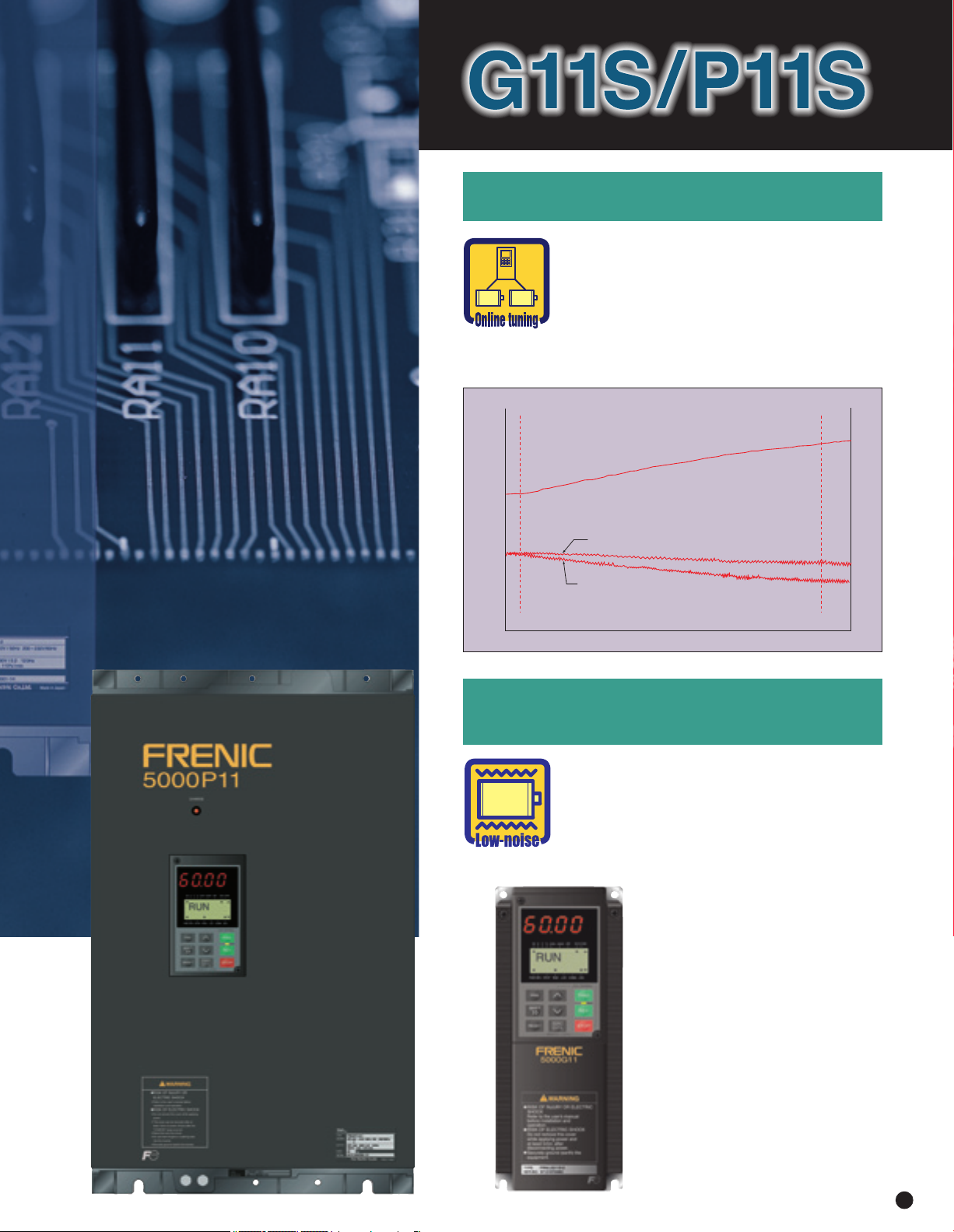
3. New on-line tuning system
● On-line tuning to continuously check for
variation of motor characteristics during
running for high-precision speed control.
● This tuning function also available for a
second motor, which allows high-precision
driving of the second motor by changeover
operation between two motors.
Motor temperature vs speed variation (Sample: 5HP)
70°C
(158°F)
30°C(86°F)
With on-line tuning
Motor speed [r/min]
Without on-line tuning
Time [min]
800
4. Environment-friendly features
● Provided with low-noise control power
supply systems which minimize noise
interference on peripheral devices such as
sensors.
● Equipped with terminals for connecting DC
REACTOR that can suppress harmonics.
● Complied with EMC Directive (Emission) when
connected to optional EMCcompliance filter.
Temperature [°C(°F)]
3
Page 4
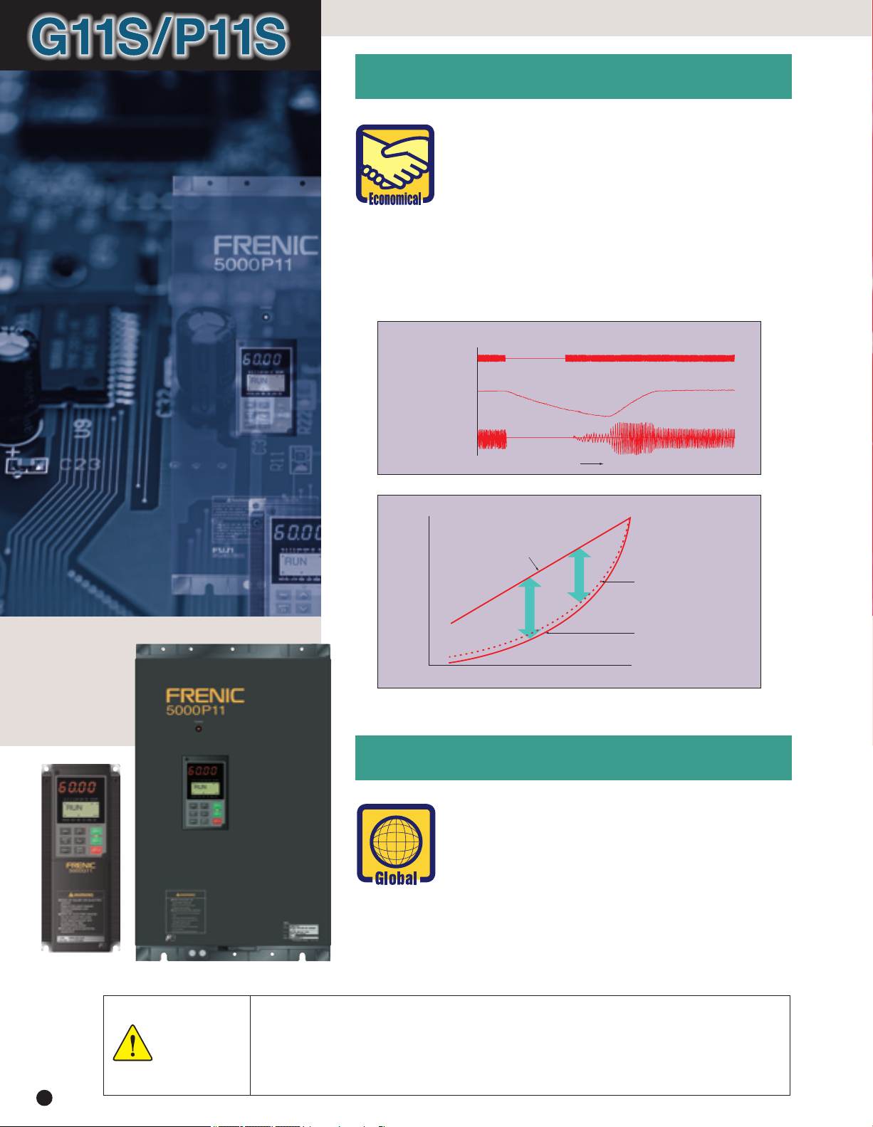
5.
Advanced, convenient functions
● 16-step speed with timer control, rotating motor
pick-up control for conveyance machinery
● Automatic energy-saving operation, PID control,
cooling fan on/off control, line/
inverter changeover operation for fans and pumps
● Rotating motor pick-up control:
Restarts motor without any shocks, by detecting motor speed
where motor is coasting after momentary power failure occurs.
● Automatic energy-saving operation function:
Minimizes inverter and motor loss at light load.
Rotating motor pick-up control characteristics (Sample:5HP)
Power source
Motor speed [r/min]
Output current [A]
Time
100
Required power [%]
0
6.
Global products, communication
Energy saving effect
Damper control
Energy
saved
Flow rate [%]
Inverter control
(V / f control)
Inverter control
(Automatic energy-saving
control)
100
● Conforms to major world safety standards: UL,
cUL, TÜV (up to 30HP), EN (CE marking)
● Equipped with RS-485 interface as standard.
● Connection to field bus: PROFIBUS-DP, Interbus-
S, DeviceNet, Modbus Plus (Option)
● Universal DI/DO : Monitors digital I/O signal
status and transmits to a host controller, helping
to simplify factory automation.
1. Use the contents of this catalog only for selecting product types and models. When using a product, read the Instruction
Manual beforehand to use the product correctly.
Safety
Precautions
4
2. Products introduced in this catalog have not been designed or manufactured for such applications in a system or equipment
that will affect human bodies or lives. Customers, who want to use the products introduced in this catalog for special systems
or devices such as for atomic-energy control, aerospace use, medical use, and traffic control, are requested to consult the
Fuji's Sales Division. Customers are requested to prepare safety measures when they apply the products introduced in this
catalog to such systems or facilities that will affect human lives or cause severe damage to property if the products become
faulty.
Page 5
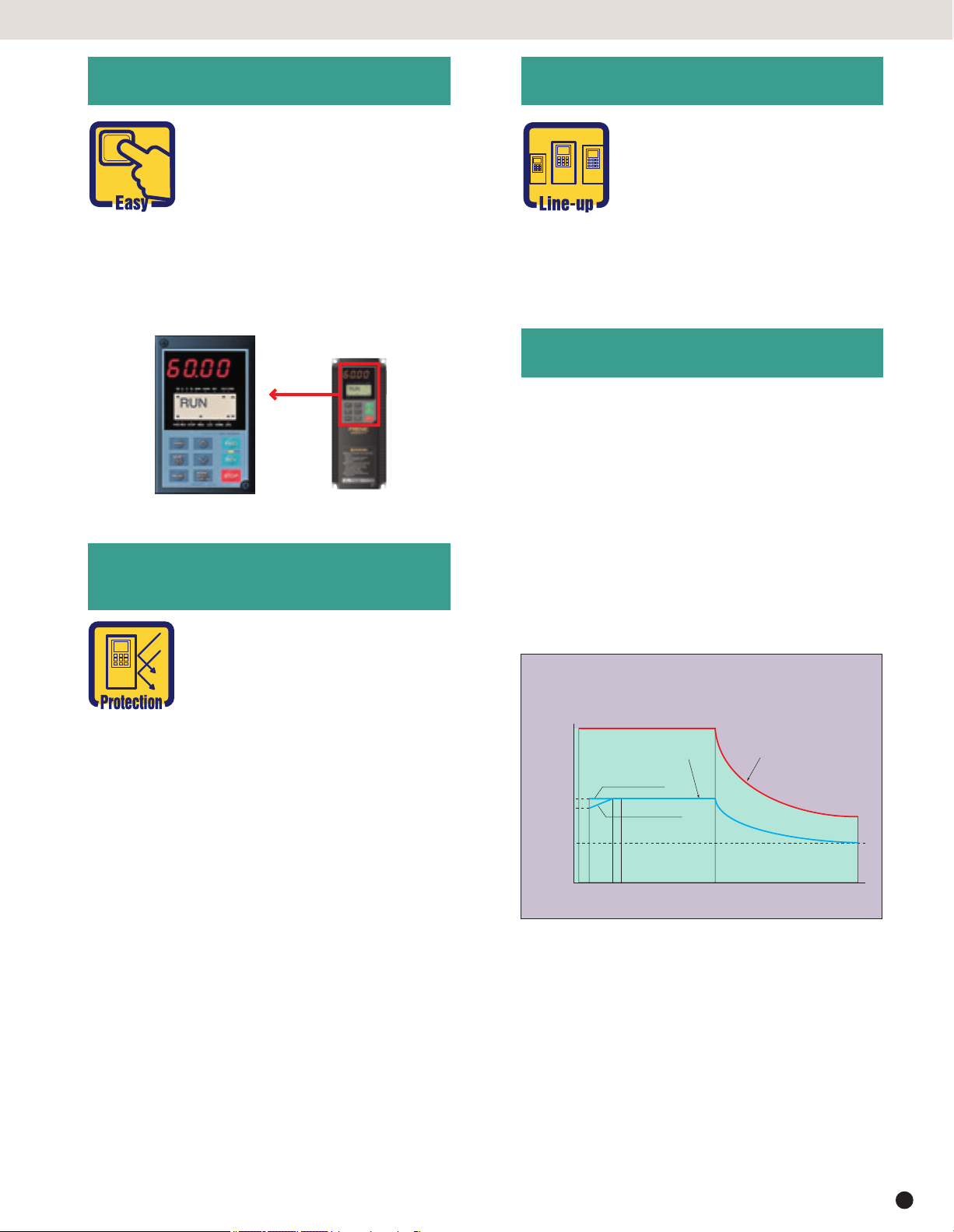
7.
Intelligent Keypad panel
G11S/P11S
9. Extensive product line
● Copy function: Easily copies
function codes and data to other
inverters.
● Six languages (English, French,
German, Italian, Spanish, and
Japanese) are available as standard.
● Jogging (inching) operation from the Keypad
or external signal
● Remote operation using optional extension
cable (CBIII-10R-¤¤¤)
8. Protective functions,
Maintenance
Protection
● Two series are available: G11S
series ranging from 1/4 to 600HP
for general industrial machines
and P11S series ranging from
7.5 to 800HP for fans and
pumps.
● Totally-enclosed casing (NEMA1) (up to 30HP
as standard).
● Optional NEMA1 enclosure available for 40HP
or larger models.
10. Other useful functions
● Side-by-side mounting (up to 30HP) saves
space when inverters are installed in a panel.
● The uniform height (10.24inch(260mm)) of
products (up to 10HP) makes it easy to design
panels.
● User-definable control terminals: Digital input (9
points), transistor output (4points), and relay
contact output (1point).
● Active drive feature: Performs prolonged
acceleration at reduced torque, monitoring the
load status to prevent tripping.
● Stall prevention function is provided as standard. Active or inactive can be also selected.
● Motors with various characteristics
can be used by setting thermal
time constant for the electronic
thermal overload protection.
● Input phase loss protective function protects
the inverter from damage caused by disconnection of power supply lines.
● Motor is protected with a PTC thermistor.
● Input terminals for auxiliary control power
supply (2HP or larger models) : Alarm signal
output will be held even if main circuit power
supply has shut down.
Excellent maintainability
The items below can be monitored on the
Keypad panel and making it easy to analyze the
cause of trip and to take preventive measures.
● Input/output terminals check
● Life expectancy of main-circuit capacitors
● Inverter on-load factor
● Accumlated operation time
● Inverter operating condition (output current,
heat sink temperature, input power, etc.)
● Detailed data on trip cause
Torque characteristics with Dynamic torque-vector control
100% of output torque refers
to the rated torque of the motor
200
Continuous operation torque
(with dynamic torque-vector control)
up to 10HP
100
90
Output torque [%]
50
1 6 1520 60 120
* The above graph shows an example of torque
characteristics when combining FRENIC5000G11S
(up to 30HP at dynamic torque-vector control) with
Fuji standard three-phase motor (8-type series, 4
poles). Continuous operation torque is for limits of
allowable load torque for using the motor within the
allowable temperature range and is not for motor
output torque.
The motor output torque is shown by the short-time
operation torque.
15 to 30HP
Output frequency [Hz]
driven at 60Hz.
Short-time operation torque
(with dynamic torque-vector control)
5
Page 6
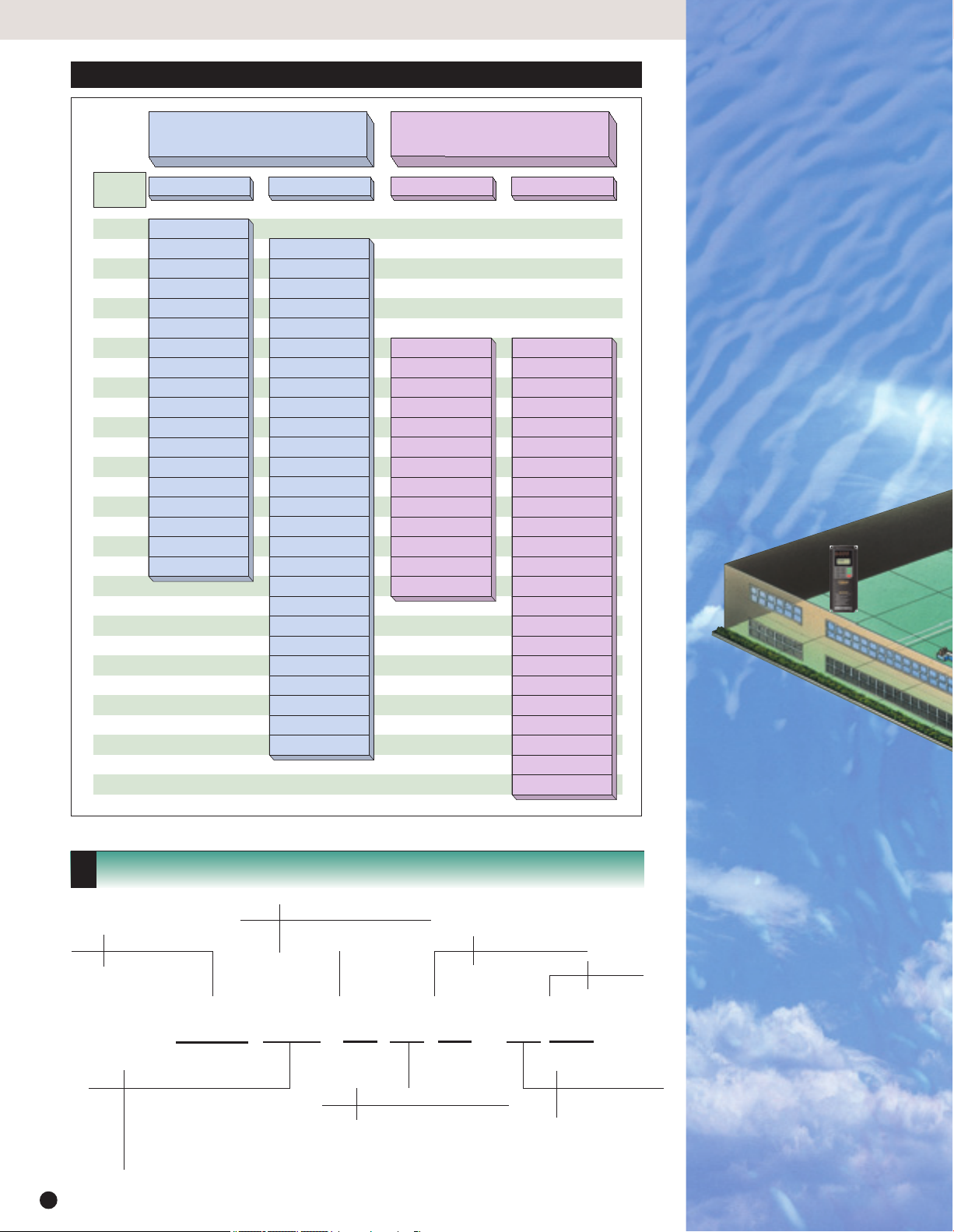
Variation
Easy to apply to customer systems. A consistent design concept in all models from 1/4HP to 800HP.
FRENIC 5000G1
industrial plant
Nominal
applied
motors [HP]
1/4
1/2
1
2
3
5
7.5
10
15
20
25
30
40
50
60
75
100
125
150
200
250
300
350
400
450
500
600
700
800
FRENIC5000G11S series
for general industrial machines
FRNF25G11S-2UX
FRNF50G11S-2UX
FRN001G11S-2UX
FRN002G11S-2UX
FRN003G11S-2UX
FRN005G11S-2UX
FRN007G11S-2UX
FRN010G11S-2UX
FRN015G11S-2UX
FRN020G11S-2UX
FRN025G11S-2UX
FRN030G11S-2UX
FRN040G11S-2UX
FRN050G11S-2UX
FRN060G11S-2UX
FRN075G11S-2UX
FRN100G11S-2UX
FRN125G11S-2UX
FRNF50G11S-4UX
FRN001G11S-4UX
FRN002G11S-4UX
FRN003G11S-4UX
FRN005G11S-4UX
FRN007G11S-4UX
FRN010G11S-4UX
FRN015G11S-4UX
FRN020G11S-4UX
FRN025G11S-4UX
FRN030G11S-4UX
FRN040G11S-4UX
FRN050G11S-4UX
FRN060G11S-4UX
FRN075G11S-4UX
FRN100G11S-4UX
FRN125G11S-4UX
FRN150G11S-4UX
FRN200G11S-4UX
FRN250G11S-4UX
FRN300G11S-4UX
FRN350G11S-4UX
FRN400G11S-4UX
FRN450G11S-4UX
FRN500G11S-4UX
FRN600G11S-4UX
FRENIC5000P11S series
for fans and pumps (variable torque loads)
460V230V460V230V
FRN007P11S-2UX
FRN010P11S-2UX
FRN015P11S-2UX
FRN020P11S-2UX
FRN025P11S-2UX
FRN030P11S-2UX
FRN040P11S-2UX
FRN050P11S-2UX
FRN060P11S-2UX
FRN075P11S-2UX
FRN100P11S-2UX
FRN125P11S-2UX
FRN150P11S-2UX
FRN007P11S-4UX
FRN010P11S-4UX
FRN015P11S-4UX
FRN020P11S-4UX
FRN025P11S-4UX
FRN030P11S-4UX
FRN040P11S-4UX
FRN050P11S-4UX
FRN060P11S-4UX
FRN075P11S-4UX
FRN100P11S-4UX
FRN125P11S-4UX
FRN150P11S-4UX
FRN200P11S-4UX
FRN250P11S-4UX
FRN300P11S-4UX
FRN350P11S-4UX
FRN400P11S-4UX
FRN450P11S-4UX
FRN500P11S-4UX
FRN600P11S-4UX
FRN700P11S-4UX
FRN800P11S-4UX
Fans
●
Air-conditioning system (for
factory, building, office,
hospital, clean room, shop,
and cattle barn)
●
Dryer
●
Boiler fan
●
Fans for controlling furnace
temperature
●
Roof fans controlled as a
group
●
Refrigerator
●
Compressor
●
Built-in blower in a filmmanufacturing machine
●
Cooling-tower fans
●
Ventilating fans
●
Air-conditioning equipment
How to read the model number
Code Series name
FRN FRENIC 5000 series
FRN F50 G 11 S - 4 UX
Code Nominal applied motors [HP]
F25 1/4HP
F50 1/2HP
001 1HP
002 2HP
to to
800 800HP
6
Code Application range
G General industrial machines
P Fans and pumps
Code Developed inverter series
11 11 series
Code Protective structure
S Standard
Code Version
UX UX
Code Input power source
2 Three-phase 230V
4 Three-phase 460V
Food processing machines
●
Food mixing machine
●
Food slicer
●
Grain milling machine
(bread, cake, noodles)
●
Tea making machine
●
Rice cleaning machine
Page 7
1S/P11S can be used for almost all
and equipment areas.
G11S/P11S
G11S/P11S
Machine tools
●
Grinding machine
●
Sanding machine
●
Milling machine
●
Lathe
●
Drilling machine
●
Tu rn ta bl e
●
Work positioning machine
●
PC board drilling machine
●
Winding machine
●
Press
Conveyance machinery
●
Crane (traveling, traversing, hoisting)
●
Automated warehouse
●
Conveyor (belt, chain, screw, roller)
●
Lift
●
Car parking facility
●
Elevator, escalator
●
Automatic door
●
Shutter equipment
●
Speed-change gear
Chemical machinery/wood
working machines
●
Fluid mixing machine
●
Extruder
●
Vibrator
●
Centrifugal separator
●
Coating machine
●
Take-up roller
●
Routing machine
●
Sanding machine
●
Planing machine
Electric pumps
●
Tankless water supply system
●
Submersible motor pump
●
Vacuum pump
●
Fountain pump
●
Cooling water pump
●
Circulating hot water pump
●
Well pump
●
Agricultural storage pump
●
Water treatment system
●
Constant-flow pump
●
Sludge pump
Packaging machinery
●
Individual packaging/innerpackaging machine
●
Packing machine
●
Outer-packaging machine
Paper making/
textile machinery
●
Spinning machine
●
Knitting machine
●
Textile printing
machine
●
Industrial sewing
machine
●
Synthetic fiber
manufacturing plant
Other machinery
●
Automated feed/medicine mixer
●
Commercial-use washing
machine
●
Offset printing press
●
Book-binding machine
●
Car-washing machine
●
Shredder
●
Dishwasher
●
Test equipment
●
Crusher
7
7
Page 8

Standard Specifications
FRENIC5000G11S 230V, for general industrial machines
Type FRN
Nominal applied motor HP
Output
ratings
Input
ratings
Control Starting torque 200% (with Dynamic torque-vector control selected)
Braking
Enclosure (
Cooling method Natural cooling Fan cooling
Standards
Weight lbs(kg)
Rated capacity *1) kVA
Rated voltage *2) V 3-phase 200V/50Hz 200, 220V, 230V/60Hz
Rated current *3) A
Overload capability 150% of rated current for 1min. 150% of rated current for 1min.
Rated frequency Hz 50, 60Hz
Phases, Voltage, Frequency 3-phase 200 to 230V 50/60Hz
Voltage / frequency variations Voltage : +10 to –15% ( Voltage unbalance *6) : 2% or less ) Frequency :+5 to –5%
Momentary voltage dip capability *7)
Rated current *8)
Required power
supply capacity *9)
Standard
Braking torque (
DC injection braking Starting frequency: 0.1 to 60.0Hz Braking time: 0.0 to 30.0s Braking level: 0 to 100% of rated current
IEC 60529
G11S-2UX
¤¤¤
(with DCR)
(without DCR)
A
kVA
Braking torque 150% 100% 20% *10) 10 to 15% *10)
Time s 10 5 5 No limit
Duty cycle % 10535 32 32 No limit
Using options
) IP 40 (NEMA1) IP 00 ( NEMA1: Option )
) 150% 100%
F50
F25
1/2
1/4
1.2
0.6
1.5 3.0 5.0 8.0 11 17 25 33 46 59 74 87 115 145 180 215 283 346
200% of rated current for 0.5s 180% of rated current for 0.5s
When the input voltage is 165V or more, the inverter can be operated continuously.
When the input voltage drops below 165V from rated voltage, the inverter can be operated for 15ms .
The smooth recovery method is selectable.
0.94 1.6 3.1 5.7 8.3 14.0 19.7 26.9 39.0 54.0 66.2 78.8 109 135 163 199 272 327
1.8 3.4 6.4 11.1 16.1 25.5 40.8 52.6 76.9 98.5 117 136 168 204 243 291 - -
0.4 0.6 1.1 2.0 2.9 4.9 6.9 9.4 14 19 23 28 38 47 57 69 95 114
-UL/cUL -Low Voltage Directive -EMC Directive TÜV (up to 30HP)
-IEC 61800-2 (Ratings, specifications for low voltage adjustable frequency a.c. power drive systems)
-IEC 61800-3 (EMC product standard including specific test methods)
4.9
4.9
(2.2)
(2.2)
001
1
2.0
5.5
(2.5)
002
2
3.2
8.4
(3.8)
003
3
4.4
8.4
(3.8)
005
5
6.8
8.4
(3.8)
010
007
10
7.5
13
9.9
13.4
13.4
(6.1)
(6.1)22(10)22(10)
015
15
18
020
20
23
025
25
29
23.1
(10.5)
030
23.1
(10.5)
040
50
40
30
36
58
46
3-phase 200 to 220V/50Hz (220 to 230V/50Hz) *5)
200 to 230V/60Hz
180% (with Dynamic torque-vector control selected)
63.9
79.4
(29)
(36)97(44)
60
72
75
86
101.4
(46)
100
113
154.3
(70)
125
138
253.5
(115)
125
100
075
060
050
FRENIC5000G11S 460V, for general industrial machines
F50
001
002
003
005
Type FRN
Nominal applied motor HP
Output
ratings
Input
ratings
Control
Braking
Enclosure (IEC 60529)
Cooling method
Standards
Weight lbs(kg)
NOTES: *1) Inverter output capacity (kVA) at 460V in 460V, 230V in 230V. *2) Output voltage is proportional to the power supply vol tage and cannot exceed the power supply
voltage. *3) Current derating may be required in case of low impedance loads such as high frequency motor. *4) When the inp ut voltage is 380V/50Hz or 380 to 415V/60Hz, the tap
of the auxiliary transformer must be changed. *5) Order individually. *6) Refer to the IEC 61800-3( 5.2.3 ). *7) Tested a t standard load condition (85% load). *8) This value is
under FUJI original calculation method. (Refer to the Technical Information.) *9) When power-factor correcting DC reactor is used. *10) With a nominal applied motor, this value is
average torque when the motor decelerates and stops from 60Hz. (It may change according to motor loss.)
8
¤¤¤
G11S-4UX
1/2
Rated capacity *1) kVA
Rated voltage *2) V
Rated current *3) A
Overload capability
Rated frequency Hz
Phases, Voltage, Frequency
Voltage / frequency variations
Momentary voltage dip
capability *7)
Rated current *8)
Required power
supply capacity *9)
Starting torque
Braking torque
Time s
Duty cycle %
Standard
Braking torque (Using options)
DC injection braking
(with DCR)
A
(without DCR)
1.2
3-phase 380, 400, 415V/50Hz 380, 400, 440, 460V/60Hz
1.5
150% of rated current for 1min.
200% of rated current for 0.5s
50, 60Hz
3-phase 380 to 480V 50/60Hz 3-phase 380 to 440V/50Hz 380 to 480V/60Hz *4)
Voltage : +10 to –15% ( Voltage unbalance *6) : 2% or less ) Frequency :+5 to –5%
When the input voltage is 310V or more, the inverter can be operated continuously.
When the input voltage drops below 310V from rated voltage, the inverter can be operated for 15ms.
The smooth recovery method is selectable.
0.82
1.8
0.6
kVA
200% (with Dynamic torque-vector control selected)
150%
5
Starting frequency: 0.1 to 60.0Hz Braking time: 0.0 to 30.0s Braking level: 0 to 100% of rated current
Natural cooling
-UL/cUL -Low Voltage Directive -EMC Directive TÜV (up to 30HP)
-IEC 61800-2 (Ratings, specifications for low voltage adjustable frequency a.c. power drive systems)
-IEC 61800-3 (EMC product standard including specific test methods)
4.9
(2.2)
(2.5)
1
2
2.0
2.9
2.5
3.7
1.5
2.9
3.5
6.2
1.1
2.1
35532
5.5
8.4
(3.8)
(3.8)
007
3
5
4.4
7.2
5.5
9
4.2
7.1
10.0
9.2
14.9
21.5
3.0
5.0
100% 20% *10)
5 No limit
150% 100%
IP 40 (NEMA1) IP 00 ( NEMA1: Option )
8.4
8.4
14.3
(3.8)
(6.5)
010
7.5
10
10
14
13
18
13.5
27.9
7.0
9.4
14.3
(6.5)22(10)22(10)
015
15
19
24
19.8
39.1
14
020
20
24
30
26.8
50.3
19
025
25
31
39
33.2
59.9
24
23.1
(10.5)
030
040
050
060
075
100
125
150
200
250
30
40
50
60
75
100
125
150
200
250
36
48
60
73
89
120
140
167
202
242
45
60
75
91
112
150
176
210
253
304
150% of rated current for 1min.
180% of rated current for 0.5s
39.3
54
67
81
100
134-160-196-232-282-352-385-491-552-624-704
69.3
86
104
124
150
28
38
47
57
70
93 111 136 161 196 244 267 341 383 433 488
180% (with Dynamic torque-vector control selected)
10 to 15% *10)
No limit32
Fan cooling
23.1
63.9
(29)75(34)86(39)
(10.5)
88.2
(40)
105.8
(48)
154.3
(70)
154.3
(70)
220.5
(100)
220.5
(100)
300
300
300
377
308.6
(140)
350
350
331
415
308.6
(140)
400
400
414
520
551.2
(250)
450
450
466
585
551.2
(250)
500
500
518
650
793.7
(360)
600
600
590
740
-
793.7
(360)
Page 9
G11S/P11S
FRENIC5000P11S 230V, for fans and pumps
100
075
060
050
040
030
Type
Nominal applied motor HP
Output
ratings
Input
ratings
Control Starting torque 50%
Braking
Enclosure (IEC 60529) IP 40 (NEMA1) IP 00 ( NEMA1 : Option )
Cooling method Fan cooling
Standards
Weight lbs(kg)
FRN
¤¤¤
P11S-2UX
Rated capacity *1) kVA
Rated voltage *2) V 3-phase 200V/50Hz 200, 220V, 230V/60Hz
Rated current *3) A 22 29 42 55 67 78 115 145 180 215 283 346 415
Overload capability 110% of rated current for 1min
Rated frequency Hz 50, 60Hz
Phases, Voltage, Frequency 3-phase 200 to 230V 50/60Hz
Voltage / frequency variations Voltage : +10 to –15% ( Voltage unbalance *6) : 2% or less ) Frequency :+5 to –5%
Momentary voltage dip capability *7)
Rated current *8)
Required power
supply capacity *9)
Braking torque *10) 20% 10 to 15%
Time s No limit
Duty cycle % No limit
Standard
Braking torque (Using options) 100% 70%
DC injection braking Starting frequency: 0.1 to 60.0Hz Braking time: 0.0 to 30.0s Braking level: 0 to 80% of rated current
(with DCR) 19.7 26.9 39.0 54.0 66.2 78.8 109 135 163 199 272 327 400
A
(without DCR) 40.8 52.6 76.9 98.5 117 136 168 204 243 291
007
7.5
8.8
When the input voltage is 165V or more, the inverter can be operated continuously.
When the input voltage drops below 165V from rated voltage, the inverter can be operated for 15ms .
The smooth recovery method is selectable.
kVA 6.9 9.4 14 19 23 28 38 47 57 69 95 114 139
-UL/cUL -Low Voltage Directive -EMC Directive TÜV (up to 30HP)
-IEC 61800-2 (Ratings, specifications for low voltage adjustable frequency a.c. power drive systems)
-IEC 61800-3 (EMC product standard including specific test methods)
12.6
(5.7)
015
010
12.6
(5.7)
15
10
17
12
12.6
(5.7)22(10)22(10)
020
20
22
025
25
27
30
46
31
3-phase 200 to 220V/50Hz (220 to 230V/50Hz) *5) 200 to 230V/60Hz
23.1
63.9
(10.5)
(29)
63.9
58
(29)
72
79.4
(36)97(44)
86
113
---
101.4
(46)
100
75
60
50
40
125
125
138
154.3
(70)
150
150
165
253.5
(115)
FRENIC5000P11S 460V, for fans and pumps
007
010
015
020
025
030
040
050
060
075
100
125
150
200
250
300
350
400
450
500
600
700
700
668
793.7
(360)
800
800
764
-
793.7
(360)
Type FRN
Nominal applied motor HP
Output
ratings
Input
ratings
Control
Braking
Enclosure (IEC 60529)
Cooling method
Standards
Weight lbs(kg)
NOTES: *1) Inverter output capacity (kVA) at 460V in 460V, 230V in 230V. *2) Output voltage is proportional to the power supply vol tage and cannot exceed the power supply
voltage. *3) Current derating may be required in case of low impedance loads such as high frequency motor. *4) When the inp ut voltage is 380V/50Hz or 380 to 415V/60Hz, the tap
of the auxiliary transformer must be changed. *5) Order individually. *6) Refer to the IEC 61800-3( 5.2.3 ). *7) Tested a t standard load condition (85% load). *8) This value is
under FUJI original calculation method. (Refer to the Technical Information.) *9) When power-factor correcting DC reactor (DC R) is used. *10) With a nominal applied motor, this
value is average torque when the motor decelerates and stops from 60Hz. (It may change according to motor loss.)
¤¤¤
P11S-4UX
7.5
10
15
20
25
30
40
50
60
75
100
125
10
13
18
24
29
35
48
60
72
89
119
Rated capacity *1) kVA
Rated voltage *2) V
Rated current *3) A
Overload capability 110% of rated current for 1min
Rated frequency Hz 50, 60Hz
Phases, Voltage, Frequency
Voltage / frequency variations
Momentary voltage
dip capability *7)
Rated current *8)
Required power
supply capacity *9)
Starting torque 50%
Braking torque *10)
Time s
Duty cycle %
Standard
Braking torque (Using options)
DC injection braking
(with DCR)
A
(without DCR)
3-phase 380, 400, 415V/50Hz 380, 400, 440, 460V/60Hz
16.5 23 30 37 44 60 75 91 112 150 176 210 253 304 377 415 485 520 650 740 840 960
12.5
3-phase 380 to 480V 50/60Hz
Voltage : +10 to –15% ( Voltage unbalance *6) : 2% or less ) Frequency :+5 to –5%
When the input voltage is 310V or more, the inverter can be operated continuously.
When the input voltage drops below 310V from rated voltage, the inverter can be operated for 15ms.
The smooth recovery method is selectable.
13.5
19.8
26.8
10.0
27.9
21.5
7.0
kVA
Starting frequency: 0.1 to 60.0Hz Braking time: 0.0 to 30.0s Braking level: 0 to 80% of rated current
-UL/cUL -Low Voltage Directive -EMC Directive TÜV (up to 30HP)
-IEC 61800-2 (Ratings, specifications for low voltage adjustable frequency a.c. power drive systems)
-IEC 61800-3 (EMC product standard including specific test methods)
13.4
(6.1)
39.1
9.4
14
20% 10 to 15%
IP 40 (NEMA1) IP 00 ( NEMA1 : Option )
13.4
13.4
(6.1)
(6.1)22(10)22(10)
33.2
50.3
59.9
19
24
100% 70%
3-phase 380 to 440V/50Hz 380 to 480V/60Hz *4)
39.3
54
67
81
100
69.3
86
104
124
150
28
38
47
57
70
63.9
23.1
(10.5)
63.9
(29)
(29)75(34)86(39)
140
134-160-196-232-282-352-385-491-552-624-704-792-880
93 111 136 161 196 244 267 341 383 433 488 549 610
No limit
No limit
Fan cooling
88.2
105.8
(48)
(40)
150
167
154.3
(70)
200
201
154.3
(70)
250
242
220.5
(100)
300
300
220.5
(100)
350
330
308.6
(140)
400
386
308.6
(140)
450
414
308.6
(140)
500
517
551.2
(250)
600
589
551.2
(250)
9
Page 10
Common Specifications
Item
Output
frequency
Control
Note: (*) Option *1) Inverter may automatically reduce carrier frequency, in accordance with ambient temperature or output current for protecting inverter.
10
Maximum frequency
Base frequency
Starting frequency
Carrier frequency *1)
Setting
Accuracy (Stability)
Setting resolution
Control method
Voltage / freq. (V/f) characteristic
Torque boost
Operation method
Frequency setting
(Frequency command)
Jogging operation
Running status signal
Acceleration / Deceleration time
Active drive
Frequency limiter
Bias frequency
Gain for frequency setting
Jump frequency control
Rotating motor pick up (Flying start)
Auto-restart after momentary power
failure
Line / Inverter changeover operation
Slip compensation
Droop operation
Torque limiting
Torque control
PID control
Automatic deceleration
Second motor’s setting
Energy saving operation
Fan stop operation
Universal DI
Universal DO
Universal AO
Zero speed control (*)
Positioning control (*)
Synchronized operation (*)
0.75 to 15kHz (75HP or smaller)
0.75 to 10kHz (100HP or larger)
• Analog setting : ±0.2% of Maximum frequency (at 25±10°C(77±50°F))
• Digital setting : ±0.01% of Maximum frequency (at –10 to +50°C(14 to 122°F))
• Analog setting : •
• Digital setting : 0.01Hz at Maximum frequency of up to 99.99Hz (0.1Hz at Maximum frequency of 100Hz and above)
• LINK setting : • 1/20000 of Maximum frequency ex.) 0.003Hz at 60Hz, 0.006Hz at 120Hz, (0.02Hz at 400Hz: G11S) • 0.01Hz (Fixed)
• V/f control (Sinusoidal PWM control) • Dynamic torque-vector control (Sinusoidal PWM control) • Vector control with PG (*) (G11S only)
Adjustable at base and maximum frequency, with AVR control : 320 to 480V (460V), 80 to 240V (230V)
Selectable by load characteristics: Constant torque load (Auto/manual), Variable torque load (Manual)
• KEYPAD operation : or key, key
• Digital input signal operation : FWD or REV command, Coast-to-stop command, etc.
• LINK operation : RS-485 (Standard)
• KEYPAD operation: or key
• External potentiometer (*) : 1 to 5kΩ (1/2W)
• Analog input : 0 to +10V DC (0 to +5V DC), 4 to 20mA DC
(Reversible)
• UP/DOWN control : Output frequency increases when UP signal is ON, and decreases when DOWN signal is ON.
• Multistep frequency : Up to 16 different frequencies can be selected by digital input signal.
• Pulse train input (*) : 0 to 100kp/s
• Digital signal (parallel ) (*) : 16-bit binary
• LINK operation : RS-485 (Standard)
• Programmed PATTERN operation: Max. 7 stages
Transistor output (4 points) : RUN, FAR, FDT, OL, LU, TL, etc.
Relay output (2 points) : • Same as transistor output • Alarm output (for any fault)
Analog output (1 point) : Output frequency, Output current, Output torque, etc.
Pulse output (1 point) : Output frequency, Output current, Output torque, etc.
0.01 to 3600s : • Independently adjustable acceleration and deceleration • 4 different times are selectable.
Mode select : Linear, S-curve (weak), S-curve (strong), Non-linear
When the acceleration time reaches 60s, the motor output torque is automatically reduced to rated torque. Then the motor operation mode is changed to torque limiting operation.
The acceleration time is automatically extended up to 3 times.
High and Low limiter can be preset.
Bias frequency can be preset.
Gain for frequency setting can be preset. (0.0 to 200.0%) ex.) Analog input 0 to +5V DC with 200% gain results in maximum frequency at 5V DC.
Jump frequency (3 points) and its common jump hysteresis width (0 to 30Hz) can be preset.
A rotating motor (including inverse rotating mode) can be smoothly picked up without stopping the motor (speed search method).
Automatic restart is available without stopping motor after a momentary power failure (speed search method). When "Smooth recovery" mode is
selected, the motor speed drop is held minimum. (The inverter searches the motor speed, and smoothly returns to setting frequency. Even if the motor
circuit is temporarily opened, the inverter operates without a hitch. )
Controls the switching operation between line power and inverter. The inverter has sequence function inside.
The inverter output frequency is controlled according to the load torque to keep motor speed constant. When the value is set at
"0.00" and "Torque-vector" is set at "active", the compensation value automatically selects the Fuji standard motor.
Slip compensation can be preset for the second motor.
The motor speed droops in proportion to output torque (–9.9 to 0.0Hz)......G11S only.
•
• Torque limiting 1 and 2 can be individually set, and are selectable with a digital input signal.
Output torque (or load factor) can be controlled with an analog input signal.....G11S only.
This function can control flowrate, pressure, etc. (with an analog feedback signal.)
• Reference• KEYPAD operation ( or key) : Setting freq. / Max. freq. X 100 (%)• PATTERN operation
signal • Voltage input (Terminal 12 ) : 0 to +10V DC • DI option input (*): •
• Feedback signal • Terminal 12 (0 to +10V DC or +10 to 0V DC)
Torque limiter 1 (Braking) is set at "F41: 0" (Same as Torque limiter 2 (Braking) ).
•
• In constant speed operation : Based on regenerative energy, the frequency is increased and tripless operation is active.
This function is used for two motors switching operation.
• The second motor’s V/f characteristics (base and maximum frequency) can be preset.
• The second motor’s circuit parameter can be preset. Torque-vector control can be applied to both motors.
This function minimizes inverter and motor losses at light load.
This function is used for silent operation or extending the fan's lifetime.
Transmits to main controller of LINK operation.
Outputs command signal from main controller of LINK operation.
Outputs analog signal from main controller of LINK operation.
The stopped motor holds its rotor angle.....G11S only.
The SY option card can be used for positioning control by differential counter method.
This function controls the synchronize operation between 2 axes with PGs.
(Inverse)
or key, FWD or REV digital input signal
When the motor torque reaches a preset limiting level, this function automatically adjusts the output frequency to prevent the inverter from tripping due to an overcurrent.
• Current input (Terminal C1 ) : 4 to 20mA DC • Binary, full scale/
Reversible operation with polarity (Terminal 12)
•
•
Reversible operation with polarity (Terminal 12 + V1 )
• Inverse mode operation (Terminal 12 ) : +10 to 0V DC
• Inverse mode operation (Terminal C1 ) : 20 to 4mA DC
In deceleration : The deceleration time is automatically extended up to 3 times the setting time for tripless operation even if braking resistor not used.
G11S
50 to 400Hz
25 to 400Hz
1/1000 of Maximum frequency ex.) 0.06Hz at 60Hz, 0.12Hz at 120Hz, (0.4Hz at 400Hz: G11S) • 1/3000 for 40HP and above
T-Link (FUJI private link), PROFIBUS-DP, Interbus-S, DeviceNet, Modbus Plus, JPCN1 (Option)
0 to ±10V DC (0 to ± 5V DC) ....Reversible operation by polarized signal can be selected.
+10 to 0V DC, 20 to 4mA DC......Inverse mode operation can be selected.
T-Link (FUJI private link), RPOFIBUS-DP, Interbus-S, DeviceNet, Modbus Plus, JPCN1 (Option)
• Terminal C1 (4 to 20mA DC or 20 to 4mA DC)
0.1 to 60Hz, Holding time: 0.0 to 10.0s
Explanation
: 0 to ±10V DC •
: 0 to ±10V DC •
P11S
50 to 120Hz
25 to 120Hz
0.75 to 15kHz (30HP or smaller)
0.75 to 10kHz (40 to 100HP)
0.75 to 6kHz (125HP or larger)
: Setting freq./Max. freq. X 100 (%)
BCD, setting freq./Max. freq. X
Multistep frequency setting
RS-485
: Setting freq./Max. freq. X 100 (%)
: Setting freq./Max. freq. X 100 (%)
100
(%)
100
(%)
Page 11
G11S/P11S
Item
Indication
Protection
Condition
(Installation
and
operation)
Storage condition -Temperature : –25 to +65 °C(-13 to 149°F), -Humidity : 5 to 95%RH (non-condensing)
Operation mode (Running)
• Output frequency 1 (Before slip compensation) (Hz)
• Output frequency 2 (After slip compensation) (Hz)
• Setting frequency (Hz)
• Output current (A)
• Output voltage (V)
• Motor synchronous speed (r/min)
• Line speed (m/min)
• Load shaft speed (r/min)
• Torque calculation value (%)
• Input power (kW)
• PID reference value
• PID reference value (remote)
• PID feedback value
• Trip histor y
Stopping
Trip mode
Charge lamp
Overload
Overvoltage
Undervoltage
Input phase loss
Overheating
Short-circuit
Ground fault
Motor overload
DB resistor overheating
Stall prevention
Output phase loss
Motor protection by PTC thermistor When the motor temperature exceeds allowable value, the inverter trips automatically.
Auto reset
Installation location*
Altitude 3300ft(1000m) or less. Applicable to 9800ft(3000m) with power derating (-10%/3300ft(1000m))
Ambient temperature
Ambient humidity 5 to 95%RH (non-condensing)
Vibration
Selected setting value or output value
Displays the cause of trip by codes as follows.
• OC1 (Overcurrent during acceleration)
• OC2 (Overcurrent during deceleration)
• OC3 (Overcurrent during running at constant speed)
• EF (Ground fault)
• Lin (Input phase loss)
• FUS (Fuse blown)
• OU1 (Overvoltage during acceleration)
• OU2 (Overvoltage during deceleration)
• OU3 (Overvoltage running at constant speed)
• LU (Undervoltage)
• OH1 (Overheating at heat sink)
• OH2 (External thermal relay tripped)
• OH3 (Overtemperature at inside air)
• dBH (Overheating at DB circuit)
• OL1 (Motor 1 overload)
• OL2 (Motor 2 overload)
• OLU (Inverter unit overload)
• OS (Overspeed)
• PG (PG error)
• Er1 (Memory error)
• Er2 (KEYPAD panel communication error)
• Er3 (CPU error)
• Er4 (Option error)
• Er5 (Option error)
• Er6 (Operation procedure error)
• Er7 (Output phase loss error, impedance imbalance)
• Er7. (Charging circuit alarm, 40HP or larger)
• Er8 (RS-485 error)
When the DC link circuit voltage is higher than 50V, the charge lamp is ON.
Protects the inverter by electronic thermal overload function and by detection of inverter temperature.
Detects DC link circuit overvoltage,and stops the inverter. (460V : 800V DC, 230V : 400V DC)
Detects DC link circuit undervoltage,and stops the inverter. (460V : 400V DC, 230V : 200V DC)
Phase loss protection for power line input.
Protects the inverter by detection of inverter temperature.
Short-circuit protection for inverter output circuit
• Ground fault protection for inverter output circuit (3-phase current detection method) • Zero-phase current detection method (40HP or larger)
• The inverter trips,and then protects the motor. • Electronic thermal overload protection can be set for standard motor or inverter motor
• Thermal time constant (0.5 to 75.0 minutes) can be preset for a special motor.
• The second motor's electronic thermal overload protection can be preset for 2-motor changeover operation.
• Prevents DB resistor overheating by internal electronic thermal overload relay (10HP or smaller).
• Prevents DB resistor overheating by external thermal overload relay attached to DB resistor (15HP or larger).
(The inverter stops electricity discharge operation to protect the DB resistor.)
• Controls the output frequency to prevent (overcurrent) trip when the output current exceeds the limit value during acceleration.
• Lowers the output frequency to hold almost constant torque when the output current exceeds the limit value during operation at constant speed.
• Controls the output frequency to prevent (overvoltage) trip when the DC link circuit voltage exceeds the limit value during deceleration.
When the inverter executes auto-tuning, detects each phase impedance imbalance.
When the inverter is tripped, it resets automatically and restarts.
Free from corrosive gases, flammable gases, oil mist, dusts, and direct sunlight.
Indoor use only.
–10 to +50 °C(14 to 122°F). For inverters of 30HP or smaller, remove the ventilation covers when operating it at a temperature of 40°C(104°F) or above.
3mm at from 2 to less than 9Hz, 9.8m/s
2m/s2 at from 20 to less than 55Hz (2m/s2 at from 9 to less than 55Hz :G11S 125HP, P11S 150HP or more)
1m/s
:Cause of trip by code (Even when main power supply is off,
trip history data of the last 4 trips are retained.)
2
at from 55 to less than 200Hz,
LED monitor
2
at from 9 to less than 20Hz,
Explanation
LCD monitor
Operation monitor
• Displays operation guidance
• Bargraph: Output frequency (%), Output current (A), Output torque (%)
Alarm monitor
• The alarm data is displayed when the inverter trips.
Function setting
Displays function codes and its data or data code, and changes the data value.
Operation condition
• Output frequency (Hz)
• Output current (A)
• Output voltage (V)
• Torque calculation value (%)
• Setting frequency (Hz)
• Operation condition
(FWD / REV, IL, VL / LU, TL)
Tester function
(I/O check)
• Digital I/O : (ON), (OFF)
• Analog I/O: (V), (mA), (H), (p/s)
Maintenance data
• Operation time (h)
• DC link circuit voltage (V)
• Temperature at inside air (°C)
• Temperature at heat sink (°C)
• Maximum current (A)
• Main circuit capacitor life(%)
• Control PC board life (h)
Load factor calculation
• Measurement time (s)
• Maximum current (A)
Alarm data
• Output frequency (Hz)
• Output current (A)
• Output voltage (V)
• Torque calculation value (%)
• Setting frequency (Hz)
• Operation condition
(FWD / REV, IL, VL / LU, TL)
• Operation time (h)
• DC link circuit voltage (V)
* If the inverter has to be used in an atmosphere including
(Japanese, English, German, French, Spanish, Italian)
Operation monitor & Alarm monitor
Function setting & monitor
• Motor synchronous speed (r/min)
• Load shaft speed (r/min)
• Line speed (m/min)
• PID reference value
• PID feedback value
Driving torque limiter setting vaiue (%)
•
• Braking togue limiter setting value
• Cooling fan operation time (h)
• Communication error times
(KEYPAD,RS-485, Option)
• ROM version
(Inverter, KEYPAD, Option)
• Average current (A)
• Average braking power (%)
• Temperature at inside air (°C)
• Hest sink temperature (°C)
• Communication error times
(KEYPAD,RS-485, Option)
• Digital input terminal condition
(Remote, Communication)
• Transistor output terminal condition
• Trip history code
• Multiple alram exist
the hydrogen sulfide gases, a special model might be available.
Contact Fuji Electric FA.
(%)
11
Page 12

Terminal Functions
Terminal Functions
12
Main
circuit
Analong
input
Digital
input
Symbol
L1/R, L2/S,L3/T
U, V, W
P1, P(+)
P(+), N(-)
P(+), DB
G
R0, T0
13
12
V2
C1
11
FWD
REV
X1
X2
X3
X4
X5
X6
X7
X8
X9
(SS1)
(SS2)
(SS4)
(SS8)
(RT1)
(RT2)
(HLD)
(BX)
(RST)
(THR)
(JOG)
(Hz2/Hz1)
(M2/M1)
(DCBRK)
(TL2/TL1)
(SW50)
(SW60)
(UP)
(DOWN)
(WE-KP)
(Hz/PID)
(IVS)
(IL)
(Hz/TRQ)
(LE)
(U-DI)
(STM)
(PG/Hz)
(SYC)
(ZERO)
(STOP1)
(STOP2)
(EXITE)
PLC
CM
Terminal name
Power input
Inverter output
For DC REACTOR
For BRAKING UNIT
For EXTERNAL
BRAKING RESISTOR
Grounding
Auxiliary control
power supply
Potentiometer power supply
Voltage input
(Torque control)
(PID control)
(PG feedback)
Voltage input
Current input
(PID control)
Common
Forward operation
command
Reverse operation
command
Digital input 1
Digital input 2
Digital input 3
Digital input 4
Digital input 5
Digital input 6
Digital input 7
Digital input 8
Digital input 9
Multistep freq.
selection
ACC / DEC time selection
3-wire operation
stop command
Coast-to-stop
command
Alarm reset
Trip command
(External fault)
Jogging operation
Freq. set 2 / Freq. set 1
Motor 2 / Motor 1
DC brake command
Torque limiter 2 /
Torque limiter 1
Switching operation
between line and inverter
UP command (UP) - CM: ON ..... The output frequency increases.
DOWN command
Write enable for KEYPAD
PID control cancel
Inverse mode changeover
Interlock signal for 52-2
TRQ control cancel
Link enable (RS-485, Bus)
Universal DI This signal is transmitted to main controller of LINK operation.
Pick up start mode
SY-PG enabled
Syuhronization command
Zero speed command
Forced stop command
Forced stop command
with Deceleration time4
Pre-exciting command:
PLC terminal
Common
Connect a 3-phase power supply.
Connect a 3-phase induction motor.
Connect the DC REACTOR for power-factor correcting or harmonic current reducing.
• Connect the BRAKING UNIT (Option).
• Used for DC bus connection system.
Connect the EXTERNAL BRAKING RESISTOR (Option)
Ground terminal for inverter chassis (housing).
Connect the same AC power supply as that of the main circuit to back up the control circuit
power supply.
+10V DC power supply for frequency setting POT ( POT: 1 to 5kΩ )
• 0 to +10V DC/0 to 100% (0 to +5V DC/0 to 100% )
• Reversible operation can be selected by function setting.
0 to ±10V DC /0 to ±100% (0 to ±5V DC/0 to ±100% )
• Inverse mode operation can be selected by function setting or digital input signal.
+10 to 0V DC/0 to 100%
Used for torque control reference signal.
Used for PID control reference signal or feedback signal.
Used for reference signal of PG feedback control (option)
Frequency is set according to the analog input voltage supplied from an external circuit
• 0 to +10V DC/0 to 100% • Reverse operation: +10 to 0V DC/0 to 100%
* It can be used only one terminal "V2" or "C1" alternatively * Input resistance: 22kΩ
• 4 to 20mA DC/0 to 100%
• Inverse mode operation can be selected by function setting or digital input signal.
20 to 4mA DC/0 to 100%
Used for PID control reference signal or feedback signal.
Common for analog signal
FWD - CM: ON ..... The motor runs in the forward direction.
FWD - CM: OFF ..... The motor decelerates and stops.
REV - CM: ON ..... The motor runs in the reverse direction.
REV - CM: OFF ..... The motor decelerates and stops.
These terminals can be preset as follows.
(SS1) : 2 (0, 1) different frequencies are selectable.
(SS1,SS2) : 4 (0 to 3) different frequencies are selectable.
(SS1,SS2,SS4) : 8 (0 to 7) different frequencies are selectable.
(SS1,SS2,SS4,SS8) : 16 (0 to 15) different frequencies are selectable.
(RT1) : 2 (0, 1) different ACC / DEC times are selectable.
(RT1,RT2) : 4 (0 to 3) different ACC / DEC times are selectable.
Used for 3-wire operation.
(HLD) - CM: ON ..... The inverter self-holds FWD or REV signal.
(HLD) - CM: OFF ..... The inverter releases self-holding.
(BX) - CM: ON ..... Motor will coast-to-stop. (No alarm signal will be output.)
(RST) - CM: ON ..... Faults are reset. (This signal should be held for more than 0.1s.)
(THR) - CM: OFF ..... "OH2 trip" occurs and motor will coast-to-stop.
(JOG) - CM: ON ..... JOG frequency is effective.
(Hz2/Hz1) - CM: ON ..... Freq. set 2 is effective.
(M2/M1) - CM: ON ..... The motor circuit parameter and V/f characteristics are changed
(DCBRK) - CM: ON ..... The DC injection brake is effective. (In the inverter deceleration mode)
(TL2/TL1) - CM: ON ..... Torque limiter 2 is effective.
(SW50(SW60)) - CM: ON .....The motor is changed from inverter operation to line operation.
(SW50(SW60)) - CM: OFF ..... The motor is changed from line operation to inverter operation.
(DOWN) - CM: ON ..... The output frequency decreases.
• The output frequency change rate is determined by ACC / DEC time.
• Restarting frequency can be selected from 0Hz or setting value at the time of stop.
(WE-KP) - CM: ON ..... The data is changed by KEYPAD.
(Hz/PID) - CM: ON ..... The PID control is canceled,and frequency setting by KEYPAD
( or )is effective.
(IVS) - CM: ON ..... Inverse mode is effective in analog signal input.
Connect to auxiliary contact (1NC) of 52-2.
(Hz/TRQ) - CM: ON ..... The torque control is canceled, and ordinary operation is effective.
(LE) - CM: ON ..... The link opereation is effective. Used to switch operation between ordinary
(STM) - CM: ON ..... The "Pick up" start mode is effective.
(PG/Hz) - CM: ON ..... Synchronized operation or PG-feedback operation is effective.
(SYC) - CM: ON ..... The motor is controlled for synchronized operation between 2 axes with PGs.
(ZERO) - CM: ON ..... The motor decelerates and holds its rotor angle.
(STOP1) - CM: ON ..... The motor decelerates and stops.
(STOP2) - CM: ON ..... The motor decelerates and stops with Deceleration time4.
(EXITE) - CM: ON ..... The magnetic flux can be established preliminary before starting at PG
Connect PLC power supply to avoid malfunction of the inveter that has SINK type digital
input,when PLC power supply is off.
Common for digital signal
to the second motor's ones.
operation and link operation to communication.
vector mode.
Function
Remarks
DC REACTOR: 75HP or smaller : Option
BRAKING UNIT (Option): G11S: 15HP or larger, P11S: 20HP or larger
G11S : 10HP or smaller, P11S : 15HP or smaller
1HP or smaller: Not correspond
• Allowable maximum output current : 10mA
• Input impedance: 22kΩ
• Allowable maximum input voltage: ±15V DC
• If input voltage is 10 to 15V DC, the inverter estimates
it to10V DC.
• Input impedance:250kΩ
• Allowable maximum input current: 30mA DC
• If input current is 20 to 30mA DC , the inverter estimates
it to20mA DC.
Isolated from terminals CME and CM.
When FWD and REV are simultaneously ON,the motor
decelerates and stops.
• ON state maximum input voltage: 2V
(maximum source current : 5mA)
• OFF state maximum terminal voltage: 22 to 27V
(allowable maximum leakage current: 0.5mA)
Frequency 0 is set by F01 (or C30).
(All signals of SS1 to SS8 are OFF)
Time 0 is set by F07/F08.
(All signals of RT1 to RT2 are OFF)
Assigned to terminal X7 at factory setting.
• The motor restarts from 0Hz by turning off BX with the
operation command (FWD or REV) ON.
• Assigned to terminal X8 at factory setting.
• During normal operating, this signal is ignored.
• Assigned to X9 at factory setting.
This alarm signal is held internally.
This signal is effective only while the inverter is stopping.
If this signal is changed while the inverter is running,
the signal is effective only after the inverter stops.
If this signal is changed while the inverter is running,
the signal is effective only after the inverter stops.
If the operation command(FWD/REV) is input while DC braking
is effective, the operation command (FWD/REV) has priority.
Main circuit changeover signals are output through Y1 to
Y5 terinal.
When UP and DOWN commands are simultaneously
ON,DOWN signal is effective.
If this signal is changed while the inverter is running, the signal
is effective only after the inverter stops.
RS-485: Standard, Bus: Option
Option
Option
This function can be selected at PG feedback control. Option
Isolated from terminals CME and 11.
100HP or larger : Standard
Page 13

Symbol
FMA
(11)
FMP
Pulse
output
Y1
Y2
Y3
Y4
(RUN)
(FAR)
(FDT1)
(LU)
(B/D)
(TL)
(IPF)
(OL1)
(KP)
(STP)
(RDY)
(SW88)
(SW52-2)
(SW52-1)
(SWM2)
(AX)
(TU)
(TO)
(STG1)
(STG2)
(STG4)
(AL1)
(AL2)
(AL4)
(AL8)
(FAN)
(TRY)
(U-DO)
(OH)
(SY)
(LIFE)
CME
Terminal name
Analog monitor
(Common)
Pulse rate monitor
Transistor output 1
Transistor output 2
Transistor output 3
Transistor output 4
Inverter running
Frequency equivalence
signal
Frequency level detection
Undervoltage
detection signal
Torque polarity
Torque limiting
Auto-restarting
Overload early warning
KEYPAD operation mode
Inverter stopping
Ready output
Line/Inv changeover
(for 88)
Line/Inv changeover
(for 52-2)
Line/Inv changeover
(for 52-1)
Motor2/Motor1
Auxiliary terminal
(for 52-1)
Time-up signal
Cycle completion signal
Stage No indication 1
Stage No indication 2
Stage No indication 4
Alarm indication 1
Alarm indication 2
Alarm indication 4
Alarm indication 8
Fan operation signal
Auto-resetting
Universal DO
Overheat early warning
Synchronization
completion signal
Lifetime alarm
Common (transistor
output)
Function
Output voltage (0 to 10V DC) is proportional to selected function’s value as follows.
The proportional coefficient and bias value can be preset.
• Output frequency 1 (Before slip compensation) ( 0 to max. frequency )
• Output frequency 2 (After slip compensation) ( 0 to max. frequency )
• Output current ( 0 to 200% )
• Output voltage ( 0 to 200% )
• Output torque ( 0 to 200% )
• Load factor ( 0 to 200% )
• Input power ( 0 to 200% )
• PID feedback value ( 0 to 100% )
• PG feedback value ( 0 to max. speed )
• DC link circuit voltage ( 460V : 0 to 1000V)
( 230V : 0 to 500V)
• Universal AO ( 0 to 100%)
• Pulse rate mode : Pulse rate is proportional to selected function’s value* (50% duty pulse)
• Average voltage mode : Average voltage is proportional to selected function’s value*
(2670P/S pulse width control)
* Kinds of function to be output is same as those of analog output (FMA).
Output the selected signals from the following items.
Outputs ON signal when the output frequency is higher than starting frequency.
Outputs ON signal when the difference between output frequency and setting frequency is
smaller than FAR hysteresis width.
Outputs ON signal by comparison of output frequency and preset value (level and hysteresis).
Outputs ON signal when the inverter stops by undervoltage while the operation command is ON.
Outputs ON signal in braking or stopping mode, and OFF signal in driving mode.
Outputs ON signal when the inverter is in torque-limiting mode.
Outputs ON signal during auto restart operation mode.(including "restart time")
• Outputs ON signal when the electronic thermal value is higher than preset alarm level.
• Outputs ON signal when the output current value is higher than preset alarm level.
Outputs ON signal when the inverter is in KEYPAD operation mode.
Outputs ON signal when the inverter is stopping mode or in DC braking mode.
Outputs ON signal when the inverter is ready for operation.
Outputs 88's ON signal for Line/Inverter changeover operation.
Outputs 52-2’s ON signal for Line/Inverter changeover operation.
Outputs 52-1’s ON signal for Line/Inverter changeover operation.
Outputs the motor changeover switch ON signal from motor 1 to motor 2.
Used for auxiliary circuit of 52-1.
(Same function as AX1, AX2 terminal by FRENIC5000G9S series. (40HP or larger))
Outputs time up signal (100ms ON pulse) at every stage end of PATTERN operation.
Outputs one cycle completion signal (100ms ON pulse) at PATTERN operation.
Outputs PATTERN operation’s stage No. by signals STG1, STG2 and STG4.
Outputs trip alarm No. by signals AL1, AL2, AL4, and AL8.
Outputs the inverter cooling fan operation status signal.
Outputs ON signal at auto resetting mode. (Including "Reset interval")
Outputs command signal from main controller of LINK operation.
Outputs ON signal when the heat sink temperature is higher than (trip level – 10°C(14°F)), and
outputs OFF signal when the temperature is lower than (trip level – 15°C(5°F)).
Synchronization completion signal for synchronized operation.
Outputs ON signal when the calculated lifetime is longer than preset alarm level.
Common for transistor output signal.
Remarks
Allowable maximum output current: 2mA
Allowable maximum output current : 2mA
• ON state maximum output voltage : 2V
(Allowable maximum sink current : 50mA)
• OFF state maximum leakage current : 0.1mA
(Allowable maximum voltage : 27V)
Reffer to wiring diagram example.
Option
Isolated from terminals CM and 11.
30A, 30B,
30C
Alarm relay output
Outputs a contact signal when a protective function is activated.
Changeable exciting mode active or non-exciting mode active by function "F36".
• Contact rating :
250V AC, 0.3A, cosø=0.3
Y5A, Y5C Relay output Functions can be selected the same as Y1 to Y4.
Changeable exciting mode active or non-exciting mode active by function "E25".
48V DC, 0.5A, non-inductive
LINK
DXA, DXB,
SD
Connect the RS-485 link signal. RS-485 I/O terminal
(FDT2)
2nd Freq. level
detection
2nd-outputs ON signal by comparison of output frequency and preset value (FDT2 level).
(OL2)
2nd OL level early
warning
2nd-outputs ON signal when the output current value is larger than preset alarm level
(OL2 level).
(C1OFF)
Terminal C1 off signal
Outputs ON signal when the C1 current is smaller than 2mA.
(DNZS)
Speed existance
signal
Outputs ON signal at detection of motor speed when using OPC-G11S-PG/PG2/SY.
Analog
output
(CM)
(Common)
Transistor
output
Relay
output
Terminal Functions
G11S/P11S
13
Page 14

Basic Wiring Diagram
Keypad panel Operation
The following diagram is for reference only. For detailed wiring diagrams, refer to the relevant instruction manual.
Power supply ( *1)
3-phase
200 to 230V
50/60Hz
or
3-phase
400 to 480V
50/60Hz
Auxiliary control power supply( *5)
Potentiometer power supply
Analog input
Analog output (analog monitor)
Digital input
*Option
MCCB or GFCI ( *2)
Grounding
Voltage input
Second voltage input
Current input
Pulse output
(frequency monitor)
Main circuit
G11S:15 to75HP
P11S:7.5 to 75HP
Jumper wire (*3)
G
+DC10V
+DC0~10V
+DC24V
Pulse output
(DXB)
P(+)
CNUX ( )
U1 U2
(DXA)
P1
L1/R
L2/S
L3/T
(R0)
(T0)
Control circuit
[13]
[12]
[11]
[V2]
[C1]
[FMA]
(PLC)
(FWD)
(REV)
(CM)
(X1)
(X2)
(X3)
(X4)
(X5)
(X6)
(X7)
(X8)
(X9)
(CM)
(FMP)
RS-485 interface port
G11S:10HP or smaller
(*3)
N(-)
P(+)
P1
DBR
DB
(*4)
N(-)
N(-)
100HP or larger
DC reactor
(DCR)
(*6)
P(+)
P1
U
V
W
M
Motor*
NOTE:
Common terminals [11], (CM), and
G
<CME> for control circuits are
isolated from one another.
*1) Use the inverter whose rated input
voltage matches the power supply
G
0V
30C
30B
30
30A
Grounding
Alarm output (for any fault)
0V
< Y5C >
Y5A >
<
<
Y4 >
Relay output
< Y3 >
Y2 >
(SD)
<
CME >
<
<
Y1 >
Transistor output
400 to 440V/50Hz, 440 to 480V/60Hz U1 (Factory setting)
380V/50Hz (398V or smaller),
380 to 415V/60Hz (430V or smaller)
voltage.
*2) Use this peripheral device when necessary.
*3) 75HP or smaller:
Terminals [P1] and [P(+)] are connected
with a jumper wire before shipping. When
connecting an optional DC reactor (DCR)*6),
remove the jumper wire that connects the
terminals [P1] and [P(+)].
100HP or larger:
Terminals [P1] and [P(+)] are not connected
at shipment from factory. Be sure to
connect the DC reactor (DCR) *6) standard
provided to these terminals.
*4) For G11S models from 1/4 to 10HP, a
built-in braking resistor (DBR) is connected
to the inverter before shipping. (DBR is not
mounted on G11S models 15HP or larger,
and P11S models.)
*5) Terminals [R0] and [T0] are provided for
G11S models 2HP or larger, and P11S
models. These terminals are not provided for
G11S models 1HP or smaller. Even if
these terminals are not powered, the
inverter can be operated.
Input voltage CNUX connector
U2
14
Terminal Arrangement
• Main circuit terminals
FRNF25G11S-2UX~FRN001G11S-2UX / FRNF50G11S-4UX~FRN001G11S-4UX
FRN002G11S-2UX~FRN005G11S-2UX / FRN002G11S-4UX~FRN005G11S-4UX
FRN007G11S-2UX~FRN010G11S-2UX / FRN007G11S-4UX~FRN010G11S-4UX
FRN007P11S-2UX~FRN015P11S-2UX / FRN007P11S-4UX~FRN015P11S-4UX
FRN015G11S-2UX~FRN030G11S-2UX / FRN015G11S-4UX~FRN030G11S-4UX
FRN020P11S-2UX~FRN030P11S-2UX / FRN020P11S-4UX~FRN030P11S-4UX
FRN040G11S-2UX / FRN040G11S-4UX~FRN075G11S-4UX
FRN040P11S-2UX~FRN50P11S-2UX / FRN040P11S-4UX~FRN100P11S-4UX
L1/R L2/S L3/T DB P1 P(+) N(-) U V W
G
G
Screw size M3.5
R0 T0
Screw size M4
Screw size M5
Screw size M6
Screw size M3.5
Screw size M3.5
U VR0 T0 W
Screw size M8
R0 T0
R0 T0
Screw size M3.5
U V W
L1/R L2/S L3/T DB P1 P(+) N(-) U V W
G G
L1/R L2/S L3/T DB P1 P(+) N(-) U V W
G G
L1/R L2/S L3/T DB P1 P(+) N(-)
G
G
Screw size M4
L1/R L2/S L3/T DB P1 P(+) N(-)
G G
FRN050G11S-2UX~FRN075G11S-2UX / FRN100G11S-4UX~FRN150G11S-4UX
FRN060P11S-2UX~FRN100P11S-2UX / FRN125P11S-4UX~FRN200P11S-4UX
FRN100G11S-2UX
FRN125P11S-2UX
FRN125G11S-2UX / FRN200G11S-4UX~FRN350G11S-4UX
FRN150P11S-2UX / FRN250P11S-4UX~FRN450P11S-4UX
FRN400G11S-4UX~FRN450G11S-4UX
FRN500P11S-4UX~FRN600P11S-4UX
FRN500G11S-4UX~FRN600G11S-4UX
FRN700P11S-4UX~FRN800P11S-4UX
U VR0 T0
L1/R L2/S L3/T DB P1 P(+) N(-)
G G
L1/R L2/S L3/T P1 P(+) N(-) U V W
L1/R L2/S L3/T U V W
G
L1/R L2/S L3/T P1 U V W
L1/R L2/S L3/T P1 U V W
G G
L1/R L2/S L3/T P1 P(+) N(-)
L1/R L2/S L3/T P1 P(+) N(-)
W
Screw size G=M8
Other terminals=M10
R0 T0
Screw size M4
G G
Screw size G=M10
Other terminals=M12
R0 T0
Screw size M4
G
Screw size G=M10
Other terminals=M12
R0 T0
Screw size M4
R0 T0
Screw size R0,T0=M4 G=M10
Other terminals=M12
P1 P(+)
P(+)
N(-)
P(+)
N(-)
U V W
G G
U V W
N(-)
Screw size G=M10
Other terminals=M12
• Control circuit
terminals
30C
30A
30B
Y5A
Y5C
CMY
Y4
Y3
Y2
Y1
11
C1
12
FMA
13
FMP
V2
PLC
CM
X1
CM
X2
FWD
X3
REV
X4
P24
X5
P24
X6
DX-
X7
DX+
X8
SD
X9
Page 15

G11S/P11S
External signal input Operation
The following diagram is for reference only. For detailed wiring diagrams, refer to the relevant instruction manual.
Power supply ( *1)
3-phase
200 to 230V
50/60Hz
or
3-phase
400 to 480V
50/60Hz
Auxiliary control power supply ( *7)
Potentiometer power
Analog input
supply (*2) ( *8)
Second
voltage input
Current input
4 to 20mA
Analog frequency meter
(FM) 0 to 60Hz (*2)
Digital input
Digital frepuency meter
(pulse counter) (*2)
*Option
DC reactor (DCR)
(*2) ( *9)
Main circuit
MCCB or GFCI ( *3)
Grounding
3
2
1
( + )
( 0V )
( + )
( - )
60Hz
G11S:15HP or larger
P11S:7.5HP or larger
External braking resistor (DB) (*2) (*6)
G
G
(*4)
G
+DC10V
+DC0~10V
+DC24V
Pulse output
(DXB)
P(+)
CNUX ( )
U1
(DXA)
P1
L1/R
L2/S
L3/T
(R0)
(T0)
Control circuit
[13]
[12]
[11]
[V2]
[C1]
[FMA]
(PLC)
(FWD)
(REV)
(CM)
(X1)
(X2)
(X3)
(X4)
(X5)
(X6)
(X7)
(X8)
(X9)
(CM)
(FMP)
RS-485 interface port
PPDB
N(-)
U2
0V
30
0V
(SD)
2
1
2
DBP
1
N
Braking unit ( *2) ( *8)
U
V
W
G
30C
30B
Alarm output (for any fault)
30A
< Y5C >
<
<
Y5A >
Relay output
Y4 >
< Y3 >
Y2 >
<
<
<
CME >
Transistor output
Y1 >
G11S:10HP or smaller
External braking resistor (DB) (*2) (*6)
(CM)
2
(CM)
1
DB
(THR)
P
G
(THR)
x x
Motor*
Grounding
P(+)
(*5)
DBR
M
G
N(-)
DB
NOTE:
Common terminals [11], (CM),
and <CME> for control circuits
are isolated from one another.
400 to 440V/50Hz, 440 to 480V/60Hz U1
380V/50Hz (398V or smaller),
380 to 415V/60Hz (430V or smaller)
Input voltage CNUX connector
U2 (Factory setting)
*1)Use the inverter whose rated input voltage matches the power
supply voltage.
*2)An optional device. Use it when necessary.
*3)Use this peripheral device when necessary.
*4)15HP or smaller:
Terminals [P1] and [P(+)] are connected with a jumper wire
before shipping. When connecting an optional DC reactor
(DCR) *9), remove the jumper wire that connects the terminals
[P1] and [P(+)].
100HP or larger:
Terminals [P1] and [P(+)] are not connected at shipment from
factory. Be sure to connect the DC reactor (DCR) *9) standard
provided to these terminals.
*5) For G11S models from 1/4 to 10HP, a built-in braking resistor
(DBR) is connected to the inverter before shipping. (DBR is not
mounted on G11S models 15HP or larger, and P11S models.)
When connecting an optional external braking resistor (DB),
remove the DBR connection cables from [P(+)] and [DB]
terminals. The end of the removed cables (indicated with an X)
must be insulated.
*6) When connecting an optional external braking resistor (DB), be
sure to also use an optional braking unit *8). Connect the
optional braking unit to the [P(+)] and [N(-)] terminals. Auxiliary
terminals [1] and [2] have polarity.
Be sure to connect cables to these terminals correctly. (See the
diagram)
*7) Terminals [R0] and [T0] are provided for G11S models 2HP or
larger, and P11S models. These terminals are not provided for
G11S models 1HP or smaller. Even if these terminals are not
powered, the inverter can be operated.
15
Page 16

Keypad Panel Functions and Operations
Keypad panel
LED monitor
In operation mode:
Displays the setting frequency,
output current, voltage, motor
speed, or line speed.
In trip mode:
Displays code indicating the
cause of trip.
Up/Down keys
In operation mode :
Increases or decreases the
frequency or speed.
In program mode :
Increases or decreases function
code number and data set value.
Program key
Switches the display to a menu
screen or to the initial screen for
operation mode or alarm mode.
LCD monitor
In operation mode :
Displays various items of
information such as operation
condition and function data.
Operation guidance, which
can be scrolled, is displayed
at the bottom.
In program mode :
Displays functions and data.
This LCD monitor has
a back light future.
Unit indication
Displays the unit for the
information shown on the LED
monitor.
FWD/REV keys
In operation mode :
Starts the inverter with
forward or reverse operation
command.
Pressing the FWD or REV
key lights the RUN lamp.
Invalid when the function
code F02 (Operation method)
is set at 1 (External signal
operation).
16
Shift key (Column shift)
In program mode :
Moves the cursor horizontally at
data change. Pressing this key
with the UP or DOWN key, the
screen changes to the next
function block.
Reset key
In program mode :
Cancels the current input data
and shifts the screen.
In trip mode :
Releases the trip-stop state.
Stop key
In operation mode :
Stops the inverter.
Invalid when the function code
F02 (Operation method) is set
at 1 (External signal
operation).
Function/Data Select key
In operation mode :
Changes the displayed values
of LED monitor.
In program mode :
Selects the function code or
stores the data.
Page 17

Procedure for selecting function codes and data codes
The following is a sample procedure for selecting a function code and changing the function data.
1 Press the key to switch the operation monitor screen
to the program menu screen.
2 Select “1. DATA SET” , and press the key.
4 Use the , , and keys to change the
function data to the target value. (Use the key
to move the cursor when you want to enter a numerical
value.)
5 Press the key to store the updated function
data in memory.
The screen shifts for the selection of the next function.
6 Pressing the key switches the screen to the operation
monitor screen.
1) Setting a frequency
When the operation monitor screen is displayed, a frequency can be set by using the or key
in both the operation and stop modes. When the target frequency is displayed, press the key to
enter the frequency in memory.
2) Switching a unit indication
During both operation and stop modes, each time the key is pressed, the value displayed on the
LED monitor changes, and the unit indication on the LCD monitor shifts from Hz to A, V, r/min, m/min,
kW, and % in this order in accordance with the displayed value.
F01 FREQ CMD 1
0
0~11
F00 DATA PRTC
F01 FREQ CMD 1
F02 OPR METHOD
F03 MAX Hz-1
→
1. DATA SET
2. DATA CHECK
3. OPR MNTR
4. I / O CHECK
RUN
FWD
PRG→ PRG MENU
F/D → LED SHIFT
RUN
FWD
PRG→ PRG MENU
F/D → LED SHIFT
3 Press the or key to select a target function
code. To quickly scroll the function select screen, press
key and the or key at the same time.
At the target function, press key.
F02 OPR METHOD
F03 MAX Hz-1
F04 BASE Hz-1
F05 RATED V-1
Keypad panel operation
Perform the wiring shown in the Basic wiring diagram on page 14. Turn on inverter power, and use the or key to
set an output frequency. Press the key, then press the or key.
The inverter starts running using the factory setting function data.
Press the key to stop the inverter.
G11S/P11S
17
Page 18

Function settings
Fundamental Functions
Function
Code Name LCD monitor
Basic
Functions
18
The functions in the yellow boxes can be set while the inverter is running. Other functions must be set while the inverter is stopped.
Data protection
Frequency command 1
Operation method
Maximum frequency 1
Base frequency 1
Rated voltage 1
( at Base frequency 1 )
Maximum voltage 1
( at Maximum frequency 1 )
Acceleration time 1
Deceleration time 1
Torque boost 1
Electronic thermal (Select)
overload protection
for motor 1
(Thermal time constant)
Electronic thermal
overload protection
(for braking resistor)
Restart mode after
momentary power failure
(operation selection)
Frequency (High)
limiter (Low)
Gain (for frequency setting signal)
Bias frequency
DC brake (Starting freq.)
Starting frequency (Freq.)
Stop frequency
Motor sound (Carrier freq.)
FMA (Voltage adjust)
FMP (Pulse rate)
30RY operation mode
Torque limit 1 (Driving)
Torque vector control 1
(Braking level)
(Braking time)
(Holding time)
(Sound tone)
(Function)
(Voltage adjust)
(Function)
(Level)
(Braking)
F00
DATA PRTC
F01
FREQ CMD 1
F02
OPR METHOD
F03
MAX Hz-1
F04
BASE Hz-1
F05
RATED V-1
F06
MAX V-1
F07
ACC TIME1
F08
DEC TIME1
F09
TRQ BOOST1
F10
ELCTRN OL1
F11
OL LEVEL1
F12
TIME CNST 1
F13
DBR OL
F14
RESTART
F15
H LIMITER
F16
L LIMITER
F17
FREQ GAIN
F18
FREQ BIAS
DC BRK Hz
F20
DC BRK L
F21
F22
DC BRK t
F23
START Hz
F24
HOLDING t
F25
STOP Hz
F26
MTR SOUND
F27
MTR TONE
F30
FMA V-ADJ
F31
FMA FUNC
F33
FMP PULSES
F34
FMP V-ADJ
F35
FMP FUNC
F36
30RY MODE
F40
DRV TRQ 1
F41
BRK TRQ 1
F42
TRQVECTOR1
0 : Data change enable
1 : Data protection
0 : KEYPAD operation ( or key)
1 : Voltage input (terminals 12) (0 to +10V DC, 0 to +5V DC)
2 : Current input (terminal C1) (4 to 20mA DC)
3 : Voltage and current input (terminals 12 and C1)
4 : Reversible operation with polarity (terminal 12)(0 to ±10V DC)
5 : Reversible operation with polarity (terminals 12 and V1) (0 to ±10V DC)
6 : Inverse mode operation (terminals 12) (+10 to 0V DC)
7 : Inverse mode operation (terminal C1) (20 to 4mA DC)
8 : UP/DOWN control 1 (initial freq. = 0Hz)
9 : UP/DOWN control 2 (initial freq. = last value)
10 : PATTERN operation
11 : DI option or Pulse train input
0 : KEYPAD operation ( or or key)
1 : FWD or REV command signal operation
G11S : 50 to 400Hz P11S : 50 to 120Hz
G11S : 25 to 400Hz P11S : 25 to 120Hz
0(Free), 320 to 480V (460V class)
0(Free), 80 to 240V (230V class)
320 to 480V (460V class)
80 to 240V (230V class)
0.01 to 3600s
0.01 to 3600s
0.0 : Automatic (for constant torque load)
0.1 to 1.9 : Manual (for variable torque load)
2.0 to 20.0 : Manual (for constant torque load)
0 : Inactive
1 : Active (for 4-pole standard motor)
2 : Active (for 4-pole inverter motor)
Approx. 20 to 135% of rated current
0.5 to 75.0 min
G11S [10HP or smaller]
0 : Inactive
1 : Active (built-in braking resistor)
2 : Active (DB***-2C / 4C external braking resistor)
[15HP or larger]
0 : Inactive
P11S [15HP or smaller]
0,1: Inactive
2 : Active (DB***-2C / 4C external braking resistor)
[20HP or larger]
0 : Inactive
0 : Inactive (Trip and alarm when power failure occurs.)
1 : Inactive (Trip, and alarm when power recovers.)
2 : Inactive (Deceleration stop, and alarm.)
3 : Active (Smooth recovery by continuous operation mode)
4 : Active (Momentarily stops and restarts at output frequency of before power failure)
5 : Active (Momentarily stops and restarts at starting frequency)
G11S : 0 to 400Hz P11S : 0 to 120Hz
G11S : 0 to 400Hz P11S : 0 to 120Hz
0.0 to 200.0%
G11S : –400.0 to 400.0Hz P11S : –120.0 to 120.0Hz
0.0 to 60.0Hz
G11S : 0 to 100%
VL
0.0 (DC brake inactive), 0.1 to 30.0s
0.1 to 60.0Hz
0.0 to 10.0s
0.1 to 60.0Hz
0.75 to 15kHz (G11S :
0.75 to 10kHz (G11S : 100 to 600HP, P11S : 40 to 100HP)
0.75 to 6kHz (P11S : 125 to 800HP)
0 : level 0
1 : level 1
2 : level 2
3 : level 3
0 to 200%
0 : Output frequency 1 (Before slip compensation)
1 : Output frequency 2 (After slip compensation)
2 : Output current
3 : Output voltage
4 : Output torque
5 : Load factor
6 : Input power
7 : PID feedback value
8 : PG feedback value
9 : DC link circuit voltage
10 : Universal AO
300 to 6000 p/s (at full scale)
0% : (Pluse rate output: 50% duty)
1 to 200% : (Voltage adjust: 2670p/s, duty adjust)
0 : Output frequency 1 (Before slip compensation)
1 : Output frequency 2 (After slip compensation)
2 : Output current
3 : Output voltage
4 : Output torque
5 : Load factor
6 : Input power
7 : PID feedback value
8 : PG feedback value
9 : DC link circuit voltage
10 : Universal AO
0 : The relay (30) excites on trip mode.
1 : The relay (30) excites on normal mode.
G11S : 20 to 200, 999% (999: No limit) *2)
P11S : 20 to 150, 999% (999: No limit)
G11S : 0 (Automatic deceleration control), 20 to 200, 999% (999: No limit) *2)
P11S : 0 (Automatic deceleration control), 20 to 150, 999% (999: No limit)
0 : Inactive
1 : Active
75HP or smaller
Setting range
, P11S : 30HP or smaller)
P11S : 0 to 80%
Factory setting
Min.
unit –30HP 40HP–
-
-
-
1Hz
1Hz
1V
1V
0.01s
0.01s
0.1
-
0.01A *1)
0.1min
-
-
-
-
-
1Hz 70
1Hz 0
0.1%
0.1Hz
0.1Hz 0.0
1% 0
0.1s 0.0
0.1Hz 0.5
0.1s 0.0
0.1Hz
1kHz
-
1%
-0
1p/s 1440
1% 0
-
-
1% 999
1% 999
-
0
0
0
60
60
460
230
460
230
6.00 20.00
6.00 20.00
G11S : 2.0
P11S : 2.0
1
5.0 10.0
1
0
0
0
1
100.0
0.0
0.2
2
0
100
0
0
0
Page 19

Extension Terminal Funcitons
Acceleration time 3
Y1 terminal function
Y3 terminal function
(Braking)
Y4 terminal function
Y5A,Y5C terminal function
Acceleration time 2
Deceleration time 2
Deceleration time 3
Acceleration time 4
Deceleration time 4
Torque limit 2 (Driving)
Y2 terminal function
FAR function signal (Hysteresis)
Y5 RY operation mode
FDT1 function signal (Level)
(Hysteresis)
OL1 function signal (Mode select)
(Level)
(Timer)
Selects from the following items.
0.0 to 10.0 Hz
0.1 to 60.0s
0 : Inactive (Y5 Ry excites at "ON signal" mode.)
1 : Active (Y5 Ry excites at "OFF signal" mode.)
0.0 to 30.0 Hz
0 : [SS1]
1 : [SS2]
2 : [SS4]
3 : [SS8]
4 : [RT1]
5: [RT2]
6 : 3-wire operation stop command [HLD]
7 : Coast-to-stop command [BX]
8 : Alarm reset [RST]
9 : Trip command (External fault) [THR]
10 : Jogging operation [JOG]
11 : Freq. set. 2 / Freq. set. 1 [Hz2/Hz1]
12 : Motor 2 / Motor 1 [M2/M1]
13 : DC brake command [DCBRK]
14 : Torque limiter 2 / Torque limiter 1 [TL2/TL1]
15 : Switching operation between line and inverter (50Hz) [SW50]
16 : Switching operation between line and inverter (60Hz) [SW60]
17 : UP command [UP]
18 : DOWN command [DOWN]
19 : Write enable for KEYPAD [WE-KP]
20 : PID control cancel [Hz/PID]
21 : Inverse mode changeover (terminals 12 and C1 ) [IVS]
22 : Interlock signal for 52-2 [IL]
23 : TRQ control cancel [Hz/TRQ]
24 : Link enable (Bus,RS-485) [LE]
25 : Universal DI [U-DI]
26 : Pick up start mode [STM]
27 : SY-PG enable [PG/Hz]
28 : Synchronization command [SYC]
29 : Zero speed command [ZERO]
30 : Forced stop command [STOP1]
31 : Forced stop command with Deceleration time 4 [STOP2]
32 : Pre-exciting command [EXITE]
33 : Line speed control Cancellation [Hz/LSC]
34 : Line speed frequency memory [LSC-HLD]
35 : Frequency setting 1 / Frequency setting 2 [Hz1/Hz2]
0 : Inverter running [RUN]
1 : Frequency equivalence signal [FAR]
2 : Frequency level detection [FDT1]
3 : Undervoltage detection signal [LU]
4 : Torque polarity [B/D]
5 : Torque limiting [TL]
6 : Auto-restarting [IPF]
7 : Overload early warning [OL1]
8 : KEYPAD operation mode [KP]
9 : Inverter stopping [STP]
10 : Ready output [RDY]
11 : Line/Inv changeover ( for 88) [SW88]
12 : Line/Inv changeover ( for 52-2) [SW52-2]
13 : Line/Inv changeover ( for 52-1) [SW52-1]
14 : Motor 2 / Motor 1 [SWM2]
15 : Auxiliary terminal (for 52-1) [AX]
16 : Time-up signal [TU]
17 : Cycle completion signal [TO]
18 : Stage No. indication 1 [STG1]
19 : Stage No. indication 2 [STG2]
20 : Stage No. indication 4 [STG4]
21 : Alarm indication 1 [AL1]
22 : Alarm indication 2 [AL2]
23 : Alarm indication 4 [AL4]
24 : Alarm indication 8 [AL8]
25 : Fan operation signal [FAN]
26 : Auto-resetting [TRY]
27 : Universal DO [U-DO]
28 : Overheat early warning [OH]
29 : Synchronization completion signal [SY]
30 : Life expectancy detection signal [LIFE]
31 : 2nd Freq. level detection [FDT2]
32 : 2nd OL level early warning [OL2]
33 : Terminal C1 off signal [C1OFF]
34 : Speed existance signal [DNZS]
35 : Speed agreement signal [DSAG]
36 : PG error signal [PG-ABN]
37 : Torque limiting (Signal with delay) [TL2]
G11S : 0 (Automatic deceleration control), 20 to 200%, 999% (999: No limit) *2)
G11S : 20 to 200%, 999% (999: No limit) *2) P11S : 20 to 150%, 999% (999: No limit)
P11S : 0 (Automatic deceleration control), 20 to 150%, 999% (999: No limit)
G11S : Approx. 5 to 200% of rated current P11S : Approx. 5 to 150% of rated current
Selects from the following items.
0.01 to 3600s
0 : Thermal calculation
1 : Output current
-
-
0.01s
0.01s
0.01s
0.01s
0.01s
0.01s
-
-
0.1Hz
0.1s
0
2
-1
-3
-4
-5
-6
-7
-8
1% 999
1% 999
0
2
-1
-7
-10
2.5
0.1Hz 1.0
1Hz 60
-0
0.01A *1
10.0
X1-X9
Terminal
ACC 2,3,4
DEC 2,3,4
Y1-Y5C
Terminal
Code Name LCD monitor
Function
Setting range
Min.
unit –30HP 40HP–
Factory setting
OL2 function (Level) G11S : Approx. 5 to 200% of rated current P11S : Approx. 5 to 150% of rated current
0.01A *1
FDT2 function (Level)
E23
E24
E01
E02
E04
E05
E06
E07
E08
X1 terminal function
X3 ter
minal function
X2 ter
minal function
X4 terminal function
X5 terminal function
X6 terminal function
X7 terminal function
X8 terminal function
X9 terminal function E09
E03
E12
E10
E11
E13
E14
E15
E16
E17
E20
E22
E21
E30
E25
E32
E31
E33
E34
E35
E37
E36
Y4 FUNC
Y5 FUNC
X1 FUNC
X2 FUNC
X4 FUNC
X5 FUNC
X6 FUNC
X7 FUNC
X8 FUNC
X9 FUNC
X3 FUNC
A
CC TIME3
A
CC TIME2
DEC TIME2
DEC TIME3
ACC TIME4
DEC TIME4
DRV TRQ 2
BRK TRQ 2
Y1 FUNC
Y3 FUNC
Y2 FUNC
FAR HYSTR
Y5RY MODE
FDT HYSTR
FDT1 LEVEL
OL1 WARNING
OL1 LEVEL
OL TIMER
OL2 LEVEL
FDT2 LEVEL 1Hz 60
Multistep freq. selection (1 to 4 bit)
For Line / Inverter changeover
operation
For PATTERN operation
For Alarm signal output
ACC / DEC time selection (1 to 2 bit)
6.00 20.00
6.00 20.00
6.00 20.00
6.00 20.00
6.00 20.00
6.00 20.00
G11S : 0 to 400 Hz P11S : 0 to 120 Hz
G11S : 0 to 400 Hz P11S : 0 to 120 Hz
G11S/P11S
The functions in the yellow boxes can be set while the inverter is running. Other functions must be set while the inverter is stopped.
19
Page 20

Function settings
Extension Terminal Functions (cont’d)
LED & LCD
Monitor
Function
Code Name LCD monitor
Display coefficient A
Display coefficient B
LED Display filter
LED Monitor (Function)
(Display at STOP mode)
LCD Monitor (Function)
Language
LCD Monitor (Contrast)
E40
E41
E42
E43
E44
E45
E46
E47
COEF A
COEF B
DISPLA
LED MNTR
LED MNTR2
LCD MNTR
LANGUAGE
CONTRAST
–999.00 to 999.00
–999.00 to 999.00
0.0 to 5.0s
Y FL
0 : Output frequency 1 (Before slip compensation) (Hz)
1 : Output frequency 2 (After slip compensation) (Hz)
2 : Setting frequency (Hz)
3 : Output current (A)
4 : Output voltage (V)
5 : Motor synchronous speed (r/min)
6 : Line speed (m/min)
7 : Load shaft speed (r/min)
8 : Torque calculation value (%)
9 : Input power
10 : PID reference value
11 : PID reference value (remote)
12 : PID feedback value
0 : Setting value
1 : Output value
0 : Displays operation guidance
1 : Bar graph (Output freq.,Output current,and Output torque)
0 : Japanese
1 : English
2 : German
3 : French
4 : Spanish
5 : Italian
0(Soft) to 10(Hard)
Setting range
The functions in the yellow boxes can be set while the inverter is running. Other functions must be set while the inverter is stopped.
Control Functions of Frequency
Jump Hz
Control
Multi-Hz
Control
PATTERN
Operation
Function
Code Name LCD monitor
Jump (Jump freq. 1)
frequency (Jump freq. 2)
Multistep (Freq. 1)
frequency (F req. 2)
setting (Freq. 3)
JOG frequency
PATTERN (Mode select)
operation
*Setting for
operation time,
FWD/REV rotation and
ACC/DEC time select.
Frequency command 2
Analog setting signal filter
(Jump freq. 3)
(Hysteresis)
(Freq. 4)
(Freq. 5)
(Freq. 6)
(Freq. 7)
(Freq. 8)
(Freq. 9)
(Freq.10)
(Freq.11)
(Freq.12)
(Freq.13)
(Freq.14)
(Freq.15)
(Stage 1)
(Stage 2)
(Stage 3)
(Stage 4)
(Stage 5)
(Stage 6)
(Stage 7)
C01
JUMP Hz 1
C02
JUMP Hz 2
C03
JUMP Hz 3
C04
JUMP HYSTR
C05
MULTI Hz-1
C06
MULTI Hz-2
C07
MULTI Hz-3
C08
MULTI Hz-4
C09
MULTI Hz-5
C10
MULTI Hz-6
C11
MULTI Hz-7
C12
MULTI Hz-8
C13
MULTI Hz-9
C14
MULTI Hz10
C15
MULTI Hz11
C16
MULTI Hz12
C17
MULTI Hz13
C18
MULTI Hz14
C19
MULTI Hz15
C20
JOG Hz
C21
PATTERN
C22
STAGE 1
C23
STAGE 2
C24
STAGE 3
C25
STAGE 4
C26
STAGE 5
C27
STAGE 6
C28
STAGE 7
C30
FREQ CMD 2
C33
REF FILTER
G11S : 0 to 400Hz P11S : 0 to 120Hz
0 to 30Hz
G11S : 0.00 to 400.00Hz P11S : 0.00 to 120.00Hz
G11S : 0.00 to 400.00Hz P11S : 0.00 to 120.00Hz
0 : Active (Mono-cycle operation, and then stops.)
1 : Active (Continuous cyclic operation while operation command is effective.)
2 : Active (Mono-cycle operation,and after continues at the latest setting frequency.)
• Operation time: 0.00 to 6000s
• F1 to F4 and R1 to R4
Code FWD / REV ACC / DEC
F1 : FWD ACC1 / DEC1
F2 : FWD ACC2 / DEC2
F3 : FWD ACC3 / DEC3
F4 : FWD ACC4 / DEC4
R1 : REV ACC1 / DEC1
R2 : REV ACC2 / DEC2
R3 : REV ACC3 / DEC3
R4 : REV ACC4 / DEC4
0 : KEYPAD operation ( or key)
1 : Voltage input (terminal 12) (0 to +10V DC, 0 to +5V DC)
2 : Current input (terminal C1) (4 to 20mA DC)
3 : Voltage and current input (terminals 12 and C1)
4 : Reversible operation with polarity (terminal 12) (0 to ±10V DC)
5 : Reversible operation with polarity (terminal 12 and V1) (0 to ±10V DC)
6 : Inverse mode operation (terminal 12 ) (+10 to 0V DC)
7 : Inverse mode operation (terminal C1) (20 to 4mA DC)
8 : UP/DOWN control 1 (initial freq. = 0Hz)
9 : UP/DOWN control 2 (initial freq. = last value)
10 : PATTERN operation
11 : DI option or Pulse train input
0.00 to 5.00s
Setting range
Factory setting
Min.
unit –30HP 40HP–
0.01
0.01
0.1s 0.5
-0
-0
-0
-1
-5
Min.
unit
1Hz
1Hz 0
1Hz
1Hz 3
0.01Hz 0.00
0.01Hz 0.00
0.01Hz 0.00
0.01Hz 0.00
0.01Hz 0.00
0.01Hz
0.01Hz 0.00
0.01Hz
0.01Hz 0.00
0.01Hz 0.00
0.01Hz 0.00
0.01Hz 0.00
0.01Hz 0.00
0.01Hz 0.00
0.01Hz
0.01Hz 5.00
-
0.01s 0.00 F1
0.01s 0.00 F1
0.01s 0.00 F1
0.01s 0.00 F1
0.01s
0.01s 0.00 F1
0.01s
-2
0.01s
0.01
0.00
Factory setting
–30HP 40HP–
0
0
0.00
0.00
0.00
0
0.00 F1
0.00 F1
0.05
20
The functions in the yellow boxes can be set while the inverter is running. Other functions must be set while the inverter is stopped.
Page 21

Motor Parameters
G11S/P11S
Motor 1
Function
Code Name LCD monitor
Number of motor 1 poles
Motor 1 (Capacity)
(Rated current)
(On-line Tuning)
(No-load current)
(%R1 setting)
(Slip compensation control 1)
(%X setting)
(Tuning)
P01
M1 POLES
P02
M1-CAP
P03
M1-Ir
P04
M1 TUN1
P05
M1 TUN2
P06
M1-Io
P07
M1-%R1
P08
M1-%X
P09
SLIP COMP1
2 to 14
30HP or smaller : 0.01 to 45.00kW
40HP or larger : 0.01 to 800.00kW
0.00 to 2000 A
0 : Inactive
1 : Active (One time tuning of %R1 and %X ( on motor stopping mode ))
2 : Active (One time tuning of %R1, %X and Io ( on motor running mode ))
0 : Inactive
1 : Active (Real time tuning of %R2)
0.00 to 2000 A
0.00 to 50.00 %
0.00 to 50.00 %
0.00 to +15.00
Setting range
The functions in the yellow boxes can be set while the inverter is running. Other functions must be set while the inverter is stopped.
High Performance Functions
High
Performance
Functions
PID
Control
Y1-Y5C
Terminal
Serial Link
Function
Code Name LCD monitor
Data initializing
(Data reset)
Auto-reset (Times)
Fan stop operation
ACC/DEC (Mode select)
pattern
Rev. phase sequence lock
t mode
Star
(Rotating motor pic
Energy-saving operation
DEC mode
Instantaneous overcurrent
limiting
Auto-restart (Restar t time)
(OPR command selfhold time)
Torque control
Active drive
PID control (Mode select)
PTC thermistor (Mode select)
Droop operation
Serial link (Function select)
RS-485 (Address)
(Mode select on no
response error)
(Reset interval)
k up)
(Freq. fall rate)
(Holding DC voltage)
(Feedback signal)
(P-gain)
(I-gain)
(D-gain)
(Feedback filter)
(level)
(Timer)
(Baud rate)
(Data length)
(Parity check)
(Stop bits)
(No response error
detection time)
(Response interval )
D
H03
H04
AUTO-RESET
H05
RESET INT
H06
FAN STOP
H07
ACC PTN
H08
REV LOCK
H09
START MODE
H10
ENERGY SAV
H11
DEC MODE
H12
INST CL
H13
RESTART t
H14
FALL RATE
H15
HOLD V
H16
SELFHOLD t
H18
TRQ CTRL
H19
AUT RED
H20
PID MODE
H21
FB SIGNAL
H22
P-GAIN
H23
I-GAIN
H24
D-GAIN
H25
FB FILTER
H26
PTC MODE
H27
PTC LEVEL
H28
DROOP
H30
LINK FUNC
485ADDRESS
H31
H32
MODE ON ER
H33
TIMER
H34
BAUD RATE
H35
LENGTH
H36
PARITY
H37
STOP BITS
H38
NO RES t
H39
INTERVAL
ATA INIT
0 : Manual set value
1 : Return to factory set value
0 (Inactive), 1 to 10 times
2 to 20s
0 : Inactive
1 : Active (Fan stops at low temperature mode)
0 : Inactive (linear acceleration and deceleration)
1 : S-shape acceleration and deceleration (mild)
2 : S-shape acceleration and deceleration (variable)
3 : Curvilinear acceleration and deceleration
0 : Inactive 1 : Active
0 : Inactive
1 : Active (Only Auto-restart after momentary power failure mode )
2 : Active (All start modes)
0 : Inactive
1 : Active (Only when torque boost "F09" is set at manual setting mode.)
0 : Normal (according to "H07" mode)
1 : Coast-to-stop
0 : Inactive
1 : Active
0.1 to 10.0s
0.00 to 100.00Hz/s
400 to 600V (460V)
200 to 300V (230V)
0.0 to 30.0s, 999s (999s : The operation command is held while DC link circuit voltage is larger
than 50V. )
G11S 0 : Inactive (Frequency control)
1 : Active (Torque control by terminal 12 (Driving))
(0 to +10V/0 to 200%)
2 : Active (Torque control by terminal 12 (Driving & Braking)
P11S 0 : Inactive (Fixed)
0 : Inactive
1 : Active
0 : Inactive
1 : Active (PID output 0 to 100% / Frefuency 0 to max.)
2 : Active (Inverse operation mode : PID output 0 to 100% / Frefuency max. to 0)
0 : Terminal 12 (0 to +10V)
1 : Terminal C1 (4 to 20mA)
2 : Terminal 12 (+10 to 0V)
3 : Terminal C1 (20 to 4mA)
0.01 to 10.00
0.0 : Inactive
0.1 to 3600.0s
0.00 : Inactive
0.01 to 10.0s
0.0 to 60.0s
0 : Inactive
1 : Active
0.00 to 5.00V
G11S : –9.9 to 0.0Hz
P11S : 0.0 (Fixed)
(Code) (Monitor) (Frequency command) (Operation command)
1 to 31
0 : Trip and alarm (Er8)
1 : Operation for H33 timer, and alarm (Er8)
2 : Operation for H33 timer,and retry to communicate.
3 : Continuous operation
0 to 60.0s
0 : 19200 bit/s
1 : 9600
2 : 4800
3 : 2400
4 : 1200
0 : 8 bit
1 : 7 bit
0 : No checking
1 : Even parity
2 : Odd parity
0 : 2 bit
1 : 1 bit
0 (No detection), 1 to 60s
0.00 to 1.00s
(0 to ±10V/0 to ±200%)
0 : X - - × : Valid
1 : X X - - : Invalid
2 : X - X
3 : X X X
* If the retry fails, then the inverter trips("Er 8").
Setting range
Factory setting
Min.
unit
–30HP 40HP–
2
0.01kW *1)
0.01A *1)
-0
-0
0.01A
0.01% *1)
0.01% *1)
0.01Hz 0.00
Min.
unit
-
1
1s 5
-0
-0
-0
-0
-
-
-
0.1s
0.01Hz / s
1V
0.1s 999
-0
-0
-0
-0
-1
0.01 0.10
0.1s 0.0
0.01s
0.1s
-
0.01V 1.60
0.1Hz 0.0
-0
11
-0
0.1s 2.0
-1
-0
-0
-0
1s 0
0.01s 0.01
4
*1)
Factory setting
–30HP 40HP–
0
0
G11S : 0
P11S : 1
0
1
0.5
10.00
470V
235V
0.00
0.5
0
21
Page 22

Function Settings
Alternative Motor Parameters
Factory setting
Min.
unit
–30HP 40HP–
1Hz 60
1V
1V
-
-1
0.1min
-0
24
0.01kW
0.01A *1)
-0
-0
0.01Hz
380
220
380
220
G11S : 2.0
P11S : 2.0
5.0 10.0
*1)
0.00
Motor 2
Function
Code Name
Maximum frequency 2
Rated voltage 2
(at Base frequency 2)
Maximum voltage 2
(at Maximum frequency 2)
Torque boost 2 0.0 : Automatic (for constant torque load)
Electronic (Select)
thermal
overload protection
for motor 2
Torque vector control 2 0 : Inactive
Number of motor 2 poles 2 to 14
Motor 2 (Capacity) 30HP or smaller : 0.01 to 45.00kW
(Rated current) 0.00 to 2000 A
(On-line Tuning) 0 : Inactive
(No-load current) 0.00 to 2000 A 0.01A *1)
(%R1 setting) 0.00 to 50.00 % 0.01% *1)
Slip compensation control 2 0.00 to +15.00 Hz
(%X setting) 0.00 to 50.00 % 0.01% *1)
LCD monitor
A01
MAX Hz-2
A02
BASE Hz-2Base frequency 2 1Hz 60G11S : 25 to 400Hz P11S : 25 to 120Hz
A03
RATED V
A04
MAX V-2
A05
TRQ BOOST2
A06
ELCTRN OL2
A07
(Level)
(Tuning) 0 : Inactive
OL LEVEL2
A08
TIME CNST2
A09
TRQVECTOR2
A10
M2 POLES
A11
M2-CAP
A12
M2-Ir
A13
M2 TUN1
A14
M2 TUN2
A15
M2-Io
A16
M2-%R1
A17
M2-%X
A18
SLIP COMP2
G11S : 50 to 400Hz P11S : 50 to 120Hz
-2
0 (Free), 320 to 480V (460V)
0 (Free), 80 to 240V (230V)
320 to 480V (460V)
80 to 240V (230V)
0.1 to 1.9 : Manual (for variable torque load)
2.0 to 20.0 : Manual (for constant torque load)
0 : Inactive
1 : Active (for 4-pole standard motor)
2 : Active (for 4-pole inverter motor)
Approx. 20 to 135% of rated current 0.01A *1)
0.5 to 75.0 min(Thermal time constant)
1 : Active
40HP or larger : 0.01 to 800.00kW
1 : Active (One time tuning of %R1 and %X ( on motor stopping mode ))
2 : Active (One time tuning of %R1, %X and Io ( on motor running mode ))
1 : Active (Real time tuning of %R1 and %X)
Setting range
NOTES : *1) Typical value of standard Fuji 4P motor. *2) Percent shall be set according to FUNCTION CODE : P02 orA11, Motor capacity.Torque referenced here
may not be obtainable when DATA CODE : 0 is selected for FUNCTION CODE : P02 or A11.
The functions in the yellow boxes can be set while the inverter is running. Other functions must be set while the inverter is stopped.
User Functions
Function
Code Name
Maximum compensation frequency
during braking torque limit
1st S-shape level at acceleration
2nd S-shape level at acceleration
1st S-shape level at deceleration
2nd S-shape level at deceleration
Main DC link (Initial value)
capacitor (Measured value)
PC board capacitor powered on time
Cooling fan operating time
Magnetize current vibration
Slip compensation filter
Integral gain of continuous
Proportional gain of continuous
Input phase loss protection
RS-485 protocol selection
Speed agreement (Detection width)
/PG error (Delection timer)
PG error selection
Braking-resistor function select (up to 30HP)
Manufacturer's function (40HP or more)
Regeneration avoidance
Voltage detect offset and
damping gain
time constant
operation at power failure
operation at power failure
at deceleration
gain adjustment
LCD monitor
USER 01
U01
USER 02
U02
USER 03
U03
USER 04
U04
USER 05
U05
USER 08
U08
USER 09
U09
USER 10
U10
USER 11
U11
USER 13
U13
USER 15
U15
USER 23
U23
USER 24
U24
USER 48
U48
USER 49
U49
USER 56
U56
USER 57
U57
USER 58
U58
USER 59
U59
USER 60
U60
USER 61
U61
0 to 65535
1 to 50%
1 to 50%
1 to 50%
1 to 50%
0 to 65535
0 to 65535
0 to 65535h
0 to 65535h
0 to 32767
0 to 32767
0 to 65535
0 to 65535
0, 1, 2
0, 1
0 to 50%
0.0 to 10.0s
0, 1
00 to A8 (HEX)
0, 1
–
30HP : 0 (Fixed.)
40HP
–
: 0, 1, 2
The functions in the yellow boxes can be set while the inverter is running. Other functions must be set while the inverter is stopped.
Setting range
Min.
unit
1
1
1
1
1
1
1
1
1
1
1
1
1
1
0.1
1
-
-
-
-
-
Factory setting
–30HP 40HP–
75
10
10
10
10
XXXX
0
0
0
410
819
546
556
1000
1738
1000
1024
–
75HP
100HP
0
0
10
0.5
1
00
0
0
–
1
22
Page 23

Protective Functions
Function
Overcurrent protection
(Short-circuit)
(Ground fault)
Overvoltage protection
Incoming surge
protection
Undervoltage
protection
Input phase loss
protection
Overheat protection • Stops the inverter when it detects excess heat sink temperature in case of cooling
Electronic thermal
overload protection
(Motor protection)
Fuse blown • When a blown fuse is detected, the inverter stops running.
Stall prevention
(Momentary
overcurrent limitation)
Output phase loss
error
Active drive • During running in which acceleration is 60s or longer, this function increases the
External alarm input
Overspeed protection
PG error
Alarm output
(for any fault)
Alarm reset command
Alarm history memory
Storage of data on
cause of trip
Memory error
KEYPAD panel
communication error
CPU error • If the inverter detects a CPU error caused by noise or some other factor, the
Option
communication error
Option error • If a linkage error or other option error is detected, the inverter issues an alarm.
Operation
procedure error
Output wiring error • This error is detected when the wiring on the inverter output is disconnected
Charging circuit alarm
RS-485 communication
error
NOTES : 1)Retaining alarm signal when auxiliary controll power supply is not used : If the inverter power supply is cut off while an internal alarm signal is being
output, the alarm signal cannot be retained. 2)To issue the RESET command, press the key on the KEYPAD panel or connect terminals RST and CM and
disconnect them afterwards. 3)Fault history data is stored for the past four trips.
• Stops running to protect inverter from an overcurrent resulting from overload.
• Stops running to protect inverter from an overcurrent due to a short-circuit in the
output circuit.
• Stops running to protect inverter from an overcurrent due to a ground fault in the
output circuit.
• Stops running to protect inverter from an overcurrent resulting from ground fault in
the output circuit by detecting zero-phase current.
• The inverter stops when it detects an overvoltage in the DC link circuit.
• Protects the inverter against surge voltage between the main circuit power line
and ground.
• Protects the inverter against surge voltage in the main circuit power line.
• Stops the inverter when the DC link circuit voltage drops below undervoltage level.
• The inverter is protected from being damaged when open-phase fault occurs.
fan failure or overload. This is also caused by short-circuit of terminals 13 and 11.
• Stops the inverter when it detects an abnormal rise in temperature in the inverter
unit caused by insufficient ventilation in cubicles or an abnormal ambient temperature.
• This is also caused by short-circuit of terminals 13 and 11 (overcurrent of 20mA
at terminal 13).
• When the built-in braking resistor overheats, the inverter stops discharging and
running.
• Function data appropriate for the resistor type (built-in/external) must be set.
• This function stops the inverter by detecting an inverter overload.
• This function stops the inverter by detecting an overload in a standard motor or
inverter motor.
• When an output current exceeds the limit during acceleration, this function lowers
output frequency to prevent the occurrence of an OC1 trip.
• If an unbalance of output circuits is detected during auto-tuning, this function issues
an alarm (and stops the inverter).
acceleration time to prevent the occurrence of an OLU trip.
• The inverter stops on receiving external alarm signals.
• This function is activated when the motor temperature rises where PTC thermistor is
used for motor protection (H26: 1).
• Stops the inverter when the output frequency exceeds the rated maximum
frequency by 20%.
• If disconnection occurs in pulse generator circuits, the inverter issues an alarm.
• The inverter outputs a relay contact signal when the inverter issued an alarm and
stopped.
• An alarm-stop state of the inverter can be cleared with the RESET key or by a
digital input signal (RST).
• Store up to four instances of previous alarm data.
• The inverter can store and display details of the latest alarm history data.
• The inverter checks memory data after power-on and when the data is written. If
a memory error is detected, the inverter stops.
• If an error is detected in communication between the inverter and KEYPAD when
the Keypad panel is being used, the inverter stops.
inverter stops.
• If a checksum error or disconnection is detected during communication, the
inverter issues an alarm.
• Er6 is indicated only when the inverter is forcedly stopped by [STOP 1] or [STOP 2]
operation in E01to E09 (Set value: 30 or 31).
unwired on auto-tuning.
• This alarm is activated when the power supply is not applied to the main terminal
L1/R or L3/T or charging-circuit relay is faulty.
• If an RS-485 communication error is detected, the inverter issues an alarm.
Description
• 40HP or larger model only
460V : 800V DC or more
•
230V : 400V DC or more
•
Protection is not assured if
excess AC line voltage is applied
inadvertently.
• The inverter may be tripped by some other
protective function.
• 460V : 360V DC (30HP or smaller),
375V DC (40HP or larger)
• 230V : 180V DC (30HP or smaller),
186V DC (40HP or larger)
• G11S : 10HP or smaller model only
• 40HP or larger model only
• The stall prevention function can be disabled.
• The acceleration time can be prolonged up to
three times the preset time.
• Use THR terminal function (digital input).
• Output terminals: 30A, 30B, and 30C
• Use the RST terminal function for signal input.
• Even if main power input is turned off, alarm
history and trip-cause data are retained.
When operated by external signals, the inverter
•
continues running. The alarm output (for any
fault) is not output. Only Er2 is displayed.
•
40HP or larger model only
G11S/P11S
LED monitor
During
acceleration
During
deceleration
While running at
constant speed
Groung fault
During
acceleration
During
deceleration
While running at
constant speed
Motor 1 overload
Motor 2 overload
23
Page 24

External Dimensions
Fig. 1 Fig. 2
Unit:inch(mm)
FRNF25G11S-2UX to FRN001G11S-2UX
FRNF50G11S-4UX,FRN001G11S-4UX
4.33(110)
2- 0.24( 6)
0.28(7)
3.78(96)
0.28(7)
0.28
9.69(246)
(7)
10.24(260)
0.24(6)
FRN002G11S-2UX to FRN005G11S-2UX
FRN002G11S-4UX to FRN005G11S-4UX
2- 0.24( 6)
0.28(7)
5.91(150)
5.35(136)
0.28(7)
0.28
9.69(246)
(7)
10.24(260)
5.71(145)
2.42(61.5)
Unit:inch(mm)
0.24(6)
1.44
(36.5)
2.03
(51.5)
0.32(8)
0.55(14)
0.12(3)
0.12(3) 0.12(3)
( 30)
1.18
3.15
(80)
3.74
(95)
0.63
2.85
(71.5)
3.41
(86.5)
( 16)
D6
0.87
( 22)
1.56(39.5)
(27)
1.06
D6
FRNF25G11S-2UX
FRNF50G11S-2UX
FRNF50G11S-4UX
FRN001G11S-2UX
FRN001G11S-4UX
0.24(6)
0.61(15.5)
0.61(15.5)
0.28
3- 0.87( 22)
5.12
(130)
5.71
(145)
(7)
Fig. 3 Fig. 4
Unit:inch(mm)
FRN007G11S-2UX,FRN010G11S-2UX
FRN007G11S-4UX,FRN010G11S-4UX
FRN007P11S-2UX to FRN015P11S-2UX
FRN007P11S-4UX to FRN015P11S-4UX
0.47(12)
8.66(220) 7.68(195)
7.72(196)
0.47
(12)
2- 0.39
( 10)
(12)
0.47
4.09(104)
0.39(10)
FRN015G11S-2UX to FRN030G11S-2UX
FRN015G11S-4UX to FRN030G11S-4UX
FRN020P11S-2UX to FRN030P11S-2UX
FRN020P11S-4UX to FRN030P11S-4UX
3.92
0.47(12)
(99.5)
1.22
1.22
(31)
9.85(250)
8.90(226)
0.24(6)
(31)
(7)
0.28
3- 0.87( 22)
0.47
2- 0.39( 10)
(12)
0.47
0.32(8)
(12)
3.74(95)
4.29(109)
0.12(3)
0.12(3) 0.12(3)
0.63
( 30)
1.18
7.68(195)
4.17(106)
( 16)
0.39
(10)
( 22)
0.87
Unit:inch(mm)
24
1.06( 27)
5.51(140)
2.28
(58)
1.81
(46)
0.39(10)
2.07
(5.25)
9.37(238)
10.24(260)
(11)
0.43
2- 1.34( 34)
0.12(3)
( 36)
1.42
0.32(8)
0.12(3)
0.12(3)
0.12(3)
1.73
0.79( 20)
1.06( 27)
6.26(159)
( 44)
0.12(3)
0.12(3)
1.02( 26)
1.34( 34)
1.34( 34)
(64.5)
57.5(146)
2.54
2.17
(55)
0.39(10)
2.42
(61.5)
15.75(400)
14.88(378)
(10)
0.39
2- 1.65( 42)
0.12(3)
( 44)
1.73
0.32(8) 6.26(159)
0.12(3)
0.12(3)
0.12(3)
( 58)
2.28
1.02( 26)
1.34( 34)
0.12(3)
0.12(3)
1.42( 36)
( 42)
1.65
Page 25

G11S/P11S
FRN040P11S-2UX
FRN050P11S-2UX
—
FRN060P11S-2UX
—
FRN075P11S-2UX
—
FRN100P11S-2UX
—
FRN125P11S-2UX
—
FRN150P11S-2UX
FRN040P11S-4UX
FRN050P11S-4UX
—
FRN060P11S-4UX
—
FRN075P11S-4UX
—
FRN100P11S-4UX
—
FRN125P11S-4UX
—
FRN150P11S-4UX
—
FRN200P11S-4UX
—
FRN250P11S-4UX
—
FRN300P11S-4UX
—
FRN350P11S-4UX
—
FRN400P11S-4UX
FRN450P11S-4UX
—
—
FRN500P11S-4UX
FRN600P11S-4UX
—
—
FRN700P11S-4UX
FRN800P11S-4UX
40
50
60
75
100
125
150
40
50
60
75
100
125
150
200
250
300
350
400
450
400
450
500
600
500
600
700
800
5
5
6
Power
supply
voltage
Threephase
230V
Threephase
460V
Nominal
applied
motors [HP]
Typ e
Dimensions [inch(mm)]
Mtg.
Bolt
Fig
G11S series P11S series W W1 W2 W3 W4 H H1 H2 H3 H4 H5 H6 H7 D D1 D2 C
NOTE : For 100HP or larger models, DC reactor is provided as standard (separately installed). For the outline dimensions, see page 27.
W5
13.39
(340)
14.76
(375)
20.87
(530)
26.77
(680)
13.39
(340)
14.76
(375)
20.87
(530)
26.77
(680)
26.77
(680)
34.65
(880)
9.45
(240)
10.83
(275)
16.93
(430)
22.83
(580)
9.45
(240)
10.83
(275)
16.93
(430)
22.83
(580)
22.83
(580)
30.71
(780)
12.83
(326)
14.21
(361)
20.08
(510)
25.98
(660)
12.83
(326)
14.21
(361)
20.08
(510)
25.98
(660)
25.98
(660)
33.86
(860)
21.65
(550)
24.21
(615)
29.13
(740)
29.53
(750)
34.65
(880)
21.65
(550)
26.57
(675)
29.13
(740)
29.13
(740)
39.37
(1000)
55.12
(1400)
20.87
(530)
23.43
(595)
28.35
(720)
28.35
(720)
33.46
(850)
20.87
(530)
25.79
(655)
28.35
(720)
27.95
(710)
38.19
(970)
53.94
(1370)
19.69
(500)
22.24
(565)
27.17
(690)
26.97
(685)
32.09
(815)
19.69
(500)
24.61
(625)
27.17
(690)
26.57
(675)
36.81
(935)
52.36
(1330)
20.16
(512)
22.72
(577)
27.64
(702)
27.36
(695)
32.48
(825)
20.16
(512)
25.08
(637)
27.64
(702)
26.97
(685)
37.2
(945)
52.76
(1340)
0.47
(12)
0.61
(15.5)
0.47
(12)
0.61
(15.5)
52.56
(1335)
0.98
(25)
1.28
(32.5)
0.98
(25)
1.28
(32.5)
0.61
(15.5)
0.35
(9)
0.49
(12.5)
0.35
(9)
0.49
(12.5)
1.38
(35)
-
-
0.57
(14.5)
10.04
(255)
10.63
(270)
11.22
(285)
14.17
(360)
10.04
(255)
10.63
(270)
12.4
(315)
14.17
(360)
17.72
(450)
5.71
(145)
8.66
(220)
5.71
(145)
6.89
(175)
8.66
(220)
11.22
(285)
0.39
(10)
0.59
(15)
0.39
(10)
0.59
(15)
0.59
(15)
0.16
(4)
0.16
(4)
0.25
(6.4)
M8
M12
M8
M12
M12
-
11.42
(290)
-
11.42
(290)
11.42
(290)
10.24
(260)
-
-
-
10.24
(260)
-
-
24.02
(610)
31.89
(810)
FRN040G11S-2UX
—
FRN050G11S-2UX
—
FRN060G11S-2UX
—
FRN075G11S-2UX
—
FRN100G11S-2UX
—
FRN125G11S-2UX
—
FRN040G11S-4UX
—
FRN050G11S-4UX
—
FRN060G11S-4UX
—
FRN075G11S-4UX
—
FRN100G11S-4UX
—
FRN125G11S-4UX
—
FRN150G11S-4UX
—
FRN200G11S-4UX
—
FRN250G11S-4UX
—
FRN300G11S-4UX
—
FRN350G11S-4UX
—
—
FRN400G11S-4UX
FRN450G11S-4UX
—
—
FRN500G11S-4UX
FRN600G11S-4UX
—
—
Fig. 5
Panel cutting
W2
W1
Unit:inch(mm)
FRN040G11S-2UX to FRN125G11S-2UX FRN040G11S-4UX to FRN350G11S-4UX FRN040P11S-2UX to FRN150P11S-2UX FRN040P11S-4UX to FRN450P11S-4UX
W
W1
W3
2 or 3 - øC
H4
H
H2H5H1
D
D1
ø0.59 or ø0.71
(ø15 or ø18)
D2
Lifting hole
Panel drilling
W1
4 or 6-Bolt
H1
Internal mounting type
D
ø0.59 or ø0.71
D1
(ø15 or ø18)
D2
Lifting hole
External cooling type
Fig. 6
FRN400G11S-4UX to FRN600G11S-4UX FRN500P11S-4UX to FRN800P11S-4UX
W
W1
W3 W4
W5
C
3 or 4 - øC
H5
H
H2 H6
H1
(50)
1.97
3.94
(100)
4 - øC
D
D1
D2
Panel drilling
W1
W3 W4
6 or 8-Bolt
D1
D2
H1
Panel cutting
W2
W1
W3 W4
6 or 8-Bolt
D1
4 -ø1.38(ø35)
D2
Lifting Bolt
H1
H3 H7
External cooling typeInternal mounting type
Unit:inch(mm)
Panel cutting
W2
W1
W3 W4
7 or 8-Bolt
4 or 6-Bolt
H6
H1
H3
Fig. 7
0.29(7.3) 0.29(7.3)
H4 H7
4.53 0.01(115 0.3)
Dimensions of panel cutting
3.09(78.6)
2.52(64)
1.98
(50.3)
2.52 0.01(64 0.3)
1.69 0.02(43 0.5)
ø1.38
(ø35)
0.81 0.02(20.5 0.5)
(viewed from "A")
Unit:inch(mm)
0.69
0.27
(17.5)
(6.8)
0.19
(4.7)
0.23
(5.9)
1.04
(26.4)
A
4.53(115)
4.99(126.8)
3.95
(100.4)
0.23
(5.9)
0.28
0.43
(11)
(7.2)
0.43
(11)
1.11
(28.3)
25
Page 26

Options
Reactor, Filter, and Other Accessories
Name (Type)
Arrester
(CN23232) (CN2324E)
Radio noise reducing
zero-phase reactor
(ACL-40B) (ACL-74B)
Power filter
(FHF-TA/¤¤/250)
(FHF-TA/¤¤/500)
(FHF-TB/¤¤/250)
(FHF-TB/¤¤/500)
EMC compliant filter
(EFL-¤¤¤SP-2)
(EFL-¤¤¤G11-4)
(RF3¤¤¤-F11)
Output circuit filter
(OFL-¤¤¤-¤)
(OFL-¤¤¤-4A)
DC REACTOR(DCR)
(DCR4-¤¤¤)
(DCR2-¤¤¤)
Function
Suppresses induced lightning surges from power source , thus protecting all
equipment connected the power source.
Reduces radio frequency noise. If the wiring between motor and inverter is shorter
than 20m, use the ferrite ring in the power supply side. If longer than 20m, use it in
the output side.
Prevents the noise generated from the inverter.
Supresses radiation noise and induction noise generated from the output side
wiring.
This is a special filter which complies with the European EMC (Emission) Directive.
This filter should be used together with a ferrite core.
Note: Other prerequisites must be fulfilled to ensure compliance with EMC
Directives.
Refer to this filters operation manual for details.
Connected to the output circuit of inverters under low-noise operation with carrier
frequency from 8 to 15kHz, 6kHz or higher for 40HP or larger inverters (OFL-
¤¤¤-¤), 0.75 to 15kHz, 0.75 to 10kHz for 100HP or larger inverters (OFL-
¤¤¤-4A). This filter has the following functions:
q Suppressing fluctuation of motor terminal voltage.
Protects the motor insulation from being damaged by surge voltage. (460V
series)
w Suppressing leakage current from output side wiring. (OFL-¤¤¤-¤ only)
Reduces the leakage current caused when several motors are operated in
parallel or connected with long wiring.
* Total wiring length should be less than 1300ft(400m).
e Suppressing radial noise or inductive noise from output side wiring.
Effective noise suppression device for long wiring applications such as plant.
Note: When connecting
8kHz or over.
[Use the DCR to normalize the power supply in the following cases.]
q The power transformer capacity is 500kVA or over and exceeds the inverter
rated capacity by 10 times.
w The inverter and a thyristor converter are connected with the same transformer.
* Check if the thyristor converter uses a commutation reactor. If not, AC reactor
must be connected to the power supply side.
e Overvoltage trip occurs due to open/close of the phase-advancing capacitor for
the power supply lines.
r The voltage unbalance exceeds 2%.
Voltage unbalance (%) =
Three-phase average voltage [V]
OFL-¤¤¤-¤
Max. voltage [V] – Min. Voltage [V]
, be sure to set the carrier frequency F26 at
×
67
Mounting position
Power supply
RST
UVW
L2/SL1/R L3/T
P1
P
(+)
Inverter
UVW
MCCB
or
GFCI
Magnetic
contactor
Surge absorber
(Surge suppressor)
(S2-A-0)
(S1-B-0)
Frequency meter
(TRM-45)
(FM-60)
Frequency setting device
(RJ-13) (WA3W-1kΩ)
26
Power transformer capacity
Commutation
reactor
Series
DC
reactor
[For improving input power-factor, reducing harmonics]
• Used to reduce input harmonic current (correcting power-factor)
• For the resultant effects, refer to the appended guidelines.
S2-A-0: for magnetic contactor
S1-B-0: for mini control relay, or timer
Analog frequency meter
TRM-45: 1.77inch(45mm) square
FM-60 : 2.36inch(60mm) square
Frequency setting potentiometer (mounted externally)
M
Motor
Inverter
Thyristor
converter
connected
reactor
Power-factor
correcting
capacitor
RST
UVW
M
Motor
Page 27

DC reactor
Power
supply
voltage
Nominal
applied
motors [HP]
Inverter type
Reactor
type
Fig
Dimensions [inch(mm)]
ABCDEF G H
Terminal screw
Weight
[lbs(kg)]
Threephase
230V
Threephase
460V
1/4
1/2
1
2
3
5
7.5
10
15
20
25
30
40
50
60
75
100
125
150
FRNF25G11S-2UX
FRNF50G11S-2UX
FRN001G11S-2UX
FRN002G11S-2UX
FRN003G11S-2UX
FRN005G11S-2UX
FRN007G11S/P11S-2UX
FRN010G11S/P11S-2UX
FRN015G11S/P11S-2UX
FRN020G11S/P11S-2UX
FRN025G11S/P11S-2UX
FRN030G11S/P11S-2UX
FRN040G11S/P11S-2UX
FRN050G11S/P11S-2UX
FRN060G11S/P11S-2UX
FRN075G11S/P11S-2UX
FRN100G11S/P11S-2UX
FRN125G11S/P11S-2UX
FRN150P11S-2UX
DCR2-0.2
DCR2-0.4
DCR2-0.75
DCR2-1.5
DCR2-2.2
DCR2-3.7
DCR2-5.5
DCR2-7.5
DCR2-11
DCR2-15
DCR2-18.5
DCR2-22A
DCR2-30B
DCR2-37B
DCR2-45B
DCR2-55B
DCR2-75B
DCR2-90B
DCR2-110B
A
A
A
A
A
A
A
A
A
A
A
A
B
B
B
C
C
C
C
2.6(66)
2.6(66)
2.6(66)
2.6(66)
3.39(86)
3.39(86)
4.37(111)
4.37(111)
4.37(111)
5.75(146)
5.75(146)
5.75(146)
5.98(152)
6.73(171)
6.73(171)
7.48(190)
7.87(200)
7.09(180)
7.48(190)
2.2(56)
2.2(56)
2.2(56)
2.2(56)
2.8(71)
2.8(71)
3.74(95)
3.74(95)
3.74(95)
4.88(124)
4.88(124)
4.88(124)
3.54(90)
4.33(110)
4.33(110)
6.3(160)
6.69(170)
5.91(150)
6.3(160)
2.83(72)
2.83(72)
2.83(72)
2.83(72)
3.15(80)
3.15(80)
3.15(80)
3.15(80)
3.15(80)
3.78(96)
3.78(96)
3.78(96)
4.57(116)
4.33(110)
4.92(125)
3.54(90)
3.94(100)
4.33(110)
4.72(120)
3.54(90)
3.54(90)
3.54(90)
3.54(90)
3.94(100)
3.94(100)
3.94(100)
3.94(100)
3.94(100)
4.72(120)
4.72(120)
4.72(120)
6.14(156)
5.94(151)
6.54(166)
5.16(131)
5.55(141)
5.94(151)
6.34(161)
0.2(5)
0.59(15)
0.79(20)
0.79(20)
0.39(10)
0.79(20)
0.79(20)
0.91(23)
0.94(24)
0.59(15)
0.98(25)
0.98(25)
4.53(115)
4.53(115)
4.72(120)
3.94(100)
4.33(110)
5.51(140)
5.91(150)
-
-
-
-
-
-
-
-
-
-
-
-
3.07(78)
2.95(75)
3.39(86)
2.56(65)
2.76(70)
2.95(75)
3.15(80)
0.2x0.31(5.2x8)
0.2x0.31(5.2x8)
0.2x0.31(5.2x8)
0.2x0.31(5.2x8)
0.24x0.43(6x11)
0.24x0.43(6x11)
0.28x0.43(7x11)
0.28x0.43(7x11)
0.28x0.43(7x11)
0.28x0.43(7x11)
0.28x0.43(7x11)
0.28x0.43(7x11)
0.31(8)
0.31(8)
0.31(8)
0.31(8)
0.39(10)
0.39(10)
0.39(10)
3.7(94)
3.7(94)
3.7(94)
3.7(94)
4.33(110)
4.33(110)
5.12(130)
5.12(130)
5.39(137)
7.09(180)
7.09(180)
7.09(180)
5.12(130)
5.91(150)
5.91(150)
8.27(210)
8.27(210)
9.45(240)
10.63(270)
M4
M4
M4
M4
M4
M4
M5
M5
M6
M6
M8
M8
M10
M10
M10
M12
M12
ø0.59(ø15)
ø0.59(ø15)
1.8(0.8)
2.2(1.0)
3.1(1.4)
3.5(1.6)
4.0(1.8)
5.7(2.6)
7.9(3.6)
8.4(3.8)
9.5(4.3)
13(5.9)
16(7.4)
17(7.5)
26(12)
31(14)
35(16)
35(16)
40(18)
44(20)
55(25)
The reactors in the blue boxes are provided as standard (separately installed).
1/2
1
2
3
5
7.5
10
15
20
25
30
40
50
60
75
100
125
150
200
250
300
350
400
450
500
600
700
800
FRNF50G11S-4UX
FRN001G11S-4UX
FRN002G11S-4UX
FRN003G11S-4UX
FRN005G11S-4UX
FRN007G11S/P11S-4UX
FRN010G11S/P11S-4UX
FRN015G11S/P11S-4UX
FRN020G11S/P11S-4UX
FRN025G11S/P11S-4UX
FRN030G11S/P11S-4UX
FRN040G11S/P11S-4UX
FRN050G11S/P11S-4UX
FRN060G11S/P11S-4UX
FRN075G11S/P11S-4UX
FRN100G11S/P11S-4UX
FRN125G11S/P11S-4UX
FRN150G11S/P11S-4UX
FRN200G11S/P11S-4UX
FRN250G11S/P11S-4UX
FRN300G11S/P11S-4UX
FRN350G11S/P11S-4UX
FRN400G11S/P11S-4UX
FRN450P11S-4UX
FRN450G11S-4UX
FRN500G11S/P11S-4UX
FRN600G11S/P11S-4UX
FRN700P11S-4UX
FRN800P11S-4UX
DCR4-0.4
DCR4-0.75
DCR4-1.5
DCR4-2.2
DCR4-3.7
DCR4-5.5
DCR4-7.5
DCR4-11
DCR4-15
DCR4-18.5
DCR4-22A
DCR4-30B
DCR4-37B
DCR4-45B
DCR4-55B
DCR4-75B
DCR4-90B
DCR4-110B
DCR4-132B
DCR4-160B
DCR4-200B
DCR4-220B
DCR4-280B
DCR4-315B
DCR4-355B
DCR4-400B
DCR4-450B
DCR4-500B
A
A
A
A
A
A
A
A
A
A
A
B
B
B
B
C
C
C
C
C
C
C
C
D
D
D
D
D
2.6(66)
2.6(66)
2.6(66)
3.39(86)
3.39(86)
3.39(86)
4.37(111)
4.37(111)
5.75(146)
5.75(146)
5.75(146)
5.98(152)
6.73(171)
6.73(171)
6.73(171)
7.48(190)
7.48(190)
7.48(190)
7.87(200)
8.27(210)
8.27(210)
8.66(220)
8.66(220)
8.66(220)
8.66(220)
9.45(240)
10.24(260)
10.24(260)
2.2(56)
2.2(56)
2.2(56)
2.8(71)
2.8(71)
2.8(71)
3.74(95)
3.74(95)
4.88(124)
4.88(124)
4.88(124)
3.54(90)
4.33(110)
4.33(110)
4.33(110)
6.3(160)
6.3(160)
6.3(160)
6.69(170)
7.09(180)
7.09(180)
7.48(190)
7.48(190)
7.48(190)
7.48(190)
8.27(210)
8.86(225)
8.86(225)
2.83(72)
2.83(72)
2.83(72)
3.15(80)
3.15(80)
3.15(80)
3.15(80)
3.15(80)
3.78(96)
3.78(96)
3.78(96)
4.53(115)
4.33(110)
4.92(125)
5.12(130)
4.53(115)
4.92(125)
4.92(125)
5.31(135)
5.31(135)
5.31(135)
5.31(135)
5.71(145)
5.71(145)
5.71(145)
5.71(145)
5.71(145)
5.71(145)
3.54(90)
3.54(90)
3.54(90)
3.94(100)
3.94(100)
3.94(100)
3.94(100)
3.94(100)
4.72(120)
4.72(120)
4.72(120)
6.18(157)
5.91(150)
6.5(165)
6.69(170)
5.94(151)
6.34(161)
6.34(161)
6.73(171)
6.73(171)
6.73(171)
6.73(171)
7.13(181)
7.13(181)
7.13(181)
7.13(181)
7.13(181)
7.13(181)
0.59(15)
0.79(20)
0.79(20)
0.59(15)
0.79(20)
0.79(20)
0.94(24)
0.94(24)
0.59(15)
0.98(25)
0.98(25)
3.94(100)
3.94(100)
4.33(110)
4.33(110)
3.94(100)
4.72(120)
4.72(120)
4.72(120)
4.72(120)
5.51(140)
5.51(140)
5.91(150)
5.91(150)
6.3(160)
6.69(170)
6.69(170)
7.28(185)
-
-
-
-
-
-
-
-
-
-
-
3.07(78)
2.95(75)
3.23(82)
3.35(85)
2.95(75)
3.15(80)
3.15(80)
3.35(85)
3.35(85)
3.54(90)
3.54(90)
3.74(95)
3.74(95)
3.74(95)
3.74(95)
3.74(95)
3.94(100)
0.2x0.31(5.2x8)
0.2x0.31(5.2x8)
0.2x0.31(5.2x8)
0.24x0.35(6x9)
0.24x0.35(6x9)
0.24x0.35(6x9)
0.28x0.43(7x11)
0.28x0.43(7x11)
0.28x0.43(7x11)
0.28x0.43(7x11)
0.28x0.43(7x11)
0.31(8)
0.31(8)
0.31(8)
0.31(8)
0.39(10)
0.39(10)
0.39(10)
0.39(10)
0.47(12)
0.47(12)
0.47(12)
0.47(12)
0.47(12)
0.47(12)
0.47(12)
0.47(12)
0.47(12)
3.7(94)
3.7(94)
3.7(94)
4.33(110)
4.33(110)
4.33(110)
5.12(130)
5.12(130)
6.73(171)
6.73(171)
6.73(171)
5.12(130)
5.91(150)
5.91(150)
5.91(150)
9.45(240)
9.84(250)
9.84(250)
10.24(260)
11.42(290)
11.61(295)
11.81(300)
12.6(320)
12.6(320)
12.6(320)
13.39(340)
13.39(340)
13.39(340)
M4
M4
M4
M4
M4
M4
M5
M5
M5
M6
M6
M8
M8
M8
M8
M10
ø0.47(ø12)
ø0.47(ø12)
ø0.47(ø12)
ø0.47(ø12)
ø0.47(ø12)
ø0.59(ø15)
ø0.59(ø15)
ø0.59(ø15)
ø0.59(ø15)
ø0.59(ø15)
ø0.59(ø15)
ø0.59(ø15)
2.2(1.0)
3.1(1.4)
3.5(1.6)
4.4(2.0)
5.7(2.6)
5.7(2.6)
9.3(4.2)
9.5(4.3)
13(5.9)
16(7.2)
16(7.2)
29(13)
33(15)
40(18)
44(20)
44(20)
51(23)
55(25)
62(28)
71(32)
77(35)
88(40)
99(45)
115(52)
121(55)
132(60)
148(67)
154(70)
Fig. A Fig. B Fig. C
F
±0.20(5)
MAX.E
MAX.H
4-
ø
G
Mounting hole
C±0.08(2)
D±0.12(3)
Terminal hole
B
±
0.04(1)
A±0.12(3)
B
A
C
D
E
4-G Mounting hole
Terminal hole
H
B±0.04(1)
A±0.12(3)
*Provided with as standard (separately installed) for inverters of 100HP or larger capacity.
MAX.E F±0.20(5)
MAX.H
ø
G
4Mounting hole
C±0.08(2)
D±0.12(3)
G11S/P11S
Fig. D
E
±0.20(5)
MAX.H
0.79
4-øG×0.79(20)
(20)
B
±
0.04(1)
A±0.12(3)
Mounting hole
D±0.12(3)
Unit:inch(mm)
MAX.F
C±0.08(2)
27
Page 28

Options
Braking unit, Braking resistor
Continuous braking (100%
1
1
1
1
1
1
1
1
1
1
1
1
1
1
1
1
1
1
1
1
1
1
1
1
1
1
1
1
1
1
1
1
1
1
1
1
1
1
1
1
2
2
2
2
2
G11S
torque conversion value)
Max.
braking
torque
(%)
Braking
time
(s)
Discharging
capability
90
45
45
45
30
20
150%
20
10
10
10
10
8
10
10
10
100%
10
10
10
45
45
45
30
20
150%
20
10
10
10
10
8
10
10
10
10
10
10
10
10
100%
10
10
10
11
10
11
10
—
Option
Braking
resistor
Type Q’ty
DB0.75-2
—
—
DB2.2-2
DB3.7-2
—
—
DB5.5-2
DB7.5-2
DB11-2
1
DB15-2
1
DB18.5-2
1
DB22-2
1
DB30-2C
1
DB37-2C
1
DB45-2C
1
DB55-2C
1
DB75-2C
1
DB90-2C
1
DB0.75-4
—
—
DB2.2-4
—
—
—
1
1
1
1
1
1
1
1
1
1
1
1
1
1
1
2
2
2
2
2
DB3.7-4
DB5.5-4
DB7.5-4
DB11-4
DB15-4
DB18.5-4
DB22-4
DB30-4C
DB37-4C
DB45-4C
DB55-4C
DB75-4C
DB110-4C
DB110-4C
DB132-4C
DB160-4C
DB200-4C
DB220-4C
DB160-4C
DB160-4C
DB200-4C
DB200-4C
DB200-4C
—
—
—
—
Inverter
P11S
Motor
(HP)
7.5
10
15
20
25
30
40
50
60
75
100
125
150
7.5
10
15
20
25
30
40
50
60
75
100
125
150
200
250
300
350
400
450
500
600
700
800
Braking power
Inverter
type
—
—
FRN007P11S-2UX
FRN010P11S-2UX
FRN015P11S-2UX
FRN020P11S-2UX
FRN025P11S-2UX
FRN030P11S-2UX
FRN040P11S-2UX
FRN050P11S-2UX
FRN060P11S-2UX
FRN075P11S-2UX
FRN100P11S-2UX
FRN125P11S-2UX
FRN150P11S-2UX
—
—
FRN007P11S-4UX
FRN010P11S-4UX
FRN015P11S-4UX
FRN020P11S-4UX
FRN025P11S-4UX
FRN030P11S-4UX
FRN040P11S-4UX
FRN050P11S-4UX
FRN060P11S-4UX
FRN075P11S-4UX
FRN100P11S-4UX
FRN125P11S-4UX
FRN150P11S-4UX
FRN200P11S-4UX
FRN250P11S-4UX
FRN300P11S-4UX
FRN350P11S-4UX
FRN400P11S-4UX
FRN450P11S-4UX
FRN500P11S-4UX
FRN600P11S-4UX
FRN700P11S-4UX
FRN800P11S-4UX
100%
Braking
unit
Type Q’ty
BU22-2C
BU37-2C
BU55-2C
BU90-2C
BU22-4C
BU37-4C
BU55-4C
BU90-4C
BU132-4C
BU220-4C
Power
G11S
supply
voltage
Motor
Inverter
(HP)
type
FRNF25G11S-2UX
1/4
Threephase
230V
Threephase
460V
FRNF50G11S-2UX
1/2
FRN001G11S-2UX
1
FRN002G11S-2UX
2
FRN003G11S-2UX
3
FRN005G11S-2UX
5
FRN007G11S-2UX
7.5
FRN010G11S-2UX
10
FRN015G11S-2UX
15
FRN020G11S-2UX
20
FRN025G11S-2UX
25
FRN030G11S-2UX
30
FRN040G11S-2UX
40
FRN050G11S-2UX
50
FRN060G11S-2UX
60
FRN075G11S-2UX
75
FRN100G11S-2UX
100
FRN125G11S-2UX
125
FRNF50G11S-4UX
1/2
FRN001G11S-4UX
1
FRN002G11S-4UX
2
FRN003G11S-4UX
3
FRN005G11S-4UX
5
FRN007G11S-4UX
7.5
FRN010G11S-4UX
10
FRN015G11S-4UX
15
FRN020G11S-4UX
20
FRN025G11S-4UX
25
FRN030G11S-4UX
30
FRN040G11S-4UX
40
FRN050G11S-4UX
50
FRN060G11S-4UX
60
FRN075G11S-4UX
75
FRN100G11S-4UX
100
FRN125G11S-4UX
125
FRN150G11S-4UX
150
FRN200G11S-4UX
200
FRN250G11S-4UX
250
FRN300G11S-4UX
300
FRN350G11S-4UX
350
FRN400G11S-4UX
400
FRN450G11S-4UX
450
FRN500G11S-4UX
500
FRN600G11S-4UX
600
—
NOTES: 1) Each model of the P11S series uses options that are one-class smaller than the options for the G11S series of the same capacity.
2) The braking time and duty cycle (%) are calculated as the rated-torque braking used for deceleration.
• Duty cycle (%) = × 100 [%]
Braking time
T1
Braking interval
[Procedure for selecting options]
All three conditions listed below must be satisfied.
1 The maximum braking torque does not exceed the value shown in the table.
2 The energy discjarged in the resistor for each braking (the area of the triangle shown in the above figure) does not exceed th e discharging capability (kWs) in the
table.
3 The average loss (energy discharged in the resistor divided by a braking interval) does not exceed the average loss (kW) shown in the table.
T0
Braking time
T1
Repetitive braking
(100s or less cycle)
Duty
cycle
(kWs)
(%)
9
37
9
22
17
18
34
10
33
7
37
5
55
5
37
5
55
5
75
5
92
5
88
5
150
10
185
10
225
10
275
10
375
10
450
10
9
22
17
18
34
10
33
7
37
5
55
5
38
5
55
5
75
5
93
5
88
5
150
10
185
10
225
10
275
10
375
10
450
10
550
10
665
10
800
10
1000
10
1100
10
1600
11
1600
10
2000
11
2000
10
—
—
Average
loss
(HP)
0.050
0.059
0.091
0.101
0.103
0.125
0.185
0.252
0.369
0.503
0.621
0.738
2.012
2.481
3.017
3.688
5.029
6.035
0.059
0.091
0.101
0.103
0.125
0.185
0.252
0.369
0.503
0.621
0.738
2.012
2.481
3.017
3.688
5.029
6.035
7.376
8.918
10.728
13.410
14.751
21.456
21.456
26.820
26.820
—
T1
T0
Continuous braking (100%
P11S
torque conversion value)
Max.
Braking
time
(s)
—
15
15
7
7
8
8
6
8
8
8
7
8
8
—
15
15
7
7
8
8
6
8
8
8
7
8
8
8
8
8
9
8
10
9
10
9
8
Discharging
capability
(kWs)
—
37
55
37
55
75
92
88
150
185
225
275
375
450
—
37
55
38
55
75
93
88
150
185
225
275
375
450
550
665
800
1000
1100
1600
1600
2000
2000
2000
braking
torque
(%)
—
100%
75%
—
100%
75%
28
Repetitive braking
(100s or less cycle)
Duty
Average
cycle
loss
(%)
(HP)
—
—
3.5
0.125
3.5
0.185
3.5
0.252
3.5
0.369
4
0.503
4
0.621
3.5
0.738
8
2.012
8
2.481
8
3.017
7
3.688
8
5.029
8
6.035
—
—
3.5
0.125
3.5
0.185
3.5
0.252
3.5
0.369
4
0.503
4
0.621
3
0.738
8
2.012
8
2.481
8
3.017
7
3.688
8
5.029
8
6.035
8
7.376
8
8.918
8
10.728
9
13.410
8
14.751
10
21.456
9
21.456
10
26.820
9
26.820
8
26.820
Page 29

G11S/P11S
Name (type)
Braking unit Fig.A Fig.B
Braking resistor
6.50(165)
0.06(1.5)
N.P
Fig.A Fig.B Fig.C
W
H
H1
0.28
(7)
0.06(1.6)
Fig.D
1.58
0.20
0.39
0.20
(40)
(5)
(10)
(5)
1.18
(30)
(5)
W
3.58
(91)
0.18
0.85(21.5)
(4.5)
W
W1
0.20
6.30(160)
6.69(170)
(5)
0.20
H1
0.28
(7)
0.06(1.6)
4-ød
(16)
0.63
H
H1
(16)
0.63
W1
Fig.C
W1
H
D
W
W
D
φ0.18
(φ4.5)
1.18
(30)
D
W1
Fig.E
H
H1
W1
W
∗
Note: The braking resistor type DB220-4C use two
4-ø0.47(ø12)
braking resistors.
Radio noise
reducing zero-phase
reactor
2.91( 74) MIN
(ACL-40B)(ACL-74B)
3.07(78) MAX
1.56(39.5) MIN
NAME PLATE
3.74(95) MAX
(13±0.3)
0.51±0.01
1.02(26) MAX
3.15(80)
ACL-40B ACL-74B
Recommended wire size
Reactor type
ACL-40B
ACL-74B
1.38(35)
2- 0.22
( 5.5)
5.16(131) MAX
(13±0.3)
0.51±0.01
1.02(26) MAX
Q’ty
1
2
1
2
4
Mounting hole
H2H1H
0.24
(6)
0.59(15)
0.30(7.5)
H2H1H
0.24
(6)
0.59(15)
W
W1
0.06(1.6)
D
9.84(250)
Unit:inch(mm)
0.05(1.2)
D
0.05(1.2)
0.30(7.5)
Unit:inch(mm)
H1
0.28
(7)
0.06(1.6)
NAME PLATE
181 MAX
5.75(146)
No. of turns
Dimensions
D
H
D
0.16(4)0.16(4)
4
2
4
2
1
Voltage
230V
Typ e
BU3-185-2
BU3-220-2
BU37-2C
BU55-2C
BU90-2C
BU3-220-4
460V
BU37-4C
BU55-4C
BU90-4C
BU132-4C
BU220-4C
Voltage
230V
Typ e
DB0.75-2
DB2.2-2
DB3.7-2
DB5.5-2
DB7.5-2
DB11-2
DB15-2
DB18.5-2
DB22-2
DB30-2C
DB37-2C
DB45-2C
DB55-2C
DB75-2C
DB110-2C
DB0.75-4
460V
DB2.2-4
DB3.7-4
DB5.5-4
DB7.5-4
DB11-4
DB15-4
DB18.5-4
DB22-4
DB30-4C
DB37-4C
DB45-4C
DB55-4C
DB75-4C
DB110-4C
DB132-4C
DB160-4C
DB200-4C
∗
DB220-4C
2.40(61)
4-R0.16
(R4)
Power
supply
MCCB
GFCI
Recommended wire size [mm
2.0, 3.5, 5.5
8, 14
8, 14
22, 38, 60, 5.5
100, 150, 200, 250, 325, 38
Fig.
Dimensions [inch(mm)]
WW1H DH1 H2
A
B
5.91(150)
3.94(100)
9.45(240)
5.12(130)
9.45(240)
5.91(150)
14.57(370)
C
9.06(230)
9.84(250)
A
5.91(150)
3.94(100)
11.02(280)
5.12(130)
11.02(280)
5.12(130)
11.02(280)
5.91(150)
14.57(370)
5.91(150)
17.72(450)
Dimensions [inch(mm)]
WW1H H1 D
12.2(310)
-
13.58(345)
17.72(450)
3.54(90)
15.35(390)
Fig.
C
A
B
9.06(230)
9.06(230)
9.84(250)
9.84(250)
2.52(64)
2.99(76)
5.59(142)
6.14(156)
16.93(430)
5.59(142)
C
2.91(74)
20.08(510)
D
15.75(400)
25.98(660)
14.49(368)
29.53(750)
17.72(450)
E
16.54(420)
21.65(550)
20.47(520)
11.14(283)
12.2(310)
2.52(64)
A
B
5.59(142)
-
2.91(74)
18.5(470)
18.5(470)
20.47(520)
16.93(430)
5.59(142)
C
2.91(74)
20.08(510)
D
16.54(420)
25.98(660)
15.28(388)
29.53(750)
21.65(550)
20.47(520)
25.59(650)
E
or
×
24.41(620)
29.53(750)
23.62(600)
Contactor
11.14(283)
28.35(720)
22.44(570)
Reactor Inverter
2
]
2, 8 × 2, 14 × 2, 22 × 2
×
2, 60 × 2, 100 × 2, 150 × 2
See Fig. A
8.86(225)
8.86(225)
13.98(355)
See Fig. A
10.43(265)
10.43(265)
10.43(265)
13.98(355)
17.13(435)
11.61(295)
13.07(332)
16.93(430)
14.57(370)
16.34(415)
19.49(495)
24.72(628)
28.27(718)
9.45(240)
11.61(295)
17.91(455)
17.91(455)
19.49(495)
16.34(415)
19.49(495)
24.72(628)
28.27(718)
9.45(240)
8.27(210)
6.3(160)
8.27(210)
6.3(160)
13.39(340)
6.3(160)
9.84(250)
6.3(160)
9.84(250)
6.3(160)
9.84(250)
6.3(160)
13.39(340)
6.3(160)
16.54(420)
6.3(160)
2.64(67)
3.7(94)
2.66(67.5)
3.54(90)
6.3(160)
5.51(140)
9.45(240)
17.32(440)
2.64(67)
2.64(67)
6.3(160)
5.51(140)
9.45(240)
17.32(440)
L1/R
U
L2/S
V
L3/T
W
Weight
[lbs(kg)]
2.4(1.1)
2.6(1.2)
8.8(4.0)
13(6.0)
20(9.0)
2.4(1.1)
8.8(4.0)
12(5.5)
12(5.5)
20(9.0)
29(13)
Weight
[lbs(kg)]
2.9(1.3)
4.4(2.0)
9.9(4.5)
11(5.0)
15(6.9)
19(8.7)
22(10)
29(13)
40(18)
49(22)
77(35)
71(32)
2.9(1.3)
4.4(2.0)
3.7(1.7)
9.9(4.5)
11(5.0)
15(6.9)
19(8.7)
24(11)
31(14)
42(19)
46(21)
57(26)
66(30)
90(41)
126(57)
95(43)
163(74)
Unit:inch(mm)
M
Motor
29
Page 30

Option cards and other options
Name (type)
Relay output card
(OPC-G11S-RY)
Digital I/O interface card
(OPC-G11S-DIO)
Analog I/O interface card
(OPC-G11S-AIO)
T-link interface card
(OPC-G11S-TL)
Open bus card
RS-232C communication
adaptor
(OPC-G11S-PC)
Personal computer loader
PG feedback card
(OPC-G11S-PG)
PG feedback card
(OPC-G11S-PG2)
Synchronized operation card
(OPC-G11S-SY)
Extension cable for keypad
panel (CBIII-10R-
¤¤)
NEMA1 cover kit
Mounting adapter for external
cooling
(PBG11-
¤¤)
Panel-mount adapter
(MAG9-
¤¤)
Function
• Includes four relay output circuits.
• Converts transistor output signals from inverter
control output terminals Y1 to Y4 to relay (SPDT)
output signals.
• For setting frequency using a binary code.
• For monitoring frequency, output current, and output
voltage using a binary code.
• For input and output of other individual signals.
• For setting a torque limit value using an input analog
signal.
• For input of auxiliary signal to set frequency.
• For analog monitoring of inverter output frequency,
output current, and torque.
• For setting a frequency.
• For setting, reading, and storing function data for
function codes.
• For setting operation commands
• For monitoring the operation status.
• For reading trip information.
It is an optional card conforming to various open buses.
The following operation can be made from the
personal computer and PLC.
• Setting of running frequency
• Setting of operation command (FWD,REV,RST,etc.)
• Setting/reading of data code of each function code
• Monitoring running frequency and operation status
The RS-232C communication can be done by
connecting it to the keypad panel on the main body of
the inverter
• The operation status monitoring and the parameter
setting can be made through the inverter's RS-485
interface from the host personal computer.
• The parameter can be read and written collectively
or individually.
• Comparison of two arbitrary parameters.
• Monitor of output frequency, output current, and
operation status of inverter.
• Monitor of alarm history and operation information
on alarm.
• For performing PG vector control using feedback
signals obtained from a PG.
• For performing PG vector control using feedback
signals obtained from a PG.
.
(FWD, REV, RST, etc.)
• Speed control by pulse train input can be made.
• Used together with MICREX-F series PLC.
.
Correspondent bus Option type
PROFIBUS-DP OPC-G11S-PDP
DeviceNet OPC-G11S-DEV
Modbus Plus OPC-G11S-MBP
Interbus-S OPC-G11S-IBS
CAN open OPC-G11S-COP
Communication
• Physical level : EIA-RS-485
• The number of units connected
• Synchronous method
• Transmission method : half duplex
Applicable Pulse Encoder specification:
• 100 to 3000P/R • A, B, Z phase • 12V or 15V
Applicable Pulse Encoder specification:
• 100 to 3000P/R • A, B, Z phase • 5V
Applicable Pulse Encoder specification:
• 20 to 3000P/R • A, B, Z phase • 12V or 15V
Connects the keypad panel to an inverter unit.
Three cable types are available: straight 6.56ft(2m), curled
3.28ft(1m), and curled 6.56ft(2m).
The curled 3.28ft(1m) cable can be extended up to
16.4ft(5m), and the curled 6.56ft(2m) cable up to 32.8ft(10m).
Note: Cables once extended to the maximum length do not return to
their original length.
• Used to put 40HP or larger models to change its
enclosure of IP00 into that of NEMA1.
• Used to put the cooling fan section of the inverter
outside the panel.
• Only applicable to 30HP and below inverters.
(40HP and above inverters can be modified to
external cooling type by replacing the mounting
bracket, as standard.)
Used to put an FRN-G11S inverter to be mounted in
panel holes that were used to mount an FVR-G7S
inverter.
Type Nominal length Maximum length
CBIII-10R-2S 6.56ft(2m) 6.56ft(2m)
CBIII-10R-1C 3.28ft(1m) 16.4ft(5m)
CBIII-10R-2C 6.56ft(2m) 32.8ft(10m)
Type Applicable inverter type
NEMA1-30G11-2 FRN040G11S-2UX
NEMA1-55G11-2
NEMA1-75G11-2 FRN100G11S-2UX
NEMA1-90G11-2
NEMA1-30G11-4 FRN040G11S-4UX
NEMA1-55G11-4
NEMA1-75G11-4 FRN100G11S-4UX
NEMA1-110G11-4
NEMA1-160G11-4
NEMA1-220G11-4
Type Applicable inverter type
PBG11-0.75
PBG11-3.7
PBG11-7.5
PBG11-22
Type Applicable inverter type
MAG9-3.7
MAG9-7.5
MAG9-22
Specifications
: Maximum 31 inverters
: start-stop synchronization
FRN050G11S-2UX
FRN075G11S-2UX
FRN125G11S-2UX
FRN050G11S-4UX
FRN075G11S-4UX
FRN125G11S-4UX
FRN150G11S-4UX
FRN200G11S-4UX
FRN250G11S-4UX
FRN300G11S-4UX
FRN350G11S-4UX
FRNF50G11S-4UX to FRN001G11S4UX
FRNF25G11S-2UX to FRN001G11S-2UX
FRN002G11S-4UX to FRN005G11S-4UX
FRN002G11S-2UX to FRN005G11S-2UX
FRN007G11S4UX, 2UX to FRN010G11S-4UX, 2UX
FRN007P11S-4UX, 2UX to FRN015P11S-4UX, 2UX
F
RN015G11S-4UX, 2UX to FRN030G11S-4UX, 2UX
FRN020P11-4UX, 2UX to FRN030P11S-4UX, 2UX
FRNF50G11S-4UX to FRN005G11S-4UX
FRNF50G11S-2UX to FRN005G11S-2UX
FRN007G11S-4UX to FRN010G11S-4UX
FRN007G11S-2UX to FRN010G11S-2UX
FRN015G11S-4UX to FRN030G11S-4UX
FRN015G11S-2UX to FRN030G11S2UX
30
Page 31

Wiring equipment
NOTES :
• For molded-case circuit breakers (MCCB) and a ground-fault circuit interrupter(GFCI), the required frame type and series depend on the facility
transformer capacity and other factors. When selecting optimal breakers, refer to the relevant technical data.
• Also select the rated sensitive current of GFCI utilizing the technical data.
• The recommended wire sizes are based on the condition that the temperature inside the panel does not exceeds 50°C(122°F).
• The above wires are 600V HIV insulated cables (75°C(167°F)).
• Data in the above table may differ for different conditions (ambient temperature, power supply voltage, and other factors).
*Contact Fuji Electric FA.
5
10
15
20
30
40
50
75
100
125
175
200
250
300
350
500
600
700
800
1000
1200
1/2
1
2
3
5
7.5
10
15
20
25
30
40
50
60
75
100
125
150
200
250
300
350
400
450
500
600
700
800
SC-05
SC-5-1
SC-N1
SC-N2
SC-N2S
SC-N3
SC-N4
SC-N7
SC-N8
SC-N11
SC-N12
SC-N14
SC-N16
SC-05
SC-4-0
SC-5-1
SC-N1
SC-N2
SC-N2S
SC-N3
SC-N4
SC-N5
SC-N7
SC-N8
SC-N11
SC-N12
SC-N14
SC-N16
2.0
3.5
5.5
8.0
14
22
38
60
100
150
200
250
150×2
200×2
250×2
325×2
2.0
3.5
5.5
8.0
14
22
38
60
100
150
200
150×2
200×2
250×2
2.0
3.5
5.5
8.0
14
22
38
60
100
150
250
400
2.0
3.5
5.5
8.0
14
2.0
3.5
5.5
8.0
14
22
38
60
SC-05
SC-4-0
SC-5-1
SC-N1
SC-N2
SC-N2S
SC-N3
SC-N4
SC-N5
5
10
15
20
30
40
50
60
75
100
125
150
200
2.0
3.5
5.5
14
22
38
60
100
150
200
325
150×2
200×2
250×2
325×2
FRN007P11S-4UX
FRN010P11S-4UX
FRN015P11S-4UX
FRN020P11S-4UX
FRN025P11S-4UX
FRN030P11S-4UX
FRN040P11S-4UX
FRN050P11S-4UX
FRN060P11S-4UX
FRN075P11S-4UX
FRN100P11S-4UX
FRN125P11S-4UX
FRN150P11S-4UX
FRN200P11S-4UX
FRN250P11S-4UX
FRN300P11S-4UX
FRN350P11S-4UX
FRN400P11S-4UX
FRN450P11S-4UX
FRN500P11S-4UX
FRN600P11S-4UX
FRN700P11S-4UX
FRN800P11S-4UX
FRNF50G11S-4UX
FRN001G11S-4UX
FRN002G11S-4UX
FRN003G11S-4UX
FRN005G11S-4UX
FRN007G11S-4UX
FRN010G11S-4UX
FRN015G11S-4UX
FRN020G11S-4UX
FRN025G11S-4UX
FRN030G11S-4UX
FRN040G11S-4UX
FRN050G11S-4UX
FRN060G11S-4UX
FRN075G11S-4UX
FRN100G11S-4UX
FRN125G11S-4UX
FRN150G11S-4UX
FRN200G11S-4UX
FRN250G11S-4UX
FRN300G11S-4UX
FRN350G11S-4UX
FRN400G11S-4UX
FRN450G11S-4UX
FRN500G11S-4UX
FRN600G11S-4UX
Power
supply
voltage
Threephase
460V
5
10
20
30
40
50
75
100
150
175
200
250
350
400
500
1/4
1/2
1
2
3
5
7.5
10
15
20
25
30
40
50
60
75
100
125
150
SC-05
SC-5-1
SC-N1
SC-N2
SC-N2S
SC-N4
SC-N5
SC-N7
SC-N8
SC-N11
SC-N12
SC-05
SC-4-0
SC-5-1
SC-N1
SC-N2
SC-N2S
SC-N3
SC-N4
SC-N5
SC-N7
SC-N8
SC-N10
SC-N11
SC-N12
2.0
3.5
5.5
8.0
14
38
60
100
150
200
2.0
3.5
3.5
8.0
14
14
38
38
60
100
150
150
2.0
3.5
8.0
14
22
38
60
100
150
200
250
2.0
3.5
5.5
8.0
14
2.0
3.5
5.5
8.0
14
22
38
60
100
SC-05
SC-5-1
SC-N1
SC-N2
SC-N2S
SC-N3
SC-N4
SC-N5
SC-N7
SC-N8
SC-N11
5
10
15
20
30
50
75
100
125
150
175
200
250
300
350
2.0
3.5
5.5
8.0
14
38
60
100
100
150
200
FRN007P11S-2UX
FRN010P11S-2UX
FRN015P11S-2UX
FRN020P11S-2UX
FRN025P11S-2UX
FRN030P11S-2UX
FRN040P11S-2UX
FRN050P11S-2UX
FRN060P11S-2UX
FRN075P11S-2UX
FRN100P11S-2UX
FRN125P11S-2UX
FRN150P11S-2UX
FRNF25G11S-2UX
FRNF50G11S-2UX
FRN001G11S-2UX
FRN002G11S-2UX
FRN003G11S-2UX
FRN005G11S-2UX
FRN007G11S-2UX
FRN010G11S-2UX
FRN015G11S-2UX
FRN020G11S-2UX
FRN025G11S-2UX
FRN030G11S-2UX
FRN040G11S-2UX
FRN050G11S-2UX
FRN060G11S-2UX
FRN075G11S-2UX
FRN100G11S-2UX
FRN125G11S-2UX
Threephase
230V
Nominal
applied
motors
[HP]
Inverter type
Magnetic contactor (MC)
Recommended wire size (mm
2
)
Input circuit
[L1/R,L2/S,L3/T]
MC1 for input circuit
G11S series P11S series
With DCR
Without
reactor
With DCR
Without
reactor
Without
reactor
MC2 for
output
circuit
MCCB or GFCI
Rated current (A)
With DCR
Output circuit
[U.V.W]
G11S P11S
DCR
circuit
[P1,P(+)]
DB
circuit
[P(+),DB,N(-)]
**
G11S/P11S
31
Page 32

Warranty
When requesting an estimate and placing your orders for the products included in these materials, please be aware that any
items such as specifications which are not specifically mentioned in the contract, catalog, specifications or other materials w ill
be as mentioned below.
In addition, the products included in these materials are limited in the use they are put to and the place where they can be used,
etc., and may require periodic inspection. Please confirm these points with your sales representative or directly with this
company.
Furthermore, regarding purchased products and delivered products, we request that you take adequate consideration of the
necessity of rapid receiving inspections and of product management and maintenance even before receiving your products.
1. Free of Charge Warranty Period and Warranty Range
1-1 Free of charge warranty period
(1) The product warranty period is ''1 year from the date of purchase'' or 18 months from the manufacturing date imprinted on
the name place, whichever date is earlier.
(2) However, in cases where the use environment, conditions of use, use frequency and times used, etc., have an effect on
product life, this warranty period may not apply.
(3) Furthermore, the warranty period for parts restored by Fuji Electric's Service Department is ''6 months from the date that
repairs are completed.''
1-2 Warranty range
(1) In the event that breakdown occurs during the product's warranty period which is the responsibility of Fuji Electric, Fuji
Electric will replace or repair the part of the product that has broken down free of charge at the place where the product
was purchased or where it was delivered. However, if the following cases are applicable, the terms of this warranty may
not apply.
1) The breakdown was caused by inappropriate conditions, environment, handling or use methods, etc. which are not
2) The breakdown was caused by the product other than the purchased or delivered Fuji's product.
3) The breakdown was caused by the product other than Fuji's product, such as the customer's equipment or software
4) Concerning the Fuji's programmable products, the breakdown was caused by a program other than a program
5) The breakdown was caused by modifications or repairs affected by a party other than Fuji Electric.
6) The breakdown was caused by improper maintenance or replacement using consumables, etc. specified in the
7) The breakdown was caused by a chemical or technical problem that was not foreseen when making practical
8) The product was not used in the manner the product was originally intended to be used.
9) The breakdown was caused by a reason which is not this company's responsibility, such as lightning or other disaster.
(2) Furthermore, the warranty specified herein shall be limited to the purchased or delivered product alone.
(3) The upper limit for the warranty range shall be as specified in item (1) above and any damages (damage to or loss of
machinery or equipment, or lost profits from the same, etc.) consequent to or resulting from breakdown of the purchased
or delivered product shall be excluded from coverage by this warranty.
1-3. Trouble diagnosis
As a rule, the customer is requested to carry out a preliminary trouble diagnosis. However, at the customer's request, this
company or its service network can perform the trouble diagnosis on a chargeable basis. In this case, the customer is asked
to assume the burden for charges levied in accordance with this company's fee schedule.
To all our customers who purchase
Fuji Electric FA Components & Systems' products:
Please take the following items into consideration when placing your order.
specified in the catalog, operation manual, specifications or other relevant documents.
design, etc.
supplied by this company, or the results from using such a program.
operation manual or catalog, etc.
application of the product at the time it was purchased or delivered.
32
2. Exclusion of Liability for Loss of Opportunity, etc.
Regardless of whether a breakdown occurs during or after the free of charge warranty period, this company shall not be
liable for any loss of opportunity, loss of profits, or damages arising from special circumstances, secondary damages,
accident compensation to another company, or damages to products other than this company's products, whether foreseen
or not by this company, which this company is not be responsible for causing.
3. Repair Period after Production Stop, Spare Parts Supply Period (Holding Period)
Concerning models (products) which have gone out of production, this company will perform repairs for a period of 7 years
after production stop, counting from the month and year when the production stop occurs. In addition, we will continue to
supply the spare parts required for repairs for a period of 7 years, counting from the month and year when the production
stop occurs. However, if it is estimated that the life cycle of certain electronic and other parts is short and it will be diff icult to
procure or produce those parts, there may be cases where it is difficult to provide repairs or supply spare parts even within
this 7-year period. For details, please confirm at our company's business office or our service office.
4. Transfer Rights
In the case of standard products which do not include settings or adjustments in an application program, the products shall
be transported to and transferred to the customer and this company shall not be responsible for local adjustments or trial
operation.
5. Service Contents
The cost of purchased and delivered products does not include the cost of dispatching engineers or service costs.
Depending on the request, these can be discussed separately.
6. Applicable Scope of Service
The above contents shall be assumed to apply to transactions and use of this company's products within the nation of Japan.
Please discuss transactions and use outside Japan separately with the local supplier where you purchased the products, or
with this company.
Page 33

Memo
G11S/P11S
33
Page 34

Memo
34
Page 35

Memo
G11S/P11S
35
Page 36

In running general-purpose motors
• Driving a 460V general-purpose motor
When driving a 460V general-purpose motor with an
inverter, damage to the insulation of the motor ma y
occur. Use an output circuit filter (OFL) if necessar y
after chec king with the motor man ufacturer. Fuji's
motors do not require the use of output circuit filters
because of their reinforced insulation.
•
Torque characteristics and temperature rise
When the in verter is used to r un a gener al-purpose
motor, the temperature of the motor becomes higher
than when it is oper ated using a commercial po wer
supply. In the low-speed range, the cooling eff ect will
be weakened, so decrease the output torque of the
motor. If constant torque is required in the lo w-speed
range, use a Fuji in verter motor or a motor equipped
with an externally powered ventilating fan.
• Vibration
Use of an in verter does not increase vibr ation of a
general-purpose motor, but when the motor is mounted
to a machine, resonance may be caused by the natural
frequencies, including that of the machine system.
* The use of a rubber coupling or vibration
dampening rubber is recommended.
* It is also recommended to use the inverter jump
frequency control to avoid resonance points.
Note that oper ation of a 2-pole motor at 60Hz or
more may cause abnormal vibration.
• Noise
When an in verter is used with a gener al-purpose
motor, the motor noise le vel is higher than that with a
commercial po wer supply . To reduce noise , r aise
carrier frequency of the inverter. High-speed operation
at 60Hz or more can also result in more noise.
In running special motors
• Explosion-proof motors
When dr iving an e xplosion-proof motor with an
inverter, use a combination of a motor and an
inverter that has been appro ved in adv ance. Such
approved products are a vailable in our special
product series. Contact Fuji Electric FA for details.
• Submersible motors and pumps
These motors ha ve a larger r ated current than
general-purpose motors . Select an in verter whose
rated output current is greater than that of the motor.
These motors differ from general-purpose motors in
thermal char acteristics. Set a lo w v alue in the
thermal time constant of the motor when setting the
electronic thermal facility.
• Brake motors
For motors equipped with par allel-connected brakes,
their braking power must be supplied from the inverter
input side (the pr imary circuit). If the br ake po wer is
connected to the in verter po wer output side (the
secondary circuit) by mistake, problems may occur.
Do not use in verters f or dr iving motors equipped
with series-connected brakes.
• Geared motors
If the po wer tr ansmission mechanism uses an oillubricated gearbox or speed changer/reducer , then
continuous motor oper ation at lo w speed ma y
cause poor lubrication. Avoid such operation.
• Synchronous motors
It is necessar y to use softw are suitab le f or this
motor type. Contact Fuji Electric FA for details.
• Single-phase motors
NOTES
Single-phase motors are not suitab le f or in verterdriven v ariable speed oper ation. Use three-phase
motors.
* Even if a single-phase power supply is available,
use a three-phase motor as the inverter provides
three-phase output.
Environmental conditions
• Installation location
Use the in verter in a location with an ambi ent
temperature range of -10 to 50°C(14 to 122°F).
The inverter heat sinks and br aking resistor surf aces
become hot under cer tain oper ating conditions. Install
the inverter on nonflammable material such as metal.
Ensure that the installation location meets the
environmental conditions specified in “Environment” in
Common specifications on page 11. F or inverters of
30HP or smaller , remove the v entilation co vers when
operating it at a temperature of 40°C(104°F) or higher.
Combination with peripheral devices
•
Installing a molded case circuit breaker (MCCB)
or a ground-fault circuit interrupter (GFCI)
Install a recommended molded case circuit break er
(MCCB) or a ground-fault circuit interrupter (GFCI)
(with the e xception of those e xclusively designed
for protection from g round f aults) in the pr imary
circuit of the in verter to protect the wir ing. Ensure
that the circuit break er capacity is equiv alent to or
lower than the recommended capacity.
• Installing a magnetic contactor (MC)
on the inverter power output side
(the secondary circuit)
If a magnetic contactor (MC) is mounted on the
inverter power output side (the secondary circuit) for
switching the motor to commercial po wer or for any
other purpose, turn the MC on or off while both the
inverter and the motor are fully stopped.
Remove the surge suppressor integrated with the MC.
For s witching oper ation from/to commercial po wer
supply, use of ne wly de veloped “Line/inverter
changeover oper ation” function using ter minals such
as SW88, SW52-2, SW52-1, SW50, is recommended.
• Installing a magnetic contactor (MC) on
the inverter input side (the primary circuit)
Do not tur n the magnetic contactor (MC) on the
inverter input side (the pr imary circuit) on or off
more than once an hour as an in verter f ault ma y
result. If frequent starts or stops are required dur ing
motor operation, use FWD/REV signals.
• Protecting the motor
When dr iving a motor with an in verter, the electronic
thermal facility of the inverter can protect the motor. The
operation le vel and the motor type (gener al-purpose
motor, in verter motor) should be set. F or high-speed
motors or water-cooled motors, set a small value for the
thermal time constant to protect the motor , in
combination with the “cooling system OFF” signal.
When driving several motors with an in verter, connect
a ther mal rela y to each motor and tur n on the
inverter’s electronic thermal relay facility.
If you connect the motor ther mal relay to the motor
with a long cable, a high-frequency current may flow
into the wiring stray capacitance. This may cause the
relay to trip at a current lo wer than the set v alue for
the ther mal rela y. If this happens , lo wer the carr ier
frequency or use the output circuit filter (OFL).
•
Discontinuance of power-factor correcting capacitor
Do not mount po wer-factor correcting capacitors in
the inverter primary circuit. (Use the DC REA CTOR
to impro ve the in verter po wer-factor.) Do not use
power-factor correcting capacitors in the in verter
output circuit. An o vercurrent tr ip will occur ,
disabling motor operation.
• Discontinuance of surge killer
Do not mount surge killers in the in verter secondary
circuit.
• Reducing noise
Use of a filter and shielded wires are typical measures
against noise to ensure that EMC Directiv es are met.
Refer to Appendices , App . A “Advantageous Use of
Inverters (Notes on electrical noise)” for details.
• Measures against surge currents
If an o vervoltage tr ip occurs while the in verter is
stopped or operated under a light load, it is assumed
that the surge current is gener ated by open/close of
the phase-advancing capacitor in the power system.
* Connect a DC REACTOR to the inverter.
• Megger test
When chec king the insulation resistance of the
inverter, use a 500V megger and follow the instructions
contained in the FRN-G11S/P11S Instruction Manual.
Wiring
• Control circuit wiring length
When using remote control, limit the wir ing length
between the in verter and oper ator bo x to 65.6ft
(20m) or less and use twisted shielded cable.
• Wiring length between inverter and motor
If long wiring is used between the inverter and the motor,
the inverter will overheat or trip as a result of overcurrent
(high-frequency current flo wing into the str ay
capacitance) in the wires connected to the phases .
Ensure that the wir ing is shor ter than 1 64ft (50m) f or
5HP or less, and shorter than 328ft (100m) for 7.5HP or
more. If this length m ust be exceeded, lower the carrier
frequency or mount an output circuit filter (OFL).
When wir ing is longer than 1 64ft (50m), and Dynamic
torque-vector control or v ector with PG is selected,
execute off-line auto-tuning.
• Wiring size
Select cables with a sufficient capacity b y referring
to the current value or recommended wire size.
• Wiring type
Do not use multicore cables.
• Grounding
Securely g round the in verter using the g rounding
terminal.
Selecting inverter capacity
• Driving general-purpose motor
Select an inverter according to the applicable motor
ratings listed in the standard specifications tab le for
the inverter. When high starting torque is required or
quick acceleration or deceleration is required, select
an inverter with a capacity one size greater than the
standard.
• Driving special motors
Select an inverter that meets the following condition:
Inverter rated current > Motor rated current
Transportation and storage
When transporting or stor ing inverters or in verters
while mounted on machines , follow the procedures
and select locations that meet the en vironmental
conditions listed in the FRN-G11S/P11S Instr uction
Manual.
Fuji Electric Corp. of America
47520 Westinghouse Drive Fremont, CA 94539, U.S.A.
Tel.+1-510-440-1060 Fax.+1-510-440-1063
Information in this catalog is subject to change without notice.
http://www.fujielectric.com
Printed on 100% recycled paper
Printed in Japan 2007-7 (G07/G07) CM 30 FIS
 Loading...