


Instruction Manual
PORTABLE TYPE
ULTRASONIC FLOWMETER
(PORTAFLOW C)
TYPE:
FLOW TRANSMITTER FSC-1
DETECTOR FLD-1
FSD-1
INF-TN1FSCa-E

PREFACE
You are now a proud owner of Fuji’s ultrasonic fl owmeter (Portafl ow C).
This manual explains cautions in use, wiring, operation, installation, troubleshooting and maintenance, and op-
tions of the portable type ultrasonic fl owmeter (Portafl ow C). Please read through the manual before using the
instrument.
Keep this manual available for reference by appropriate operation and maintenance personnel.
Option
The following options are available.
• Flow velocity profi le measurement
Manufacturer : Fuji Electric Instrumentation Co., Ltd.
Type : Described in nameplate on main frame
Date of manufacture : Described in nameplate on main frame
Product nationality : Japan
Note) Windows 2000/XP/Vista, Excel, Bitmap are registered trade marks of Microsoft Corporation.
SD logo is a registered trademark.
Notice
• It is prohibited to transfer a part or the whole of contents of the
manual without permission.
• Contents of the manual are subject to change without prior notice.
© Fuji Electric Systems Co., Ltd. 2008
Issued in May, 2008
Rev.1st edition Aug., 2008
INF-TN1FSC-E i

CONTENTS
1. OVERVIEW ............................................................................................................................. 1
2. CHECK OF DELIVERED ITEMS .......................................................................................... 2
2.1 On purchase of fl ow transmitter (type: FSC).....................................................................................2
2.2 On purchase of detector (type: FLD) .................................................................................................3
2.3 On purchase of fl ow velocity distribution measurement detector (type: FSD) .................................4
3. CHECK MODEL AND SPECIFICATION ............................................................................. 5
4. NAME AND EXPLANATION OF EACH PART .................................................................. 8
4.1 Name and explanation of main unit and detector ..............................................................................8
4.2 Explanation of keys .........................................................................................................................10
4.3 Handling of SD memory card ..........................................................................................................11
4.3.1 Precautions for handling of SD memory card .........................................................................11
4.3.2 Formatting forms ......................................................................................................................11
4.3.3 Insertion and removal ..............................................................................................................12
4.3.4 Data recording to SD memory card .........................................................................................13
5. POWER ON AND POWER OFF .......................................................................................... 16
5.1 Operating power supply...................................................................................................................16
5.2 Turning on the power and language preference ..............................................................................17
5.3 Power OFF .......................................................................................................................................18
6. WIRING ................................................................................................................................. 19
6.1 Diagram ...........................................................................................................................................19
6.2 Connection of dedicated cables .......................................................................................................19
6.3 Connection of analog input/output cable(4 to 20 mA DC) .............................................................20
6.4 Connection of USB cable ................................................................................................................20
7. INPUT OF PIPING SPECIFICATIONS ............................................................................... 21
7.1 Display of pipe setup screen ............................................................................................................21
7.2 Entry of site name (not required measurement) ..............................................................................24
7.3 Outer diameter of piping (unit: mm)(range: 13 to 6000 mm) .........................................................27
7.4 Piping material .................................................................................................................................28
7.5 Wall thickness (unit: mm) (range: 0.1 to 100.00mm) ....................................................................29
7.6 Lining material ................................................................................................................................30
7.7 Lining thickness (unit: mm) (range: 0.01 to 100.00 mm) ...............................................................31
7.8 Kind of fl uid ....................................................................................................................................32
7.9 Viscosity ..........................................................................................................................................33
7.10 Selection of sensor mounting method .............................................................................................34
7.11 Kind of sensor ..................................................................................................................................35
7.12 Transmission voltage (used when an indicator is 1 or less during measurement) ..........................36
7.13 Completion of PROCESS SETTING ..............................................................................................37
8. MOUNTING OF DETECTOR .............................................................................................. 38
8.1 Selection of mounting location ........................................................................................................38
8.2 Selection of detector ........................................................................................................................41
ii INF-TN1FSC-E

8.3 Use of surface-treated accessories ...................................................................................................43
8.4 How to mount small size (standard) sensor and small outer diameter sensor to pipe .....................44
8.4.1 How to mount a sensor (V method) .........................................................................................44
8.4.2 How to mount a small size (standard) sensor (Z method) ........................................................45
8.5 How to mount large and medium size sensor ..................................................................................47
8.5.1 How to determine mounting position .......................................................................................47
8.5.2 How to connect medium size sensor for FLD410 type only ...................................................48
8.5.3 How to connect large size sensor for FLD510 type only ........................................................50
8.5.4 Mounting of medium type sensor on pipe ................................................................................51
8.5.5 How to mount large size sensor to pipe ...................................................................................53
8.6 How to mount high temperature sensor to pipe ...............................................................................54
8.6.1 How to mount a sensor (V method) .........................................................................................54
8.6.2 How to mount a sensor (Z method) ..........................................................................................55
8.7 How to fold gage paper (used for determining mounting position) ................................................57
9. START MEASURING .......................................................................................................... 58
10. SETTING OPERATION (APPLICATION) .......................................................................... 63
10.1 How to use SITE SETUP function (SITE SETUP page) ................................................................64
10.1.1 SITE MEMORY: when registering data which are set and calibrated on the page ................64
10.1.2 ZERO ADJUSTMENT: when performing zero adjustment ...................................................66
10.1.3 UNIT OF OUTPUT: when changing unit of each output ........................................................67
10.1.4 OUTPUT CONTROL: when controlling measured value (output control function) ..............69
10.1.5 TOTALIZER: when performing the total process of measured data (totalize) .......................73
10.2 Setting of data logger function ........................................................................................................76
10.2.1 “Logger Operation” mode ........................................................................................................77
10.2.2 Logger data fi le format .............................................................................................................79
10.2.3 LOGGING: when logging (recording) measured data ............................................................80
10.2.4 “LOGGER DATA”: when checking or printing logged data ..................................................83
10.3 Setting of system (SYSTEM SETUP screen)..................................................................................88
10.3.1 BASIC SETUP: when setting the system................................................................................88
10.3.2 “ANALOG INPUT/OUTPUT”: when performing analog input/output and calibration ........95
10.3.3 “ENERGY MODE”: when measuring consumed heat quantity ...........................................103
10.4 Setting of range (setting screen for input/output range) ................................................................106
10.4.1 Setting the input range: When setting the range for the input current or input voltage.
Setting range: 0.000 to ±9999999999 ....................................................................................106
10.4.2 Setting the output range ..........................................................................................................108
10.5 Use of printer function (PRINTER screen) ...................................................................................112
10.5.1 Selection of printing mode .....................................................................................................112
10.5.2 Example of printing ................................................................................................................113
10.5.3 PRINT OF TEXT ...................................................................................................................114
10.5.4 PRINTING OF GRAPH .........................................................................................................115
10.5.5 LIST PRINT-OUT .................................................................................................................116
10.5.6 STATUS DISPLAY ...............................................................................................................116
10.6 Maintenance function (MAINTENANCE screen) ........................................................................117
10.6.1 Checking receiving status for transit time ..............................................................................117
10.6.2 Check for analog input/output ................................................................................................122
INF-TN1FSC-E iii

10.6.3 SD memory card .....................................................................................................................124
10.6.4 LCD check .............................................................................................................................127
10.6.5 Software .................................................................................................................................128
10.7 Flow velocity distribution display function (optional) ..................................................................130
10.7.1 Installing Detector ..................................................................................................................130
10.7.2 Operation ................................................................................................................................135
10.8 Contents of errors in status display................................................................................................140
10.8.1 How to check status display ...................................................................................................140
10.8.2 Action on error .......................................................................................................................141
11. MAINTENANCE AND CHECKUP ................................................................................... 144
12. ERROR AND REMEDY ..................................................................................................... 146
12.1 Error in LCD Display ....................................................................................................................146
12.2 Error of key ....................................................................................................................................146
12.3 Error in measured value .................................................................................................................147
12.4 Error in analog output ....................................................................................................................150
13. EXTERNAL COMMUNICATION SPECIFICATION ...................................................... 151
14. HOW TO USE PRINTER .................................................................................................... 152
14.1 How to connect printer ..................................................................................................................152
14.2 How to load printer roll sheet ........................................................................................................154
15. REPLACEMENT OF BUILT-IN BATTERY ..................................................................... 155
16. APPENDIX .......................................................................................................................... 156
16.1 Piping data ....................................................................................................................................156
16.2 Command tree................................................................................................................................164
16.3 Specifi cations .................................................................................................................................166
16.4 Q & A ............................................................................................................................................171
16.5 File contents of SD memory card ..................................................................................................176
16.5.1 Types of measured data to be logged .....................................................................................176
16.5.2 Measured data fi le ..................................................................................................................177
16.5.3 Flow velocity profi le data fi le .................................................................................................179
16.5.4 Regarding RAS.......................................................................................................................179
iv INF-TN1FSC-E
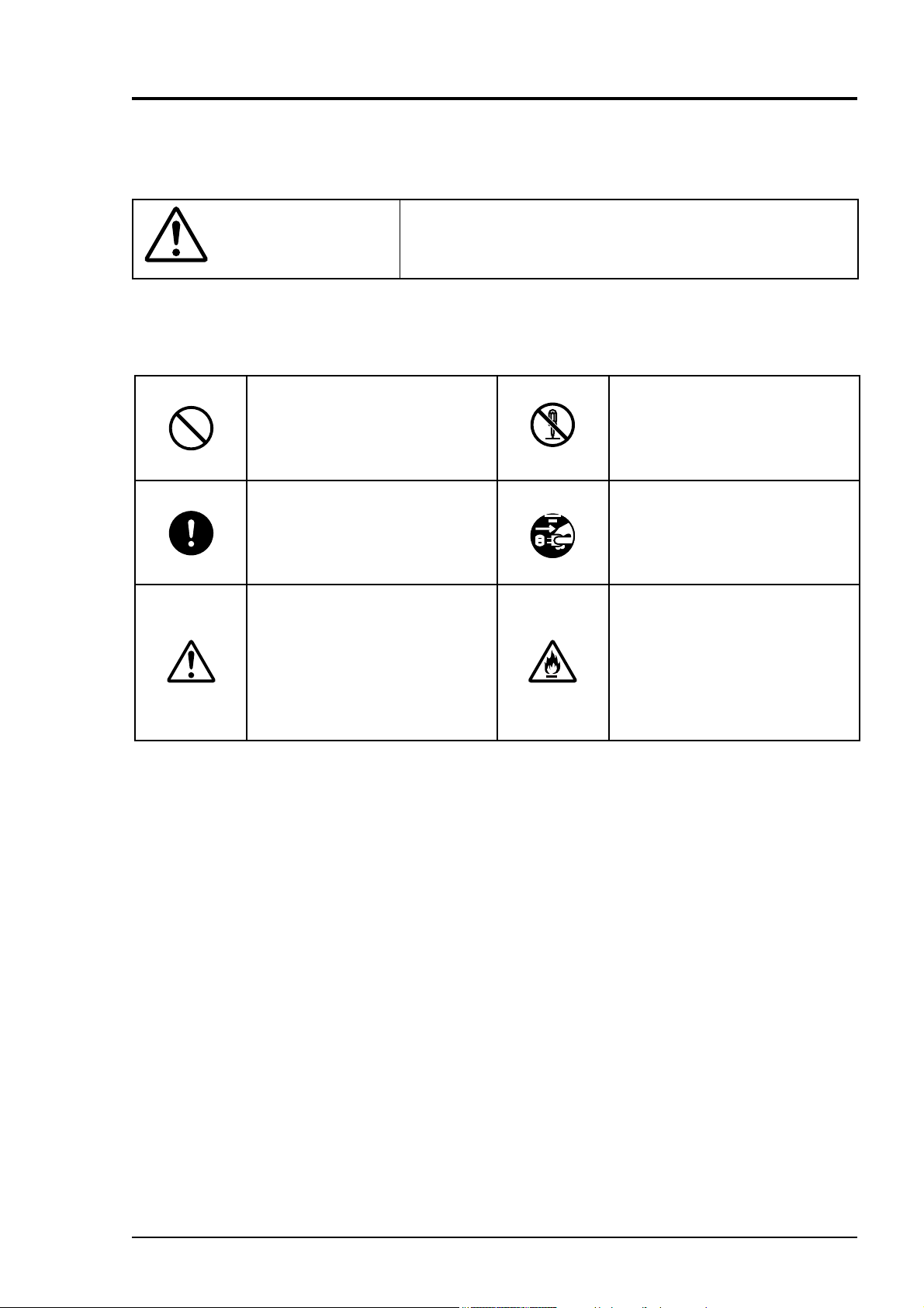
WARNING SYMBOLS AND THEIR MEANINGS
Be sure to observe the following precautions. They offer important information on safety.
● The degree of injuries or damages resulting from improper handling of this device is indicated
by different symbols.
Improper handling of this device may cause dangerous
CAUTION
● The following symbols describe items to be observed.
situations that result in personal injury or property damage.
The symbol indicates “prohibition”.
The symbol indicates “mandatory”
action to be taken.
The symbol provokes “cautions”.
Do not modify this device.
Be sure to pull out the plug.
Be careful. It may result in fire.
INF-TN1FSC-E v
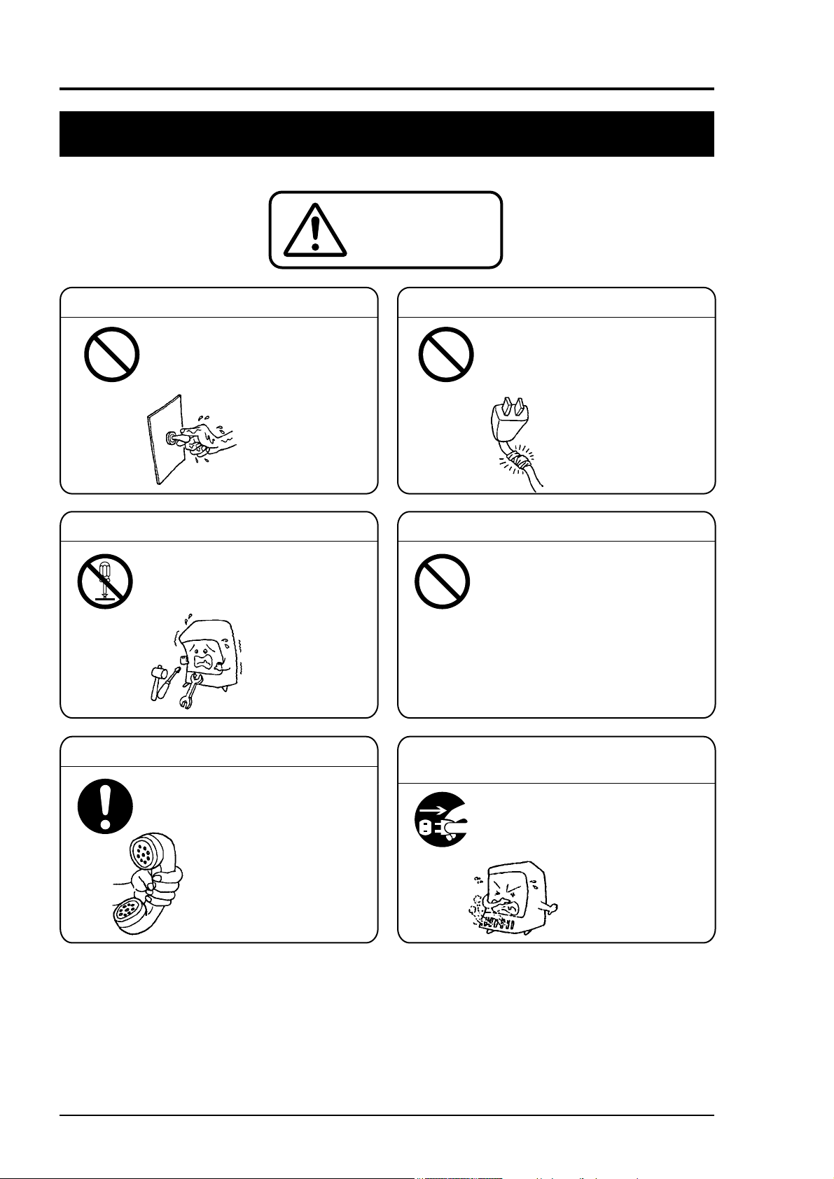
SAFETY PRECAUTIONS
Be sure to read this “Safety Precautions” carefully beforehand for the correct and safe use of this device.
WARNING
Do not touch the switch with a wet hand. Do not break or pull the power cord.
Do not touch the switch
with a wet hand.
Otherwise it may resu lt in
electric shock.
Prohibition
Do not disassemble.
Do n o t disassemble this
device.
Otherwise it may resu lt in an
accident.
Disassemble
is prohibited.
Do not put heavy items
on the power cord.
Do not modify or pull the
power cord.
Prohibition
Otherwise it may break
and result in electric
shock and fire.
Do not use electric parts soaked in water
Replace electric parts or wires
soaked in water due to floods
or some other reasons with
new ones.
Prohibition
Otherwise it may resu lt in
electric shock or fire.
Do not repair.
Pull out the plug immediately in
case of an emergency
Do not use the flammable
gases or volatile agents
such as paint thinner near
the device.
Otherwise it may resu lt
in explosion or fire.
Pull out
the plug
In case of abnormal odor, smoke
or fire is perceived, pull the power
plug immediately.
Ask an authorized
serviceperson or your
dealer for repair.
Otherwise it may
result in electric
shock or fire.
vi INF-TN1FSC-E
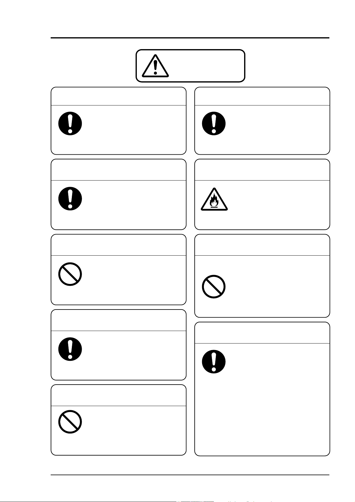
CAUTION
Keep warning labels clean.
Clean or replace the warning
labels so that they can always be
read correctly.
Otherwise it may result in an
accident.
Ask an authorized waste disposal
specialist for disposal.
Do not dispose the device
without proper authorization.
Otherwise it may cause
environmental pollution or result
in an accident.
Do not splash water.
Do not wash or splash water on
the electrical parts inside the
device.
Prohibition
Otherwise it may result in electric
shock.
Be careful when carrying the device.
When carrying the device,
exercise care to avoid physical
shock or vibration.
Otherwise it may cause failure.
For connecting the cable,
turn the power off.
For connecting cable to terminal
of the middle size detector
(Type: FLD410), or the large size
Prohibition
detector (Type: FLD510), turn
the power off.
Inspect the power plug periodically.
Inspect the power plug once
every 6 months. Wipe the dust
off the plug and insert it securely.
Otherwise it may result in electric
shock or fire.
Match power capacity
with the device ratings.
Be sure to connect the device to
the power soruce of proper
voltage and current rating.
Fire hazard
Otherwise it may result in fire.
Use an exclusive power adapter
and built-in battery.
Do not use a power adapter or
built-in Lithium ion battery that is
not exclusive to the main unit.
Otherwise it may break and
cause failure.
• Ambient temperature:
Prohibition
Charge time; 0 to +40°C
In use; –20 to +60°C
Storage time; –20 to +50°C
Use the device in
favorable environment.
Do not use the device in an
environment subjected to dust
or corrosive gases.
Otherwise it may cause failure.
Flow transmitter
• Ambient temperature:
–10 to +55°C (Without printer)
–10 to +45°C (Witt printer)
• Ambient humidity: 90% RH or less
Detector:
• Ambient temperature: –20 to +60°C
• Ambient humidity:
Large/middle size detector; 100% RH or less
Others; 90% RH or less
INF-TN1FSC-E vii
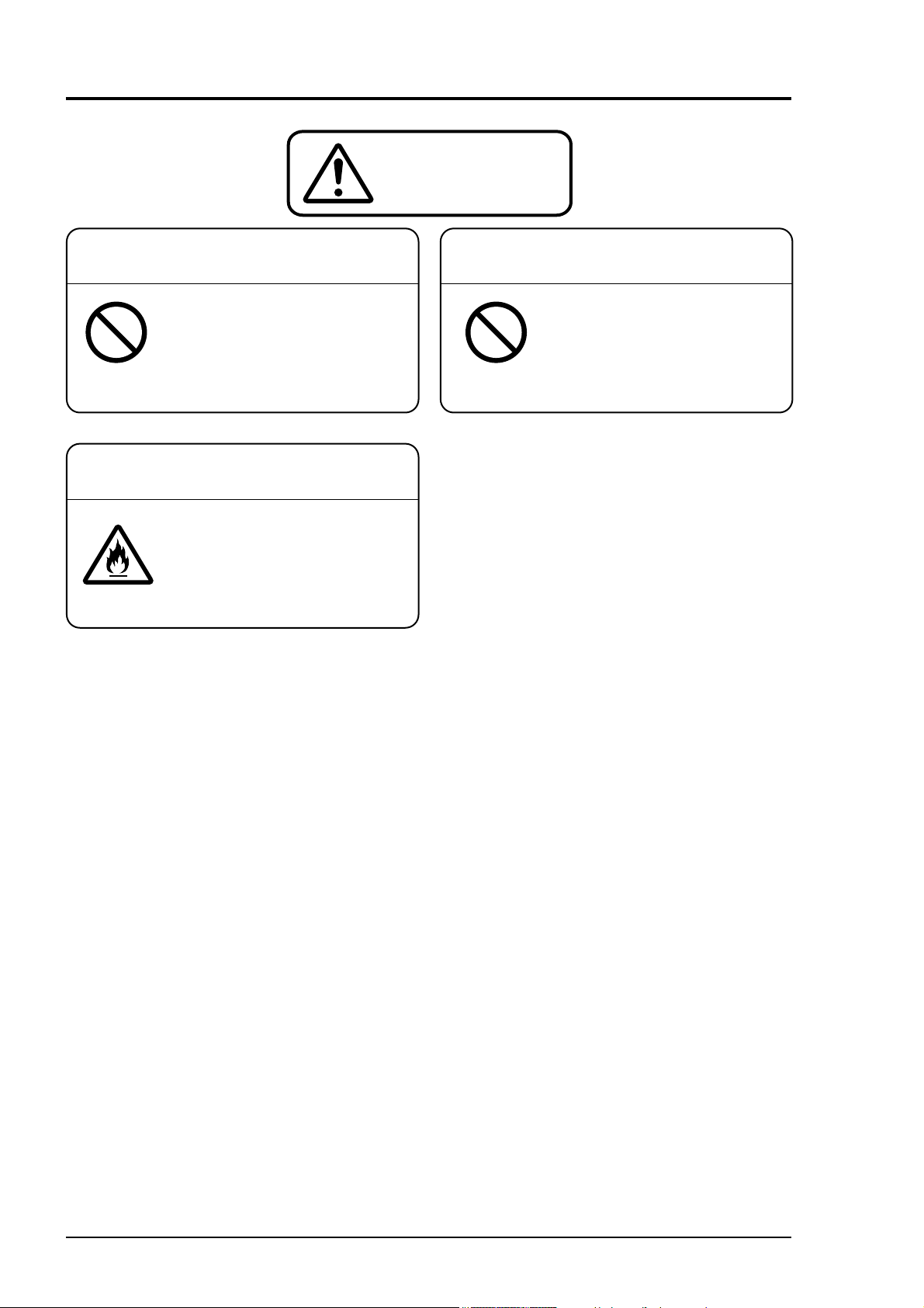
CAUTION
Cause of machine malfunction. Cause of machine malfunction.
Use in a place which is remote
from electrical devices (motor,
transformer, etc.) which generate
Prohibition Prohibition
electromagnetic induction noise,
electrostatic noise, etc.
Fire or damage may result.
Except the main unit (printer, power
adapters, etc.), it is not protectes
for dust or waterproof.
Avoid using the product in a place
where it will be exposed to water or
humidity.
Do not use in a place which is
near cell phones, wireless
devices, etc., which may cause
the machine blunder.
viii INF-TN1FSC-E

1. OVERVIEW
This PORTAFLOW-C is a portable type ultrasonic fl owmeter that allows easy measurement of fl ow rates
in pipes by installing a sensors on the outside of pipes.
A combination of the latest electronics and digital signal processing technologies enables the instrument
to provide a compact and convenient solution to accurately measure system fl ow rates without breaking or
opening the serial transmission and removable memory card functionality allow easy date acquisition and
analysis.
INF-TN1FSC-E 1
2. CHECK OF DELIVERED ITEMS
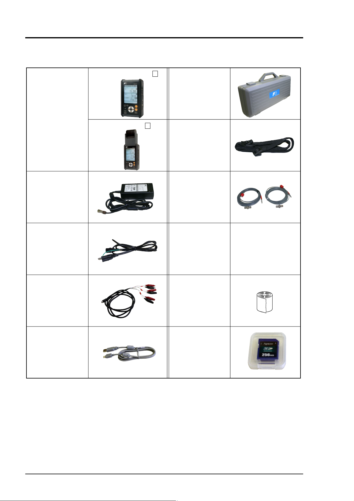
2.1 On purchase of fl ow transmitter (type: FSC)
Without printer (FSC )
Conversion unit Carrying case
With printer (FSC )
AC power supply
adapter
Power connector
conversion cord
Power cord
1
2
Strap
Dedicated signal
cable (5m×2 pcs)
BNC adapter
CD-ROM
Instruction manual
(INF-TN1FSC-E)
Loader Instruction
manual
(INF-TN5A0415-E)
Analog input/
output cord (1.5m)
USB cable (1m)
Roll paper
(When “2” is selected
for the 5th dight.)
SD memory card
(256MB)
(When “1” is selected
for the 9th dight.)
2 INF-TN1FSC-E
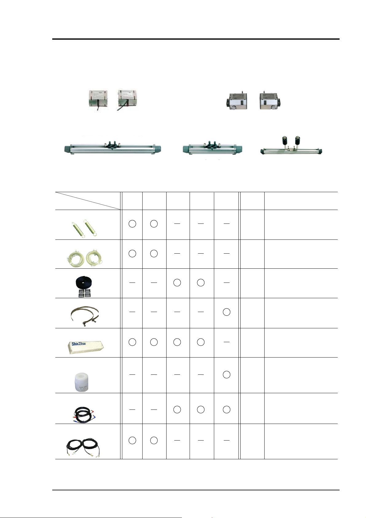
2.2 On purchase of detector (type: FLD)
The following parts are included.
(1) Main unit
Large type (2pcs)
(Type: FLD51)
Small type (standard)
(Type: FLD12)
(2) Accessories
Kind of
detector
• Fastening springs
• φ 2mm wire rope
• Plastic cloth belt
Large
type
Medium
type
Small
type
Small diameter
(Type: FLD22)
Small
diameter
High
tempe-
rature
Medium type (2pcs)
(Type: FLD41)
High-temperature
(Type: FLD32)
Quantity Remarks
2 pcs
2 pcs
1 pc
• Stainless steel belt
• Silicone grease
•
Grease for
high temperature
• Cable for exclusive use
(BNC at both ends)
• Cable for exclusive use
(BNC at one end)
4 pcs
(long)
2 pcs
(short)
1 pc
1 pc
2 pcs
2 pcs
Mfg: Shinetsu
Chemical Industry
Type: G40M (100g)
Mfg: Shinetsu
Chemical Industry
Type: KS62M (100g)
FLD12
FLD22
FLD32
Note) For FLD411 or
FLD511, Mount
the detector.
INF-TN1FSC-E 3
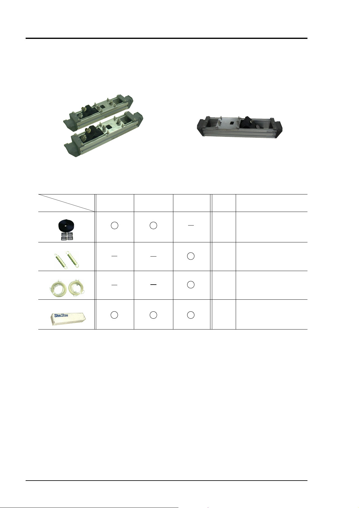
2.3 On purchase of fl ow velocity distribution measurement
detector (type: FSD)
The following parts are included.
(1) Main unit
Small type (Type: FSDP2)
Middle type (Type: FSDP1)
(2) Accessories
Kind of
detector
• Plastic cloth belt
• Fastening springs
• φ 2mm wire rope
• Silicone grease
Large type (Type: FSDP0)
Large typeSmall type Medium type Quantity Remarks
1 pc
2 pcs
2 pcs
Mfg: Shinetsu
1 pc
Type: G40M (100g)
Chemical Industry
4 INF-TN1FSC-E
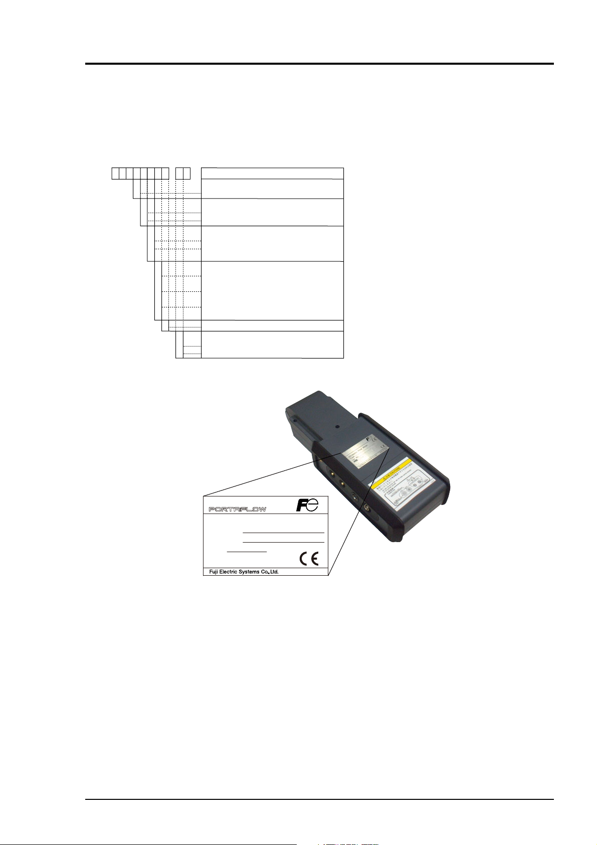
3. CHECK MODEL AND SPECIFICATION
The specifi cation plates attached to the frame of fl ow transmitter and the detector list the type and specifi -
cations of the product.
Check that they represent the type ordered, referring to the following code symbols.
<Flow transmitter: FSC>
12345678-910
10FSC
S
1
2
0
1
A
B
C
1
<Specification>
Standard
<Converter>
Basic system
Basic system + Printer
<Flow velocity profile measurement>
None
Provided (detector to measure flow
velocity profile is separately required.)
<Power adapter>
AC power + power cord (125V AC) for
Japanese and North American use
AC power + power cord (250V AC) for
European and Korean use
AC power + power cord (250V AC) for
Chinese use
Modification No.
<SD memory card>
0
1
None
Provided (256MB)
Description
Ultrasonic Flow Meter
Type FSC
Ser.No.
Mfd.
Charge Unit. Li-ion
TK7N6387
Made in Japan
INF-TN1FSC-E 5
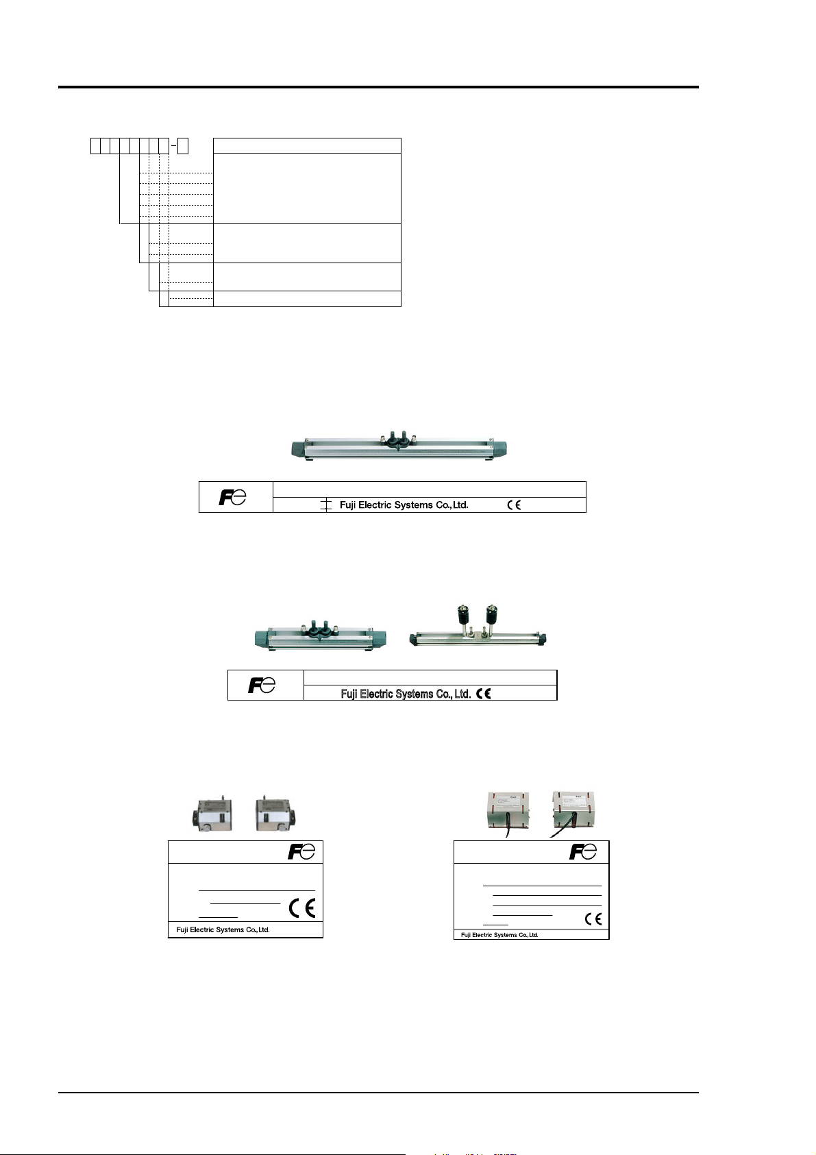
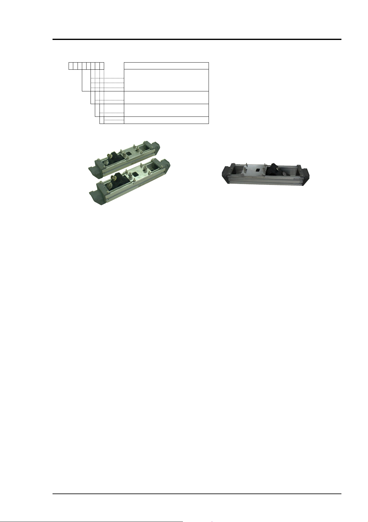
<Detector: FLD>
12345678 9
F
LD A
1
2
2
2
3
2
4
1
5
1
0
1
<Kind>
Small type (for φ50 to φ400mm) Note
Small diameter (for φ13 to φ100mm)
High-temperature (for φ50 to φ400mm) Note
Middle type (for φ200 to φ1200mm)
Large type (for φ200 to φ6000mm)
<Application>
None
Provided (Middle/Large type only)
<Structure>
Y
1
General use
Modification No.
Note)
Use the optional guide rail, if a pipe that does not allow ultrasonic
waves to pass through easily, such as an old pipe, cast iron pipe or a
pipe with mortar lining, or the flow or liquid has high turbidity.
Employ the Z method for mounting.
Applicable diameter range: V method: φ50 to φ250 (FLD32)
Z method: φ150 to φ400 (FLD32, FLD12)
Description
φ50 to φ300 (FLD12)
Ultrasonic Flow Meter
Type
Ser.No.
Mfd.
Type.
Mfd.
Small type (standard)
Type. Ser.No.
Mfd.
Fuji Electric Systems Co., L td.
Small diameter
(Type: FLD22)
Made in Japan
(Type: FLD12)
High-temperature
(Type: FLD32)
Ser.No.
Made in Japan
Ultrasonic Flow Meter
Type
Output
Supply
Ser.No.
Mfd.
Made in Japan
Made in Japan
Medium type (2pcs)
(Type: FLD41)
Large type (2pcs)
(Type: FLD51)
6 INF-TN1FSC-E
<Flow velocity detector: FSDP>
12345678
F
SD 0Y 1
P
2
P
1
P
0
0
Y
1
<Kind>
Small type (F40 to F200mm)
Middle type (F100 to F400mm)
Large type (F200 to F1000mm)
<Application>
None
<Structure>
General use
Modification No.
Description
Small type (Type: FSDP2)
Middle type (Type: FSDP1)
Large type (Type: FSDP0)
INF-TN1FSC-E 7
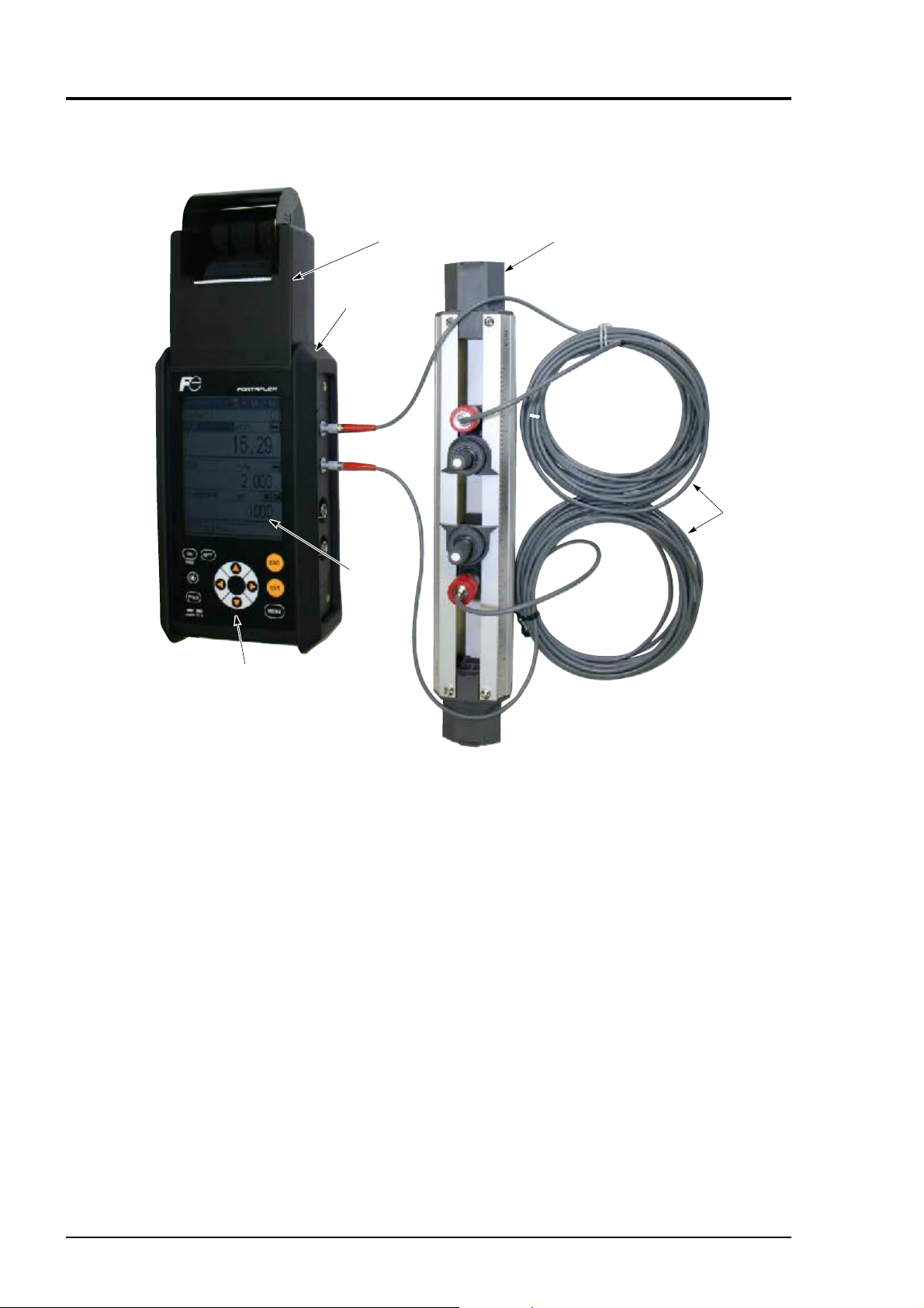
4. NAME AND EXPLANATION OF EACH PART
4.1 Name and explanation of main unit and detector
Keyboard
Rubber
Display
window
Printer
Detector
Dedicoated
signal cable
• Keyboard : Used for turning on/off power supply of the main unit, controlling the
printer, inputting fl uid specifi cations and setting the function of Portafl ow.
• Display window : Displays measured value. Also used for display during programming and
data input.
Because this is a large-size graphic LCD, indications are easy to read.
Even at a dark place, indications can be read by using the backlight.
• Printer (option) : Capable of printing all information of the Portafl ow including print of
display screen capture and printout of measured value.
Portafl ow includes a logger function (for storing measured values in
memory). After storing a few day's data in memory by the logger function,
it may be printed.
Note) Chinese language selection will print Japanese.
• Detector : Attached to a pipe and receives/transmits ultrasonic waves.
• Cable for exclusive use:
Used for transmitting and receiving signals between transmitter and detec-
tors for fl ow measurement.
• Rubber : Protects the main unit from drop impact etc.
8 INF-TN1FSC-E
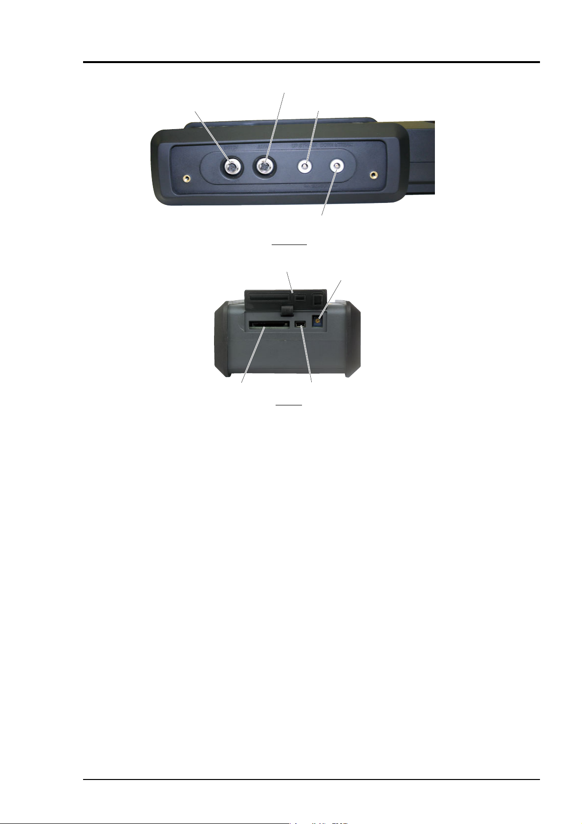
12V DC
(power connector)
AI/AO (4 to 20mA DC analog I/O connector)
UP STREAM
(detector connector on upstream side)
DOWN STREAM
(detector connector on downstream side)
Rightside
SD memory card
Cap
Note
Bottom
USB
LCD contrast
adjusting knob
Note) SD logo is a registered trademark.
• Connectors : 12V DC
Connector of main unit power supply. Inputs 12V DC.
Insert the plug of the power adapter specifi ed for this instrument.
: UP STREAM (upstream side), DOWN STREAM (downstream side)
Receptacles to connect detector cables.
Connect matching the upstream and downstream sides.
: ANALOG IN/OUT
Connect analog input/output signals (4 to 20mA DC).
Analog input signal: 2 points
CH1: 4 to 20mA DC or 1 to 5V DC
CH2: 4 to 20mA DC
Analog output signal: 1 point
4 to 20mA DC
: USB
USB port. Connect to an external system such as personal computer.
: SD memory card
SD card slot. The measurement data and the screen data can be saved.
: Contrast adjusting knob
Adjust the LCD contrast.
Note) Be careful not to lose the protective cap attached to power connector and analog input/
output connector.
INF-TN1FSC-E 9
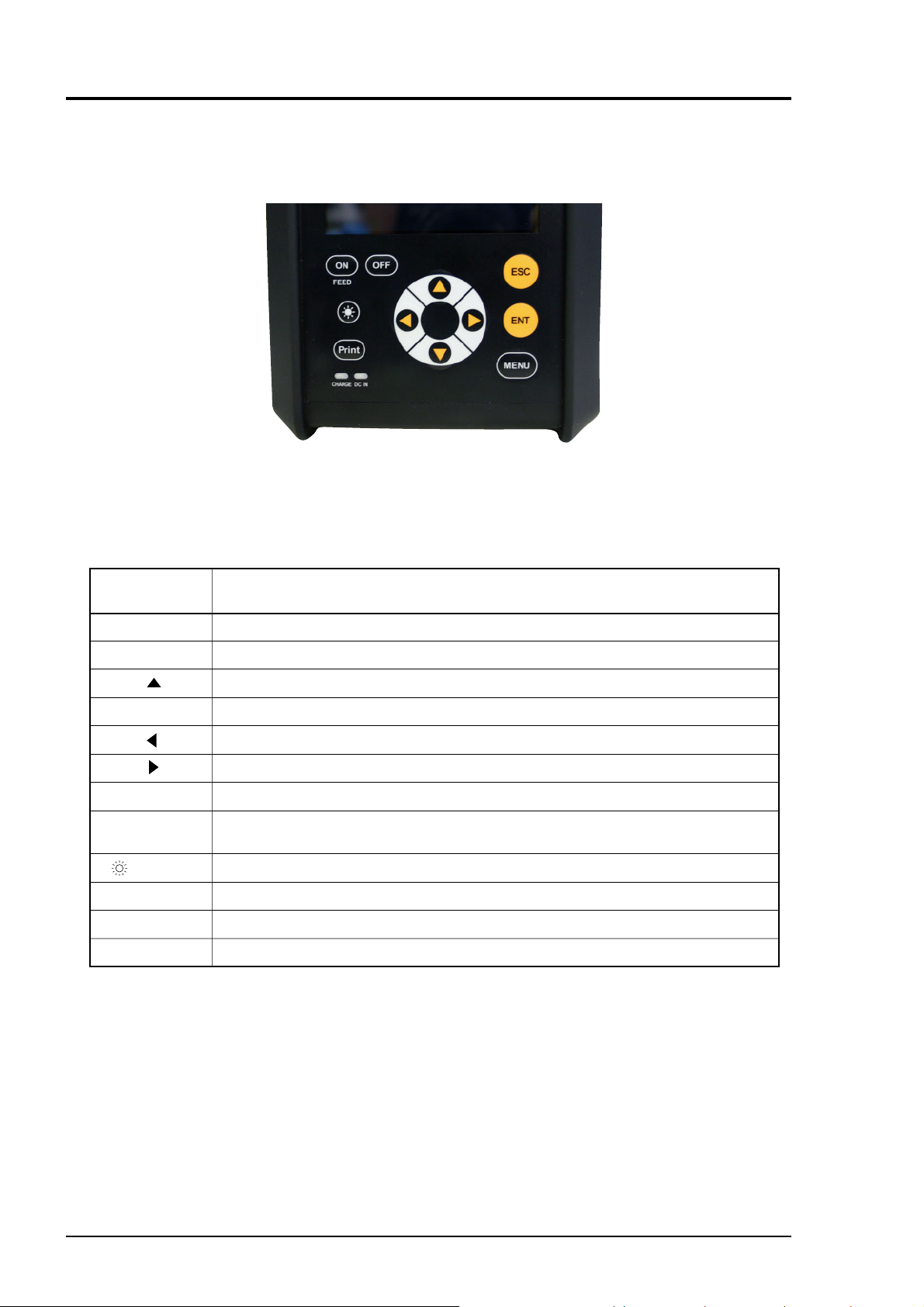
4.2 Explanation of keys
Fig. 3-1 shows the layout of keys and Table 3-1 explains each key.
Table 4-1 Explanation of keys
Fig. 4-1 Layout of keys
Key indication
or lamp
ENT
ESC
▼
ON/OFF
PRINT
(LIGHT)
FAST CHARGE
DC IN
MENU
Description
The keyed-in data, selected item, etc. will be set by pressing this key.
Cancels any setting.
Moves the cursor upward, increments set value, etc.
Moves the cursor downward, decrements set value, etc. (repeats if held down
Moves the cursor leftward, change scale, etc.
Moves the cursor rightward, change scale, etc.
Turns on/off power supply.
Print of the display screen or save the data to SD memory card.
(outputs a hard copy).
Turns on/off the backlight of display screen.
Turns ON in charge. Turns OFF in fully charged condition.
Turns ON with power cable connected.
Displays MENU screen.
(repeats if held down)
(repeats if held down)
(repeats if held down)
)
10 INF-TN1FSC-E

4.3 Handling of SD memory card
Use an SD memory card for recording measured data, fl ow velocity profi le data and screen data.
The equipment is capable of accommodating an SD memory card of capacity up to 8GB. An
SD memory card of capacity 256MB is provided as an option.
Compatible media
• SD memory card
Speed class: Class2, 4, 6
• SDHC memory card
Speed class: Class4, 6
4.3.1 Precautions for handling of SD memory card
(1) Use an SD memory card or SDHC memory card that has been formatted based on a standard.
(2) Make sure to format the SD memory card or SDHC memory card based on its standard.
(3) Firmly insert the SD memory card (or SDHC memory card; hereinafter the same) in the appro-
priate direction, and assure that it has been properly mounted.
(4) Do not remove the card during data read/write operation. Data may be broken or erased.
It is recommended that data stored on the card is periodically backed up.
Important data is lost if the SD memory card is broken. Make sure to back up the data on the
SD memory card.
4.3.2 Formatting forms
For formatting an SD memory card, use dedicated formatting software the memory card manufacturer provides. Data read/write is not permitted if the card is not property formatted.
Formatting forms
• FAT12: 64MB
• FAT16: 128MB, 256MB, 512MB, 1GB, 2GB
• FAT32: 4GB, 8GB
INF-TN1FSC-E 11
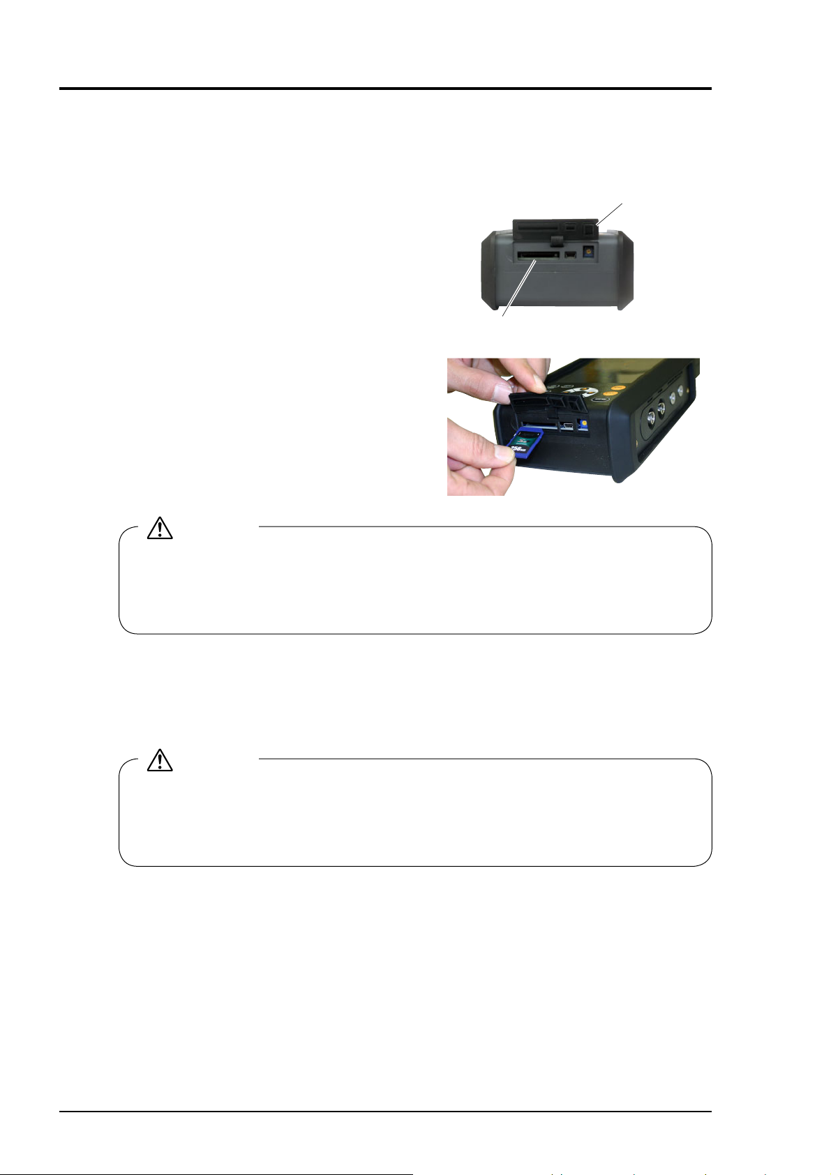
4.3.3 Insertion and removal
Methods for insertion and removal of an SD memory card are described below.
(1) Insertion
Step 1) Open the cap from the main unit bottom
face.
SD memory card slot
Step 2) Insert a memory card into the memory
card slot in the main unit bottom face in
the direction shown on the right.
Card push-in system is adopted for card
mounting. Positively push in the memory
card to the lock-up position.
Cap
CAUTION
When inserting, align the memory card body to match the slot.
Do not insert the card at an angle. Card should slide into slot freely without force. If the
memory card is pushed with force in the state where the card is inserted as tilted, the connector in the main unit will be broken. Be careful.
(2) Removal
Card push-in system is adopted for card mounting. Push the card in straight. The card is unlocked and can be removed.
The data stored on a memory card can be directly read with a PC.
CAUTION
• Do not remove the memory card during data write operation.
• Do not remove the memory card before the main unit identifi es the inserted memory card
after its insertion.
• Be careful with static electricity at the time of removal of the memory card.
12 INF-TN1FSC-E

4.3.4 Data recording to SD memory card
(1) Types of recorded data
Recorded data is of three different types indicated below.
(1) Measured data: One logger fi le is composed of a confi guration fi le and a data fi le.
Confi guration fi le: Records logger start-up time and relevant logger data
Data fi le: Records logging data in a specifi c period produced by logger and
quick logger.
The data fi le is stored as divided by 65,500 lines for permitting
high-speed access and due to restrictions in the maximum number
of lines of CSV display of Microsoft Excel.
(2) Flow velocity plofi le: Records fl ow velocity plofi le data for an hour.
(3) Screen copy: Records screen display copy data
See “10.3.1.(4) DEFINITION OF PRINT KEY”.
(2) File confi guration
Recorded data is stored as fi les on an SD memory card.
The fi le confi guration is such that a folder of site name is located just beneath the root folder and
the following data manipulated by the subject site name is stored beneath said folder.
A folder of site name is created at the time of registration of a site name described in “10.1.1
SITE MEMORY”.
The recorded data is stored in the folder of the site name selected by site selection described in
“10.1.1 SITE MEMORY”.
fi les.
(1) Measured data … Just beneath the folder of site name
Case of logger
• Confi guration data fi le name of created logger: logging name_date_hour.ini
• Data fi le name of created logger: logging name_date_hour.csv
Case of logger
• Confi guration data fi le name of created logger: QUICK_date_hour.ini
• Data fi le name of created logger: QUICK_date_hour.csv
A data fi le can be edited with Excel.
See “16.5.2 Measured data fi le” located toward the end of the volume for the recording
format.
(2) Flow velocity distribution … Beneath VEL folder just beneath folder of site name
• Created flow velocity distribution data file name: Vel_date_hour.csv
A data fi le can be displayed using fl ow velocity distribution demonstrate function of PC
loader software.
See “16.5.3 Flow velocity distribution fi le” located toward the end of the volume for the
recording format.
(3) Screen copy …Beneath DISP folder just beneath folder of site name
• Created screen copy file name: DISP_date_hour.csv
Recording format: Windows Bitmap
INF-TN1FSC-E 13
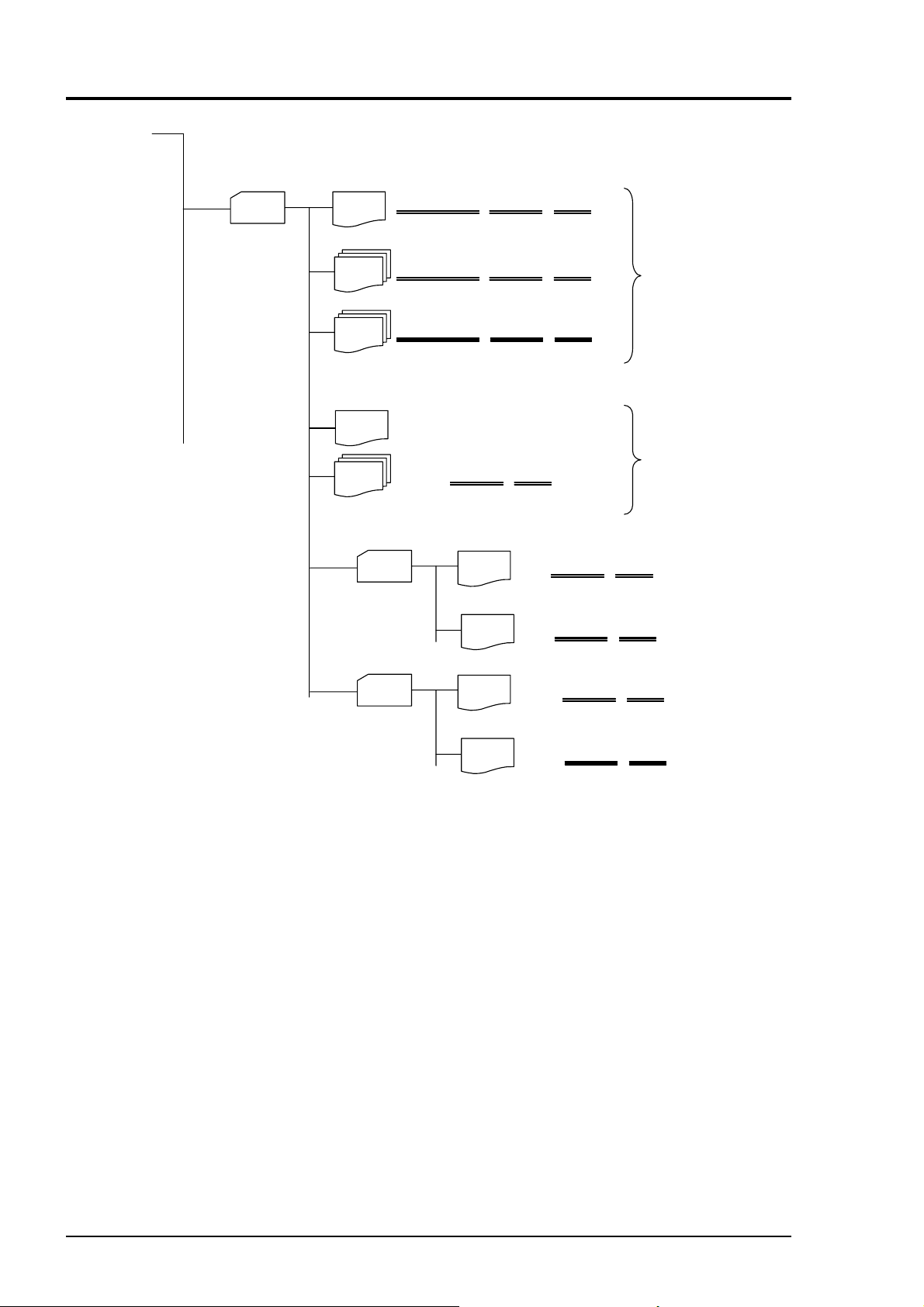
Root
Site name
(Folder)
(File)
(File)
(File)
(File)
(File)
VALVE_Open_20060703_163100.ini
VALVE_Open_20060703_163100.csv
VALVE_Open_20060705_183100.csv
QUICK_20060704_163100.ini
QUICK_20060703_163100.csv
Flow velocity
distribution
VEL
Hard copy
DISP
Log name
Log name
Log name
Date
(File)
(File)
(File)
Date
Date
Date
Time
Time
Time
Time
Vel_20060704_163100.csv
Date
Time
Time
Time
Data
Vel_20060705_163100.csv
Date
DISP_20060704_163100.bmp
Logger
Quicklogger
(File)
Fig. 4-2 File confi guration
DISP_20060705_163100.bmp
Date
Time
14 INF-TN1FSC-E
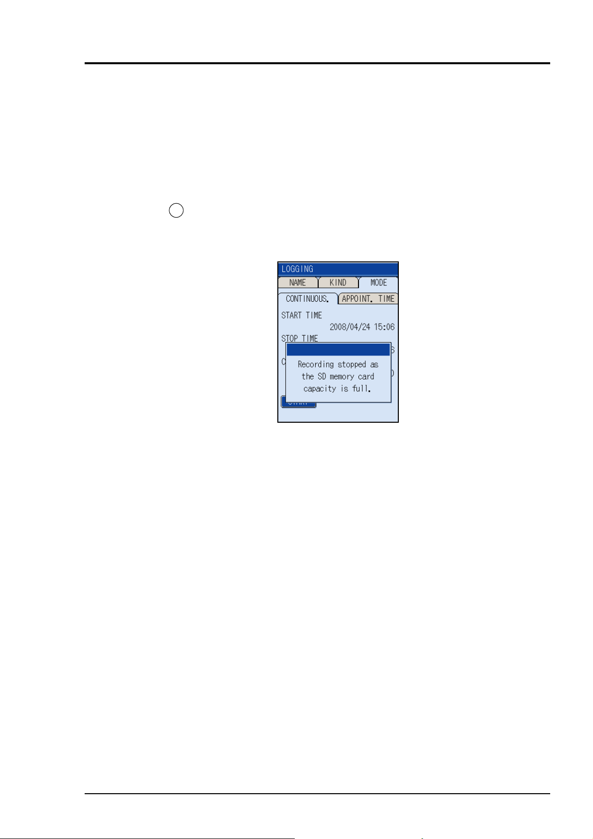
(3) Recording capacity
The recording capacity depends on the capacity of the SD memory card.
One logger fi le is composed of a confi guration fi le and a data fi le.
The data fi le is stored as divided by 65,500 lines for permitting high-speed access and due to
restrictions in the maximum number of lines of CSV display of Microsoft Excel.
The maximum number of data fi les in a logger is 20 fi les in case of a continuous logger, and
is 550 fi les in case of an appointed time logger. If the capacity becomes short during logging
operation, logging operation terminates with the following screen displayed.
Replace the SD memory card immediately, if this screen is displayed.
ESC
Press the
key, or remove the memory card, the message will be cleared.
Note) After reaching the maximum data fi le, the logging will stop.
Recording capacity in case an SD memory card of 256 MB is used with continuous logger
In case where the preservation period is 30 seconds and where logger data of all of 14 types is
stored, it is possible to store measured data for about a year.
In the case stated above, the measured data is divided into 16 fi les, and the capacity of a fi le is
about 15 MB.
See “10.2.1 Setting of data logger function” for the continuous logger and appointed time logger.
See “16.5.1 Types of measured data to be logged” for logger data types.
INF-TN1FSC-E 15
5. POWER ON AND POWER OFF
5.1 Operating power supply
There are two methods available for energizing this instrument; by the built-in battery or with
the power adapter.
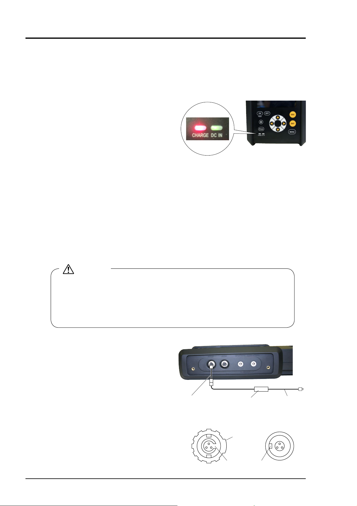
(1) Energizing with built-in battery
(1) To charge the battery
Turn OFF the instrument power and
connect the AC power adapter. The
“CHARGE” LED is lighted in red, and
“DC IN” LED is lighted in green.
When the instrument is fully charged,
"CHARGE” LED goes out.
* About 3 hours will be required for charging..
* In the fully charged condition, the instrument can measure for about 12 hours.
(On condition that the display backlight is turned off and the printer is unused Do not use
current output. the ambient temperature is near normal temperature (20°C).)
Note) The charging time of the built-in battery is 0 to +40°C. If the charging is operated beyond
that range, that will cause fever, leak, performance deterioration, short-life battery.
(2) To energize by built-in battery
When turning on the power supply without connecting the power adapter, the instrument
will be energized by the built-in battery.
Before use, the battery should be fully charged.
(2) Energizing by power adapter
CAUTION
• Use the exclusive power adapter only. Don’t use other adapters, or it may result in
an accident.
• Except the main unit (printer, power adapters, etc.), it is not protectes for dust or
waterproof.
Avoid using the product in a place where it will be exposed to water or humidity.
• AC power adapter
(1) Connect the power connector conversion
mode to the output plug for AC power
adaptor. (The products have already
been connected.)
(2) Connect the plug of the power connector
conversion mode to the 12V DC connector of the main unit. Inserts joining the
connected projection to the cutout, turns
the sleeve lock.
(3) Insert the input plug of this adapter into
the power receptacle.
This adapter has an input voltage range
of 90 to 264V AC (at 50/60Hz).
(4) Insert the input plug of AC adapter into
the outlet.
Power connector
conversion cord
Cord side connector Flow transmitter side
AC power supply
adapter
Sleeve
ProjectionCutout
Power cord
connector
16 INF-TN1FSC-E
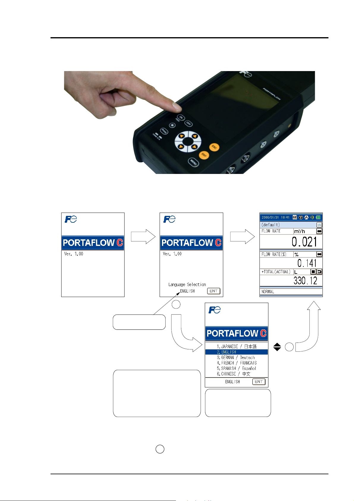
5.2 Turning on the power and language preference
(1) Press the ON switch of the main unit to turn ON the power.
(2) Turn ON the power, and the following
screen appears.
ENT
Language to be set is
displayed.
(3) If there is nothing you can do on
the screen for about 5 sec. the
“MEASURE” screen appears.
ENT
To select the language
When the language is displayed (for about
5 sec.), press the ENT key, and
the “Language Selection”screen appears.
In the screen that is displayed, select
your desired language and press the ENT
key. It returns to the “MEASUREMENT”
screen.
Note:
From the next step, the
language you selected can
be used.
Note1) Select any of 6 languages (Japanese, English, German, French, Spanish, and Chinese).
Note2) To return to the “Language Selection” screen from the “MEASUREMENT” screen in
display, turn OFF the power once and then turn it ON again. In the initial screen that is
displayed, press the
INF-TN1FSC-E 17
ENT
key.
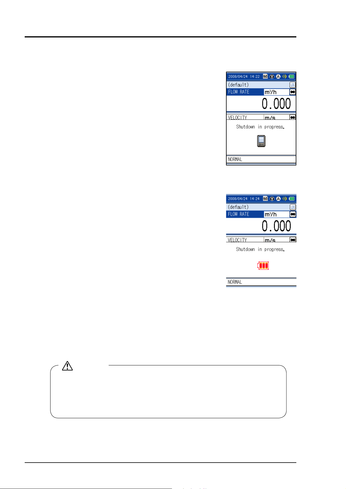
5.3 Power OFF
(1) Power OFF by [OFF] switch
Keep pressing the [OFF] switch on the main unit for 3 seconds or
longer, to turn OFF the power.
In case where measured data is being logged to an SD memory
card, execute logging interrupt processing before turning OFF the
power.
(2) Power OFF caused by drop in capacity of built-in battery
If the fl owmeter is operated by the internal buttery, the power is
turned off after a shut down message appears when the buttery
runs down.
In case where measured data is being logged to an SD memory
card, execute logging interrupt processing before turning OFF the
power.
(3) Precautions for parameter setup change
When parameter setup is changed, parameters are stored in the internal non-volatile memory at
upon return to the measurement screen.
The stored parameters are held even when the power is turned OFF.
Caution: If the power is turned OFF without returning to the measurement screen after parameter setup changes, the parameters are not stored, and setup is required again.
CAUTION
Do not operate the main unit using an AC power adaptor in the state where the builtin battery is removed from the main unit.
• If the power cable is disconnected from the power outlet or if power failure arises
while measured data is being logged to the SD memory card, the data written to
the SD memory card may be broken.
18 INF-TN1FSC-E
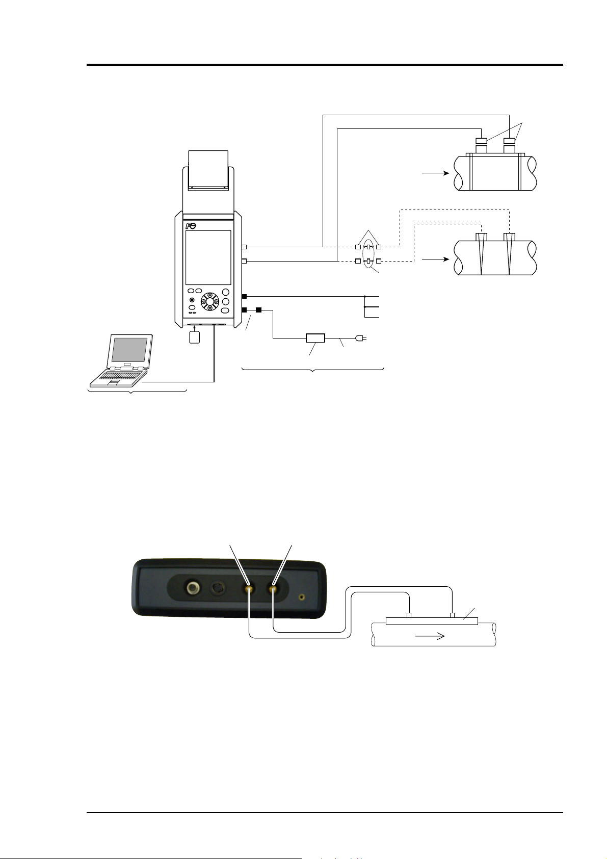
6. WIRING
6.1 Diagram
Printer
(option)
To connect signal cables for FLD12, FLD22, FLD32, FSDP2, FSDP1, FSDP0
BNC
Exclusive use signal cable
To connect signal cables for FLD41 FLD51
connector
Detector
BNC connector
Power cord
Flow
transmitter
PC
USB cable
To connect PC
ON
OFF
FEED
Print
CHARGE DC IN
SD
SD memory
card
PORTAFLOW
Sensor input
(the downstream side)
Sensor input
(the upstream side)
ESC
ENT
MENU
Power connector
Conversion cord
Analog input/output cable
AC power adaptor
for use AC adaptor
6.2 Connection of dedicated cables
This cable is used for connecting the detector to the main unit.
(1) Connect dedicated cables to the upstream and downstream sides of the detector.
(2) Connect one cable connected to the upstream side of the detector to the “UP STREAM”
connector of the main unit, and connect the other cable connected to the down stream side
of the detector to the “DOWN STREAM” connector.
Signal cable
BNC adaptor
AO analog output 4 to 20mA DC
AICH1 analog input 4 to 20mA DC or 1 to 5 V DC
AICH2 analog input 4 to 20mA DC
AC90 to 264V
Detector
DOWN STREAMUP STREAM
Detector
Upstream Downstream
Flow direction
INF-TN1FSC-E 19
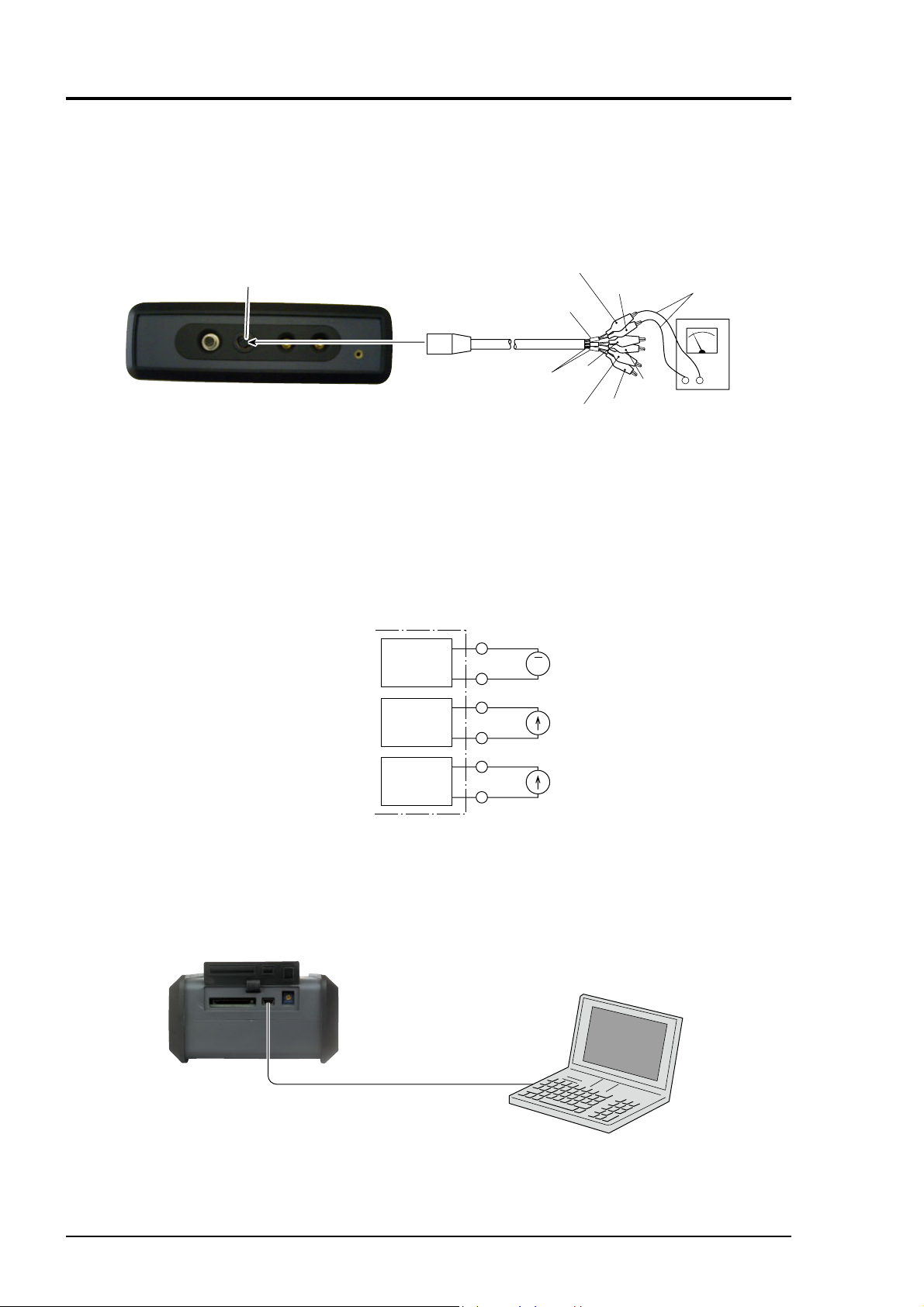
6.3 Connection of analog input/output cable (4 to 20 mA DC)
This cable is used for connection of receiving instruments (indicators, recorders, etc.) and fl ow
transmitter to the main unit. Analog I/O cable is connected as shown below. The cable end is
treated with a clip.
(output)
AI
(input)
Red (+)
AO
Red
(+)
Red
(+)
Black (−)
AO
AIch1
AIch2
Black
(−)
Black
(−)
4 to 20mA
−
+
Indicator,
recorder,
controller, etc.
AI/AO
Note) Plug the
connector
into AI/AO.
(1) Connect clips of the analog I/O cable to the (+) and (−) sides of the receiving instruments,
respectively.
(2) Connect the analog I/O cable to the “AI/AO” connector at the side panel of the main unit.
Note) Allowable load resistance of analog output should be adjusted to 600Ω or less.
Input resistance of analog input is 200Ω.
Converter
AO
AI CH1
Red
Black
Red
Black
+
A
−
AI CH2
6.4 Connection of USB cable
When PC software is used, open the cap of down face of the main unit and USB port of PC;
transmit connecting “USB” port with USB cable.
For PC software, refer to Chapter 12.
Maximum 3m
Mini USB cable
Red
Black
20 INF-TN1FSC-E
7. INPUT OF PIPING SPECIFICATIONS
Before installing the detector, set the specifi cations of a pipe in the main unit to allow measurements.
Caution) Measurements cannot be accomplished without these settings.
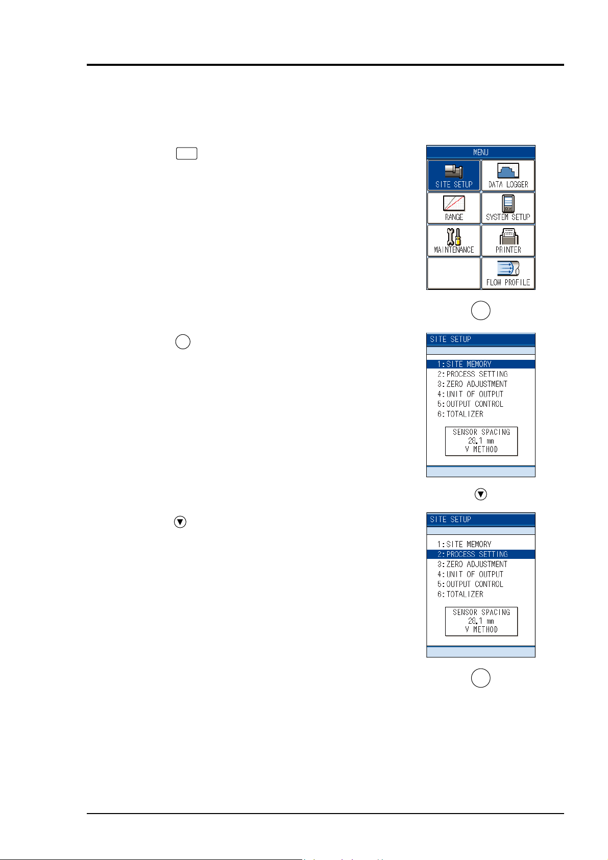
7.1 Display of pipe setup screen
(1) Press the
display the “MENU” screen.
(2) Check that the “SITE SETUP” is reversed from
white to blue.
MENU
key on the “MEASURE” screen to
ENT
(3) Press the
ENT
key, and the “SITE SETUP” screen
is displayed.
(4) Press the key, and move the cursor to “2: PRO-
CESS SETTING”.
ENT
INF-TN1FSC-E 21

(5) Pressing the
ENT
key returns to the “PROCESS
SETTING” screen.
(6) Outline of PIPE PARAMETER (Parameter → Page No. for reference)
Sets lining material → P30
Sets external dimensions of pipe → P27
Sets pipe material → P28
Sets pipe thickness → P31
Sets lining thickness → P29
Sets type of sensor → P35
Set kind of fluid → P32
Sets transmission voltage → P36
Sets sensor mounting method → P34
22 INF-TN1FSC-E
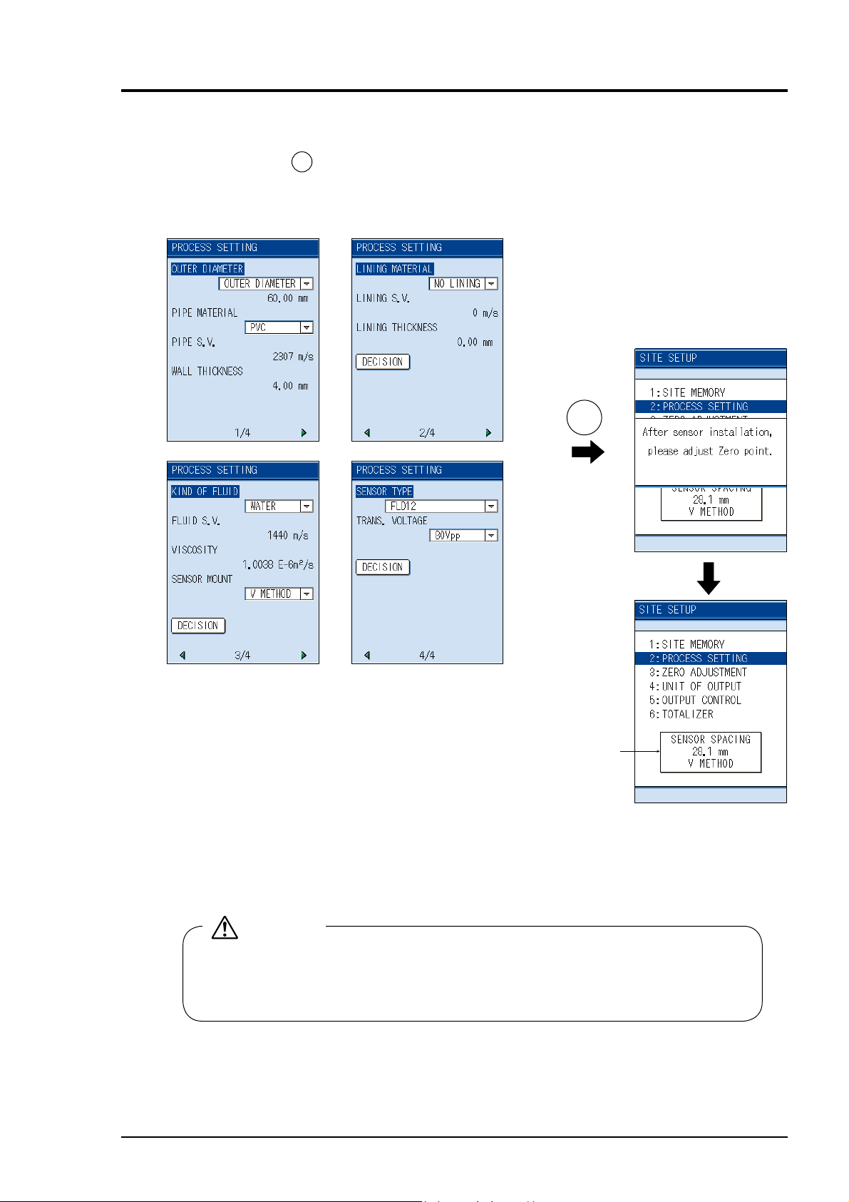
(7) Display of mounting dimensions
After you fi nish the site setting on establish site screen, “Decision” is reversed from white to
ENT
blue by pressing
key.
Display the message “After sensor installation, please adjust Zero point”, turn back to “SITE
SETUP” screen.
At the last line the “SENSOR SPACING” value is displayed.
ENT
Mounting
dimension
Install the sensor according to chapter 8. MOUNTING OF DETECTOR and the mounting
dimension is as displayed on the last line.
CAUTION
• For small pipe diameter, the sensor mounting length can be 0.0mm.
• When the sensor mounting length is 0.0mm, error of the measurement is approximately ±2 to 5%.
INF-TN1FSC-E 23

7.2 Entry of site name (not required measurement)
Enter the name of the site (where measurement is
performed). This name is registered with process
setting ((4) of page 21).
(1) Move the cursor to “1: SITE MEMORY” on the
SITE SETUP screen.
Note) Before setting the “2. Establish setting”,
the Site registration is required.
ENT
ENT
(2) Press the
screen.
key to display the SITE MEMORY
(3) Press the
ENT
key after checking that cursor is
placed in the MODE.
(4) When the mode selection screen appears, move
the cursor to the “REGISTRATION” and press the
ENT
key.
ENT
ENT
24 INF-TN1FSC-E
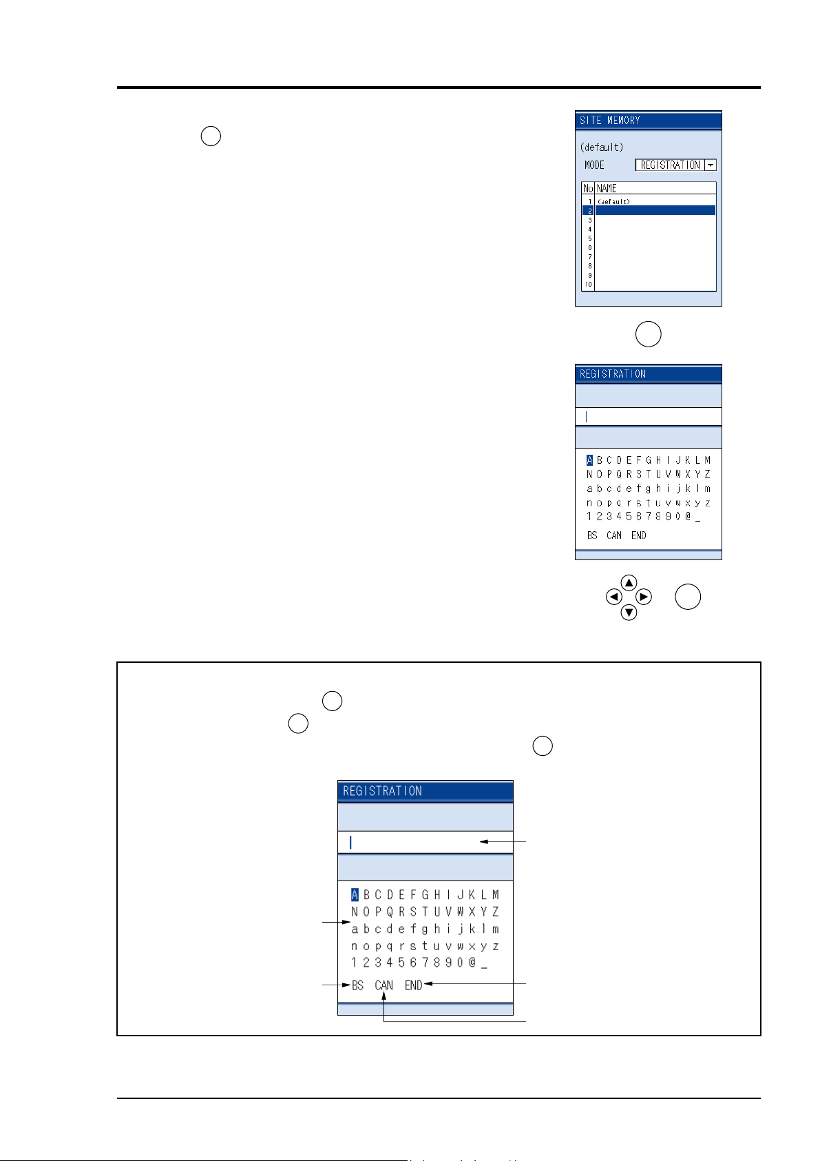
(5) Move the cursor to the unregistered fi eld and press
ENT
the
key.
(6) When the entering screen appears, enter the name
of the site.
Up to 10 characters can be entered.
(See the following for the method of entering.)
ENT
[Reference] Description of character entry screen
ENT
Select a character and press the
Select “BS” and press the
ENT
key. Characters will be displayed one by one in the entry fi eld.
key to delete characters one by one.
In case of stoping entry in the middle, select “CAN” and press the
SITE MEMORY screen.
Character display
Key for deleting a character
in the entry field
ENT
ENT
key to return to the original
Character entry field
Key for registering characters
in the entry field
Cancel key for character entry.
INF-TN1FSC-E 25

(7) Move the cursor to “END” and press the
ENT
key
to complete the character entry.
When moving the cursor in the character entry fi eld
ESC
Press the
key so that the cursor “ | ” will change to
“ █”.
The cursor can be moved by the and the key.
For entering characters to the place the cursor is
moved, press the
ESC
key
The cursor moves to the character entry fi eld.
Note 1) Entry can be made with alphanumeric characters.
Note 2) To stop character entry in the middle, select “CAN” and press the
The original SITE MEMORY screen reappears.
ENT
key.
26 INF-TN1FSC-E

7.3 Outer diameter of piping (unit: mm) (range: 13 to 6000 mm)
The “OUTER DIAMETER” is reversed from
white to blue, on the “PROCESS SETTING”
screen
ENT
Press the
ETER” for selecting the input method of outer
diameter measurement and “CIRCUMFERENCE”
screen will appear.
Press the
outer dimension.
key, the screen of “OUTER DIAM-
ENT
key after the selection to enter the
Use the
or key to cause the digit to move in
the right and left direction
Use the
After entry, press the
or key to enter the numeric.
ENT
key.
Note) Enter outer dimensions, not nominal
diameter (example: 20A → 20).
Outer diameter of piping Perimeter of piping
Outer
diameter
Perimeter
ENT
ENT
ENT
Example) When the outer diameter of piping is 318.5 mm:
ENT ENT
INF-TN1FSC-E 27

7.4 Piping material
Press the key on the “PIPE MATERIAL” is
reversed from white to blue.
ENT
Press the
screen will appear.
key, and the “PIPE MATERIAL”
ENT
key.
or key.
Select the material by the
After entry, press the
When “OTHERS” is selected:
Enter the sound velocity (range: 1000 to 3700m/
s). See page 163, Table (28).
Example) When the piping material is cast iron:
ENT
ENT
ENT
28 INF-TN1FSC-E

7.5 Wall thickness (unit: mm) (range: 0.1 to 100.00mm)
Press the key, the “WALL THICKNESS” is
reversed from white to blue.
ENT
Press the
(See pages 156 to 162, Piping Data ).
Use the
and right.
Using the
entry, press the
Lining and wall thickness of piping
If the wall thickness is not known, measure
it by the wall thickness gauge, and enter the
value.
key, Wall thickness can be entered
or key to move the digit to the left
or key, enter the numeral. After
ENT
key.
B
A
ENT
B : Lining
thickness
A : Wall
thickness
Example) When the wall thickness is 1.25 mm:
ENT
ENT
INF-TN1FSC-E 29

7.6 Lining material
Press the key, “LINING MATERIAL” is reversed from white to blue.
ENT
Press the
screen will appear.
key, the “LINING MATERIAL”
Select the material, using the
ENT
selection, press the
When “OTHERS” is selected:
key.
or key. After
Enter the sound velocity (range 1000 to 3700m/s).
See page 163, Table (28).
Example) When the lining material is mortar:
ENT
ENT
ENT
30 INF-TN1FSC-E

7.7 Lining thickness (unit: mm) (range: 0.01 to 100.00 mm)
When the lining material is set to items other than
“None” in 7.6 Lining material.
Press the
reversed from white to blue.
Press the
can be performed.
The cursor can shift the numeric digit by the
key. The numeric can be entered by the or
key.
After entry, press the
key, the “LINING THICKNESS” is
ENT
key, lining thickness numeric entry
ENT
key.
or
ENT
Example) When the lining thickness is 1.25 mm:
ENT
ENT
INF-TN1FSC-E 31

7.8 Kind of fl uid
Jump to 3/4 page with or key.
Select kind of fl uid.
For fl uid having no entry, enter sound velocity.
(Range: 500 to 2500 m/s)
Press the
reversed from white to blue.
Press the
ID” screen.
or key, the “KIND OF FLUID” is
ENT
key to display the “KIND OF FLU-
Select the kind of fl uid by the
After selection, press the
When “OTHERS” is selected:
ENT
or key.
key.
Enter sound velocity. See page 163, Table (27)
and (29).
ENT
ENT
32 INF-TN1FSC-E
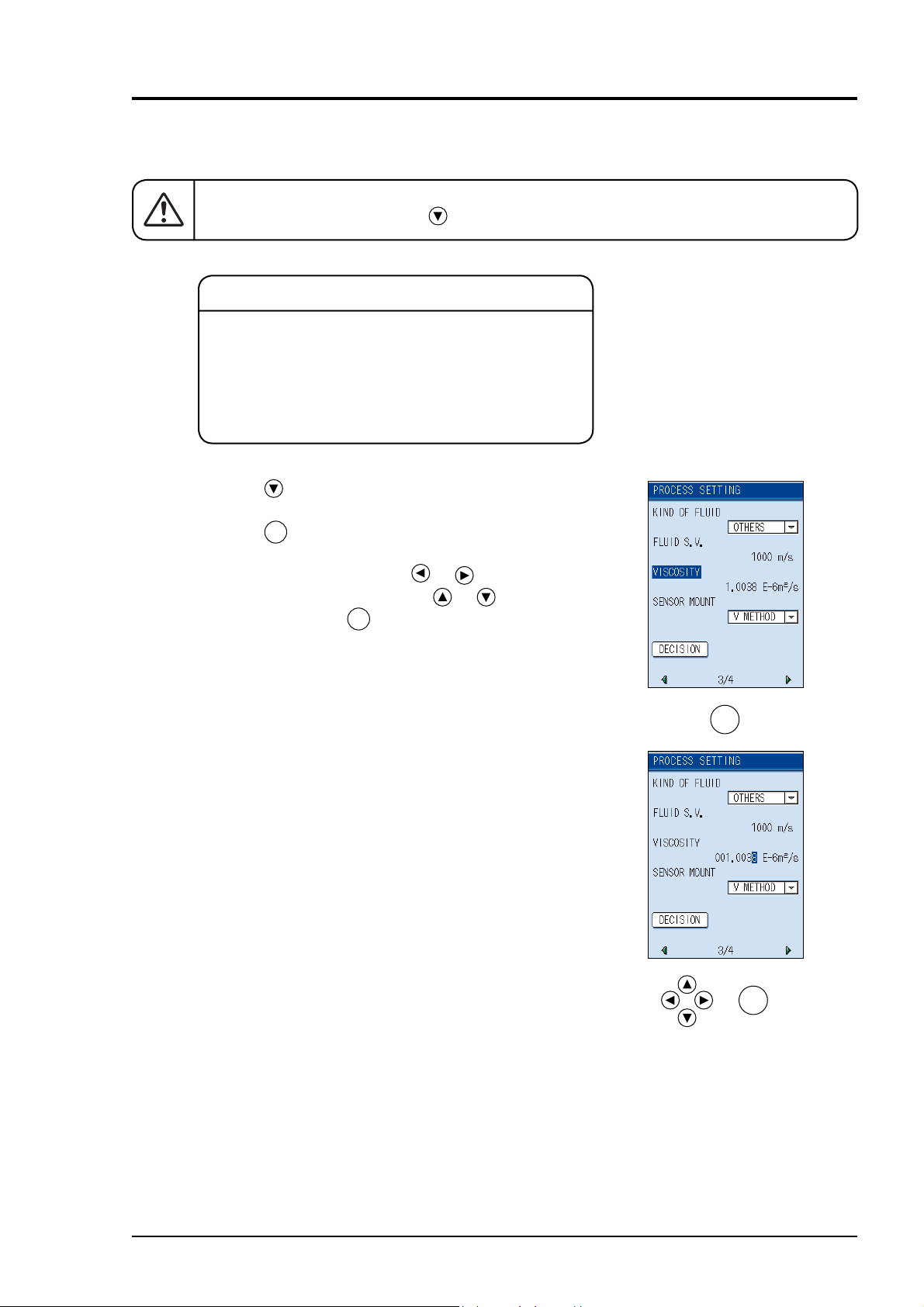
7.9 Viscosity
There is no need to change “1.0038E-6m2/s” when measuring water.
Return the screen by pressing the key.
Remarks
Dynamic viscosity coeffi cient is set to water (20°C).
When measuring accurately or measuring fl uid other
than water, enter as needed.
(See page 163, Table (29).)
(Range: 0.001 × 10
−6
to 999.999 × 10⁻⁶m2/s)
Press the
key, the “VISCOSITY” is reversed
from white to blue.
ENT
Press the
key, you can enter the dynamic viscosity coeffi cient.
Move the digit by pressing the
enter numeric values by using the
ENT
After entry, press the
key.
or key and
or key.
ENT
ENT
INF-TN1FSC-E 33

7.10 Selection of sensor mounting method
Mounting methods available for the sensor are
V method and Z method as illustrated.
To select the mounting method;
Press the
key, the “SENSOR MOUNT” is
reversed from white to blue.
ENT
Press the
key. The “SENSOR MOUNT”
screen will appear.
V method
Z method
(Except.
Small sensor FLD22.)
Select either V or Z method by the
or
key.
Remarks
Select the V method generally. Use the Z method in
the following cases:
• Ample space is not provided.
• High turbidity
• Weak receiving waveform
• Thick scale is deposited on the pipe internal surface.
ENT
ENT
34 INF-TN1FSC-E
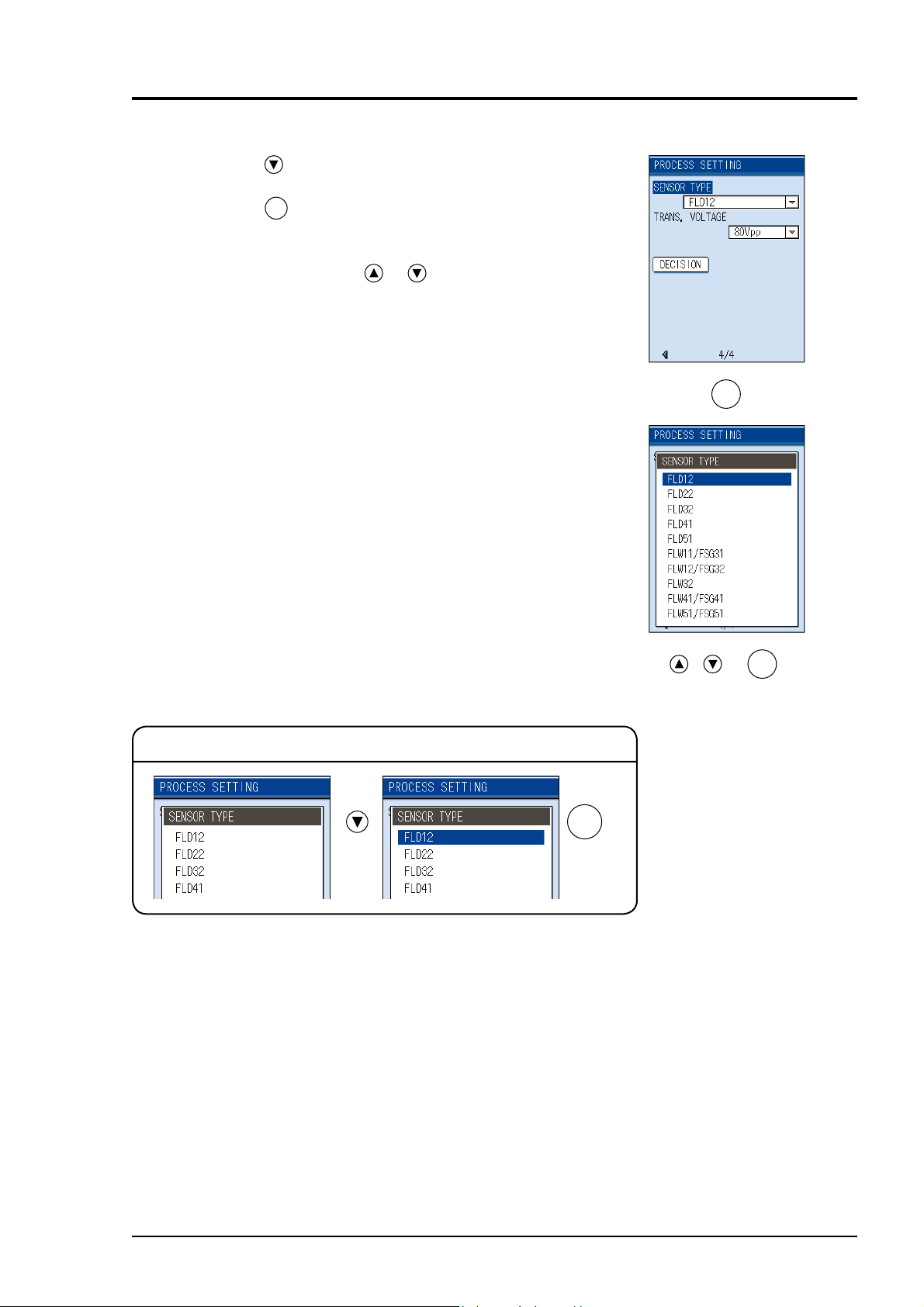
7.11 Kind of sensor
Press the key, “SENSOR TYPE” is reversed
from white to blue.
ENT
Press the
Select any sensor from the type code of sensor to
be used.
Select the sensor by the
key to display the sensor type.
or key.
ENT
Example) When kind of sensor is FLD 12:
ENT
ENT
INF-TN1FSC-E 35

7.12 Transmission voltage (used when an indicator is 1 or less during measurement)
Press the key, the “TRANS. VOLTAGE” is
reversed from white to blue.
ENT
Press the
selection of the transmission voltage level.
Use the
Select “40Vpp” or “80Vpp” generally.
If the indicator cannot be set to MAX with
the level at “160Vpp”, ultrasonic wave
may be attenuated due to contamination or
scales deposited on the piping external and
internal surfaces. Change measurement
location.
Example) When transmission voltage is
key, the screen is ready to allow the
or key to select the level.
ENT
set to “160Vpp”:
ENT
The indicator will be updated on the mea-
surement screen only.
If less than 2 indicators (intensity of receiving
waveform) are displayed on the measurement
screen, raise the transmission voltage.
ENT
Indicator
36 INF-TN1FSC-E

7.13 Completion of PROCESS SETTING
After the settings are completed, press the key
“DECISION” is reversed from white to blue.
ENT
Pressing the
returns to the “SITE SETUP” screen.
After mounting the sensor, perform zero point
calibration.
key to complete settings, and then
ENT
MENU MENU
Note) When the inner mounting diameter is 13mm, the sensor mounting method is 0.0mm or less de-
pending on the pipe materials.
[Unit: mm]
Necessary pipe thickness for fl uid water
CARBON STELL 2.15 FRP 3.21
STAINLESS STEEL 1.87 DUCTILE IRON 2.15
PVC 3.69 PEEK 3.69
COPPER 3.82 PVDF 3.69
CAST IRON 2.98 ACRYLIC 2.90
ALUMINUM 1.99 PP 3.69
When the sensor mounting length is 0.0mm or less, error of the measurement is approximately ±2
to 5%.
INF-TN1FSC-E 37

8. MOUNTING OF DETECTOR
8.1 Selection of mounting location
Detector mounting location, i.e., the conditions of the pipe subjected to fl ow rate measurement
exert a great infl uence on measurement accuracy. So select a location meeting the conditions
listed below.
(1) There is a straight pipe portion of 10D or more on the upstream side and that of 5D or more on
the downstream side.
(2) No factors to disturb the fl ow (such as pump and valve) within about 30D on the upstream side.
Classification For upstream side For downstream side
L ≥ 5D
90° bend
Te e
Diffuser
Reducer
More than 10D
More than
More than
10D
0.5D
More than
10D
≥ 1.5D
L ≥ 10D
Detector
L ≥ 50D
L ≥ 30D
D
L ≥ 10D
L ≥ 10D
L ≥ 5D
L ≥ 5D
Valves
Pump
L ≥ 30D
Flow control valve exists on upstream side.
Stop valve
Check valve
Flow control valve exists on downstream side.
L ≥ 50D
L ≥ 10D
P
Extracted from Japan Electric and Machinery Industry Society (JEMIS-032)
38 INF-TN1FSC-E

(3) Pipe is always fi lled with fl uid. Neither air bubbles nor foreign materials are contained in the
fl uid.
(4) There is an ample maintenance space around the pipe to which the detector is to be mounted
(see fi gure below).
Note 1) Secure an adequate space for allowing a person to stand and work on both sides of a
pipe.
Note 2) D indicates the inside diameter of a pipe.
200
or more
Not e
2000 or more
200
or more
D + 1200 or more
600
or more
D
600
or more
D : Pipe diameter
Space required for mounting detector
(5) The piping must completely be fi lled with fl uid when it fl ows.
Air-collecting
Pipe may
not be filled
with liquid.
Pump
Pipe may not be filled with liquid.
Good
Good
(6) For a horizontal pipe, mount the detector within ±45° of the horizontal plane.
For a vertical pipe, the detector can be mounted at any position on the outer circumference.
Air bubbles
Pipe
45°
Horizontal plane
45°
Deposits of
sludge
INF-TN1FSC-E 39

(7) Avoid mounting the detector near a deformation, fl ange or welded part on the pipe.
Welded part Flange or welded Welded part
40 INF-TN1FSC-E

8.2 Selection of detector
(1) Selection of mounting methods
There are 2 methods for mounting the detector; V method and Z method. For the mounting
space, see the following sketch.
<Large/Mediam sensor>
L
Detector
D
V method
<Small diameter sensor, small sensor or high-temperature sensor>
Length of frame of each sensor
L L
V method Z method
Frame
Mounting method
Detector
D
Length of frame of each sensor
L
Z method
L: Mounting dimension
mounting dimension for
sensor displayed on the
SITE SETUP screen
Employ the Z method in the following cases.
• Mounting space need be saved (mounting space of the Z method is about one half of the V
method's).
• Turbid fl uid such as sewage is to be measured.
• Pipe has mortar lining.
• A thick fi lm of scale may have been formed on the inner surface of pipe because it is old.
• In sufi cient received signal-strength with mounting detectors in V method while using maxi-
mum transmission voltage.
INF-TN1FSC-E 41

(2) Image fi gure of mounting dimension
Mounting
method
Mounting
dimensions
V method
Mounting dimensions
FLD41FLD12, 22, 32Type
V method
Mounting dimensions
Type
Mounting
method
Mounting
dimensions
Type
Mounting
method
Mounting
dimensions
FLD51
V method
Mounting dimensions
FLD41 FLD51 FLD12, FLD32
Z method Z method Z method
Mounting
dimensions
Mounting
dimensions
Mounting
dimensions
(3) Detector selection standards
The Z method for large size sensor is recommended for outer diameter 300mm or more.
FLD51 should be used as much as possible for pipes such as old pipes, cast iron pipes, and mortar lining pipes, through which it is diffi cult for ultrasonic signals to pass.
Detector
Type Diameter Temperature
FLD22
FLD12
FLD32
FLD41
FLD51
13 100mm (V method)
50 300mm (V method)
150 400mm (Z method)
50 250mm (V method)
150 400mm (Z method)
200 600mm (V method)
200
200 3000mm (V method)
200
1200mm (Z method)
6000mm
(Z method)
−40 +100°C
−40 +100°C
−40
−40 +80°C
−40 +80°C
+200°C
42 INF-TN1FSC-E

8.3 Use of surface-treated accessories
Eliminate pitting, corrosion, unevenness, etc. with paint thinner and sandpaper from the pipe
portion where the detector is to be mounted.
Note) In case jute is wound on a pipe, it should be peeled off before the above treatment.
When cast iron pipe is used, grind the sensor mounting surface by using a sander for
smoothness.
Detector Width
Small outer
diameter FLD22
Small size
(standard) sensor
FLD12
Medium size sensor
FLD51
Large size sensor
FLD51
High temperature
FLD32
320 mm or more
540 mm or more
Mounting dimension
(L) + 200 mm or more
Mounting dimension
(L) + 200 mm or more
530 mm or more
Jute is wound
Pipe
Width
INF-TN1FSC-E 43

8.4 How to mount small size (standard) sensor and small outer diameter sensor to pipe
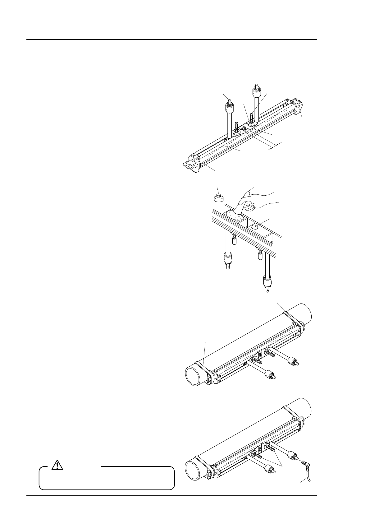
8.4.1 How to mount a sensor (V method)
(1) Loosen the lock nut and slide the sensor so as to
meet the mounting dimension and then tighten
the nut.
(2) Apply a coat of silicone grease to the transmit-
ting surface of the sensor. Spread the compound
over the entire area.
Keep the sensor retracted by turning the element
holder counterclockwise.
After cleaning the surface of the pipe, the sensor
should be mounted
CAUTION
Apply a small quantity (like toothpaste) of
silicon grease to the transmitter unit.
Saddle
Lock nut
Element holdder
BNC connector
Cursor
Mounting
dimension (L)
Scale
Frame
Transmitter unit
Element holder
(3) Fix the both ends (saddles) of the sensor to the
pipe by cloth belts.
Mounting will be facilitated by winding the
cloth belts on the pipe in advance.
Cloth belts are usable at 80°C or lower. If beyond 80°C, stainless steel belts should be used.
(High-temperature stainless belt: Drawing No.
TK7G7981C1)
(4) Make sure the sensor is mounted in parallel with
the pipe axis and the mounting dimension is
right. Then, turn the element holder clockwise
until the sensor comes in close contact with the
pipe.
Stop turning the element holder when it stiffens
because the transmitting surface comes in contact with the pipe surface. Be careful not to turn
the holder excessively.
Cloth belt
Cable
Element holder
44 INF-TN1FSC-E

8.4.2 How to mount a small size (standard) sensor (Z method)
(1) Remove saddle set screws at 4 loca-
tions, and remove a saddle and a sensor unit out of the frame.
Also, remove a saddle on the guide rail
for small size sensor (option).
(2) Mount the removed sensor unit on the
guide rail for small size sensor.
Fasten the sensor unit with mounting
dimension (L).
Saddle
Lock nut
Element holder
BNC c onnec t or
Curs er
Scale
Frame
Guide rall for small size sensor
(3) Spread siliocone grease over the whole
transmitting surface of the sensor.
Turn the element holder counterclockwise to return the sensor.
After cleaning the surface of the pipe,
the sensor should be mounted.
(4) Mount each sensor individually on the
marking line.
Silicone grease
Element holder
Front view Back view
Upper side of
the marking line
Mounting
dimension (L)
Transmitting surface
Bottom side of
the marking line
INF-TN1FSC-E 45

(5) Make sure that the sensor is mounted in paral-
lel with the piping and that the mounting position is correct. Then, turn the element holder
clockwise until the sensor is fi rmly fi tted to the
piping.
Stop turning the element holder where the
transmitting surface contacts the surface of
pipe, and thus the element holder will not
rotate.
Do not turn it excessively.
Cable
Element holder
46 INF-TN1FSC-E

8.5 How to mount large and medium size sensor
8.5.1 How to determine mounting position
Determine the mounting position by carrying out the following work.
For this work, gauge paper is necessary (For the gauge paper, refer to page 57).
(1) Match the edge of gauge paper with the line at
about 100mm from one end of the pipe portion
treated for detector mounting, and wind the
gauge paper so that the line marked on the paper
is parallel with the pipe axis (fi x with tape not to
allow deviation). At this time, the edge of gauge
paper should be aligned.
(2) Extending the line marked on the gauge paper,
mark straight line A on the pipe.
(3) Mark a line along on edge of the gauge paper.
The intersection of this line and straight line A is
replaced with A
.
0
(4) In mounting by the V method, peel the gauge
paper and measure the mounting dimension
from A
to determine A2 position. At this posi-
0
tion, mark a line orthogonal to the straight line
A.
Line drawn
on gauge paper
Draw line A.
Draw a line
along the edge.
200mm
100mm
Align this edge.
A0
A0A2
and A2 become the mounting positions.
A
0
Example) L = 200mm
(5) In mounting by the Z method, measure the
circumference from A
with a measuring tape.
0
At 1/2 of the circumference, determine points B
, and mark a line (straight line B) con-
and B
1
necting those points.
(6) Mark the points B0 and peel off the gauge paper.
Measure the mounting dimension from B
0
to
determine B2 position. At this position, make a
line orthogonal to the straight line B.
and B2 become the mounting positions.
A
0
Example) L = 100mm
0
B1 B0
B2
A0A1
Straight line B
100mm
B0
B0
A0, A1B0, B1
A0
B2
INF-TN1FSC-E 47

8.5.2 How to connect medium size sensor for FLD410 type only
(1) Remove the sensor cover.
CAUTION
Be careful not to cut your hands or etc. by
the cover.
(2) Mount the sensors so that the upstream and
downstream sensors can be distinguished from
each other.
Remove the cable clamp.
Note) In case of removing the cable clamp, be
sure not to lose the nut.
Cover
Driver
Cable
clamp
Cable
clamp
Nut
(3) Insert the coaxial cable through the cable lead-in
port.
Coaxial cable
loosen the terminal screws (G, +).
Connect core line white to (+), shield wire to
(G).
Note) At this time, remove the resistor.
CAUTION
For connecting coaxial cable to terminal,
turn the power off,.
48 INF-TN1FSC-E

(4) Secure the coaxial cable with the cable clamp.
(5) Put the cover on the detector.
Cable clamp
INF-TN1FSC-E 49

8.5.3 How to connect large size sensor for FLD510 type only
(1) Slide the detector cover slightly. Remove the
cover with a driver.
(2) Determine the mounting position of sensor on
the pipe.
Align the transmission direction marks.
(3) Put a mark on the inlet of coaxial cable.
When the pipe is horizontally installed with the
detector, allow the coaxial cable to be suspended
to prevent entry of water from the cable inlet.
When the pipe is installed vertically, it does not
matter how the coaxial cable should be installed.
Cover
Transmission direction mark
Transmission direction mark
Note) Upstream and downstream sensors
should be able to be identifi ed.
(4) Connect the coaxial cable to terminal (G, +) and
fi x it with the cable clamp.
Connect core line white to (+), shield wire to
(G).
(5) Install the cover.
CAUTION
• Be careful not to cut your hands or etc. by the cover.
• For connecting coaxial cable to terminal, turn the power off.
Cable retainer
Rubber bushing
50 INF-TN1FSC-E
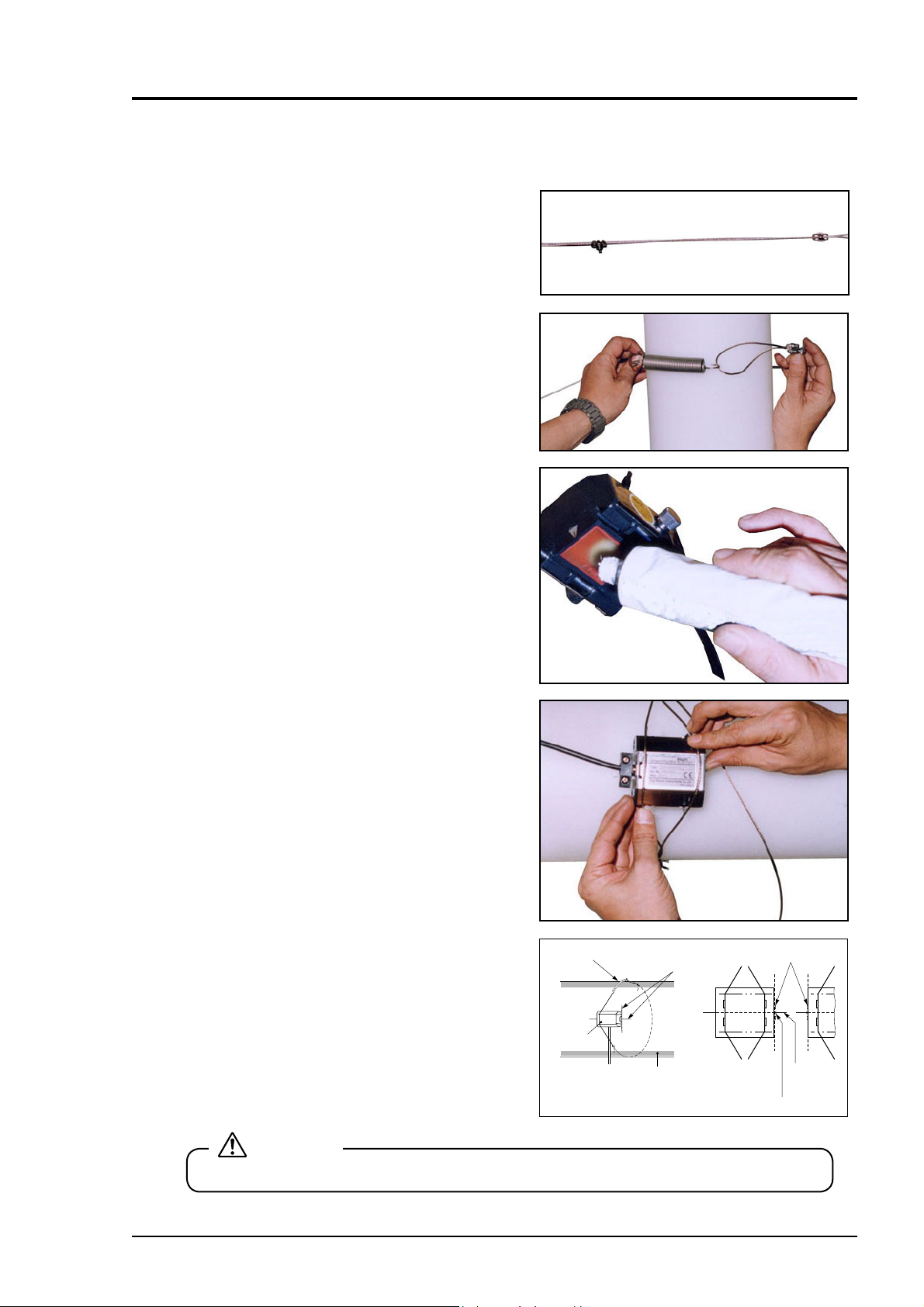
8.5.4 Mounting of medium type sensor on pipe
Mounting the detector using the following procedure.
(1) Provide wire rope for the upstream and the
downstream detectors.
Make sure that the length of the wire rope is
longer than the circumference of the pipe.
(2) Lay the wire rope around the pipe at the position
of the upstream detector.
Then hook the mounting spring into the wire
rope.
(3) Spread silicone fi ller over the whole transmitting
side of the sensor.
Care should be taken to prevent entry of air
bubbles.
(4) After cleaning the surface of the pipe, the sensor
should be mounted.
(5) Spread the wire rope near the marked lines in
the left-right direction, bring the sensor in close
contact and fi t the wire rope.
Make sure that the matching mark on the sensor
is aligned with the marking line.
CAUTION
Be careful not to cut your hands or etc. by the wire rope.
Mounting spring
Sensor
Marking line
Pipe
Transmitting mark
Marking
line
Matching mark
INF-TN1FSC-E 51

(6) Make sure that the center mark on the sensor is
aligned with the marking line. Then, connect the
coaxial cable to the transmitter.
Note) Do not pull the coaxial cable.
If it is pulled, the sensor is shifted which
results in incorrect measurements.
Matching mark
Marking line
(7) After mounting the upstream sensor, mount the
downstream sensor in the same way.
The fi gure is for mounting by the Z method.
Cable side
Upstream
side
Transmitting marker side
Downstream
side
Cable sideTransmitting marker side
52 INF-TN1FSC-E
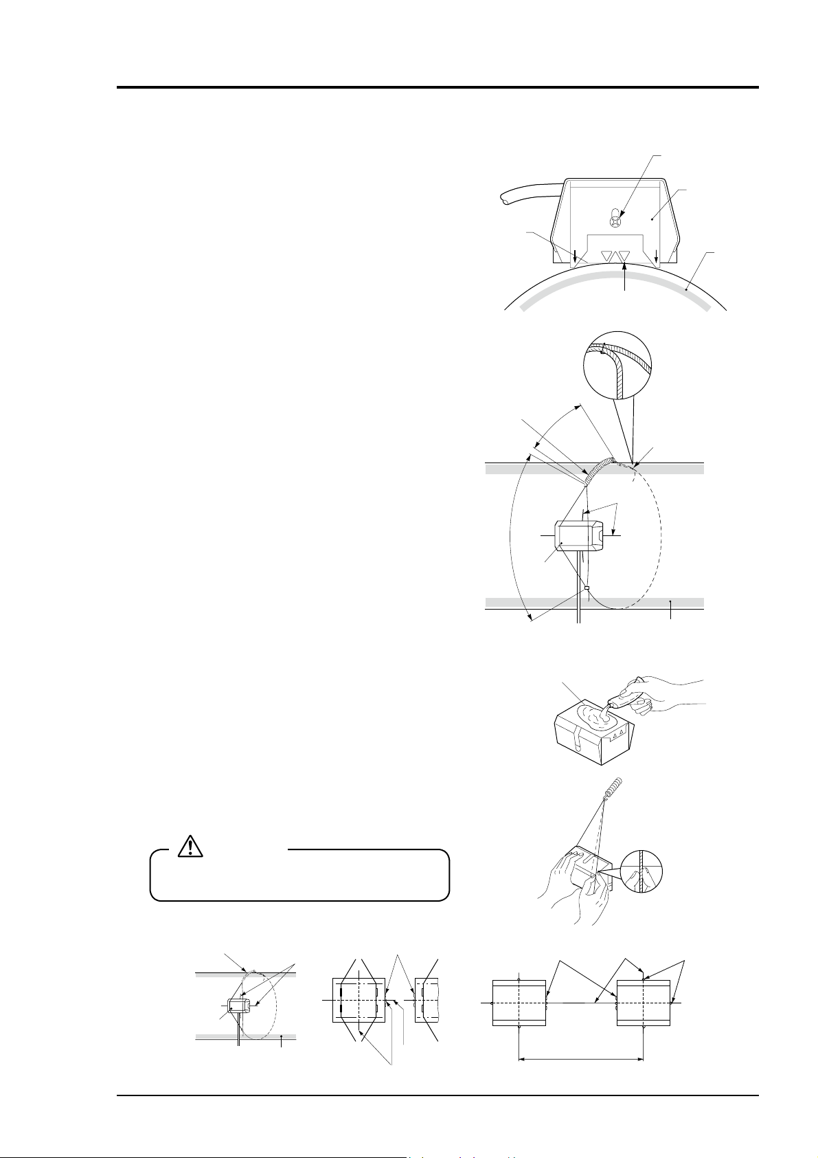
8.5.5 How to mount large size sensor to pipe
(1) Height adjustment of guide plate
• Place the sensor on the pipe surface in parallel
with the pipe axis.
• Loosen the guide plate fi xing screw and slide
the guide plate until its edge and transmitting
surface touch the surface of pipe.
• Then tighten the fi xing screw.
(2) How to determine the length of wire rope
• Place the sensor on the marked lines and fi t the
wire rope and fastening spring.
• Loosen the wire clip and pull the wire rope
until the overall length of fastening spring
approximates 180mm. Then tighten the wire
clip.
(The fastening spring has a free length of
110mm.)
• While fi xing the wire rope, remove the sensor.
(3) Mounting of sensor
• Wipe off contaminates from the transmitting
surface of sensor and the sensor mounting
surface of pipe.
• Apply the silicone grease on the transmitting
surface of sensor wile spreading it evenly.
• Film thickness of the silicone grease should be
about 3mm.
• Spread the wire rope near the marked lines
in the left-right direction, bring the sensor in
close contact and fi t the wire rope.
• Align the matching mark of sensor with the
marked line. In addition, make the transmitting direction marks of sensors face each
other.
• Make sure the matching mark of sensor is
aligned with the marked line and connect the
coaxial cable to the converter.
Transmission
surface
Fastening
spring
600
Sensor
Tramsmitting
180
surface
Fixing screw
Guide plate
Pipe
Transmission
direction mark
Loosen this wire clip
and pull the wire rope.
Marked lines
Pipe
Note) Do not pull the coaxial cable. Other-
wise, the sensor will be activated to
disturb measurement.
CAUTION
Be careful not to cut your hands or etc. by the
wire rope.
Fastening spring
Marked line
Sensor
Pipe
INF-TN1FSC-E 53
Transmission mark
Marked line
Matching mark
Transmission
mark
dimension (L)
Marked lline
Mounting
Matching
mark
8.6 How to mount high temperature sensor to pipe
8.6.1 How to mount a sensor (V method)
(1) Loosen the lock nut and slide the sensor so
as to meet the mounting dimension and then
tighten the nut.
(2) Apply a coat of grease for high temperature to
the transmitting surface of the sensor. Spread
the compound over the entire area.
Keep the sensor retracted by turning the element holder counterclockwise.
After cleaning the surface of the pipe, the sensor should be mounted.
BNC connecot
Frame
High temperature
grease
Lock nut
Scale
Element holder
Saddle
Cursor
Mounting
dimension
(L)
Spatula
Transmission
unit
(3) Fix the both ends (saddles) of the sensor to
the pipe by stainless belts.
(4) Make sure the sensor is mounted in parallel
with the pipe axis and the mounting dimension is right. Then, turn the element holder
clockwise until the sensor comes in close
contact with the pipe.
Stop turning the element holder when it stiffens because the transmitting surface comes in
contact with the pipe surface. Be careful not
to turn the holder excessively.
CAUTION
Be careful not to cut your hands or etc. by the
stainless belt.
Stainless belt
Stainless belt
Element
holder
Cable
54 INF-TN1FSC-E
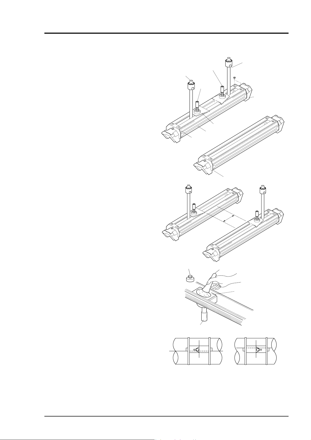
8.6.2 How to mount a sensor (Z method)
(1) Remove saddle set screws at 4 loca-
tions, and remove a saddle and a sensor unit out of the frame.
Also, remove a saddle on the guide rail
for high temperature sensor (option).
(2) Mount the removed sensor unit on the
guide rail for high temperature sensor.
Fasten the sensor unit with mounting
dimension (L).
Lock nut
Sensor unit
BNC connector
Element
holder
Saddle
Cursor
Frame
Scale
Guide rail for high temperature sensor
(3) Spread high-temperature grease over
the whole transmitting surface of the
sensor.
Turn the element holder counterclockwise to return the sensor.
After cleaning the surface of the pipe,
the sensor should be mounted.
(4) Mount each sensor individually on the
marking line.
High temperature
grease
Element holder
Front view Back view
Upper side of
the marking line
Mounting
dimension (L)
Spatula
Transmitting surface
Bottom side of
the marking line
INF-TN1FSC-E 55

(5) Make sure that the sensor is mounted
in parallel with the piping and that the
mounting position is correct. Then,
turn the element holder clockwise until
the sensor is fi rmly fi tted to the piping.
Stop turning the element holder where
the transmitting surface contacts the
surface of pipe, and thus the element
holder will not rotate.
Do not turn it excessively.
Element holder
Cable
56 INF-TN1FSC-E

8.7 How to fold gage paper (used for determining mounting position)
(1) Prepare a sheet of paper (vinyl sheet) of 4 D or
more in length and 200 mm or longer in width
(D is preferable) as shown below.
(2) Draw a line intersecting at right angles with the
longest sides about 100 mm from one paper end.
4D
200 mm or
D or larger
Parallel
About 100 mm
INF-TN1FSC-E 57
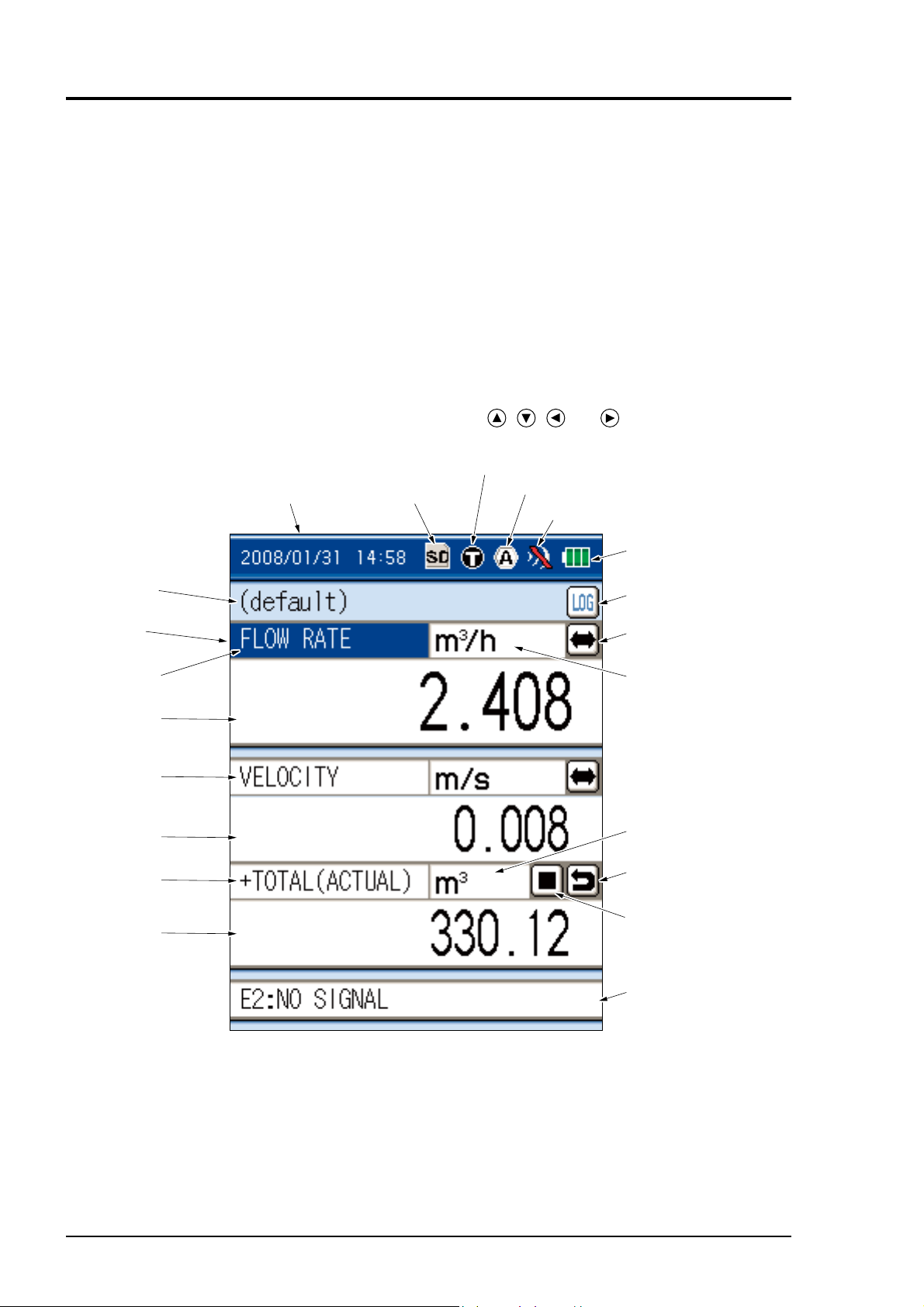
9. START MEASURING
When wiring, piping settings and mounting of the sensor are completed, start the measurement.
The contents displayed on the measurement screen are as follows.
• On the measurement screen, instantaneous fl ow, instantaneous fl ow velocity, integrated fl ow rate,
analog output, and analog input are displayed.
Of the 3 stages displayed on the MEASURE screen, contents can be arbitrarily allocated. Alloca-
tion is accomplished by selection of “measurement kind (fl ow rate, velocity, total, etc.)”.
If the fl ow rate is displayed when water fl ow stops, refer to page 66, “ZERO ADJUSTMENT” and
page 72, “CUT OFF”.
If the fl ow display fl uctuates, refer to page 70, “DAMPING”.
• Integrated fl ow rate value is available in the range from 0000000000 to 9999999999. If the value
exceeds 9999999999, it returns to the preset value.
• Move the cursor on the measurement screen using the
(1) Clock
(2) SD memory card
, , and keys.
(3) Measurement mode
(4) Analog input/output
(5) Indicator
(7) Site name
Curs or
(10) Measure mernt kind
Display 1
(10) Measure mernt kind
Display 2
(10) Measure mernt kind
Display 3
(6) Battery
(8) Quick logger
(13) Switching meas ure ment s cree n
(11) Unit of flow rate
(12) Unit of totalize
(15) Totalize reset
(14) Stat us display of
totalize
(9) Status display
58 INF-TN1FSC-E

(1) Clock
This instrument has a timer function. Refer to “10.3.1(1) Clock” function to set the time.
The timer function should be used based on this clock.
(2) Memory card
Displays the memory card loading status.
: When the memory card is not set.
: When the memory card is set.
: When the memory card is fi lled up
: When the memory card is write protected.
: When the memory card is write-protected and being fi lled up.
(3) Measurement mode
Displays the current measurement mode.
: Measured by the transit time method.
Indication at heat quantity measurement (icon color indicates the status).
• Black: No heat quantity measurement (Example:
• Blue: Heat quantity measurement, cooling operation (Example:
• Red: Heat quantity measurement, heating operation (Example:
)
)
)
For measuring heat fl ow, refer to “10.3.3 CALORIE MODE” function.
(4) Analog input/output
Display the usage state of analog input and output.
For using analog input or output, refer to “10.3.2 analog input/ output” function.
: Analog input/output valid
: Analog input/output invalid
(5) Indicator
Shows the intensity of ultrasonic receiving signal. Displays with 4-level.
If the signal is weak, refer to “7.12 Transmission voltage” and raise the transmission voltage
level.
: With signal (max.)
: With signal
: Signal decay
: Without signal
(6) Battery status
Displays the remaining charge of battery.
For charging the built-in battery, refer to (1) Energizing with built-in battery in “5.1 Operating
power supply”.
: Charged
: Battery level 2
: Battery level 1
: Battery shortage
It is recommended to charge the internal battery.
(7) Site name
Displays the name of the operated site.
INF-TN1FSC-E 59

(8) Quick logger
Logger can be started from the measurement screen. For logger function by timer operation,
refer to “10.2.3 LOGGING”.
Note) It cannot be started during data logging.
: Logger started
: Logger stopped
: Cannot be started
(9) Status display
Displays the current status. In case more than one error is displayed, the
is indicated at the
far right.
Check if “NORMAL” is displayed.If the sensor is not connected, other messages may be displayed. This is not an error.
In case another message is displayed after installing and connecting the sensor, take corrective
actions according to page 140, “10.8 Contents of error in status display”.
If “NORMAL” is not displayed when 1 or less indicator is display, refer to page 147, “12.3 Error in measured value”.
(10) Kind of measurement
When changing the kind of measurement on the
measurement screen:
Flow rate, velocity, total display can be changed
on the measurement screen.
• Move the cursor to the measurement screen to
be changed.
ENT
• Press the
key, and the screen appears,
enabling the kind of measurement to be
selected. Select any kind of measurement by
or key and then press the
the
ENT
key.
(11) Flow rate
When changing the fl ow rate on the measure-
ment screen:
Unit of fl ow rate may be changed on the mea-
surement screen.
• Move the cursor to the unit of fl ow rate to be
changed.
• Pressing
or key, move the cursor to the
unit of fl ow rate you want to change.
ENT
• Press the
key, and the screen appears,
enabling the unit of fl ow rate to be selected.
Select any unit by pressing the or key
ENT
and then press the
key.
(12) Unit of total
When changing the unit of total, refer to “UNIT OF OUTPUT”.
60 INF-TN1FSC-E

(13) Changing decimal position
Decimal place can be changed.
Decimal position can be changed on the measurement screen.
• For modifi cation method, move the cursor
by pressing
or key.
• Move the cursor to the both ends of numeric
by pressing
• Press the
or key (◄000.000►).
ENT
key, the decimal position can
be changed. (The ends of cursor color will
thicken up)
• Pressing or key, select the changing
position, and then press the
ENT
key.
(14) Switching measurement screens
The measurement value screen can be switched to the measurement graph screen.
Move the cursor to the
and press the
ENT
key.
The screen switches as shown below.
Follow the same steps described above to return to the previous measurement value screen.
Changing
decimal
position
ENT
Scale setting can be changed on the measurement graph screen.
Move the cursor to the
Select the item by the
Use the
Pressing the
or key for entering and press the
ESC
key returns to the original status.
and press the
or key and press the
ENT
ENT
ESC
key.
ENT
key to change the setting.
ENT
for setting.
INF-TN1FSC-E 61

(15) Status display of total
It allows you to start/stop the total process on
the “MEASUREMENT” screen.
Refer to “10.1.5 TOTAL” about the totalizing
function by timer operation.
Move the cursor to the
ENT
the
key.
or and press
The total process can be made in the “TOTAL”.
: START: Totalizing in progress
: STOP: Not totalized
(16) Total reset
The total value can be set to 0.
Move the cursor to the
and press the
ENT
key to reset the total value.
Start
62 INF-TN1FSC-E

10. SETTING OPERATION (APPLICATION)
This section describes an outline and page confi guration of each function page.
Various function pages are called up from the menu screen.
MENU
MENU
or
ESC
SITE SETUP RANGE
Condition settings for
measurement
Setting of input and
output range
Various function pages
ENT
[Menu screen][Measure screen]
MENU
ESC
or
DATA LOGGER
Saving of measured value
to memory, and display
and output of data
PRINTER
Various outputs on printer
SYSTEM SETUP MAINTENANCE
Change of basic system
settings of main unit
Check function of
device status
Note) For fl ow velocity distribution within option, refer to “10.7 Flow velocity distribution display func-
tion (option).
INF-TN1FSC-E 63

10.1 How to use SITE SETUP function (SITE SETUP page)
10.1.1 SITE MEMORY: when registering data which are set and calibrated on the page
“SITE MEMORY” allows you to register data which are set and calibrated on the “SITE
SETUP” page to the memory of the main unit.
When measurements are performed repeatedly in the same pipe, registered data can be loaded
to help you in achieving measurements. Up to 32 registrations of data can be made to the
memory.
Registration data: Establish setting, zero point adjustment, unit of output, output control.
[Operation]
(1) Select “SITE MEMORY” by press-
ing the
or key on the “SITE
SETUP” page.
ENT
Press the
key, and the “SITE
MEMORY” screen is displayed.
To return to the “SITE SETUP”
ESC
screen, press the
key.
(2) Move the cursor to “MODE” and press
ENT
the
key. The mode selection screen
will appear.
ENT
When pressing the
key after mode
selection, the relevant mode is determined.
ENT
ESC
Reads out the
contents of setting.
Stores the contents
of setting in memory.
Deletes the contents
of setting.
(3) Select “SELECTION” to read out the
data, “REGISTRATION” to register the data and “DELETE” to delete the data.
64 INF-TN1FSC-E

• For selecting “SELECTION”, select a name of a site by using the cursor and press the
key. So, this function enables you to load the data.
ENT
ENT
ENT
• For selecting “REGISTRATION”, move the cursor to an empty fi eld of NAME and press the
ENT
key. So, this function enables you to register the data you set. Enter the name of the site.
(Refer to “7.2 Entry of site name” for details.)
ENT ENT
• For selecting “DELETE”, select the name of the deleted site by using the cursor and press the
ENT
key. Select “YES” on the screen and press the
ENT
key. So, this function enables you to
delete the data.
Note: Be careful since pressing “YES” deletes the PROCESS SETTING data you registered.
ENT ENT
INF-TN1FSC-E 65
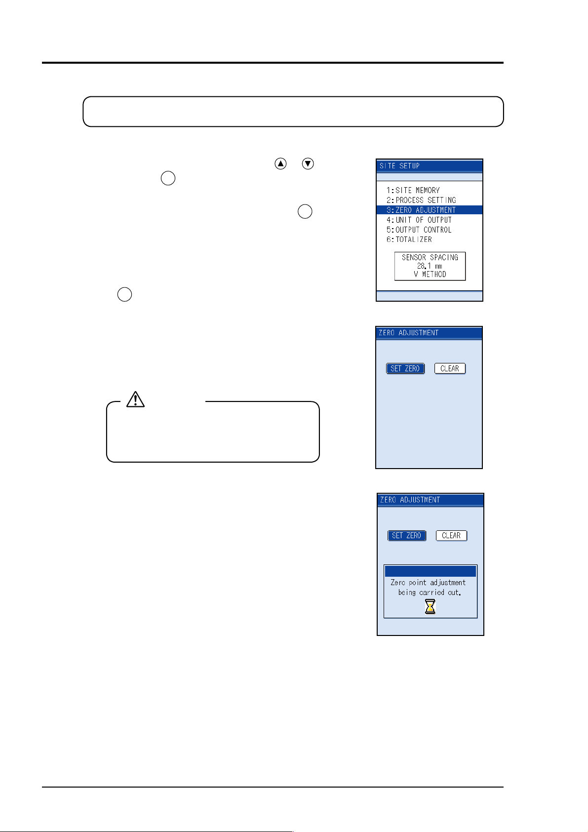
10.1.2 ZERO ADJUSTMENT: when performing zero adjustment
On this screen, zero point is set or cleared.
[Operation]
(1) Select “ZERO ADJUSTMENT” by the
ENT
and press the
key. The zero adjustment screen
or key
will appear.
(2) Select ZERO ADJUSTMENT, and press the
Zero adjustment to be specifi ed is carried out.
• [SET ZERO]
Perform zero adjustment in situation where the fl ow
is stopped.
The measurement indication should be at zero when
ENT
the
key is pressed.
This zero calibration operation should be performed
after stopping fl ow.
• [CLEAR]
Adjustment is cleared.
CAUTION
When PROCESS SETTING or measurement
method (page 93) is changed, perform zero
adjustment.
ENT
key.
66 INF-TN1FSC-E
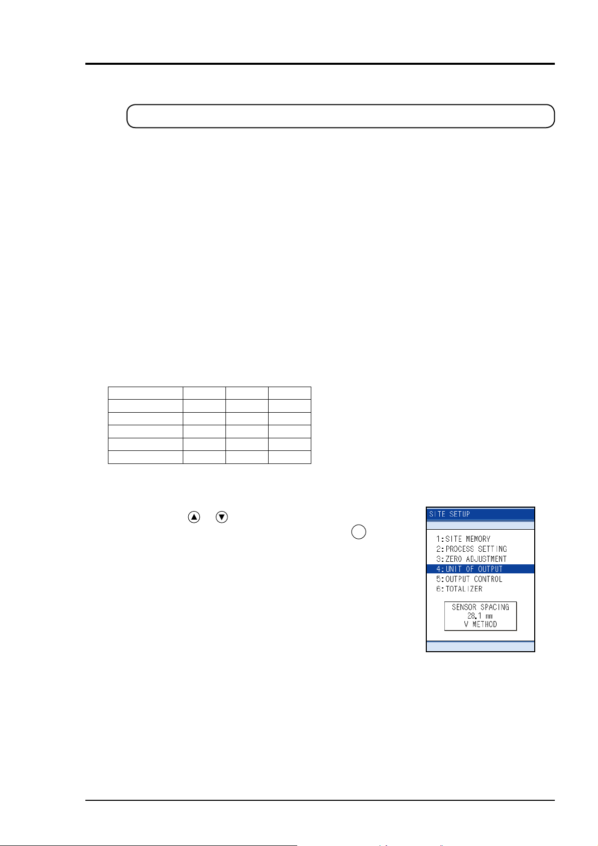
10.1.3 UNIT OF OUTPUT: when changing unit of each output
This function enables you to set unit of fl ow rate, total, temperature and total heat quantity.
Flow rate unit: Select the unit of fl ow rate and output range.
Metric system:
English system: gal/s, gal/min, gal/h, gal/d, kgal/d, Mgal/d, ft3/s, ft3/min, ft3/h, ft3/d, kft3/d, Mft3/d, BBL/s,
Flow rate total: Select the unit of fl ow rate.
Metric system:
English system: gal, kgal, ft3, kft3, Mft3, mBBL, BBL, kBBL, ACRE-ft
Temperature: Select the unit of temperature input.
Metric system: °C
English system: F, K
Heat fl ow: Select the unit of heat fl ow and output range.
Thermal total: Select the unit of total thermal.
Note) For the change of SYSTEM UNIT, refer to “10.3.1(2) SYSTEM UNIT”.
L/s, L/min, L/h, L/d, kL/d, ML/d, m3/s, m3/min, m3/h, m3/d, km3/d, Mm3/d, BBL/s, BBL/min,
BBL/h, BBL/d, kBBL/d, MBBL/d
BBL/min, BBL/h, BBL/d, kBBL/d, MBBL/d
mL, L, m3, km3, Mm3, mBBL, BBL, kBBL
, K
MJ/h, GJ/h, BTU/h, kBTU/h, MBTU/h
MJ, GJ, BTU, kBTU, MBTU
Direction of selected unit
Display Logger Printer
Flow rate unit
Flow rate total
Temperature
Heat fl ow
Thermal total
{{{: The unit selected by the unit of output is used.
{{{: The unit selected by measurement screen is used.
{{{
{{{
{{{
[Operation]
(1) Press the
or key on the SITE SETUP page and
select “UNIT OF OUTPUT”. Then, press the
key.
ENT
INF-TN1FSC-E 67

(2) Press the or key and move the cursor to the
output item of which unit to be changed.
ENT
(3) Press the
Select the unit by the
ENT
key.
key to open the unit selection screen.
or key and then press the
68 INF-TN1FSC-E

10.1.4 OUTPUT CONTROL: when controlling measured value (output control function)
This function enables you to set the value of damping, output calibration and low fl ow rate
cut off.
[Operation]
(1) Press the
or key on the “SITE SETUP” page
and select “OUTPUT CONTROL”. Then, press the
ENT
key and the OUTPUT CONTROL screen is dis-
played.
(2) Press the
or key and move the cursor to the
item of which output control setting to be changed,
ENT
and then press the
key.
For details of output control, refer to the items described in the following pages.
• For damping, refer to (1) “DAMPING”: when attenuating the variation of measured value.
• For output calibration, refer to (2) “OUTPUT CALIBRATION”: when calibrating measured
value.
• For low fl ow rate cut, refer to (3) “CUT OFF”: output cut off at low fl ow rate.
INF-TN1FSC-E 69

(1) “DAMPING” : when changing output response
Used for attenuating the variation of measured value.
A time constant is set. (Response time of about 63%)
Settable range: 0.0 to 100.0sec in 0.1 sec steps
[Operation]
63%
Flow rate
Time
Response time
(1) Press the
or key on the OUTPUT CONTROL
screen and select “DAMPING”. Then, press the
key, and the cursor moves to the set item, enabling
you to set the response time.
(2) Move the digit by pressing the
enter numeric values by using the
ENT
After entry, press the
key for setting.
or key and
or key.
ENT
70 INF-TN1FSC-E

(2) OUTPUT CALIBRATION ZERO/SPAN: when calibrating measured value
(output calibration function)
This function enables you to set
correction values.
[Settable range of zero point:
–5.000 m/s to 5.000 m/s]
[Settable range of span:
10 to 200%]
[Operation]
(1) Press the
or key on the OUTPUT CONTROL
screen and select “CALIBRATION ZERO” or
“CALIBRATION SPAN”. Then, press the
and the cursor moves to the set item, enabling you to
make zero/span setting.
Calculation of output value
Measured
value
Correction
Set span value
×
0
Zero point shift
ENT
key,
100
+ Set zero-point value
After correction
105
100
0 100
Output after correction
Flow (%)Flow velocity
Span shift
= Output value
Before correction
(2) Press the
or key to move the digit, and use the
or key to enter a numeric value. After entry,
ENT
press the
key for setting.
CAUTION
As output is corrected, measured value changes.
It is recommended to set as follows unless correction is required.
Zero point: 0.000 m/s
Span point: 100.00%
INF-TN1FSC-E 71

(3) CUT OFF: output cut off at low fl ow rate (low fl ow cutoff function)
When fl ow rate is extremely low, its output can
be cut off. (range: 0 to 5.000 m/s)
If fl uid in the pipe is moving due to convec-
tion, etc., even though the valve is closed, this
fl owmeter outputs a measured value. Therefore, values below an appropriate level should
be cut off.
[Operation]
Output
0.010m/s Flow velocity- 0.010m/s
(1) Press the
or key on the OUTPUT CONTROL
screen and select “CUT OFF”. Then, press the
key, and the cursor moves to the set item. Output cut
off point is settable.
(2) Move the digit by pressing the
enter a numeric value by pressing the
ENT
After entry, press the
key.
or key and
or key.
ENT
72 INF-TN1FSC-E

10.1.5 TOTALIZER: when performing the total process of measured data (totalize)
Total process and setting of total output can be performed.
(1) To start/set total output
[Operation]
(1) Select “TOTALIZER” on the SITE SETUP screen by
pressing the
Press the
screen.
(2) Pressing the
output mode.
Select the mode from MANUAL, FIXED TIME, and
TIMER by pressing the
(For details of MODE, refer to description of the
mode in the following page.)
or key.
ENT
key to display the total output selection
ENT
key enables you to select the total
or key.
(3) Move the cursor to “START” by the
ENT
and then press the
key.
or key,
The total will start.
(4) To stop the total output in the middle, move the cur-
ENT
sor to “STOP” and press the
key.
“STOP” is also possible from the totalizing calculation display button on the measurement screen.
CAUTION
Total will not start unless the cursor is pointed to “START”
ENT
and the
Even if the timer setting is performed after scheduled Start
date may pass than the time of the main unit, total will not
be carried out.
key is pressed.
INF-TN1FSC-E 73

Mode Description
“MANUAL” mode: Instant total starts
Without choosing STOP, total
continues.
“FIXED TIME” mode: Total starts after the time of set-
ting, total is performed within
the time selected from the
menu, and it stops automatically
after the time passed.
• 30min
• 1hour
• 1hour 30min
• 2hour
• 2hour 30min
• 3hour
“TIMER” mode: Set the time of total to start and
stop.
After each time is set, total
starts and stops automatically.
74 INF-TN1FSC-E

(2) To set total output
(1) Move the cursor to “SETTING” on the TOTAL screen by
or key.
the
ENT
Pressing the
or key.
the
Press the
“TOTALIZER PRESET”:
“TOTAL (THERMAL) PRESET”:
key enables you to select the set item by
ENT
key to make setting. (See the following.)
Preset the fl ow rate total to restart total.
[Settable range: 0.000 to 9999999999]
Preset the total heat quantity to restart
total.
[Settable range: 0.000 to 9999999999]
Resetting actual integral values should
be performed on the measurement
screen.
(See Page 58)
“ERROR (TOTAL)”: Determines how to dispose of the total
when the measurement status is abnormal on account of an empty pipe
interior or bubbles mixed in fl uid.
Settable range
HOLD: Stops total (as factory set)
NOT USED: Continues total according to a fl ow rate marked immediately
before the error occurrence.
“ERROR TIMER”: Sets the time from error occurrence to
error processing.
[Settable range: 0 to 900sec (factory
set: 10sec)]
The total continues until the burnout
timer is actuated.
INF-TN1FSC-E 75

10.2 Setting of data logger function
This function allows you to save measured values to the SD memory card, call the measured
data saved in the memory after measurement is completed, display, and produce output of data
on a printer.
Recording capacity: Depends on capacity of the SD memory card.
(1) How to view data logger
Call the logged measurement data, make the setting on graph display and print output.
Site name
Saved logger
data
(The green displays
under logging.)
Sets operation.
• Graph
• Print
Saved data capacity
Free space
Logger
Quick logger
Up to 100 items can be viewed by using the cursor.
For 100 or more, check SD memory card directly by your PC.
(2) How to view logging screen
This is the screen to set the stored fi le name, kind of measurement data and operation mode
which is stored to SD memory card.
Kind of measurment data
Logging name
Operation mode
Entry field for the name
76 INF-TN1FSC-E

10.2.1 “Logger Operation” mode
There are two logging modes, i.e., quick logger that permits operation from the measurement
screen and logger that is set from the menu screen. Logger is of two different modes, i.e.,
“CONTINUOUS” mode and “SET TIME” mode.
• Quick logger
• Logger
(1) “CONTINUOUS” mode
(2) “SET TIME” mode
(1) Quick logger
The quick logger starts when quick logger start button in the measurement screen is pressed.
The quick logger exits when a period of an hour has elapsed since it was started or when quick
logger stop button is pressed.
• Logging time: 1 hour, fi xed
• Cycle: 10 seconds, fi xed
• Measured data type: 3 types (unit and number of digits after decimal point are the same) displayed in measurement screen and status display
Startbutton
Measurementscreen
(2) Logger
(1) “CONTINUOUS” mode
“CONTINUOUS” mode is the mode to perform logging in a fi xed period from start date and
time to exit date and time.
Exit occurs upon elapse of exit date and time or when the stop button is pressed. As the exit
time varies by the start time and period, there are cases where it is different from the set exit
time.
• Logging time: Start date and time to exit date and time
• Cycle: 10 seconds to 24 hours
• Measured data type type: 14 measured data types and status display
INF-TN1FSC-E 77

Example) Case of setup of logging from 9/1 9:00PM to 9/8 4:00AM
• Start date and hour: 2008/09/01 21:00
• Exit date and hour: 2008/09/08 04:00
9/1 9/2 9/3
9/4 9/5 9/6 9/7
9/8
: Logging
: PM9:00
: AM4:00
(2) “SET TIME” mode
“SET TIME” mode is the mode to perform logging in a fi xed period only during a certain time
zone of a day between the start date and exit date.
Exit occurs upon elapse of exit time of exit period or when the stop button is pressed. As the
exit time varies by the start time and period, there are cases where it is different from the set exit
time.
The difference between start time and exit time is one hour at minimum. If the start time is
earlier than the exit time, logging is performed over 0 o’clock.
• Logging period: Start date to exit date
• Logging time: Start time to end time
• Period: 10 seconds to 23 hours
• Measured data type: 14 measured data types and status display
Example) Case of setup of logging for one week from 9/1, from 9:00PM to 4:00AM
• Period: 9/1 to 9/8
• Start date and hour: 21:00
• Exit date and hour: 04:00
9/1 9/2 9/3
9/4 9/5 9/6 9/7
9/8
: Logging
: 21:00
: 04:00
(3) Measured data type
The measurement data is following 14kind.
VELOCITY
FLOW RATE
FLOW RATE (%)
+TOTALIZER
–TOTALIZER
AI CHANNEL 1
AI CHANNEL 2
SUPPLY TEMP.
RETURN TEMP.
TEMP DIFFERENCE
THERMAL FLOW
THERMAL FLOW (%)
+TOTAL (THERMAL)
–TOTAL (THERMAL)
78 INF-TN1FSC-E

10.2.2 Logger data fi le format
One logger fi le is composed of fi les of two types indicated below. The data fi le is stored as
divided by 65,500 lines for permitting high-speed access and due to restrictions in the maximum
number of lines of CSV display of Microsoft Excel.
File type File name Remarks
Confi guration fi le (Logging name)_(date)_(hour).ini Means logger start time and relevant logger
Data fi le (Logging name)_(date)_(hour).csv Logging data in a specifi c period
The maximum number of data fi les in a logger is 20 fi les in case of a “CONTINUOUS” logger,
and is 550 fi les in case of a ”SET TIME” logger. The appointed time logger is of one fi le per
day.
Note) After reaching the maximum data fi le, the logging will be stopped.
The logger data list shows the following names excluding extension (.ini) of logger confi gura-
tion fi les.
• Logger … “Logger name_(start date)_(start hour)”
• Quick logger … “QUICK__(start date)_(start hour)”
If capacity shortage arises during logging operation, logging operation stops with the following
screen displayed.
When this screen appears, replace the SD memory card immediately.
ESC
Press the
key, or remove SD memory card, the message will be cleared.
data fi les.
Move the cursor to “STOP” to stop logging, press the
card.
ENT
key, and once remove the memory
INF-TN1FSC-E 79

10.2.3 LOGGING: when logging (recording) measured data
“LOGGING” only sets logging conditions.
To start logging, follow the steps (2) to (8) given shown below.
[Operation]
(1) Press the
select “LOGGING” and press the
or key on the LOGGING screen to
ENT
(2) Register the name of the logger.
ENT
Press the
key after the cursor is placed in the
“NAME”.
The cursor moves to the character entry fi eld.
key.
(3) Register the place or the pipe name for logging.
Refer to Page 24 and 25 to enter characters.
(4) Select the kind of data to be logged.
Move the cursor pointed from “NAME” to “KIND”
by the
Then, press the
key.
ENT
key, and the cursor moves to
kinds of data.
80 INF-TN1FSC-E

(5) Select the kind of data by the or key and press
ENT
the
key so that the selected data will be logged.
One or more items are simultaneously selectable.
Press the
key to display kind of data on the second
page.
(6) After selection, return the cursor to “KIND” by the
ESC
key.
(7) Set the logging operation mode. Move the cursor
pointed from “KIND” to “MODE” by the key.
ENT
(8) Press the
key, and the cursor moves to “CONTINUOUS”.
Then, press the
key to move the cursor to “SET
TIME”.
CAUTION
• Do not remove the memory card while data is written in it. Otherwise the logger data can
not be read.
• Do not turn the power off during reading the data to memory card. Otherwise the logger
data can’t be read.
INF-TN1FSC-E 81

(9) Press the
ENT
key to move the cursor to the set item
“CONTINUOUS” or “SET TIME”.
• Setting of “CONTINUOUSNESS”
Sets the start time, the fi nish time, and the logging
cycle.
ENT
Move the cursor to “START” and press the
key to
start logging.
• Setting of “APPOINT TIME”
Sets the logging period, the start/fi nish time, and the
logging cycle.
ENT
Move the cursor to “START” and press the
key to
start logging.
CAUTION
• In case heat mode is “NOT USED”, it is invalid even if sending temperature and subsequent
have been selected.
• If the output unit or system unit was changed after logger start, logging is performed in the
unit at the time of start. The changed unit becomes valid after the logger is stopped.
• Start-up is not permitted if the set time is later than the time of the main unit clock. Make sure
to set a time with a margin of several minutes after the present time.
82 INF-TN1FSC-E

10.2.4 “LOGGER DATA”: when checking or printing logged data
(1) When checking logged data on screen
[Operation]
(1) Press the
select “LOGGER DATA” and press the
or key on the LOGGER screen,
ENT
key.
(2) When the LOGGER DATA screen appears, press the
ENT
key.
(3) The MODE screen appears.
Select “GRAPH DISP.” and press the
ENT
key.
(4) Select the name (No.) of logger data by pressing the
or key. and press the
ENT
key. The graph dis-
play screen opens.
INF-TN1FSC-E 83
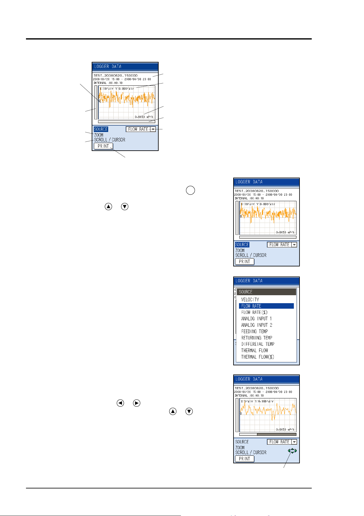
Mode Description
Cursor
Displays logging conditions.
Graduation interval
Data axis zoom bar
(vertical axis).
Enlarging the graph
Movement of
data axis,
time axis and
cursor display
Prints the data within the display range in graph format.
(5) To change kind of data to be displayed:
Move the cursor to “SOURCE” and press the
to enter the SOURCE screen. Select the kind of data
by pressing the
or key.
Note) Display only types of logged data.
Data value at the position of cursor
Time axis zoon bar (Horizontal axis).
Kind of data
(Displays kind of data displayed on
the graph)
ENT
key
(6) To change scale of time axis (horizontal axis) and
data axis (vertical axis):
Move the cursor to “ZOOM” to enlarge or contract
the time axis by the
Enlarge or contract the data axis by the
or key.
or key.
Enlarge/contract
84 INF-TN1FSC-E
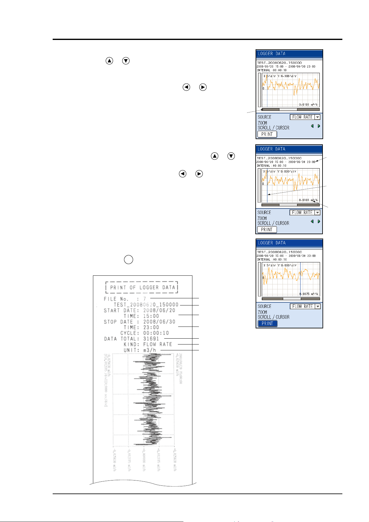
(7) For moving time axis
Press
or key, move the cursor to “SCROLL”
and then press the ENT key, SCROLL will be readied.
For moving time axis, please use
or key.
(8) To display data values of cursor:
Move the cursor to “CURSOR” by pressing
key.
Move the cursor by pressing the
or key to dis-
play the data value of the time.
Scroll bar
or
Time
Cursor
Data
(9) To print graph:
Move the cursor to “PRINT” and print a graph by
ENT
pressing the
key.
File No. of logger data
Name of logger data
Starting time/date
Ending time/date
The number of logger data
Kind of data (source)
Unit of printing data
INF-TN1FSC-E 85

(2) When printing logged data in text
[Operation]
(1) Press the
select “LOGGER DATA” and press the
or key on the LOGGER screen,
ENT
key.
(2) When the “LOGGER DATA” screen appears, press
ENT
the
key.
(3) The MODE screen appears.
Select “PRINT” and press the
ENT
key.
(4) Press the
data (No.) and press the
or key to select the name of logger
ENT
key to display the print-
out screen.
(5) Set the printing conditions.
Then, move the cursor to “PRINT” and press the
key.
ENT
86 INF-TN1FSC-E

[Example]
r
22321 data are saved in the “A” logger data every 10 seconds between 2008/06/13 18:00 and
2008/06/16 8:00 (o’clock). The logger data from the 7th (at 18:01) to the 367st (at 19:01) are
printed out every 600 seconds.
Name and condition of
selected logger data
Total of logged data
Printing conditions of
logger data above
1. Select “START DATA POSI.”
and press .
ENT
Change to 7 by the or
keys.
2. Select “STOP DATA POSI.”
and press .
ENT
Change to 361 by the o
keys.
3. Select “CYCLE” and press
ENT
.
Change to 00:10:00 by the
or keys.
4. Select “PRINT” and press ,
ENT
and printing is started.
INF-TN1FSC-E 87

10.3 Setting of system (SYSTEM SETUP screen)
This system allows you to accomplish the BASIC SETUP (system setup such as setup of clock
and measurement unit), the ANALOG INPUT/OUTPUT (analog input setting and input/output
calibration) and the CALORIE MODE (setting of mode, operation and temperature).
10.3.1 BASIC SETUP: when setting the system
(1) Select “BASIC SETUP” on the SYSTEM screen.
ENT
Press the
screen.
(1) “CLOCK”: when setting the clock (set the present time)
key to display the BASIC SETUP
(1) Press the or key on the BASIC SETUP screen
and select “CLOCK”.
ENT
Press the
key, and the cursor moves to “DATE
DISPLAY”.
ENT
Press the
key to display the Date DISPLAY
screen.
Select the display of date by the
ENT
press the
key.
or key, and
YYYY : Year
MM : Month
DD : Day
88 INF-TN1FSC-E

(2) Move the cursor to SET DATE/TIME by the or
key and press the
ENT
key so that time and date
can be set.
Move the digit by the
values by the
or key.
After entry, press the
or key and enter numeric
ENT
key.
The setup time is set at this point.
Setup contents
2008/02/01 10:03
(year, month, day, hour, minute)
CAUTION
When using the total or the data logger or the timer function of the printer, time setting can not be
operated. Stop the timer function, and then set it again.
INF-TN1FSC-E 89

(2) SYSTEM UNIT: when setting the measurement and setting unit system
[selection of meter system and inch system]
[Operation]
(1) Select “SYSTEM UNIT” by the
or key on the
BASIC SETUP screen.
ENT
Press the
key, and the SYSTEM UNIT screen is
displayed.
(2) Select “METRIC” or “ENGLISH” by the
ENT
key and press the
key.
Note: For using of Inch, please select “ENGLISH”.
or
90 INF-TN1FSC-E

(3) “LCD POWER OFF”: when setting time for extinguishing LCD.
[To turn off LCD automatically]
Set the LCD off time (the setting range is from 0 to 30min)
If key operation is not performed, the backlight of the LCD (screen) goes off automatically and
then the power of LCD will be OFF. If key operation is performed while the backlight is kept
off, it comes on.
If 0 min. is selected for OFF time, the light is kept ON.
LCD POWER OFF
LCD ON
Key operation
[Operation]
(1) Press the
and select “LCD POWER OFF”.
Press the
ENT
off time.
(2) Move the digit by the
values by pressing the
After entry, press the
LCD POWER OFF
2
LCD OFF LCD Power OFF
2
or key on the BASIC SETUP screen
key, and you are ready to set the LCD
or key and enter numeric
or key.
ENT
key.
INF-TN1FSC-E 91
 Loading...