

Page 1
Installation, Operation, Service, and Parts Manual
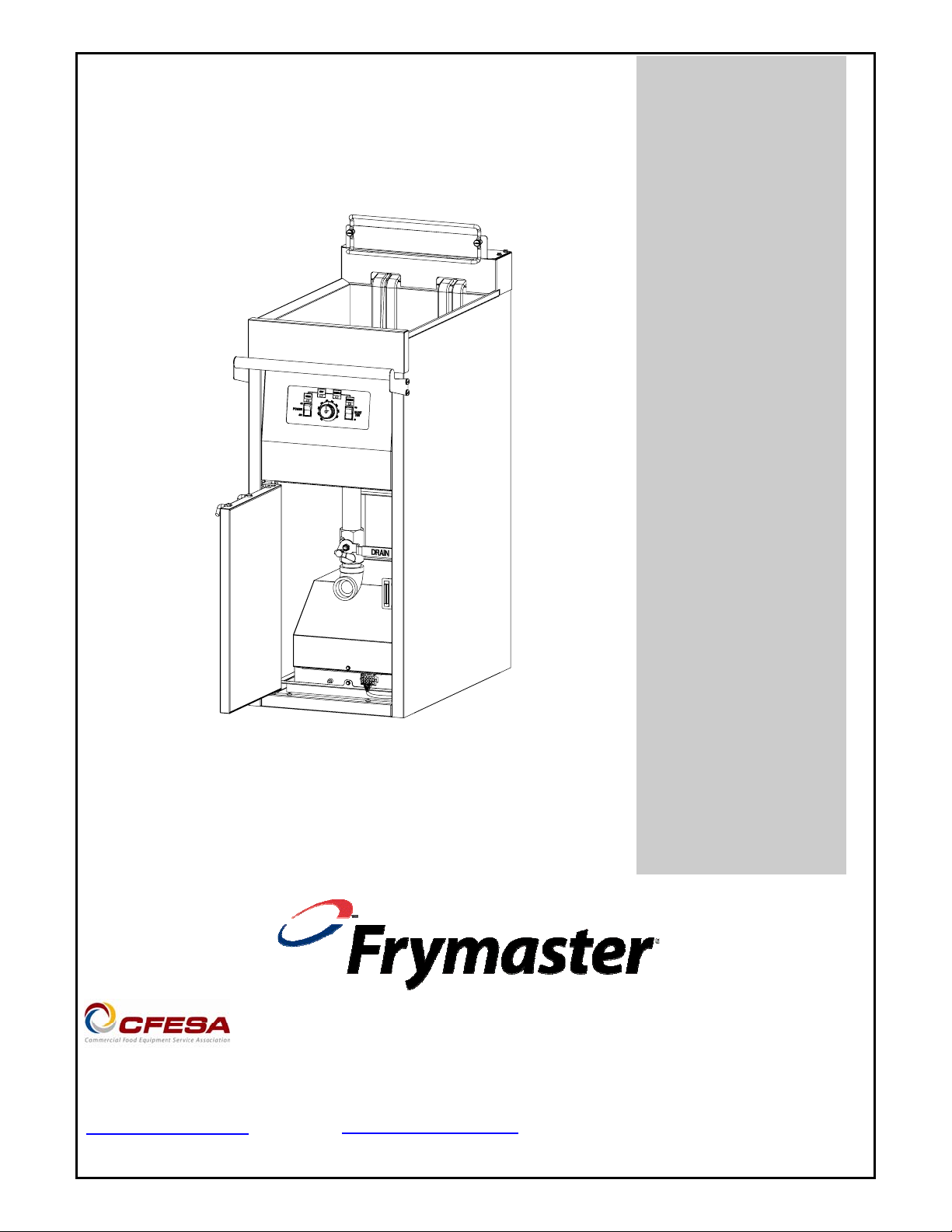
NAVY SUBMARINE
ELECTRIC FRYER
www.frymaster.com
Frymaster, a member of the Commercial Food Equipment Service Association, recommends
using CFESA Certified Technicians.
24-Hour Service Hotline 1-800-551-8633
E-mail: service@frymaster.com
OCTOBER 11
*8196030A*
Page 2
NOTICE
IF, DURING THE WARRANTY PERIOD, THE CUSTOMER USES A PART F OR THIS MANITOWOC
FOOD SERVICE EQUIPMENT OTHER THAN AN UNMODIFIED NEW OR RECY CLED PART
PURCHASED DIRECTLY FROM FRYMASTER/DEAN, OR ANY OF ITS AUTHORIZED SERVICERS,
AND/OR THE PART BEING USED IS MODIFIED FROM ITS ORIGINAL CONFIGURATION, THIS
WARRANTY WILL BE VOID. FURTHER, FRYMASTER/DEAN AND ITS AFFILIAT ES WILL NOT BE
LIABLE FOR ANY CLAIMS, DAMAGES OR EXPENSES INCURRED BY THE CUSTOMER WHICH
ARISE DIRECTLY OR INDIRECTLY, IN WHOLE OR IN PART, DUE TO THE INSTALLATION OF
ANY MODIFIED PART AND/OR PART RECEIVED FROM AN UNAUTHORIZED SERVICER.
DANGER
Copper wire suitable for at least 167°F (75°C) must be used for power connections.
DANGER
The electrical power supply for this appliance must be the same as indicated on the
rating and serial number plate located on the inside of the fryer door.
DANGER
This appliance must be connected to the voltage and phase as specified on the rating
and serial number plate located on the inside of the fryer door.
DANGER
All wiring connections for this appliance must be made in accordance with the wiring
diagrams furnished with the equipment. Wiring diagrams are located on the inside of
the fryer door.
DANGER
Do not store or use gasoline or other flammable vapors and liquids in the vicinity of this
or any other appliance.
WARNING
Do not use water jets to clean this equipment.
Page 3

Navy Submarine Electric Fryers
Installation, Operation, Service, and Parts Manual
TABLE OF CONTENTS
Page
Chapter 1: Introduction
Chapter 2: Installation Instructions 2-1
Chapter 3: Operating Instructions 3-1
Chapter 4: Filtration Instructions 4-1
Chapter 5: Preventive Maintenance 5-1
Chapter 6: Operator Troubleshooting 6-1
Chapter 7: Service Procedures 7-1
Chapter 8: Parts List 8-1
1-1
i
Page 4
NAVY SUBMARINE ELECTRIC FRYER
CHAPTER 1: INTRODUCTION
1.1 General
Read the instructions in this manual thoroughly before attempting to operate this equipment. This
manual covers the Frymaster Navy Submarine Electric Fryer, a 440V 14kW 3-phase fryer that has
been specifically configured for use aboard submarines of the U.S. Navy.
1.2 Safety Information
Before attempting to operate your unit, read the instructions in this manual thoroughly.
Throughout this manual, you will find notations enclosed in double-bordered boxes similar to the
one below.
Hot cooking oil causes severe burns. Never attempt to move a fryer containing hot
cooking oil/shortening or to transfer hot cooking oil/shortening from one container
to another.
CAUTION boxes contain information about actions or conditions that may cause or result in a
malfunction of your system.
WARNING boxes contain information about actions or conditions that may cause or result in
damage to your system, and which may cause your system to malfunction.
DANGER boxes contain information about actions or conditions that may cause or result in
injury to personnel, and which may cause damage to your system and/or cause your system to
malfunction.
Fryers in this series are equipped with two high-temperature detection features that shut off
power to the unit by means of an external shunt trip disconnect should the temperature
controls fail.
1.3 Controller Information
This equipment has been tested and found to comply with the limits for a Class A digital device,
pursuant to Part 15 of the FCC rules. While this device is a verified Class A device, it has been
shown to meet the Class B limits. These limits are designed to provide reasonable protection against
harmful interference when the equipment is operated in a shipboard environment. This equipment
generates, uses, and can radiate radio frequency energy and, if not installed and used in accordance
with the instruction manual, may cause harmful interference to radio communications and other
electronic devices.
DANGER
1-1
Page 5

1.4 Shipping Damage Claim Procedure
What to do if this equipment arrives damaged:
Please note that this equipment was carefully inspected and packed by skilled personnel before
leaving the factory. The freight company assumes full responsibility for safe delivery upon
acceptance of the equipment.
1. File Claim for Damages Immediately—Regardless of extent of damage.
2. Visible Loss or Damage—Be sure this is noted on the freight bill or express receipt and is signed
by the person making the delivery.
3. Concealed Loss or Damage—If damage is unnoticed until equipment is unpacked, notify the
freight company or carrier immediately and file a concealed damage claim. This should be done
within 15 days of date of delivery. Be sure to retain container for inspection.
1.5 Service Information
For non-routine maintenance or repairs, or for service information, contact your local Frymaster
Authorized Servicer (FAS). A list of Frymaster Factory Authorized Servicers (FAS’s) is located on
the Frymaster website at www.frymaster.com. Service information may also be obtained by calling
the Frymaster Technical Services Department (1-800-551-8633). The following information will be
needed in order to assist you efficiently:
Model Number:
Serial Number:
Voltage:
Also be prepared to describe the specific problem.
RETAIN AND STORE THIS MANUAL IN A SAFE PLACE FOR FUTURE USE.
1-2
Page 6
NAVY SUBMARINE ELECTRIC FRYER
CHAPTER 2: INSTALLATION INSTRUCTIONS
2.1 General
Proper installation is essential for the safe, efficient, trouble-free operation of this appliance.
Any unauthorized alteration of this equipment will void the Frymaster warranty.
NOTICE
If this equipment is wired directly into the electrical power supply, a means for
disconnection from the supply having a contact separation of at least 3-mm in all
poles must be incorporated in the fixed wiring.
NOTICE
This equipment must be positioned so that the plug is accessible unless other
means for disconnection from the power supply (e.g., a circuit breaker) is provided.
NOTICE
If this appliance is permanently connected to fixed wiring, it must be connected by
means of copper wires having a temperature rating of not less than 167°F (75°C).
NOTICE
If the electrical power supply cord is damaged, it must be replaced by a
Frymaster/Dean Factory Authorized Servicer technician or a similarly qualified
person in order to avoid a hazard.
DANGER
This appliance must be connected to a power supply having the same voltage and
phase as specified on the rating plate located on the inside of the appliance door.
DANGER
All wiring connections for this appliance must be made in accordance with the
wiring diagram(s) furnished with the appliance. Refer to the wiring diagram affixed
to the inside of the appliance door when installing or servicing this equipment.
DANGER
The appliance area must be kept free and clear of combustible material at all times.
All installation and service on FRYMASTER equipment must be performed by qualified, certified,
licensed, and/or authorized installation or service personnel.
Service may be obtained by contacting a local Frymaster/DEAN Factory Authorized Servicer.
In the event of a power failure, the fryer will automatically shut down. If this occurs, turn the power
switch OFF. Do not attempt to start the fryer until power is restored.
2-1
Page 7
A clearance of 6 inches (15cm) must be provided at both sides and back adjacent to combustible
A
construction. A minimum of 24 inches (61cm) should be provided at the front of the equipment for
servicing and proper operation.
Connections should be made by means of an approved, flexible-metallic or rubber-covered electrical
cable and quick-disconnect plug. The fryers may be installed with “hard-wired” connections, but
use of quick-disconnect plugs will facilitate service if required. Connections are made to the fryer
power input terminal block located in the contactor box in the bottom of the fryer.
DANGER
Observe the following precautions when connecting the fryer to an emergency cutoff
system:
● Be sure that each fryer is connected to a dedicated set of contacts in the
emergency cutoff system.
● Do not connect the contacts in series.
● Do not connect more than one fryer to each set of contacts.
● The contacts MUST be normally closed contacts that open in an emergency.
● The contacts CANNOT have an external voltage applied.
2.2 Power Requirements
WIRE
MODEL VOLTAGE PHASE
H14 (Submarine) 440 3 3 8 (10) 19 19 19
SERVICE
MIN.
SIZE
AWG
(mm2)
MPS PER LEG
L1 L2 L3
NOTICE
If this appliance is permanently connected to fixed wiring, it must be connected by
means of copper wires having a temperature rating of not less than 167°F (75°C).
DANGER
This appliance must be connected to a power supply having the same voltage and
phase as specified on the rating plate located on the inside of the appliance door.
DANGER
All wiring connections for this appliance must be made in accordance with the
wiring diagram furnished with the appliance. Refer to the wiring diagram affixed to
the inside of the appliance door when installing or servicing this equipment.
2-2
Page 8
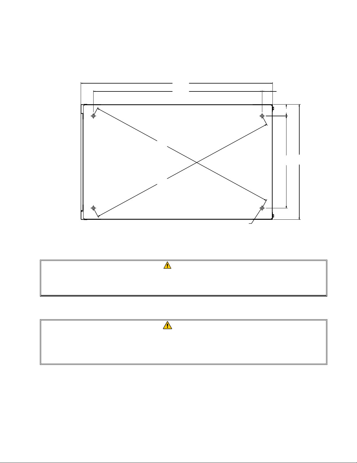
2.3 Installation
1. This equipment must be securely bolted to the deck.
2. Install deck studs for the specific fryer configuration in accordance with the diagram below.
25.00
22.00 1.37
1.50
25.06
FRONT
25.06
MOUNTING HOLES
Ø.375
4 PLACES
12.00
15.00
3. Position the fryer on the deck studs and secure with appropriate nuts and lock washers.
DANGER
No structural material on the fryer should be altered or removed to accommodate
placement of the fryer under a hood. Questions? Call the Frymaster/Dean Service
Hotline at 1-800-551-8633.
2.4 After Fryer is Anchored at the Frying Station
DANGER
Hot shortening can cause severe burns. Avoid contact. Under all circumstances, oil
must be removed from the fryer before attempting to move it to avoid oil spills, falls
and severe burns. This fryer may tip and cause personal injury if not secured in a
stationary position.
1. Close the frypot drain-valve and fill the frypot with water to the bottom oil level line.
2. Boil out the frypot in accordance with the instructions in Section 5.1.3 of this manual.
3. Drain, clean, and fill the frypot with cooking oil. (See Equipment Setup and Shutdown
Procedures in Chapter 3.)
2-3
Page 9
NAVY SUBMARINE ELECTRIC FRYER
CHAPTER 3: OPERATING INSTRUCTIONS
3.1 Equipment Setup and Shutdown Procedures
Setup
DANGER
Never operate the appliance with an empty frypot. The frypot must be filled with
water or cooking oil/shortening before energizing the elements. Failure to do so will
result in irreparable damage to the elements and may cause a fire.
DANGER
Remove all drops of water from the frypot before filling with cooking oil or
shortening. Failure to do so will cause spattering of hot liquid when the oil or
shortening is heated to cooking temperature.
1. Fill the frypot with cooking oil to the bottom OIL LEVEL line located on the rear of the frypot.
This will allow for oil expansion as heat is applied. Do not fill cold oil any higher than the
bottom line; overflow may occur as heat expands the oil.
NOTE: If solid shortening is used, it should be pre-melted outside the frypot then transferred to
the frypot. If the solid shortening is not pre-melted, it must be packed down between the
elements into the bottom of the frypot.
DANGER
Never set a complete block of solid shortening on top of the heating elements.
When using solid shortening, always pre-melt the shortening before adding it to the
frypot. If the shortening is not pre-melted, it must be packed down into the bottom of
the frypot and between the elements, and the fryer must be started in the melt-cycle
mode.
Never cancel the melt-cycle mode when using solid shortening. Doing so will result
in damage to the elements and increase the potential for a flash fire.
2. If the fryer is not hard-wired into the power supply, ensure that the power cord is plugged into
the appropriate receptacle. Verify that the face of the plug is flush with the outlet plate, with no
portion of the prongs visible.
3. Ensure that the oil/shortening level is at the top OIL LEVEL line when the oil/shortening is at its
cooking temperature. It may be necessary to add oil/shortening to bring the level up to the
proper mark, after it has reached cooking temperature
.
3–1
Page 10
Shutdown
1. Turn the fryer off.
2. Filter the cooking oil/shortening and clean the fryers (See Chapters 4 and 5).
3. Place the frypot covers on the frypots.
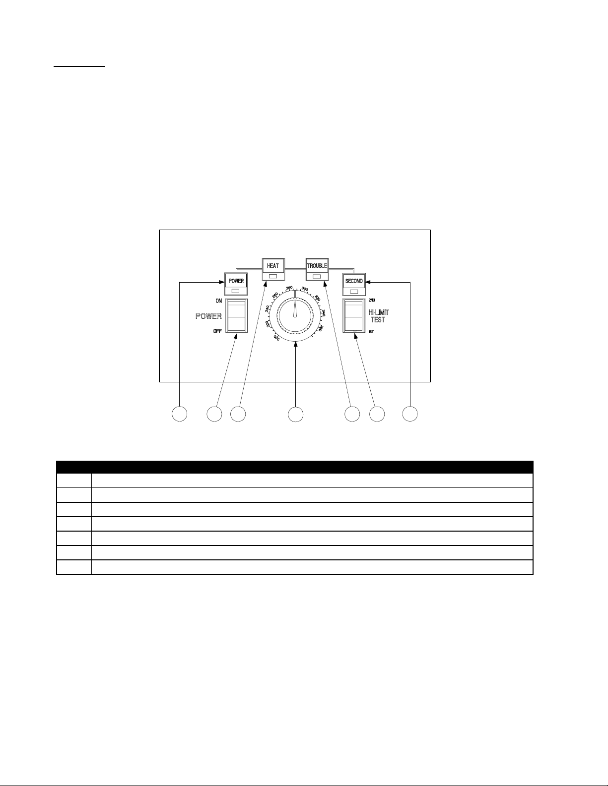
3.2 Operation of the Solid-State Analog Controller
Fryers configured for the U.S. Navy are equipped with solid-state analog controllers, illustrated
below.
2 7
1 3 4
U.S. Navy Solid-State Analog Controller
5
6
ITEM DESCRIPTION
1 Power Switch – Controls electrical power to fryer.
2 Power-On Light – Indicates when electrical power to fryer is ON.
3 Heating Mode Light – Indicates when heating element is ON.
4 Trouble Light – Indicates over high-limit or problem in heat control circuitry.
5 Thermostat Control Knob – Sets desired frying temperature.
6 Hi-Limit Test Switch – Tests high-limit thermostat.
7 Second Hi-Limit Test Light – Indicates fryer is in second high-limit test mode.
The analog controller is used to adjust and maintain oil at the temperature indicated by the
thermostat knob.
The fryer has two built-in high-limit protection features. If the temperature in the frypot reaches
approximately 410°F, the controller opens the heat relay circuit, turning the elements off. If the
temperature in the frypot reaches 450°F, a mechanical high-limit shuts off electrical power to the
fryer The operator should periodically test each of the high-limit protection features, using the
procedure at the end of this chapter, to verify that they are operating correctly.
The analog controller has no timing features. The operator must monitor shake and pull times.
3–2
Page 11
CONTROLLER OPERATING PROCEDURE
1. Verify that the thermostat knob is set to the desired cooking temperature.
2. Press the power switch to the ON position. The POWER light will illuminate.
WARNING
Before pressing the power switch to the ON position, ensure that the frypot is
properly filled with oil. See Section 3.1.
3. If the frypot temperature is below 180°F, the controller will automatically enter a warm-up cycle
(often called a melt cycle). The heating elements will cycle on and off repeatedly, allowing the
oil to heat gradually, without scorching. During the warm-up cycle, the heating mode light will
alternately illuminate and go off as the elements cycle on and off. Within about 45 minutes, the
controller will exit the warm-up cycle and the heating mode light will remain continuously
illuminated.
4. When the oil temperature reaches the thermostat knob setpoint, the elements will cycle OFF and
the HEAT light will go off, indicating that the fryer is ready for the cooking process to begin.
HI-LIMIT TEST PROCEDURE
Tools Required: One 0-600°F pyrometer with sensing probe or an equivalent high-temperature
thermometer.
NOTE: Conduct this test when the fryer will not be needed for about one hour and when the
cooking oil is due to be changed (the test will ruin the cooking oil). Start the test with the controller
turned ON and with the cooking oil at normal frying temperature. Stir the oil thoroughly to ensure
even distribution and temperature.
DANGER
If the expected results (indicated by italics) for Steps 3 and 4 below do not occur,
turn off the fryer at the main circuit breaker panel and do not use the fryer until it has
been repaired by an authorized technician.
1. Verify that cooking oil is at the bottom OIL-LEVEL line. Add oil if necessary.
2. Turn the power switch ON and set the control knob to the normal frying temperature.
3. Insert the pyrometer probe into the frypot so that its tip is near the temperature probe on the
element (i.e., approximately 1½-inch into the oil, near the center of the frypot). Press and hold
the high limit test switch in the “1ST” test position until the TROUBLE light illuminates.
Release the test switch.
The trouble light should have come on when the temperature was approximately 410°F (± 3°F)
and the heating elements should have de-energized (indicated by the HEAT light going out).
3–3
Page 12

4. Press and hold the high limit test switch in the “2ND” test position until the SECOND light
illuminates. Release the switch.
The light should have come on when the temperature was between 430°F and 460°F.
For fryers connected to an external shunt power supply, all fryers should have been shut off
completely and all control panel lights should have been extinguished. For fryers not connected
to an external shunt power supply, only the fryer being tested should have been shut off.
5. Place the controller power switch in the OFF position.
6. Allow the cooking oil to cool to below normal frying temperature.
When the power switch is again placed in the ON position, the elements should re-energize and
the operating thermostat should resume control of the temperature. If the TROUBLE light
remains on instead, allow the oil additional time to cool.
3–4
Page 13

NAVY SUBMARINE ELECTRIC FRYER
CHAPTER 4: DRAINING AND FILTERING INSTRUCTIONS
4.1 Introduction
Submarine fryers are not equipped with built-in filtration. They must be manually drained and
filtered.
4.2 Draining and Disposing of Waste Oil
Turn the fryer off and allow the oil/shortening to cool to 100°F. Screw the drain extension furnished
with the fryer into the drain valve, then open the valve and drain the oil/shortening into the drain pan
furnished with the fryer for transport to a disposal container. When draining is finished, close the
fryer drain valve securely.
DANGER
Make sure the fryer is off before draining. Allow the oil/shortening to cool to 100°F
before draining into an appropriate container for disposal.
4.3 Filtering
To prolong the life of your cooking oil or shortening and to ensure high quality fried foods, the oil or
shortening should be filtered on a routine basis.
The frequency of filtering depends upon how often the oil is used, how much food is fried, and the
type of food fried. As a minimum, the oil should be filtered each time the frypot is emptied.
However, the more you fry, the more you will need to filter. Frying produces sediment. Sediment
accumulation has two effects. First, it reduces the efficiency of the fryer. Second, it has a tendency
to scorch, which results in bad tasting food. Food that produces a large amount of sediment, such as
breaded fish products, require that the oil be filtered more often than foods such as french-fries,
which produce comparatively little sediment.
To aid in the filtering process, a filter cone holder and paper filter cones may be ordered from
Frymaster FASs or kitchen equipment suppliers. To order the cone holder, use P/N 803-0072. To
order a box of 50 filters, use P/N 803-0042. To order a case containing 500 filters, use P/N 803-
0075.
4-1
Page 14

NAVY SUBMARINE ELECTRIC FRYER
CHAPTER 5: PREVENTIVE MAINTENANCE
5.1 Cleaning the Fryer
Never attempt to clean the fryer during the frying process or when the frypot is filled
with hot oil/shortening. If water comes in contact with oil/shortening heated to frying
temperature, it will cause spattering of the oil/shortening, which can result in severe
burns to nearby personnel.
Use a commercial-grade cleaner formulated to effectively clean and sanitize
food-contact surfaces. Read the directions for use and precautionary statements
before use. Particular attention must be paid to the concentration of cleaner and the
length of time the cleaner remains on the food-contact surfaces.
5.1.1 Clean Inside and Outside of the Fryer Cabinet – Daily
Clean inside the fryer cabinet with a dry, clean cloth. Wipe all accessible metal surfaces and
components to remove accumulated oil/shortening and dust.
Clean outside the fryer cabinet, with a clean, damp cloth soaked with dishwashing detergent. Wipe
with a clean, damp cloth.
5.1.2 Clean the Frypot and Heating Elements – Weekly
DANGER
WARNING
DANGER
Never operate the appliance with an empty frypot. The frypot must be filled with
water or cooking oil/shortening before energizing the elements. Failure to do so will
result in irreparable damage to the elements and may cause a fire.
Boiling-Out the Frypot
Before the fryer is first used, it should be boiled out to ensure that residue from the manufacturing
process has been eliminated. Also, after the fryer has been in use for a period of time, a hard film of
caramelized vegetable oil will form on the inside of the frypot. This film should be periodically
removed by following the boil-out procedure that follows.
1. Before switching the fryer ON, close the frypot drain valve, then fill the empty frypot with a
mixture of cold water and dishwashing detergent. Follow instructions on detergent container
when mixing.
2. Press the fryer ON/OFF switch to the ON position.
3. Set the temperature control knob to the lowest setting.
5–1
Page 15

4. Simmer the solution for 45 minutes to one hour. Do not allow the water level to drop below the
bottom oil-level line in the frypot during the boil-out operation.
DANGER
Never leave the fryer unattended during the boil-out process. If the boil-out solution
boils over, turn the fryer off immediately and let the solution cool for a few minutes
before resuming the process.
5. Turn the fryer ON/OFF switch to the OFF position.
6. Add two gallons of water. Drain out the solution and clean the frypot(s) thoroughly.
7. Refill the frypot with clean water. Rinse the frypot twice, drain and dry with a clean towel.
Thoroughly remove all water from the frypot and elements before refilling the frypot with
cooking oil/shortening.
DANGER
Remove all drops of water from the frypot before filling with cooking oil or
shortening. Failure to do so will cause spattering of hot liquid when the oil or
shortening is heated to cooking temperature.
5.1.3 Clean Detachable Parts and Accessories – Weekly
Wipe all detachable parts and accessories with a clean, dry cloth. Use a clean cloth saturated with
detergent to remove accumulated carbonized oil/shortening on detachable parts and accessories.
Rinse the parts and accessories thoroughly with clean water and wipe dry before reinstalling.
5.2 Check Calibration of Temperature Control Knob – Monthly
1. After the cooking oil/shortening reaches operating temperature, let the heating elements cycle at
least four times (indicated by the HEAT light going out and coming back on).
2. Insert a thermometer or pyrometer probe near the temperature-sensing probe approximately three
inches deep into the cooking oil/shortening. When the heating elements cycle on for the fourth
time, the thermometer should read within ±5°F of the temperature control knob setting.
3. If the knob requires adjustment:
a. Loosen the setscrew in the control knob until the outer shell of the knob will rotate on the
insert inside the knob.
b. Rotate the outer shell of the knob until the index line on the knob aligns with the mark that
corresponds to the thermometer or pyrometer reading.
c. Hold the knob and tighten the setscrew.
d. Recheck the thermometer or pyrometer reading and the temperature control knob setting the
next time the HEAT light illuminates.
5–2
Page 16

e. Repeat steps a through d until the thermometer or pyrometer reading and the knob setting
agree within 5°F.
5.3 Annual/Periodic System Inspection
This appliance should be inspected and adjusted periodically by qualified service personnel as
part of the galley material maintenance management (3M) program.
Frymaster recommends that a Factory Authorized Servicer inspect this appliance at least
annually as follows:
Fryer
• Inspect the cabinet inside and out, front and rear for excessive oil build-up and/or oil migration.
• Verify that the heating element wires are in good condition and that leads have no visible fraying
or insulation damage and that they are free of oil migration build-up.
• Verify that heating elements are in good condition with no carbon/caramelized oil build-up.
Inspect the elements for signs of extensive dry-firing.
• Verify the heating-element amp-draw is within the allowed range as indicated on the appliance’s
rating plate.
• Verify that the temperature and high-limit probes are properly connected, tightened and
functioning properly, and that mounting hardware and probe guards are present and properly
installed.
• Verify that component box and contactor box components (i.e. controller, relays, interface
boards, transformers, contactors, etc.) are in good condition and free from oil migration build-up
and other debris.
• Verify that component box and contactor box wiring connections are tight and that wiring is in
good condition.
• Verify that all safety features (i.e. contactor shields, shunts, reset switches, etc.) are present and
functioning properly.
• Verify that the frypot is in good condition and free of leaks and that the frypot insulation is in
serviceable condition.
• Verify that all wiring harnesses and wiring connections are tight and in good condition.
5-3
Page 17

NAVY SUBMARINE ELECTRIC FRYER
CHAPTER 6: OPERATOR TROUBLESHOOTING
6.1 Introduction
This section provides an easy reference guide to some of the common problems that may occur
during the operation of this equipment. The troubleshooting guides that follow are intended to help
correct, or at least accurately diagnose, problems with this equipment. Although the chapter covers
the most common problems reported, you may encounter problems that are not covered. In such
instances, the Frymaster Technical Services staff will make every effort to help you identify and
resolve the problem.
When troubleshooting a problem, always use a process of elimination starting with the simplest
solution and working through to the most complex. Most importantly, always try to establish a clear
idea of why a problem has occurred. Part of any corrective action involves taking steps to ensure
that it doesn’t happen again. If a controller malfunctions because of a poor connection, check all
other connections, too. If a circuit breaker continues to trip, find out why. Always keep in mind that
failure of a small component may often be indicative of potential failure or incorrect functioning of a
more important component or system.
Before calling a service agent or the Frymaster HOTLINE (1-800-551-8633):
• Verify that electrical cord is plugged in and that circuit breakers are on.
• Verify that shunt has not been tripped.
DANGER
Hot cooking oil/shortening will cause severe burns. Never attempt to transfer hot
cooking oil/shortening from one container to another.
DANGER
This equipment should be disconnected from the electrical power supply when
servicing, except when electrical circuit tests are required. Use extreme care when
performing such tests.
This appliance may have more than one electrical power supply connection point.
Inspection, testing, and repair of electrical components should be performed by
authorized personnel only.
6-1
Page 18

6.2 Troubleshooting
6.2.1 Control and Heating Problems
Problem Probable Causes Corrective Action
A. Power cord is not plugged in or
circuit breaker is tripped.
B. Controller has failed.
Controller won't
activate.
C. Power supply component or
interface board has failed.
A. Controller has failed.
Fryer does not heat.
B. One or more other components
have failed.
A. Plug power cord in and verify
that circuit breaker is not
tripped.
B. If available, substitute a
controller known to be working
for the suspect controller. If the
substitute controller functions
correctly, order a new controller.
C. If any of the components in the
power supply system (including
the transformer and interface
board) fail, power will not be
supplied to the controller and it
will not function. Determining
which component has failed is
beyond the scope of operator
troubleshooting.
A. If available, substitute a
controller known to be working
for the suspect controller. If the
substitute controller functions
correctly, order a new controller.
B. If the circuitry in the fryer
control system cannot determine
the frypot temperature, the
system will not allow the
element to be energized or will
de-energize the element if it is
already energized. If the
contactor, element, or associated
wiring fails, the element will not
energize. Determining which
specific component is
malfunctioning is beyond the
scope of operator
troubleshooting.
6-2
Page 19

Problem Probable Causes Corrective Action
This is normal. The standard
operational mode for the controller
is for the elements to cycle on and
Fryer repeatedly
cycles on and off
when first started.
Fryer heats until
high limit trips with
heat indicator ON.
Fryer heats until
high limit trips
without heat
indicator ON.
Fryer stops heating
with heat indicator
ON.
Fryer is in melt-cycle mode.
Temperature probe or controller has
failed.
Contactor or controller has failed.
The high limit thermostat or
contactor has failed.
off until the temperature in the
frypot reaches 180ºF. The purpose
of the melt-cycle is to allow
controlled melting of solid
shortening to prevent scorching
and flash fires or damage to the
element.
If available, substitute a controller
known to be working for the
suspect controller. If the substitute
controller functions correctly,
order a new controller. If
substitution of the controller does
not resolve the problem, the most
likely cause is a failed temperature
probe.
If available, substitute a controller
known to be working for the
suspect controller. If the substitute
controller functions correctly,
order a new controller. If
substitution of the controller does
not resolve the problem, the most
likely cause is a contactor failed in
the closed position.
The fact that the heat indicator is
ON indicates that the controller is
functioning properly and is calling
for heat. The high limit thermostat
functions as a normally closed
switch. If the thermostat fails, the
"switch" opens and power to the
elements is shut off. If the
contactor fails to close, no power is
supplied to the elements.
Determining which component has
failed is beyond the scope of
operator troubleshooting.
6-3
Page 20

6.2.2 Error Messages and Display Problems
Problem Probable Causes Corrective Action
This in an indication of a
malfunction in the temperature
Controller trouble
light ON.
Oil temperature above acceptable
range or a problem with the
temperature measuring circuitry.
Controller trouble
light ON and heating
Problem with latching circuitry.
mode light ON.
6.3 Replacing the Controller or Controller Cable
1. Disconnect the fryer from the electrical supply, remove the two screws in the upper corners of
the control panel assembly and swing the assembly open from the top.
measuring or control circuitry,
including a failure of the high limit
thermostat. Determining the
specific problem is beyond the
scope of operator troubleshooting.
Shut the fryer down immediately.
The problem is within the latching
circuitry and is beyond the scope
of operator troubleshooting. Shut
the fryer down immediately.
Heat Shield
Remove screws from
upper corners of control
panel assembly and allo w
assembly to swing down.
Ground Wire Terminal
2. Remove the two screws that secure the assembly into the cabinet and pull the assembly out of the
fryer.
3. Disconnect the controller cable from the back of the controller.
4. If replacing the controller cable, disconnect it from the front of the contactor box and cut the
wire ties that secure it to the wiring bundle. Route the replacement cable, secure it in place with
wire ties, and connect it to the controller and the contactor box connections. Reverse steps 1 and
2 to complete the procedure.
5. If replacing the controller, disconnect the ground wire from the terminal on the back of the
controller, remove the heat shield from the controller, and remove the controller from the bezel.
Install the new controller on the bezel, re-install the heat shield, and reconnect the ground wire
and controller cable to the controller. Reverse steps 1 and 2 to complete the procedure.
6-4
Page 21

NAVY SUBMARINE ELECTRIC FRYER
CHAPTER 7: SERVICE PROCEDURES
7.1 General
Before performing any maintenance on this equipment, disconnect the fryer from the electrical
power supply and drain the frypot.
When electrical wires are disconnected, it is recommended that they be marked in such a way as to
facilitate re-assembly.
7.2 Replacing a Controller or Controller Cable
Refer to page 6-4 for the procedure for replacing the controller or controller cable.
7.3 Replacing Contactor Box Components
Before performing any replacement of components in the contactor box, disconnect
The contactor box is located in the bottom of the fryer cabinet. In some cases, components may be
removed without removing the box from the fryer, but in most cases it is best to remove the entire
box from the fryer, or at least pull it partially out of the cabinet, for easier access.
The lid to the contractor box is held in place by a single screw (Figure 1 below). The box is attached
to the fryer cabinet by means of a single screw on the front of the box and a pair of tabs on the rear
of the box that engage slots in the cabinet frame (Figure 2). The door, door magnet, and drain elbow
must also be removed to allow the box to be pulled from the cabinet.
DANGER
the fryer from the electrical power supply and drain the frypot.
Figure 1
Figure 2
This screw secures
the lid in place.
These tabs engage
slots in the ca binet
frame.
This screw secures
the box in place.
7-1
Page 22

7.3.1 Replacing the Interface Board
1. Remove the contactor box lid and unplug the wiring harnesses from the front and back of the
interface board.
2. Remove the nuts in each corner of the interface board and slide the board off its mounting studs.
3. Verify that the spacers are in place on the studs, then position the replacement board on the studs
and re-install the nuts removed in step 2.
4. Reconnect the wiring harnesses and replace the lid to complete the procedure.
7.3.2 Replacing Other Contactor Box Components
1. Unplug the control cable from the front of the contactor box. Remove the door magnet and drain
elbow. Remove the screw that secures the box in place and pull the box from the cabinet to the
extent that the wiring allows. If necessary, disconnect the wiring connectors at the rear of the
box to allow the box to be removed completely from the cabinet.
2. Disconnect the wiring from the component, being sure to make a note or sketch of the wiring
connections. Dismount the component to be replaced and install the new component, being sure
that any required spacers, insulation, washers, etc. are in place.
3. Reconnect the wiring disconnected in step 2, referring to your notes and the wiring diagram on
the fryer door to ensure that the connections are properly made. Also, verify that no other wiring
was disconnected accidentally during the replacement process.
4. Reposition the contactor box in the cabinet and secure in place with the screw removed in step 1.
Reinstall the door magnet, drain elbow, and door to complete the procedure.
7.4 Replacing a Temperature Probe or High-Limit Thermostat
1. Disconnect the fryer from the electrical power supply and drain the frypot into the drain pan
provided with the fryer or other appropriate container.
2. Remove the contactor box (see step 1 of section 7.3.2 above). Remove the nuts securing the
fryer to the deck and reposition it to gain access to the rear of the fryer.
3. Remove the screws that secure the element housing and back panel to the fryer and remove the
element housing and back panel to expose the element assembly and rear of the frypot.
4. Locate connector C7 and disconnect it. Using a pin pusher (Frymaster P/N 8064855), push out
the red and white leads if replacing the temperature probe, or the black leads if replacing the
high-limit thermostat.
5. If replacing a temperature probe, cut the metal wire tie securing the probe to the element,
remove the screw securing the probe bracket to the element assembly, and slide the bracket off
the probe (see illustration on following page). Pull the probe leads out of the hole in the element
assembly and remove the probe from the fryer. Thread the leads of the replacement probe
through the hole in the element assembly, position the replacement probe in the element bracket,
and reattach the element bracket to the assembly. Secure the upper portion of the probe with a
replacement metal wire tie.
7-2
Page 23

Probe Bracket Screw
Metal Wire Tie
If replacing a high-limit thermostat, unscrew the thermostat. Apply Loctite™ PST 567 or
equivalent sealant to the threads of the replacement and screw it securely into the frypot.
Unscrew high-limit
thermostat, a ppl y threadsealer to replacement,
and install replacement.
6. If a temperature probe was replaced, insert the probe leads into the connector (see left
illustration below). The white lead goes into position 1 and the red into position 2.
Rib marks Position 1
1
2
5
Probe Lead Positions High-Limit Lead Positions
6
If a high-limit thermostat was replaced, insert the leads into the connector (see right illustration
above). The leads go into positions 5 and 6. Polarity does not matter.
7-3
Page 24

7. Reinstall the back panel and element housing to complete the installation, then reverse steps 1
and 2 to return the fryer to service.
7.5 Replacing a Heating Element
1. Perform steps 1-3 of section 7.4, Replacing a Temperature Probe or High-Limit Thermostat.
2. Locate and disconnect connector C7. Using a pin pusher (Frymaster P/N 8064855), push out the
red and white leads.
3. On the rear of the contactor box, disconnect the 6-pin and 9-pin connectors.
4. Remove the nuts and machine screws that secure the element assembly to the frypot and lift the
assembly out of the frypot. Remove the screws from the appropriate element clamps to separate
the element being replaced from the assembly.
5. If the element with the probe is being replaced, recover the probe bracket and probe from the
element and install them on the replacement element. Install the replacement element in the
assembly using the screws and clamps removed in step 4. Reattach the assembly to the frypot
using the original mounting screws and nuts.
6. Press in on the tabs on each side of the connector of the failed element while pulling outward on
the free end to extend the connector and release the element leads (see photo below). Pull the
leads out of the connector.
7. Press the pins of the replacement element into the connector in accordance with the diagram
below, then close the connector to lock the leads in place.
Pip marks Position 1
14253
14253
6
5L 4L6L 1L2L3L
6
789
5R 4R6R 1R2R3R
7-4
Page 25

8. Insert the element connectors into the appropriate plug on the rear of the contactor box, ensuring
that the latches lock.
9. Insert the temperature probe leads into connector C7 (see illustration below). The white lead
goes into position 1 and the red into position 2.
Rib marks Position 1
1
2
10. Reconnect connector C7 to the wiring harness.
11. Reinstall the back panel and element housing to complete the installation, then reposition the
fryer on its deck studs and secure with original nuts and washers.
12. Reconnect the fryer to the electrical power supply, fill with water or cooking oil, and check for
proper operation.
7.6 Replacing a Frypot
1. Disconnect the fryer from the electrical power supply and drain the frypot into the drain pan
provided with the fryer or other appropriate container.
2. Remove the contactor box (see step 1 of Section 7.3.2). Remove the nuts securing the fryer to
the deck and reposition it to gain access to the rear of the fryer.
3. Remove the screws that secure the element housing and back panel to the fryer and remove the
element housing and back panel to expose the element assembly and rear of the frypot.
4. Unplug the 6- and 9-pin connectors from the rear of the contactor box, and locate and disconnect
connector C7.
5. Remove the screws from the upper corners of the control panel assembly and allow it to swing
down (see illustration on page 6-4). Remove the top cap by lifting it straight up and off the fryer.
6. Remove the machine screws and nuts that secure the element assembly to the frypot and remove
it from the frypot.
7. Remove the hex head screw that secures the front of the frypot to the cabinet cross brace.
8. Carefully lift the frypot from the fryer and place it upside down on a stable work surface, being
careful not to damage the structures at the rear of the frypot.
9. Recover the drain valve and high-limit thermostat from the frypot. Apply Loctite™ PST 567 or
equivalent sealant to the threads of the recovered parts and install them in the replacement frypot.
7-5
Page 26

10. Carefully lower the replacement frypot into the fryer. Reinstall the hex head screw removed in
step 7 to attach the frypot to the fryer.
11. Position the element assembly in the frypot and reinstall the machine screws and nuts removed in
step 6. Plug the 6- and 9-pin connectors into the contactor box and reconnect connector C7.
12. Reinstall the top cap, back panel, element housing, and back panel and close and secure the
control panel assembly.
13. Reposition the fryer on its mounting studs and secure with appropria te nuts and washers.
14. Reconnect the fryer to the electrical power supply, fill the frypot with cooking oil/shortening,
and check for proper operation.
7.7 Interface Board Diagnostic Chart
The following diagram and charts provide ten quick system checks that can be performed using only
a multimeter.
Diagostic LEDs
K1
10
11
12
Left
Latch
Relay
K2
Heat
Relay
4
1
7
5
2
8
6
3
9
J1 Left J2 Right
6
9
12
11
15
14
Left
Test Points
1
23
5
4
8
7
10
13
K3 K4
Right
Heat
Relay
10
11
12
Right
Latch
Relay
7
8
9
Diagnostic LED Legend
CMP indicates power from 12V transformer
24 indicates power from 24V transformer
HI (RH) indicates output (closed) from right latch
relay
HI (LH) indicates output (closed) from left latch
relay
HT (RH) indicates output from right heat relay
HT (LH) indicates output from left heat relay
AL (RH) indicates output (open) from right latch
relay
AL (LH) indicates output (open) from left latch
relay
4
1
5
2
6
3
7-6
Page 27

Meter Setting Test Pin Pin Results
12 VAC Power 50 VAC Scale 1 of J2 3 of J2 12-16 VAC
24 VAC Power 50 VAC Scale 2 of J2 Chassis 24-30 VAC
*Probe Resistance (RH) R X 1000 OHMS 11 of J2 12 of J2 See Chart
*Probe Resistance (LH) R X 1000 OHMS 3 of J1 2 of J1 See Chart
Hi-Limit Continuity (RH) R X 1 OHMS 7 of J2 4 of J2 0 - OHMS
Hi-Limit Continuity (LH) R X 1 OHMS 4 of J1 7 of J1 0 - OHMS
Latch Contactor Coil (RH) R X 1 OHMS 8 of J2 Chassis 3-10 OHMS
Latch Contactor Coil (LH) R X 1 OHMS 5 of J1 Chassis 3-10 OHMS
Heat Contactor Coil (RH) R X 1 OHMS 9 of J2 Chassis 7-15 OHMS
Heat Contactor Coil (LH) R X 1 OHMS 6 of J1 Chassis 7-15 OHMS
* Disconnect 15-Pin harness from the computer/controller before testing the probe circuit.
7.10 Wiring Diagram
7-7
Page 28

NAVY SUBMARINE ELECTRIC FRYER
8.1 Accessories
1
2
CHAPTER 8: PARTS LIST
3
4
5
7
6
8
ITEM PART # COMPONENT
1 809-0171 Thumbscrew, ¼ -20 X 1
3
/
-inch
8
2 810-1403 Hanger, Wireform Basket
3 809-0921 Spacer, Basket Hanger
4 806-8558 Cover Assembly, Navy Submarine Frypot
5 812-1386 Basket, Twin
6 803-0132 Rack, Basket Support
7 812-1226 Extension, Drain
8 823-2109 Pan, Submarine Fryer Drain
8-1
Page 29

8.2 Cabinetry
3
26
25
24
8
1
14
9
232221
6
1817
164
15
4
19
20
7
13
2
5
11
12
10
27
8-2
Page 30

ITEM PART # COMPONENT
1 806-9180SP Side, Submarine Left Cabinet
2 806-9181SP Side, Submarine Right Cabinet
3 826-1374 Screw, #10 X ½-inch Hex Washer Head (Pkg. of 25)
4 826-1379 Screw, #10 X ½-inch Phillips Truss Head (Pkg. of 10)
5 810-1105 Magnet, Door
6 810-1508 Hinge, Universal Door
7 900-5726 Base, One-Piece Submarine Cabinet
8 900-5742 Brace, Submarine Cabinet Rear
9 900-5743 Brace, Submarine Cabinet Front
10 900-5762 Brace, Submarine Contactor Box Front
11 900-5763 Brace, Submarine Contactor Box Rear
12 910-5754 Panel, Submarine Cabinet Base Cover
13 910-5768 Bracket, Submarine Cabinet Door
14 910-9472 Panel, Submarine Cabinet Back
15 806-8470 Door Assembly, Submarine Cabinet(Items 4 and 16-20)
16 810-1422 Handle, Wireform Door
17 106-0554SP Pin Assembly, Door
18 810-0275 Spring, Door Pin
19 824-0649 Panel, Submarine Cabinet Door
20 900-5746 Liner, Submarine Cabinet Door
21 823-2718 Handle, Submarine Fryer
22 826-1380 Screw, ¼-20 X ½-inch Slotted Pan Head (Pkg. of 5)
23 809-0192 Washer, ¼-inch Star
24 824-0697 Topcap, Submarine Fryer
25 824-0638 Housing, Submarine Element
26 806-9166SP Support, Submarine Basket Hanger
8-3
Page 31

8.3 Controller and Contactor Box Components
39
38
23
36
37
40
NOTE: Only wiring connectors
are shown. Wires have been
ommittted for clarity. See
Pages 8-8 and 8-9 for details of
wiring bundles and assemblies.
2
2733
2732
35
262210
242117
232015
262212
27
262216
30
242119
13
5
34
11 21 24
4
7
18 28 29
14 21 24
3
31 28 29
9 20 23
6 23 25
8
1
8-4
Page 32

ITEM PART # COMPONENT
1 106-0142SP Contactor Box Assembly, Navy Submarine
2 200-0204 Brace, Contactor Box Rear
3 802-0742 Label, Ground
4 806-7187SP Wire Assembly, Right Element (see Page 8-8 for schematic)
5 806-7189SP Wire Assembly, Left Element (see Page 8-8 for schematic)
* 806-8243SP Wire Assembly, Navy Transformer (see Page 8-8 for schematic)
6 806-7935 Interface Board, Navy Shipboard
7 806-8345SP Harness, Navy Submarine Fryer (see Page 8-8 for schematic)
8 806-8346SP Cable, Navy Submarine Controller (see Page 8-8 for schematic)
9 806-8364 Stud Assembly, Interface Board
10 807-0012 Relay, 18 Amp ⅓ HP 24V Coil
11 807-0064 Transformer, 480V/120V 150VA
12 807-0067 Terminal Block, 8-Pin
13 807-0069 Circuit Breaker, 10 Amp
14 807-0070 Terminal, Ground Lug
15 807-0855 Transformer, 120V/12V 20VA
16 807-1683 Relay, 12VDC
17 807-2181 Transformer, 120V/24V 62VA
18 807-2284 Contactor, 50 Amp Mechanical 24V Coil
19 807-2464 Power Block, Delta
20 826-1365 Screw, 6-32 X ⅜-inch Truss Head (Pkg. of 25)
21 809-0123 Screw, #10 X ¾-inch Slotted Truss Head
22 826-1366 Nut, 4-40 Keps Hex (Pkg. of 25)
23 809-0250 Nut, 6-32 Keps Hex
24 826-1376 Nut, 10-32 Keps Hex (Pkg. of 10)
25 809-0349 Spacer, 4mm X 6mm Aluminum
26 826-1359 Screw, 4-40 X ¾-inch Round Head (Pkg. of 25)
27 809-0359 Screw, #8 X ¼-inch Slotted Hex Washer Head
28 826-1374 Screw, #10 X ½-inch Hex Washer Head (Pkg of 25)
29 809-0448 Clip, Tinnerman C1350-10A
30 810-0743 Plug, ¾-inch Hole
31 810-1202 Contactor, 3-Pole 600V 40 Amp
32 900-2752 Plate, Cordset
33 900-4983 Back, Contactor Box
34 900-4984 Box, Contactor
35 900-8304 Cover, Contactor Box
36 806-9215 Controller, Navy Submarine Fryer (Includes Items 23, 37, and 38)
37 810-0387 Knob, Control (Component of Item 36)
38 826-1358 Nut, 6-32 Hex (Pkg. of 25) (Component of Item 36)
* 812-1353 Cable, Controller to Contactor Box (See schematic on Page 8-9)
39 900-8612 Shield, Controller Heat
40 106-3438 Bezel Assembly, Submarine Controller
* Not illustrated.
8-5
Page 33

8.4 Frypot, Elements, and Associated Components
18
17
16
8
7
1312
14
15
8
9
12
10
11
6
1
2
3
4
5
8-6
Page 34

ITEM PART # COMPONENT
1 106-0044SP Frypot and Drain Assembly, Complete (Does not include Item 6)
2 823-2895 Frypot, Navy Submarine
3 810-1569 Valve and Handle Assembly, 1.25-inch Drain
4 813-0391 Nipple, 1.25-inch X Close NPT
5 813-0070 Elbow, 1.25-inch X 90°
6 806-7543 Thermostat Assembly, 425° High-Limit
7 806-9771SP Element Assembly, Navy Submarine (Does not include Items 17 and 18)
8 807-3268 Element, 440V/7kW Navy Submarine
9 807-3269 Probe, Navy Submarine Temperature
10 809-0567 Tie Wrap, Metal
11 910-5022 Bracket, Temperature Probe
12 809-0518 Screw, 8-32 X ⅜-inch Slotted Hex Washer Head
13 910-2042 Clamp, Element
14 910-5213 Clamp, Element and Probe
15 910-8932 Support, Element
16 826-1339 Bushing, .375-inch Split (Pkg. of 10)
17 826-1330 Screw, 10-32 X ⅜-inch Slotted Truss Head (Pkg. of 25)
18 826-1376 Nut, 10-32 Keps Hex (Pkg. of 10)
* 806-7796SP High-Limit and Probe Wiring Harness (See Page 8-9 for schematic)
* Not Illustrated.
8-7
Page 35

8.6 Wiring Assemblies and Bundles
CONTACTOR BOX WIRING
1
2
3
4
5
6
7
8
9
10
11
12
40C ORG
22C RED
41C ORG
24C RED
4C RED
25C RED
76C RED
70C RED
26C RED
27C RED
1
2
3
4
5
6
7
8
9
10
11
12
13
14
15
8068345
J2 WIRING HARNESS
(12-Pin Male and 15-PinFemale Connector, 18-Inches Long)
1
2
3
4
5
6
1H
2H
3H
4H
5H
6H
8067189
LEFT ELEMENT CONTACTOR WIRE ASSEMBLY
(6-Pin Female with 6 Wires)
1
2
3
4
5
6
7
8
9
10
11
12
13
14
15
1
2
3
4
5
6
7
8
9
10
11
12
13
14
15
8068346
CONTROLLER CABLE ASSEMBLY
(15-Pin Male and Female Connectors, 9-Inches Long)
1
2
3
4
5
6
7
8
9
1H
2H
3H
4H
5H
6H
8067187
RIGHT ELEMENT CONTACTOR WIRE ASSEMBLY
(9-Pin Female with 6 Wires)
TRANSFORMER WIRE ASSEMBLY
8068243
WIR0286
WIRE B UND LE, CONTROLS CIRCUIT
WIR0195
WIRE BUNDLE, HEAT CONTACTOR
WIR0184
WIRE B UND LE, LATCH CONTA CT O R
8-8
Page 36

CONTROLLER AND SENSOR WIRING
C6
1
2
3
4
5
6
7
8
9
10
11
12
13
14
15
HIGH LIMIT AND PROBE WIRING HARNESS
62C BLK
63C BLK
64C YEL
65C YEL
8067796
C7
1
2
3
4
5
6
1
2
3
4
5
6
7
8
9
10
11
12
13
14
15
F
E
R
R
I
T
E
C
O
R
E
1
2
3
4
5
6
7
8
9
10
11
12
13
14
15
8121353
CONTROLLER CABLE
15-Pin Male Connecto r s on 5-Fo ot Shielded
Cable (Ferrite Core at Controller End)
8-9
Page 37

8.6 Wiring Connectors and Pin Terminals
1 2
6
11
7 9 10
3
8
12
4
13
ITEM PART # COMPONENT
Connectors
1 807-1068 2-Pin Female
2 807-0158 6-Pin Female
3 807-0156 9-Pin Female
5 807-0159 12-Pin Female
5 807-0875 15-Pin Female
6 807-1067 2-Pin Male
7 807-0157 6-Pin Male
8 807-0155 9-Pin Male
9 807-0160 12-Pin Male
10 807-0804 15-Pin Male
11 826-1341 Terminal, Female Split Pin (Pkg of 25)
12 826-1342 Terminal, Male Split Pin (Pkg of 25)
13 807-2518 Plug, Mate-N-Lock (Dummy Pin)
* Not illustrated.
5
8-10
Page 38

A
Frymaster, L.L.C., 8700 Line Avenue, Shreveport, Louisiana 71106
TEL 1-318-865-1711 FAX (Parts) 1-318-688-2200 (Tec h Support) 1-318-219-7135
819-6030
OCTOBER 2011
PRINTED IN THE UNITED STATES
SERVICE HOTLINE
1-800-551-8633
 Loading...