

Page 1
*819
6301
A
*
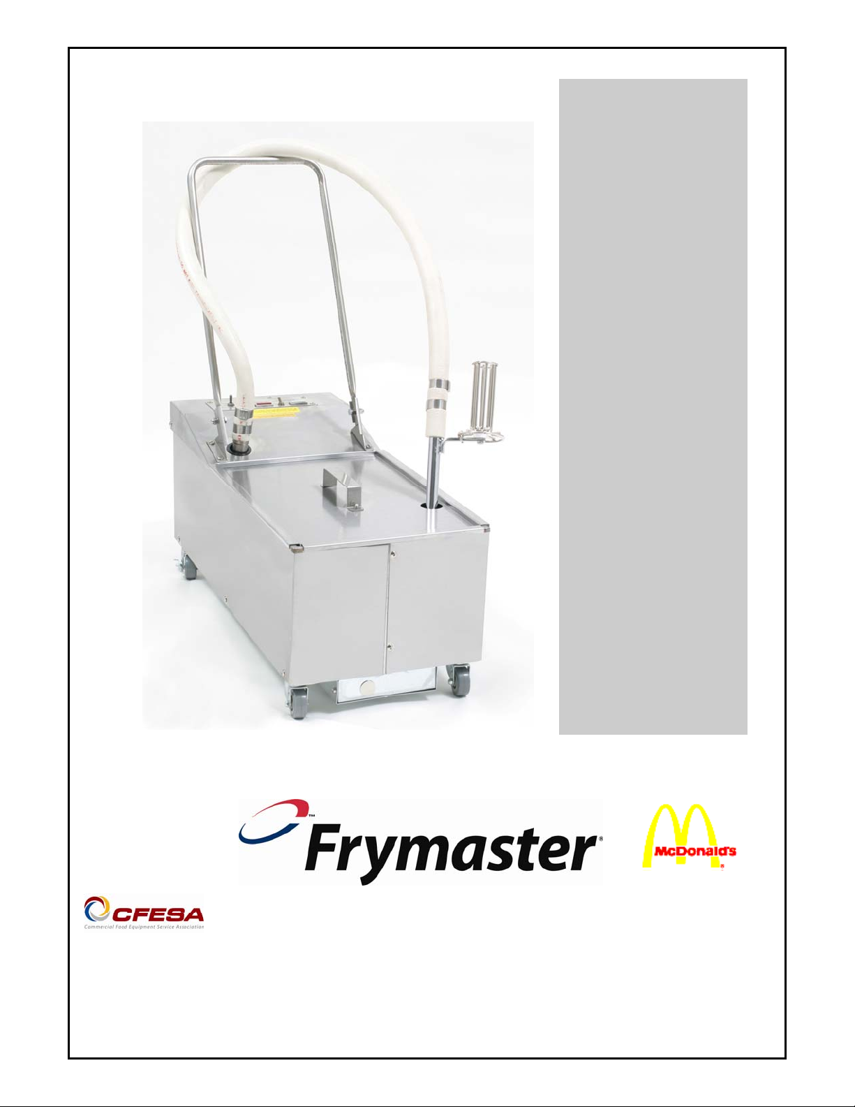
Operating, Service & Parts Manual
Filtration System
MPF50S Series Portable
Please read all sections of this manual and retain for future reference.
Frymaster, a member of the Commercial Food Equipment Service Association, recommends
using CFESA Certified Technicians.
24-Hour Service Hotline 1-800-551-8633
NOVEMBER 11
Page 2

Installation, maintenance, and repairs should be performed by your Frymaster Dean
Authorized Servicer.
WARNING
Safe and satisfactory operation of your equipment depends on its proper installation.
Installation MUST conform to local codes, or in the absence of local codes, with the
latest edition of the National Electric Code, N.F.P.A. 70.
WARNING
ELECTRICAL GROUNDING INSTRUCTIONS
This filter is equipped with a three-prong, grounded plug for your protection against
shock hazard and should be plugged directly into a properly grounded, three-hole
receptacle. Do not cut off, remove or otherwise bypass the grounding prong on this
plug.
If it is necessary to use an extension cord, it MUST be a three-conductor, grounded
cord of 16 gauge or greater.
DANGER
Do not filter more than one fry tank at a time.
Hot fluid – Do not fill above a point 1-½ inches below the OIL CONTAINER RIM.
WARNING
This filter unit is not suitable for outdoor use. When operating this unit, it MUST be
placed on a horizontal surface.
WARNING
This filter unit is not suitable for installation in an area where a water jet can be used,
and this appliance MUST NOT be cleaned with a water jet.
Page 3

NOTICE:
If this filter unit is cleaned with water, disconnect the unit from power source before
cleaning and thoroughly dry the filter unit before reconnecting to electrical power
source.
DANGER
The crumb tray (if equipped) in portable filter systems must be emptied into a fireproof
container at the end of frying operations each day. Some food particles can
spontaneously combust if left soaking in certain shortening material.
NOTICE:
Drawings and photos used in this manual are intended to illustrate operational, cleaning
and technical procedures and may not conform to on-site management operational
procedures.
NOTICE
IF, DURING THE WARRANTY PERIOD, THE CUSTOMER USES A PART FOR THIS
MANITOWOC FOOD SERVICE EQUIPMENT OTHER THAN AN UNMODIFIED NEW OR
RECYCLED PART PURCHASED DIRECTLY FROM FRYMASTER DEAN, OR ANY OF ITS
AUTHORIZED SERVICERS, AND/OR THE PART BEING USED IS MODIFIED FROM ITS
ORIGINAL CONFIGURATION, THIS WARRANTY WILL BE VOID. FURTHER,
FRYMASTER DEAN AND ITS AFFILIATES WILL NOT BE LIABLE FOR ANY CLAIMS,
DAMAGES OR EXPENSES INCURRED BY THE CUSTOMER WHICH ARISE DIRECTLY
OR INDIRECTLY, IN WHOLE OR IN PART, DUE TO THE INSTALLATION OF ANY
MODIFIED PART AND/OR PART RECEIVED FROM AN UNAUTHORIZED SERVICER.
Page 4

MPF50S Series Portable Filtration Systems
Operation, Service & Parts Manual
TABLE OF CONTENTS
Page #
1. INTRODUCTION 1-1
2. IMPORTANT INFORMATION 2-1
3. FILTER PREPARATION 3-1
4. OPERATING/FILTER INSTRUCTIONS 4-1
5. CLEANING AND MAINTENANCE 5-1
6. TROUBLESHOOTING/SERVICE PROCEDURES 6-1
7. PARTS LIST 7-1
Page 5

MPF50S SERIES PORTABLE FILTRATION SYSTEMS
CHAPTER 1: INTRODUCTION
1.1 Parts Ordering
Place parts orders directly with your local Frymaster/Dean Factory Authorized Servicer. A list of
Frymaster Factory Authorized Servicers (FAS’s) is located on the Frymaster website at
www.frymaster.com. If you do not have access to this list, please contact the Frymaster/Dean
service department at 1-800-551-8633 or 1-318-865-1711, or go to Frymaster/Dean’s website at:
www.frymaster.com.
To help speed your order, the following information is required:
Model Number Type
Serial Number
Optional Features
Item Part Number Quantity Needed
1.2 Service Information
Call the 1-800-551-8633 or (318) 865-1711 Service Hotline number for the location of your nearest
Factory Authorized Servicer. Always give the model and serial numbers of your filter unit. Also,
identify if your unit is supplied with or without a heater.
To assist you more efficiently, the following information will be needed:
Model Number Type
Serial Number
Optional Features
Nature of Problem:
Additional information (i.e. oil temperature at filter time, time of day and other pertinent
information) may be helpful in solving your service problem.
1-1
Page 6
MPF50S SERIES PORTABLE FILTRATION SYSTEMS
CHAPTER 1: INTRODUCTION
1.3 After Purchase
In order to improve service, fill out the following chart with the nearest Frymaster Authorized
Servicer and FAS in your area.
Factory Authorized
Servicer
Technician/FAS
Address
Telephone/Fax
Filter Model Number
Filter Serial Number
1.4 Safety Information
Before attempting to operate your unit, read the instructions in this manual thoroughly.
Throughout this manual, you will find notations enclosed in double-bordered boxes similar to the
ones below.
CAUTION
CAUTION boxes contain information about actions or conditions that may cause or result in a
malfunction of your system.
WARNING
WARNING boxes contain information about actions or conditions that may cause or result in
damage to your system, and which may cause your system to malfunction.
DANGER
DANGER boxes contain information about actions or conditions that may cause or result in injury
to personnel, and which may cause damage to your system and/or cause your system to malfunction.
1-2
Page 7

MPF50S SERIES PORTABLE FILTRATION SYSTEMS
CHAPTER 1: INTRODUCTION
1.5 Service Personnel
1.5.1 Definitions
A. Qualified and/or Authorized Operating Personnel
1. Qualified/authorized operating personnel are those who have carefully read the information
in this manual and have familiarized themselves with the equipment functions, or have had
previous experience with the operation of equipment covered in this manual.
B. Qualified Installation Personnel
1. Qualified installation personnel are individuals, or firms, corporations, or companies that,
either in person or through a representative, are engaged in and are responsible for the
installation of electrical appliances. Qualified personnel must be experienced in such work,
be familiar with all electrical precautions involved, and have complied with all requirements
of applicable national and local codes.
C. Qualified Service Personnel
1. Qualified service personnel are those who are familiar with Frymaster/Dean equipment and
have been authorized by Frymaster/Dean to perform service on Frymaster/Dean equipm ent.
All authorized service personnel are required to be equipped with a complete set of service
parts manuals and stock a minimum amount of parts for Frymaster/Dean equipment. A list
of Frymaster/Dean Factory Authorized Servicer’s (FAS’s) is located on the Frymaster
website at www.frymaster.com. Failure to use qualified service personnel will void the
Frymaster/Dean warranty on your equipment.
1.6 Warranty Statement
1. Frymaster L.L.C. warrants the MPF50S one year, parts and labor, against defects in material
and workmanship.
2. This warranty is void if equipment is found by Frymaster L.L.C. to have been subjected to
alteration, misuse, or abuse.
1-3
Page 8
MPF50S SERIES PORTABLE FILTRATION SYSTEMS
CHAPTER 2: IMPORTANT INFORMATION
2.1 General
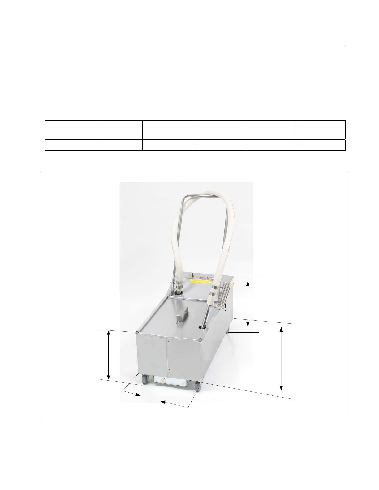
MPF50S portable filters can be used with a variety of Frymaster fryers, as well as other
manufacturers’ equipment. Oil capacity is approximately 50 pounds. Unit specifications are listed
below.
Model Unit Height
(inches)
MPF50S 13-¼ 13-¼ 30 11-¾ 50
Unit Width
(inches)
Unit Length
(inches)
Tank Height
(inches)
Oil Capacity
(pounds)
Unit
Height
Tank
Height
Unit
Width
Unit
Length
MPF50S Series portable filter dimensions.
2-1
Page 9
MPF50S SERIES PORTABLE FILTRATION SYSTEMS
CHAPTER 2: IMPORTANT INFORMATION
2.1 General (cont.)
Oil or shortening is gravity-drained from the fryer into the filter ("S" Models), or pumped from the
frypot into the filter pan, and then filtered through filter paper. Filter powder, which enhances the
filtering process, is distributed over the paper prior to filtering.
All units are shipped completely assembled with accessories packed inside the filter pan. All units
are adjusted, tested and inspected at the factory before shipment.
WARNING
The on-site supervisor is responsible for ensuring that operators are made aware of
the inherent dangers of operating a hot oil filter system, particularly the aspects of
oil filtration, and draining/cleaning procedures.
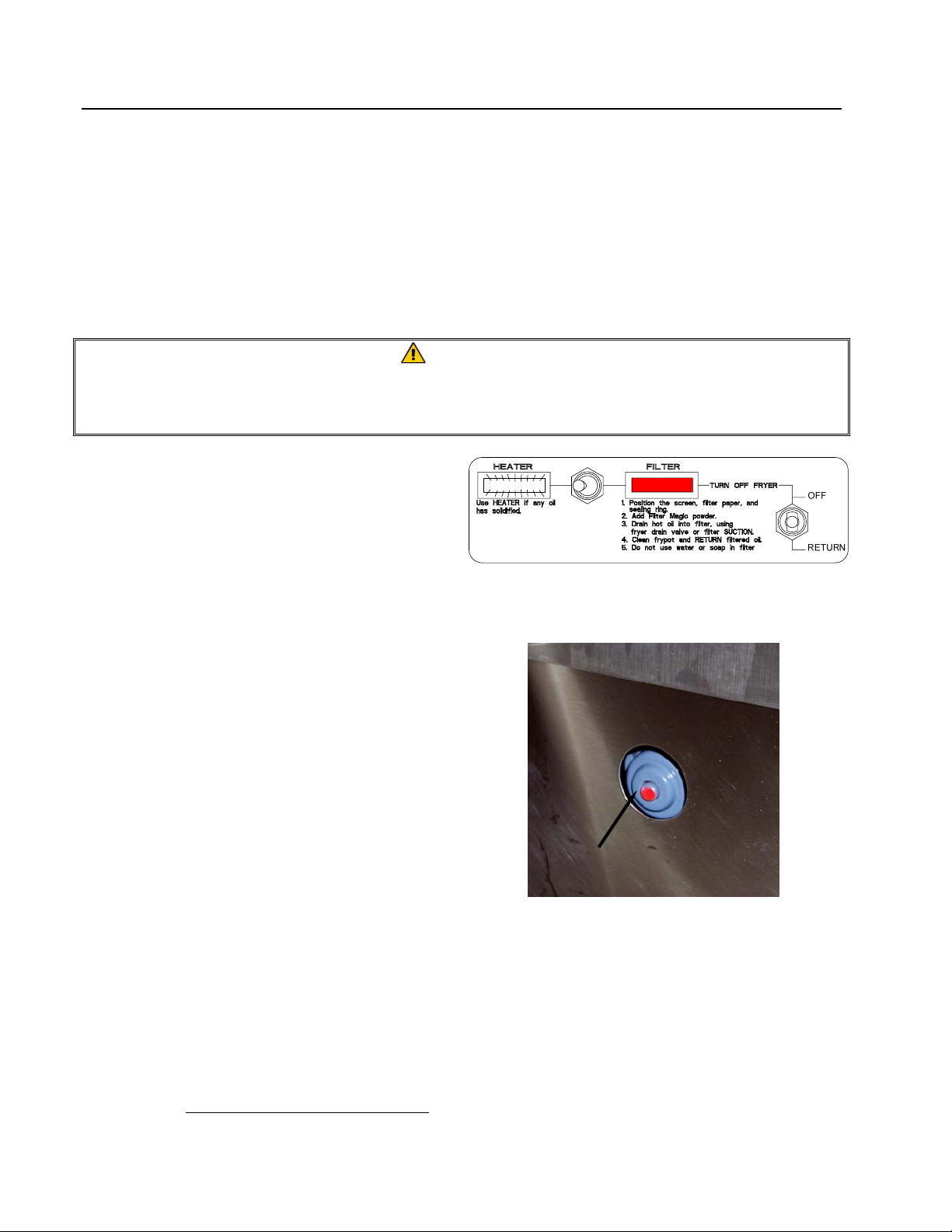
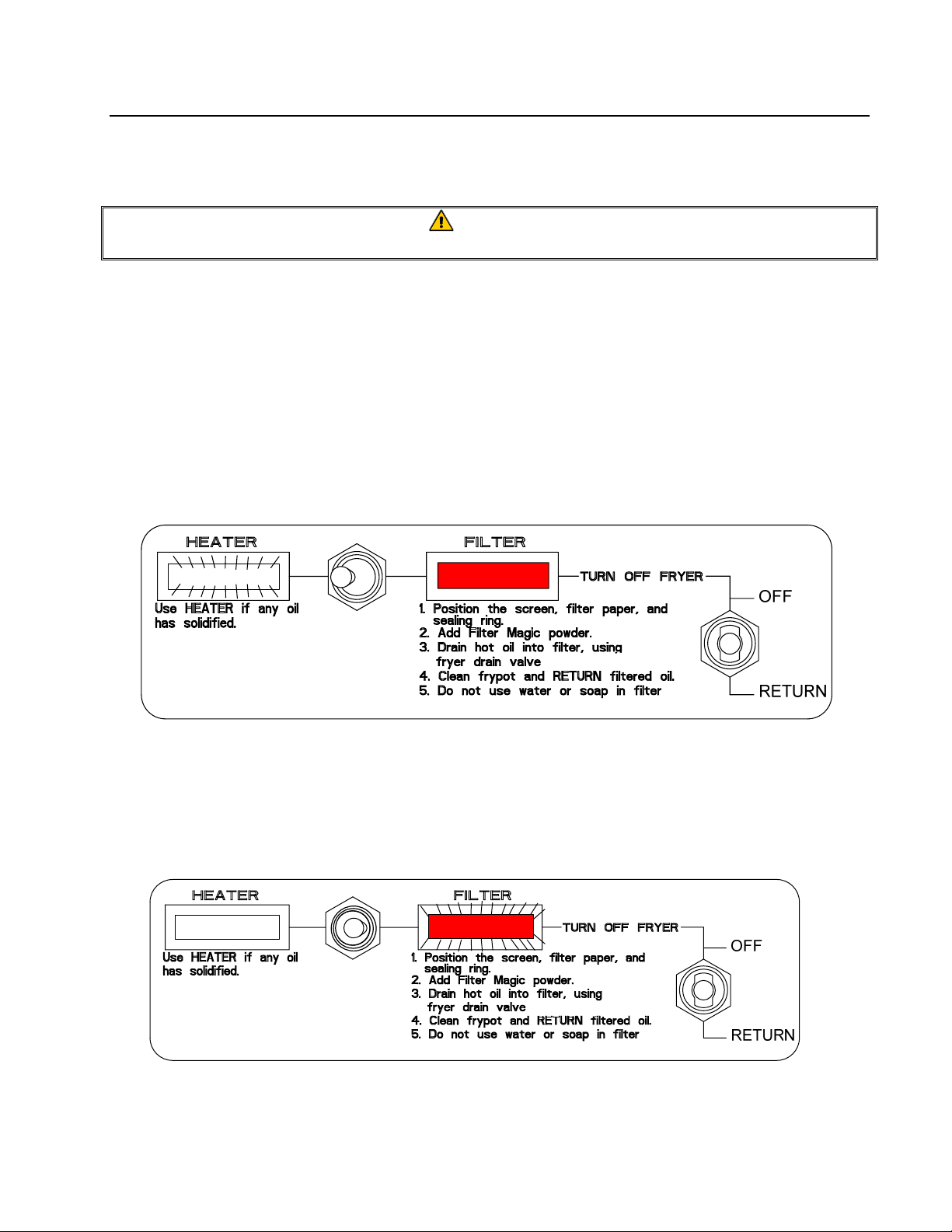
An Off/Return (MPF50S) switch
activates/deactivates the filter pump. The filter
also has a Heater/Filter switch for use when
filtering solid shortening.
A thermal-overload switch on the pump motor
MPF50S switch/light panel
provides protection against overheating.
NOTE: If the thermal overload is triggered,
wait 45 minutes, and then press the
reset button to activate the circuit after
the failure has been detected and
repaired.
The motor thermal overload switch (arrow) is
located on the left side of the filter.
2.2 Rating Plate
Information on the rating plate includes model and serial numbers, as well as electrical requirements.
The rating plate is located on the back housing, near the electrical receptacle. Have the rating plate
information handy when communicating with the factory about a unit or requesting special parts or
information. Without rating plate information, proper identification of the unit cannot be confirmed.
2-2
Page 10

MPF50S SERIES PORTABLE FILTRATION SYSTEMS
CHAPTER 2: IMPORTANT INFORMATION
2.3 Pre-Installation
NOTE: Failure to use qualified service personnel will void the Frymaster warranty.
A. Standards
: Use of this filter unit must be in accordance with all applicable state and local
codes.
DANGER
This portable filter is equipped with a three-prong (grounding) plug for protection
against electrical shock and must be plugged directly into a properly grounded,
three-prong receptacle. DO NOT CUT, REMOVE, OR OTHERWISE BYPASS THE
GROUNDING PRONG ON THIS PLUG!
B. Electrical Connections: Domestic MPF50S filter units require 115V 60 Hz., 15 amp
electrical supply. International/CE units require 230V 50 Hz., 7 amp electrical supply. Units
are equipped with a grounded male receptacle for use with a 16-3 SJT power cord set. If an
extension cord is required, it must be a three-conductor, grounded power cord of at least 16
gauge.
2.4 Unpacking the Filter System
Ensure the container is upright. Unpack the filter carefully and remove all accessories from the
carton. Do not discard or misplace parts and/or accessories; they will be needed for filter setup
and operation. Any accessories or starter kits included with the unit will be packaged inside
the filter tank.
After unpacking, immediately check the equipment for visible signs of shipping damage. If
such damage has occurred, contact the carrier and file the appropriate freight claims. Do not
contact the factory, as the responsibility of shipping damage is between the carrier and dealer
or end-user.
If your equipment arrives damaged:
a. File claim for damages immediately – Regardless of extent of damage.
b. Visible loss or damage – Be sure this is noted on the freight bill or express receipt and is
signed by the person making the delivery.
c. Concealed loss or damage – If damage is unnoticed until equipment is unpacked, notify
freight company or carrier immediately, and file a concealed damage claim. This should be
done within 15 days of date of delivery. Retain the shipping container for inspection.
NOTE: Frymaster does not assume responsibility for damage or loss incurred in transit.
2-3
Page 11

MPF50S SERIES PORTABLE FILTRATION SYSTEMS
CHAPTER 3: FILTER PREPARATION
3.1 Assembling The Filter System
On initial installation and before each use, remove all loose parts from the filter, wash all accessories
in hot, soapy water and dry thoroughly. DO NOT WASH INTERIOR OF FILTER PAN WITH
DETERGENT OR WATER! Wipe debris and residue from the filter pan with a damp cloth or
paper towel, then with a dry cloth or paper towel.
WARNING!
Water, detergent or boil-out solution MUST NOT be allowed into the filter pan or
filter system. Irreversible pump damage will result if water is allowed into the
system, and the warranty will be voided.
MPF50S Series portable filtration systems use a filter support grid, one sheet of filter paper and a
hold-down ring to secure the filter paper in place.
See illustration for proper assembly.
1. Filter Pan Cover
2. Hold-Down Ring
3. Filter Paper (one sheet)
4. Screen/Support Grid
5. Filter Pan
3-1
Page 12

MPF50S SERIES PORTABLE FILTRATION SYSTEMS
CHAPTER 3: FILTER PREPARATION
3.1 Assembling The Filter System
1. Ensure the filter pan is clean and free of all food and breading particles that could prevent the
filter paper from sealing against the bottom of the pan.
2. Place the filter paper support screen between the raised dimples in the bottom of the pan.
3. Place one sheet of filter paper on top of the support screen. Ensure the paper evenly covers the
filter pan bottom.
4. Position the hold-down ring on top of the filter paper and ensure the filter paper overlaps all
sides of the hold-down ring, forming a tight seal.
5. Place filter pan cover onto the filter pan and assembly is complete.
3-2
Page 13
MPF50S SERIES PORTABLE FILTRATION SYSTEMS
CHAPTER 4: OPERATING/FILTERING INSTRUCTIONS
4.1 Filter Operation
WARNING
Use care when draining and filtering oil to avoid the possibility of a serious burn.
1. Sprinkle 8 ounces (1 cup) of filter powder over the filter paper, distributing the powder as evenly
as possible. If filtering a second frypot immediately after the first, add only 4 ounces of filter
powder for the second filtering.
2. Ensure the power cord is securely plugged into the receptacle on the back of the portable filter.
Plug the power cord into an 115V outlet.
3. If solid shortening is filtered through the portable filter, turn the Heater/Filter switch to HEATER
(see illustration below). The white indicator light will illuminate. Leave the heater on for 20-30
minutes before operating the filter.
Note: The filter pump cannot be activated while the switch is in the "Heater" position.
4. Ensure the Off/Return switch is OFF. Turn the Heater/Filter switch to FILTER for filter
operation (see illustration below). The red indicator light will illuminate.
Use the filter heater for 20-30 minutes prior to filtering if solid shortening is filtered.
The Heater/Filter switch must be in the FILTER position before the filter pump can
be operated. The red light will illuminate when the switch is properly positioned.
4-1
Page 14

MPF50S SERIES PORTABLE FILTRATION SYSTEMS
CHAPTER 4: OPERATING/FILTERING INSTRUCTIONS
4.1 Filter Operation (cont.)
5. Ensure the oil is at operating temperature, 350°F (177°C). Turn the fryer off.
WARNING
The filter pan maximum capacity is 50 lbs. DO NOT OVERFILL THE FILTER PAN.
6. Place filter pan directly under fryer drain valve and drain oil into the filter. Place the filter hose
nozzle inside the frypot. Turn the Off/Return to RETURN to start the filter pump (see
illustration below).
Allow the oil to circulate through the frypot and filter for approximately 5 minutes
(process known as "polishing"). Polishing the oil produces maximum filtration and
extends the life of the oil. Rinse any residual oil or sediment from the frypot during the
polishing process.
Close the drain valve and return the filtered oil to the frypot. Ensure all oil is returned to
the frypot before turning filter off.
Allow the portable filter to cool, then remove and discard the filter paper. Clean the
interior of the filter pan and all components. Do not use detergent or water in the filter
pan for cleaning.
See Chapter 5 for preventive maintenance/cleaning procedures.
4-2
Page 15

MPF50S SERIES PORTABLE FILTRATION SYSTEMS
CHAPTER 5: CLEANING AND MAINTENANCE
5.1 General
Cleaning operations fall into three general categories:
• Wiping unit clean after each filter session;
• Cleaning, changing filter paper and preparing the unit for the next day’s business.
• Weekly cleaning to remove oil deposits and other particles.
WARNING
Do not use water jets to clean this equipment. To do so will damage the unit and
void the warranty.
WARNING
Never operate the filter unit unless cooking oil is at operating temperature.
5.2 Each Filter Use
Each time the MPF50S portable filter is used:
• Wash down the insides of the filter pan with hot oil during the filtering process. DO NOT
allow excessive residue buildup to occur inside the filter pan.
• Change filter paper after each filter session or at the end of the day. Scrape excess sediment
from filter paper after each frypot is filtered within a filter session. If oil is not returned to the
frypot within 7 minutes, the filter paper may be clogged. Change filter paper if this occurs.
• Wipe up any oil which may have splashed or spilled.
• Wipe all exterior surfaces of the filter unit.
WARNING
Do not run water or boil-out solution through the portable filter. Doing so will cause
irreparable damage to the pump, and void the warranty.
5-1
Page 16

MPF50S SERIES PORTABLE FILTRATION SYSTEMS
CHAPTER 5: CLEANING AND MAINTENANCE
5.3 Daily— Close Of Business
At the close of a working day, filter the oil in all fryers. When the last fryer is filtered, follow these
steps:
1. Ensure the flexible hose and pump lines are clear by running the filter pump for an
additional 15–30 seconds after air bubbles start coming from the oil return line. Drain the
flexible hose as much as possible, especially if solid shortening is used.
2. Remove the filter pan cover and hold-down ring, and then remove the filter paper and filter
paper support screen.
3. Discard filter paper.
4. Wash all filter components with hot soapy water and rinse. DO NOT use soap and/or water
inside the filter pan. Wipe residual oil and sediment from inside the filter pan with a clean
cloth or paper towel.
5. Rinse all parts with clean water (except filter pan interior), and then dry all filter parts
thoroughly before reassembling.
6. Check the hose fitting on the pump and ensure that it is tight. Check plumbing for leaks.
See Chapter 6 for service procedures. Check plumbing for leaks.
5.4 Weekly
Follow the same procedure as for "Daily", with these additional steps:
• Clean built-up residue and debris from filter pan by wiping with a clean cloth or paper
towel. DO NOT use soap and/or water inside the filter pan. Ensure all components fit
properly and function correctly.
• Clean thoroughly under, around, and behind the fryers and filtering area with hot soapy
water and rinse.
• Check the hose connection and tighten if hose becomes loose and starts to leak oil.
5-2
Page 17

MPF50S SERIES PORTABLE FILTRATION SYSTEMS
CHAPTER 6: TROUBLESHOOTING/SERVICE PROCEDURES
6.1 Operating Problems
Plugged lines and plugged filter paper account for over 90 percent of filtration system malfunctions.
A general troubleshooting chart, included in this chapter, provides instructions in diagnosing
common malfunctions. Contact a factory-authorized service technician for troubleshooting beyond
the scope of the operator.
A. Plugged Lines
1. To guard against plugged lines when using solid shortening, follow these guidelines:
a. Turn the Heater/Filter switch to HEATER and allow the heater to remain on for 20-30
minutes before attempting a filter cycle.
b. At the end of the filtering cycle, let the filter bubble into the fryer through the flexible
hose for about 15-30 seconds. If it is blowing bubbles, air is moving through the lines
and the filter is less likely to be plugged.
c. When filtering is complete, drain oil or shortening from the hose.
B. Plugged Paper
Improper use of the filter powder will cause a slow oil flow return rate. The first indication of paper
plugging is a surging, jerking movement of the hose. To correct this, review the instructions for the
correct use of filter powder, and change the filter paper more frequently. When filtering several
fryers prior to changing paper, ensure that excess sediment is scraped off the filter paper after
filtering each frypot.
6.2 General Troubleshooting
The following chart contains information to assist in diagnosing the most common malfunctions
with portable filtration systems. Possible solutions and/or corrective actions are given for each
scenario.
If the malfunction cannot be diagnosed using the information in this section, contact your Factory
Authorized Service Agent for repairs.
DANGER
Use extreme care when testing electrical circuits. Live circuits will be exposed.
DANGER
Inspection, testing and repair of gas or electrical equipment should be performed by
qualified personnel.
6-1
Page 18

MPF50S SERIES PORTABLE FILTRATION SYSTEMS
CHAPTER 6: TROUBLESHOOTING/SERVICE PROCEDURES
6.2 General Troubleshooting (cont.)
Pump won't
start.
Pump stops
during
filtering
process.
Pump starts
and abruptly
stops.
Tripped thermal overload switch.
Incorrect or no line voltage.
Filter heater switch in the Heat position.
Allow filter unit to cool for at least 45 minutes and
then press (reset) the motor thermal overload
switch.
Turn filter pump "OFF". Allow oil to cool then empty
pan. Verify filter paper is clean and properly
installed. Refill pan and restart process.
Reset thermal overload switch.
Pump is blocked or wiring is loose. Call FAS for
service.
Motor failed; call FAS for service.
Pumping is
erratic.
Oil not being
returned to
frypot.
Verify that filter paper is properly installed under
hold-down ring.
Verify that filter hose connection is tight and secure.
The filter hose is clogged with debris. Clear hose.
Clogged filter paper. Scrape off excess sediment
or replace filter paper.
Filter pan suction tube is blocked. Use a thin,
flexible wire to unclog.
6-2
Page 19

MPF50S SERIES PORTABLE FILTRATION SYSTEMS
CHAPTER 6: TROUBLESHOOTING/SERVICE PROCEDURES
6.3 Wiring Diagrams
6.3.1 MPF50SS 115
PUMP MOTOR
CONTROL SWITCH
1P
11P
12P
PUMP
MOTOR
FILTER
LIGHT
3P
FILTER
SWITCH
4P
HEATER
LIGHT
15P
HEATER
16P
2P
14P
BLACK
17P
BLACK
6.3.2 MPF50S/MPF50SS 115/230V Pump Motor Wiring
BLK #5
*
L1
YEL 9P
WHITE
GREEN
WHITE
GREEN
EXTERNAL
CORD
CORDSET
115V OPTION
230V OPTION
3
4
WHT 11P
BRN 12P
(PF50)
BLK 13P
BRN 12P
RED #8
L2
*
(PF50S)
BLU 10P
* DENOTES BOMBTAIL
115/230V MOTOR WIRING
6-3
Page 20

MPF50S SERIES PORTABLE FILTRATION SYSTEMS
CHAPTER 6: TROUBLESHOOTING/SERVICE PROCEDURES
6.4 Service Procedures
6.4.1 Replace Lights/Switches
WARNING
Disconnect power cord from electrical power before servicing.
1. Disconnect power cord from power supply.
2. Remove four screws securing the switch
panel to the control panel.
3. Lift the panel out of the control panel to
access wiring.
4. Mark the wire locations on the defective
switch/light and disconnect the wiring.
5. Install new switch or light, connect the wiring
and install the switch panel. Replace the
screws removed in Step 1.
Remove screws (arrows) securing switch panel
to the control panel.
Mark wiring locations on defective switch/light
before disconnecting wires.
6-4
Page 21

MPF50S SERIES PORTABLE FILTRATION SYSTEMS
(
CHAPTER 6: TROUBLESHOOTING/SERVICE PROCEDURES
6.4.2 Replace Heater Strip
1. Disconnect power cord from power supply.
2. Perform Step 2, Section 6.4.3.1, Replace
Motor.
3. Remove screws securing outer panels and
cord-holding bracket. Remove bracket and
the panels.
4. Turn the unit on its side and remove four nuts
securing the filter pan to the base assembly.
Carefully pull the filter pan away from the
base to gain access to heater strip. Use care
not to damage the flexlines connecting the
pan to the pump.
5. Remove foil-insulating tape securing the
heater strip to the pickup tube. Remove the
heater strip from the pickup tube.
6. Remove the remainder of the foil-insulating
tape from the flexline(s) and the pump, and
then remove the heater strip. Note routing of
the heater strip on the pump and flexline(s)
prior to heater strip removal.
Remove screws securing outer panels.
Remove four nuts securing filter pan to base
arrows).
Remove foil-insulating tape to expose heater
strip (arrow).
6-5
Page 22

MPF50S SERIES PORTABLE FILTRATION SYSTEMS
CHAPTER 6: TROUBLESHOOTING/SERVICE PROCEDURES
6.4.2 Replace Heater Strip (cont.)
7. 115VAC Filters: Disconnect the black wire
from the heater indicator light on the switch
panel (left, black arrow), and the white wire
from the receptacle (white, white arrow).
230VAC Filters: Disconnect the red wire
connected to the power supply cord (bombtail
connection) and the violet wire connected to
the Heater Indicator light on the switch panel.
8. Starting at the sump on the pan bottom,
install the new heater strip, using foil tape to
secure the heater to the pickup tube (see Step
3, this section).
9. Route the heater strip over the plumbing and
around the pump as previously removed in
Step 4.
10. Complete installation by securing strip with
foil tape. Reconnect the wire connections
disconnected in Step 7, this section.
Reassemble filter by reversing Steps 1-3, this
section.
Heater strip wiring connections at switch panel
and receptacle (115V heater strip shown).
6-6
Page 23
MPF50S SERIES PORTABLE FILTRATION SYSTEMS
CHAPTER 6: TROUBLESHOOTING/SERVICE PROCEDURES
6.4.3 Replace Motor/Pump
1. Disconnect power cord from power supply.
2. Perform Step 2, Section 6.4.1. Remove two
screws securing the handle brackets to the
control panel (arrows). Do not remove the
remaining handle-bracket screws. Remove
remaining screws securing control panel to
filter base. Lift the control panel from the
base and work the switch panel through the
control panel opening. Leave the switch
panel wired and set aside, using care not to
stretch and disconnect wiring. Remove
control panel.
3. Remove cord-holder bracket and outer panels
(see Step 3, Section 6.4.2 for reference).
Remove these
screws from handle
brackets to remove
control panel.
Remove screws illustrated to remove control
panel. (Switch panel omitted for clarity.)
Remove cord-holder bracket and outer panels.
6-7
Page 24

MPF50S SERIES PORTABLE FILTRATION SYSTEMS
CHAPTER 6: TROUBLESHOOTING/SERVICE PROCEDURES
6.4.3.1 Replace Motor
4. Remove four bolts securing the pump to the
motor. Leave the plumbing connected to the
pump. Use care not to damage the flex
supply lines connected to the pump. Remove
the pump gasket for reassembly.
5. Remove six screws securing the motor
bracket from the bottom of the base. Support
the motor with one hand when removing the
screws. Pull the motor/motor-bracket out of
the cabinet and set on floor. Use care not to
damage the motor wiring. Remove four bolts
securing the motor to the motor-bracket.
Place the replacement motor next to the old
motor for ease of rewiring.
6. Remove the cover plate to access the motor
wiring. Splices or bombtails are needed for
two connections. Rewire the replacement
motor using the wiring diagram in Section
6.3.4.
7. Complete installation of replacement motor
by reversing the above steps.
Remove six screws from the base bottom to remove
the motor and motor bracket. Remove four bolts
securing the motor to motor-bracket after removing
the bracket from the base.
Two connections require splices or bombtails
(arrows).
.
6-8
Page 25

MPF50S SERIES PORTABLE FILTRATION SYSTEMS
CHAPTER 6: TROUBLESHOOTING/SERVICE PROCEDURES
6.4.3.2 Replace Pump
1. Disconnect power cord from power supply.
2. Perform Steps 2 and 3, Section 6.4.3.1,
Replace Motor.
3. Remove foil insulation tape and heater strip
from pump and flex lines. Remove the heater
strip from the pump and disconnect flexlines
from the check valve connections.
4. Remove pipefittings from pump before
removing pump from motor.
5. Remove four bolts securing the pump to the
motor. Remove the pump and pump gasket.
Fit new pump gasket and install new pump on
motor. Torque pump bolts to 15-foot pounds.
Do not over-tighten the bolts.
6. Reinstall all removed components during
pump removal by reversing the above steps.
Remove foil insulation tape covering the heater
strip and remove heater strip from the pump and
flexlines.
Remove four bolts securing the pump to the
motor. Remove pump and gasket from motor.
6-9
Page 26
MPF50S SERIES PORTABLE FILTRATION SYSTEMS
CHAPTER 6: TROUBLESHOOTING/SERVICE PROCEDURES
6.4.3.3 Replace Wand Hose
1. Disconnect power cord from power supply.
2. Remove cord-holder bracket and outer panels
(see Step 3, Section 6.4.2 for reference).
3. Unscrew the hose fitting with an open-end
wrench from the elbow on the pump.
4. Install the new hose, using care not to cross-
thread the connections. Use an approved pipe
sealant on the threads to ensure a leak-proof
connection. DO NOT OVER-TIGHTEN
THE CONNECTION.
5. Replace the outer panels and the cord-holder
bracket.
Remove cord-holder bracket and outer panels.
Remove hose fitting (arrow) with an open-end
wrench. Use pipe sealant when installing new
hose.
6-10
Page 27
MPF50S SERIES PORTABLE FILTRATION SYSTEMS
CHAPTER 7: PARTS LIST
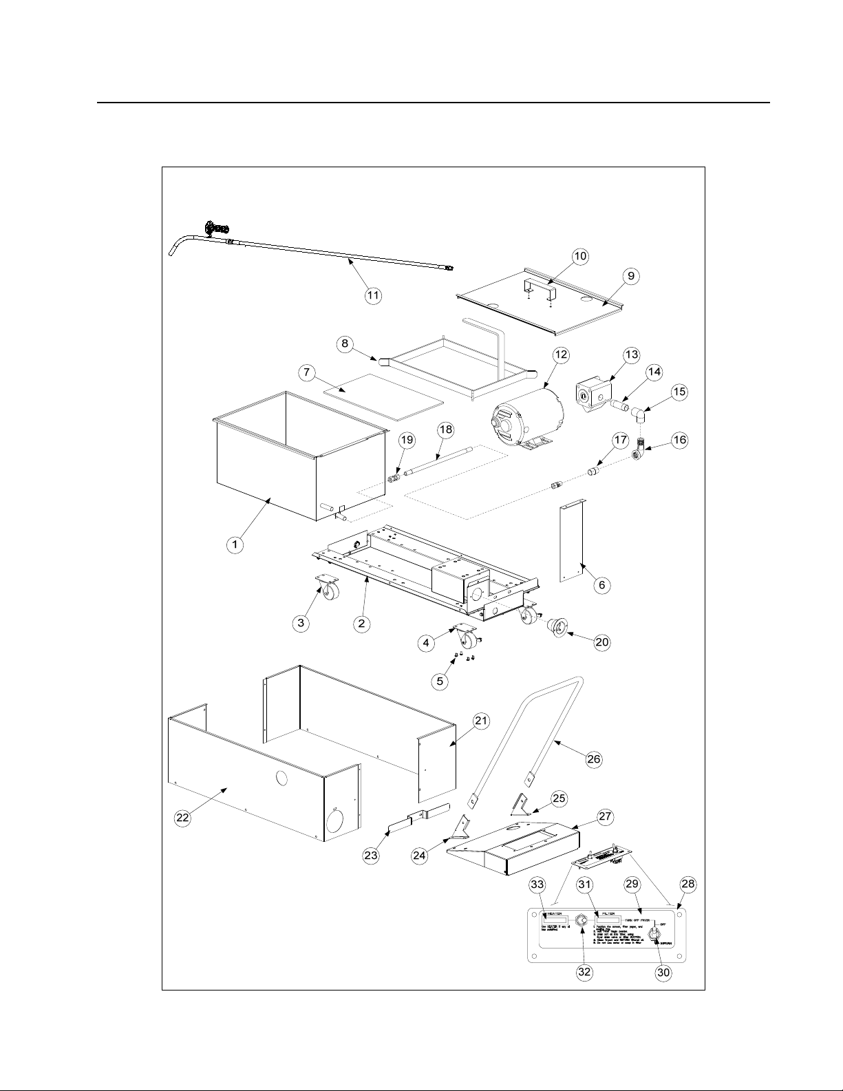
7.1 MPF50S Parts List
7-1
Page 28

MPF50S SERIES PORTABLE FILTRATION SYSTEMS
CHAPTER 7: PARTS LIST
Item Part # Description
1 823-6231 Pan, Filter
806-
2
5223SP
900-9542 Bracket, Motor-Mount – All MPF50S
900-1748 Brace, End- Filter Base
900-8585 Brace, Rear Cross- Filter Base
3 810-2805 Caster, 2"- Swivel (Without Brake)
4 810-2806 Caster, 2"- Swivel (With Brake)
5 809-0475 Screw- 10-32 x 5/16 Hex
6 900-3751 Bracket, Standoff
7 900-8825 Screen, Filter Paper Support
* 803-0003 Paper, Filter 17 ¾” x 12 ½” 100 sheets
* 803-0002 Powder, Filter, 80 packets
8 823-0889 Ring, Hold-down
9 230-2836 Lid, Filter Pan
* 823-5950 Crumb basket
10 810-3162 Handle, Pan Lid 802-
* 826-1379 Screw, #10 x ½" Phillips (Lid Handle) (Qty. of 10)
* 809-0184 Washer, Lock - #10 (Lid Handle)
* 809-0020 Nut, Cap- 10-24 (Lid Handle)
11 106-7847 Complete Hose/wand assembly
* 810-3303 Hose
12
826-1712 115V 60HZ 1/3 HP (Includes Motor and Gasket)
826-1270 230/240V 50/60HZ 1/3 HP (Includes Motor and Gasket)
13 826-1264 Pump, Filter - 4GPM (Includes Pump and Gasket)
14 813-0265 Nipple, ½ x 2-½" NPT BM
15 813-0062 Elbow, ½" NPT BM
* 806-3844 Heater Strip, 120V 40W
* 806-7435 Heater Strip, 230/240V 70W
16 813-0165 Elbow, Street- ½" NPT BM
17 813-0022 Nipple, ½" x Close NPT BM
18 810-1435 Flexline, ½ x 12" S/S Hose
19 813-0545 Union, ½ x ½" Flexline Hose
20 807-1219 Receptacle, 115V 3-Wire (120V Domestic Units Only)
* 807-1224 Cord, Power - 3-Wire 115V
* 807-4317 Cord, Power – Euro 3-Wire 230/240V
21 910-8587 Panel, Outer - Left Side
22 910-8586 Panel, Outer - Right Side
Base Assembly (Includes items 3 & 4)
Motor, Filter Pump
7-2
Page 29

MPF50S SERIES PORTABLE FILTRATION SYSTEMS
CHAPTER 7: PARTS LIST
23 910-3788 Holder, Power Cord
24 912-2616 Bracket, Handle- Right
25 911-2616 Bracket, Handle- Left
* 826-1380 Screw, ¼-20 x ½" Slotted Head (For Handle Bracket) (Qty. of 5)
26 910-9169 Handle, Portable Filter
* 826-1389 Bolt, ¼-20 x ¾" Hex Head (Qty. of 10)
* 810-0219 Spacer, Handle Bolt
* 809-0047 Nut, Cap- ¼-20 High Profile S/S
27 824-0403 Panel, Control
28 910-0982 Panel, Switch
29 802-1438 Label, Switch Plate
30 807-1041 Switch, Toggle, Off-Return
31 807-1060 Light, Indicator- Red Lens (Filter Indicator Light) 120V
807-1086 Light, Indicator- White Lens (Filter Indicator Light) 230/240V (Europe Only)
32 807-1041 Switch, Toggle- 2-Way SPDT - All PF50
33 807-1061 Light, Indicator- White Lens (Heater Indicator Light) 120V
807-1086 Light, Indicator- White Lens (Heater Indicator Light) 230/240V (Europe Only)
* Not Illustrated
7-3
Page 30

A
Frymaster, L.L.C., 8700 Line Avenue, Shreveport, Louisiana 71106
TEL 1-318-865-1711 FAX (Parts) 1-318-219-7140 FAX (Tech Support) 1-318-219-7135
PRINTED IN THE UNITED STATES
SERVICE HOTLINE
1-800-551-8633
819-6301
NOVEMBER 11
 Loading...