

Page 1
*8196791
A
*
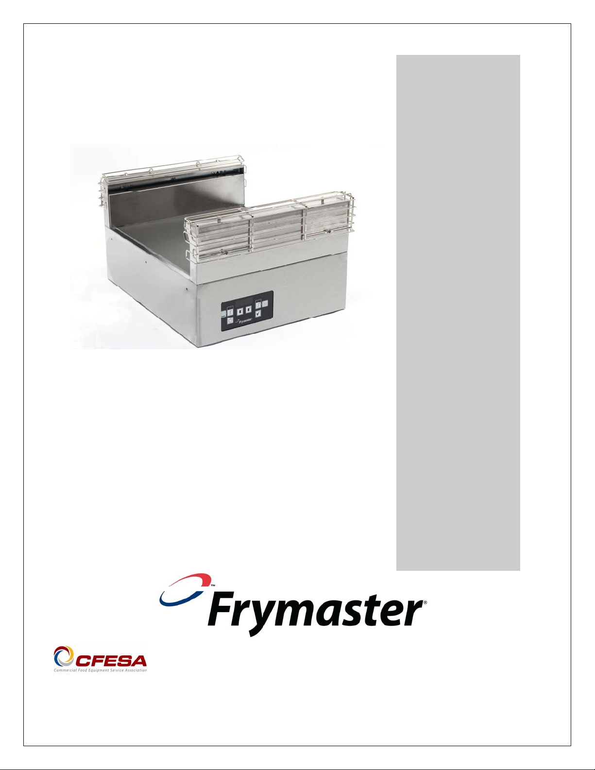
Heated Landing Area
Installation, Operating Manual
Frymaster, a member of the Commercial Food Equipment Service Association, recommends
using CFESA Certified Technicians.
24-Hour Service Hotline 1-800-551-8633
Email: service@frymaster.com
Price: $6.00
819-6791A
FEB 12
Page 2
NOTICE
IF, DURING THE WARRANTY PERIOD, THE CUSTOMER USES A PART FOR THIS MANITOWOC
FOOD SERVICE EQUIPMENT OTHER THAN AN UNMODIFIED NEW OR RECYCLED PART
PURCHASED DIRECTLY FROM FRYMASTER/DEAN, OR ANY OF ITS AUTHORIZED SERVICE
CENTERS, AND/OR THE PART BEING USED IS MODIFIED FROM ITS ORIGINAL
CONFIGURATION, THIS WARRANTY WILL BE VOID. FURTHER, FRYMASTER/DEAN AND ITS
AFFILIATES WILL NOT BE LIABLE FOR ANY CLAIMS, DAMAGES OR EXPENSES INCURRED BY
THE CUSTOMER WHICH ARISE DIRECTLY OR INDIRECTLY, IN WHOLE OR IN PART, DUE TO
THE INSTALLATION OF ANY MODIFIED PART AND/OR PART RECEIVED FROM AN
UNAUTHORIZED SERVICER.
THE HLA IS NOT SUITABLE FOR OUTDOOR USE. WHEN OPERATING THIS UNIT, IT MUST
BE PLACED ON A HORIZONTAL SURFACE.
THE HLA IS NOT SUITABLE FOR INSTALLATION IN AN AREA WHERE A WATER JET CAN
BE USED. THIS APPLIANCE MUST NOT BE CLEANED WITH A WATER JET.
CAUTION – RISK OF FIRE/SHOCK. DO NOT RESTRICT VENTILATION OPENINGS ON
BOTTOM OF UNIT DURING INSTALLATION.
DO NOT POSITION THE HLA’S AIR INTAKE VENT NEAR THE STEAM OR HEAT EXHAUST OF
ANOTHER APPLIANCE.
FOR YOUR SAFETY
DO NOT STORE OR USE GASOLINE OR OTHER FLAMMABLE VAPORS AND LIQUIDS IN
THE VICINITY OF THIS OR ANY OTHER APPLIANCE.
DO NOT OPERATE OR SERVICE THE HLA WITHOUT FIRST READING THIS MANUAL.
DO NOT OPERATE THE HLA UNLESS IT HAS BEEN PROPERLY INSTALLED AND CHECKED.
DO NOT OPERATE THE HLA UNLESS ALL SERVICE AND ACCESS PANELS ARE IN PLACE
AND PROPERLY SECURED.
DO NOT ATTEMPT TO REPAIR OR REPLACE ANY COMPONENT OF THE HLA UNLESS ALL
POWER TO THE UNIT HAS BEEN DISCONNECTED.
USE CAUTION WHEN SETTING UP, OPERATING, OR CLEANING THE HLA TO AVOID
CONTACT WITH HEATED SURFACES.
Page 3
HLA
Table of Contents
Chapter Page
Warranty 1-1
Service Information 2-1
Installation, Operation 3-1
Annotated Overview 4-1
Controller 5-1
Troubleshooting 6-1
Cleaning 7-1
Page 4

HLA
1: Warranty
The Frymaster Corporation makes the following limited warranties to the original purchaser only for this
equipment and its replacement parts:
1.1 Warranty Provisions – Heated Landing Area (HLA)
A. The Frymaster Corporation warrants all components against defects in material and workmanship for a period
of 2 years.
B. All parts, with the exception of fuses, are warranted for 2 years after installation date of cabinet.
C. If any parts become defective during the first 2 years after installation date, Frymaster will also pay straight-
time labor costs to replace the part, plus up to 100 miles/160 km of travel (50 miles/80 km each way).
1.2 Parts Return
All defective in-warranty parts must be returned to a Frymaster Authorized Factory Service Center within 60 days
for credit. After 60 days, no credit will be allowed.
1.3 Warranty Exclusions
This warranty does not cover equipment that has been damaged due to misuse, abuse, alteration, or accident
such as:
• improper or unauthorized repair;
• failure to follow proper installation instructions and/or scheduled maintenance procedures as prescribed in
your MRC cards;
• improper maintenance;
• damage in shipment;
• abnormal use;
• removal, alteration, or obliteration of the rating plate;
This warranty also does not cover:
• transportation or travel over 100 miles/160 km (50 miles/80 km each way), or travel time over two (2)
hours;
• overtime or holiday charges;
• consequential damages (the cost of repairing or replacing other property which is damaged), loss of time,
profits, use or any other incidental damages of any kind.
There are no implied warranties or merchantability or fitness for any particular use or purpose.
For international warranty, the above procedures apply, except that the customer is responsible for freight and
duty charges.
1-1
Page 5

HLA
2: Service Information
2.1 Ordering Parts
Parts orders may be placed directly with your local Frymaster Factory Authorized Servicer (FAS) or distributor. A
list of Frymaster FAS’s is available at WWW.frymaster.com
contact the Frymaster Service Department at 1-800-24-FRYER or 1-318-865-1711.
To speed up your order, the following information is required:
Model Number ______________________
Serial Number ______________________
Voltage ___________________________
Item Part Number ___________________
Quantity Needed ____________________
2.2 Service Information
Service may be obtained by contacting your local Frymaster Authorized Servicer. Service information may be
obtained by calling the Frymaster Service Department. The following information will be needed in order to assist
you quickly and efficiently:
Model Number _________________________
Serial Number _________________________
Nature of the Problem ___________________
_____________________________________
_____________________________________
_____________________________________
Additional information (i.e. cooking environment, time of day) may be helpful in solving your service
problem. Contact your service technician.
RETAIN AND STORE THIS MANUAL IN THE EQUIPMENT MANUAL FOR FUTURE USE.
. If you do not have internet access to this list, please
2-1
Page 6

HLA
3: Installation, Operation
Upon arrival, inspect the HLA for concealed damage. Immediately report any damage to the delivering
freight company. Claims must be filed within 15 days after receipt of the unit.
1. The HLA must be installed in a KES-provided Modular Order Assembly Table (M.O.A.T.).
2. The controller is accessible behind a removable module of the assemble table.
Heated Landing Area (HLA)/Order Assembly Table (OAT) Installation Instructions
The process outlined below must be used to secure the Frymaster HLA to the KES OAT. The
HLA was designed specifically to operate as a component of McDonald’s Order Assembly
Table and failure to properly install the unit could lead to unsatisfactory operation/product
malfunction.
1. Remove three screws from each side
of the HLA (see photo below). Retain the
screws.
2. Ensure that the Order Assembly Table
(OAT) mounting area (see drawing,
right) is free of obstructions or debris.
3. Place the plug of the HLA through the
opening on the top of the OAT Core,
being sure not to pinch the cord.
4. Place the side of the HLA flush with the
front module. The three holes in the front
module should line up with the three
holes in the side of the HLA (see
drawing at right). The controller can face
either side. Position the controller for
easiest access.
5. Secure the side of the HLA to the
front module by reattaching three
of the six screws removed prior to
installation.
6. Attach the three shoulder bolts
provided by Frymaster to the
three holes on the opposite side
of the HLA. (These bolts will rest
on a bracket that joins the OAT to
the prep table.)
7. Slip the three shoulder bolts into
the bracket joining the OAT to the
prep table.
8. Plug the HLA into the 20A service
receptacle on the OAT wire
Mounting holes for
attaching HLA to table
are circled above.
These screws are used
to attach the HLA to
the table on one side.
Shoulder bolts replace
these screws on the
opposite side. They
rest in a bracket. The
unit can be positioned
with the controller
facing either side of the
table. Position the HLA
for easiest access to
the controller.
3-1
Page 7

HLA
3: Installation, Operation
housing.
9. Install the air-intake screen as shown below.
To power the unit on, a portion of the left or right module will have to be removed to gain
access to the power button on the controller.
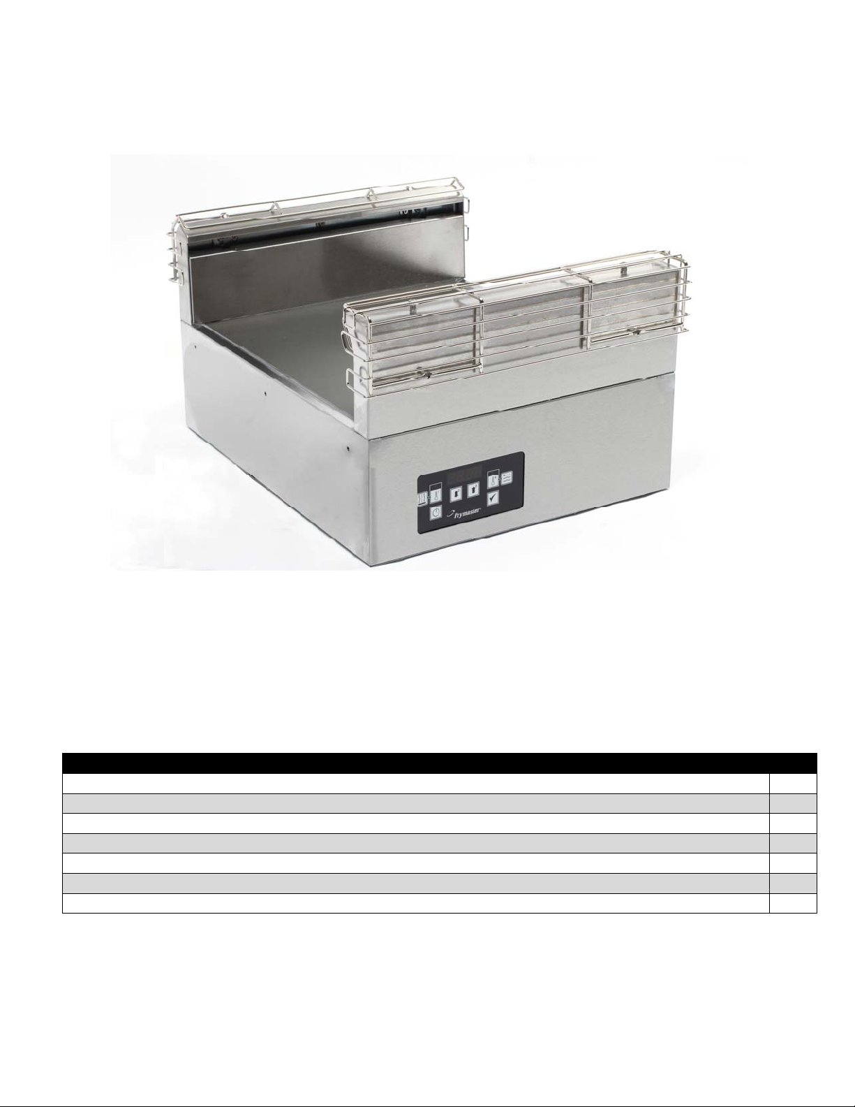
The Heated Landing Area or HLA is designed to hold assembled sandwiches. By circulating heated
air evenly across the open staging area, the Heated Landing Area keeps sandwiches hot without drying
or cooking. The Heated Landing Area meets all McDonald’s standards for safety, efficiency, food
safety, and cleanliness.
The filter screen is design to prevent debris from entering the
computer Cowl Assembly and clogging the blower assembly.
Simply fit the part on to the vent opening of the computer cowl
assembly. The filter screen will snap into position.
• Voltage – Two models are available: 208 VAC and 240 VAC*
Install Air Intake Filter
Power Requirements
• Frequency - 60 Hz
• Single Phase
• 20 amp Service
3.2 HLA Operation
1. Turn on unit at controller, which is behind a OAT panel.
2. When closing the store, remove all product from the HLA and
perform daily preventive maintenance in accordance with the MRC.
Turn off the HLA at the controller.
CAUTION – RISK OF FIRE/SHOCK
Do not restrict ventilation openings on
bottom of unit during installation.
The screen slips into slots on the air
intake side
.
DANGER
If the 240 VAC model is
operated on 208 VAC, the
unit will heat slowly and
may not reach maximum
temperature. If the 208
VAC model is operated on
240 VAC, component
damage is likely. To
ensure proper operation,
the power source should
match the voltage on the
rating plate on the bottom
of the HLA.
ALL UNITS (CORD CONNECTED OR PERMANENTLY CONNECTED) SHOULD BE
CONNECTED TO A GROUNDED POWER SUPPLY SYSTEM.
THIS APPLIANCE IS EQUIPPED WITH A GROUNDING PLUG FOR YOUR PR OTECTION
AGAINST SHOCK HAZARD AND MUST BE PLUGGED INTO A PROPERLY GROUNDED
RECEPTACLE. DO NOT CUT OR REMOVE THE GROUNDING PRONG FROM THIS PLUG.
3-2
Page 8

Heat Shield
Heat Shield
HLA
4: Annotated Overview
Air Intake
Shown without
removable screen
Heater Plate
Heated Air Outlet
Controller
4-1
Page 9

HLA
5: Controller Operation
Heater Plate
Temperature Switch
Air Heater
Temperature Switch
ON/OFF
5.1 Programming Temperatures
The setpoint temperature of the air heater and the heater plate are programmable via the computer. The heater
plate factory default is set to the McDonald’s standard of 160°F. The air heater factory default is set to the
McDonald’s standard of 220°F. If the factory default temperature settings are acceptable, skip to Section 7.2,
Page 2.
Ensure that the HLA computer is in the OFF position (nothing in the display).
Press
, then enter 1, 2, 3, 3. Use the numerals in the upper right-hand corner of each key.
Down
Switch
HLA Computer.
Up
Switch
Programming
Switch
Press
The display will read SET and the LEDs on both the Heater Plate button (1) and the Air Heater button (4) will
light (see previous diagram, HLA Computer). Press the button that corresponds to the heater you wish to
program.
Press the Up and Down Arrow Keys to achieve the desired set-point temperature, then press the Ch eck button
once. Both heater LEDs will again light.
Press
When both heaters are programmed, press
programming mode OR press either of the
Program as previously described.
, then , , , .
or to get desired setpoint, then press to lock the temperature in.
again to store the programmed setpoints and exit the
buttons (1 or 4) to change the setpoint temperature for a heater.
5-1
Page 10

HLA
5: Controller Operation
5.2 Operation
1. Press the power button, turning the HLA on (the display will light and cycle through an initialization
sequence). The display will read -LO- until the air heater and heater plate are within 15°F of setpoint. It will
take approximately 10 minutes for the HLA to achieve operating temperature.
NOTE: A small LED will light in the display when the heater plate or air heater is energized.
Press
The display will read LO until both heaters are within 15° F of setpoint.
When the HLA is ready for operation, the display reads R E d y (ready). Place product in the HLA in
accordance with the restaurant’s established procedures.
NOTE: To check the actual temperature of a heater, press the corresponding Temperature button once.
To check the setpoint temperature of a heater, press the button twice (an indicator will light when the
setpoint is displayed).
Heater Plate
Temperature Display
R E y
220
to turn on the computer.
Air Heater Activation
¡
d
220F
5-2
Page 11

HLA
5: Controller Operation
5.3 Switching Between Fahrenheit and Celsius Temperature Scales
Follow these steps to switch between Fahrenheit and Celsius temperatu re displays (refer to diagram, HLA
Computer, on Page 5-1):
1. Unplug unit from power supply.
2. Press and hold either temperature bulb button.
3. Plug unit back into power supply with button depressed.
4. S T O R will be shown in the display.
5. Release the temperature button.
6. Press the power button.
Now, the unit will display the temperature in Celsius rather than Fahrenheit.
5-3
Page 12

Symptom Possible Cause
No flow from air tower
HLA
6: Troubleshooting
• No power
• Circuit breaker out
• Low voltage
• Bad transformer
• Hi-limit out
No flow from air tower
• Bad latching relay
6-1
Page 13

HLA
7: Cleaning
1. Turn off HLA and allow to cool.
Allow 30 minutes for the HLA to cool.
Do not clean a hot HLZ.
2. Clean heated surfaces.
Clean all heated surfaces with a clean, sanitized towel soaked in McD APSC solution. Use a nylon pot
brush for stubborn stains or soil.
Sanitizer solution,
McD APSC
Do not use McD Sanitizer, no-scratch pads, scrapers, or other brushes. They can damage the surface.
3. Clean other surfaces.
Clean the stainless steel surfaces with a fresh clean, sanitized towel soaked in McD APSC solution.
ON/OFF
7-1
Page 14

A
Shipping Address: 8700 Line Avenue, Shreveport, Louisiana 71106
TEL 1-318-865-1711 FAX (Parts) 1-318-219-7140 FAX (Tech Support) 1-31 8-219-7135
Price: $6.00
819-6791
FEB 12
PRINTED IN THE UNITED STATES
SERVICE HOTLINE
1-800-551-8633
 Loading...