


FHWC3625MWB
Frigidaire FHWC3625MWB, FHWC3625MWA, FHWC3625MSB, FHWC3625MSA, FHWC3625MBA Owner’s Manual
...
mr
USA 1-800-944-9044
www.frigidaire.com
Canada 1-800-265-8352
www.frigidaire.ca
LI3OKC / 316902495
May/13
CONTENTS
Important Safety Instructions ............................... 3
List of materials ................................................... 5
Electrical requirements ......................................... 5
Location requirements .......................................... 6
Product dimensions .............................................. 6
Venting Requirements .......................................... 7
Prepare the location ............................................. 8
Install Range Hood (Ducted version) ..................... 10
Make Electrical Connection .................................... 12
Installing Range Hood (Recirculating version) ......... 10
Range Hood Use .................................................. 13
Range Hood Care ................................................. 14
Troubleshooting ................................................... 15
Warranty Information ........................................... 16
Thank you for choosing Frigidaire.
This Use & Care Guide is part of our commitment to
customer satisfaction and product quality throughout the
service life of your new appliance.We view your purchase
as the beginning of a relationship. To ensure our ability to
continue serving you, please use this page to record
important product information.
Need help??
Visit the Frigidaire web site at www.frigidaire.com
Before you call for service, there are a few things you can
do to help us serve your better.
Read this Use & Care manual.
It contains instructions to help you use and maintain your
range properly.
If you received a damaged range Hood...
immediately contact the dealer (or builder) that sold you
the range hood.
Save time and money.
Check the "Troubleshooting" list. This section helps step
you through some common problems that might occur. If
you do need service, help is only a phone call away. Call
Frigidaire Customer Services at 1-800-944-9044.
Product Registration
Registering your product with Frigidaire enhances our
ability to serve you. You can register online at
www,frigidaire,com or by dropping your Product
Registration Card in the mail.
Location
Serial Plate
Serial plate location:
Find it on the left side of the range hood.
Record model & serial numbers here
Purchase date
Model number
Serial number
2
Read all instructions before using this appliance.
Save these instructions for future references
Approved for residential appliances
For residential use only
Do not attempt to install or operate your appliance until
you have read the safety precautions in this manual.
Safety items throughout this manual are labeled with a
WARNING or CAUTION based on the risk type.
_This is the safety alert symbol. It is used to alert you to
potential personal injury hazards. Obey all safety mes-
sages that follow this symbol to avoid possible injury or
death.
This symbol alerts you to situations that may
cause serious body harm, death or property
damage.
CAUTION indicates a potentially hazardous
situation which, if not avoided, may result in
minor or moderate injury.
IMPORTANT indicates installation, operation,
maintenance or valuable information that is not hazard
related.
TO REDUCE THE RISK OF FIRE, ELECTRIC
SHOCK, OR INJURY TO PERSONS, OBSERVE THE
FOLLOWING:
A. Use this unit only in the manner intended by the
manufacturer. If you have questions, contact the
manufacturer
B. Before servicing or cleaning the unit, switch power
off at service panel and lock service panel
disconnecting means to prevent power from
being switched on accidentally. When the service
disconnecting means cannot be locked, securely
fasten a prominent warning device, such as a tag, to
the service panel.
C.Installation Work and Electrical Wiring Must Be Done
By Qualified Person(s) In Accordance With all
Aplicable Codes & Standards, Including Fire-rated
Construction.
D.Sufficient air is needed for proper combustion and ex
hausting of gases through the flue (Chimney) of fuel
burning equipment to prevent back- drafting. Follow
the heating equipment manufacturers guideline and
safety standards such as those published by the
National Fire Protection Association (NFPA), the
American Society for Heating, Refrigeration and Air
Conditioning Engineers (ASHRAE), and the local code
authorities.
E.When cutting or drilling into wall or ceiling, do not
damage electrical wiring and other hidden utilities.
F. Ducted systems must always be vented to the
outdoors.
IMPORTANT SAFETY INSTRUCTIONS
FOR GENERAL VENTILATING USE ONLY. DO NOT
USE TO EXHAUST HAZARDOUS OR EXPLOSIVE
MATERIALS OR VAPORS.
To reduce risk of fire and to properly exhaust
air, be sure to duct air outside - do not vent ex-
haust air into spaces within walls, ceilings,
attics, crawl spaces, or garages.
TO REDUCE THE RISK OF FIRE, USE ONLY METAL
DUCT WORK.
Install this hood in accordance with all requirements
specified.

To Reduce The Risk Of Fire Or Electric Shock, Do
Not Use This Hood With Any External Solid State
Speed Control Device.
TO REDUCE THE _SK OF A RANGE TOP GREASE
FIRE.
a)Never leave surface units unattended at high
settings. Boilovers cause smoking and greasy
spillovers that may ignite. Heat oils slowly on low or
medium settings.
b)AIways turn hood ON when cooking at high heat or
when flambeing food (I.e. Crepes Suzette, Cherries
Jubilee, Peppercorn Beef Flambe').
c) Clean ventilating fans frequently. Grease should not
be allowed to accumulate on fan or filter.
d)Use proper pan size. Always use cookware
appropriate for the size of the surface element.
TO REDUCE THE RISK OF INJURY TO PERSONS,
IN THE EVENT OF A RANGE TOP GREASE FIRE,
OBSERVE THE FOLLOWING:
a)SMOTHER FLAMES with a close - fitting lid, cookie
sheet, or other metal tray, then turn off the gas
burner or the electric element.
BE CAREFUL TO PREVENT BURNS. If the flames do
not go out immediately, EVACUATE AND CALL THE
FIRE DEPARTMENT.
b)NEVER PICK UP A FLAMING PAN - you may be
burned.
c)DO NOT USE WATER, including wet dishcloths or
towels - a violent steam explosion will result.
d)Use an extinguisher ONLY if:
1)You know you have a class ABC extinguisher,
and you already know how to operate it.
2)The fire is small and contained in the area
where it started.
3)The fire department is being called.
4)You can fight the fire with your back to an exit.
OPERATION
Always leave safety grills and filters in place.Without
these components, operating blowers could catch onto
hair, fingers and loose clothing.
The manufacturer declines all responsibility in the
event of failure to observe the instructions given here
for installation,maintenance and suitable use of the
product. The manufacturer further declines all respon-
sibility for injury due to negligence and the warranty of
the unit automatically expires due to improper mainte-
nance.

LIST OF MATERIALS
ELECTRICAL REQUIREM ENTS
Parts included in your hood
• 4 - 0.45 x 1.3 cm mounting screws
• 31/4" x 10" (8.3 x 25.4 cm) rectangular metal vent
system.
NOTE: An optional 7" round duct kit is available. You can
order this kit as part number 5304487139.
Parts Needed
• 2 - UL listed wire connectors
• 1- 75W max, 120Vincandescent light bulb
• Wall or roof cap with damper to match vent system
• Vent clamps/duct tape as required
• UL listed or CSA approved 1/2"strain relief
Tools/Materials required
• Drill
• 11/4" (3.0 cm) drill bit
• 1/8"(0.3 cm) drill bit for pilot holes
• Pencil
• Wire stripper or utility knife
• Tape measure or ruler
• Caulking gun and weatherproof
caulking compound
• Flat-blade screwdriver
• Phillipsscrewdriver
• Saberor keyhole saw
For cabinets with recessed bottoms:
• Two 2" (5.1 cm) wide fillerstrips. Length and
thickness determined by recess dimensions.
• Four flat head wood screwsor machine screws
with washers and nuts (to attach fillerstrips).
Observe all governing codes and ordinances.
Ensure that the electrical installation is adequate and in
conformance with National Electrical Code, ANSI/NFPA
70 (latest edition), or CSA Standards C22.1-94, Canadian
Electrical Code, Part 1 and C22.2 No. 0-M91 (latest edi-
tion) and all local codes and ordinances.
If codes permit and a separate ground wire is used, it is
recommended that a qualified electrician determine that
the ground path is adequate.
A copy of the above code standards can be obtained
from:
National Fire Protection Association
One Batterymarch Park
Quincy, MA 02269
CSA International
8501 East Pleasant Valley Road
Cleveland, OH 44131-5575
• A 120 volt, 60 Hz., AC only, 15-amp, fused
electrical circuit is required.
• If the house has aluminum wiring, follow the
procedure below:
1. Connect a section of solid copper wire to the
pigtail leads.
2. Connect the aluminum wiring to the added
section of copper wire using special co
nectors and/or tools designed and UL listed
for joining copper to aluminum.
Follow the electrical connector manufacturer's recom-
mended procedure. Aluminum/copper connection must
conform with local codes and industry accepted wiring
practices.
• Wire sizes and connections must conform with
the rating of the appliance as specified on the
model/serial rating plate.
The model/serial plate is located on the left side of
the range hood.
• Wire sizes must conform to the requirements of
the National Electrical Code, ANSI/NFPA 70 (la
est edition), or CSA Standards C22. 1-94, Canad
an Electrical Code, Part 1 and C22.2 No. 0-M91
(latest edition) and all local codes and ordinances.
Observe all governing codes and ordinances.
• It is the installer's responsibility to comply with
installation clearances specified on the model/serial
rating plate. The model/serial rating plate is located
inside the range hood on the left side (See page 2
for location). Range hood location should be away
from strong draft areas, such as windows, doors and
strong heating vents.
• Cabinet opening dimensions that are shown must
be used. Given dimensions provide minimum
clearance. Consult the cooktop/range manufacturer
installation instructions before making any cutouts.
• Grounded electrical outlet is required. See
"Electrical Requirements" section.
• All openings in ceiling and wall where canopy hood
will be installed must be sealed.
For Mobile Home Installations
The installation of this range hood must conform to the
Manufactured Home Construction Safety Standards, Title
24 CFR, Part 328 (formerly the Federal Standard for
Mobile Home Construction and Safety, Title 24, HUD, Part
280) or when such standard is not applicable, the stan-
dard for Manufactured Home Installation 1982 (Manu-
factured Home Sites, Communities and Setups) ANSI
A225.1/NFPA 501A, or latest edition, or with local codes.
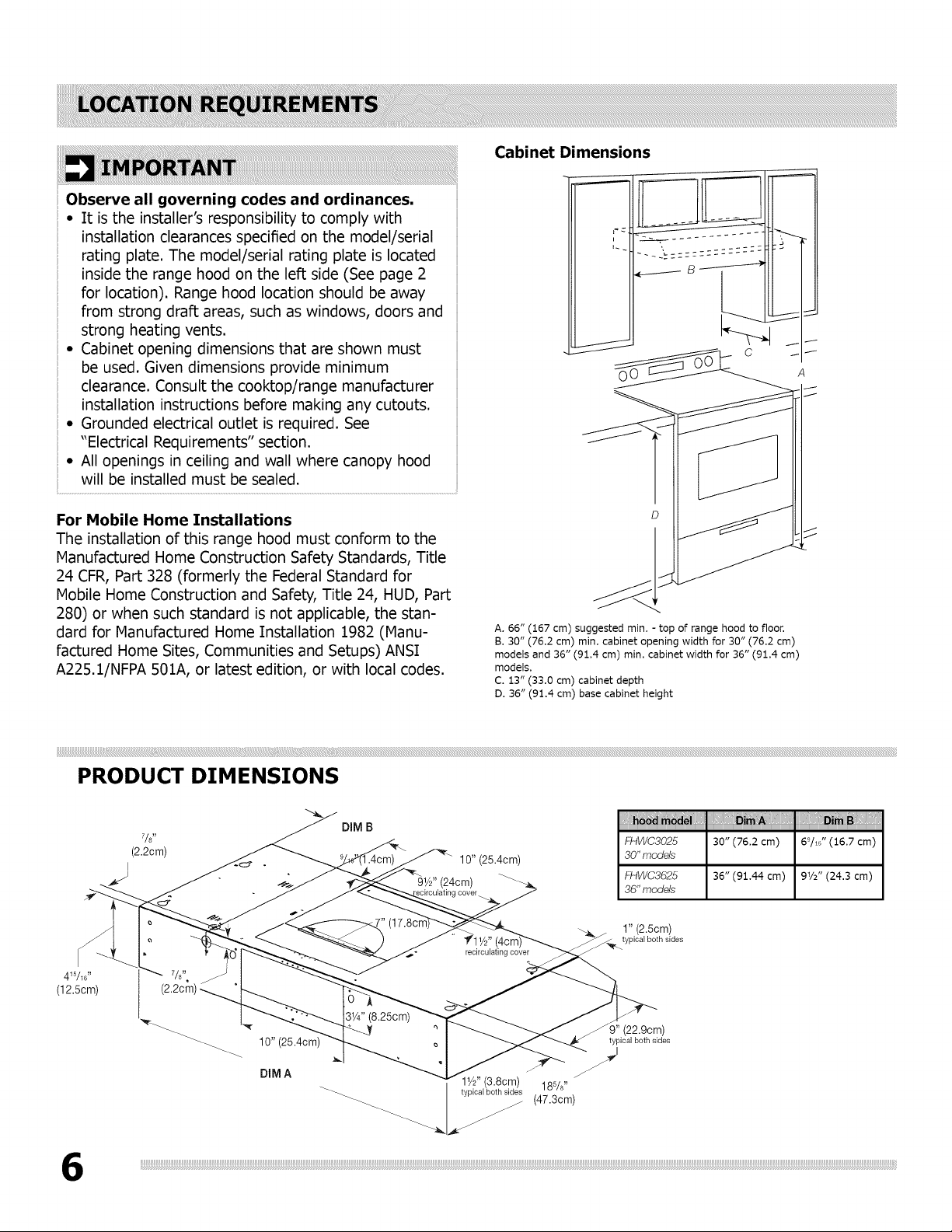
Cabinet Dimensions
C
A. 66" (167 cm) suggested min. - top of range hood to floor.
B. 30" (76.2 cm) rain. cabinet opening width for 30" (76.2 cm)
models and 36" (91,4 cm) min. cabinet width for 36" (91,4 cm)
models.
C. 13" (33.0 cm) cabinet depth
D. 36" (91.4 cm) base cabinet height
PRODUCT DIMENSIONS
(2.2cm)
J
10" (25.4cm) typicalbothsides
DIM A _']
DIM B
10" (25.4cm)
lye" (3.8cm) 18%"
typical both sides (47.3cm)
od ,' ,'
F_4WC3025 30" (76,2 cm) 6_/t_" (16,7 cm)
30" models
F_4WC3625 36" (91,44 cm) 9_/_" (24.3 cm)
36" models
-_ 1" (2.5cm)
typical both sides
)" (22.9cm)
 Loading...