


Frigidaire FFPA1422T1, FFPH1222T1, FFPA1222T1, FFPH1422T1, FFPA0822T1 Owners Manual
|
|
|
|
|
|
|
|
|
|
|
|
|
|
|
|
|
|
|
|
|
|
|
|
|
|
|
|
|
|
|
|
|
|
|
|
|
|
|
|
|
|
|
|
|
|
|
|
|
|
|
|
|
|
..............................ImportantSafetyInstructions |
2-3 |
|
.....................................AirConditionerFeatures |
8 |
||||||||||||||||||||||
ProductRegistration............................................... |
4 |
OperatingInstruction...................................... |
8-16 |
|||||||||||||||||||||||
NormalSounds....................................................... |
4 |
CareandCleaning............................................. |
17 |
|||||||||||||||||||||||
UnitDescription...................................................... |
5 |
BeforeYouCall.................................................. |
18 |
|||||||||||||||||||||||
AccessoriesIncluded............................................. |
5 |
|
MajorApplianceLimitedWarranty.................... |
19 |
||||||||||||||||||||||
InstallationInstructions....................................... |
6-7 |
|
|
|
|
|
|
|
|
|
|
|
|
|
|
|||||||||||

Important Safety Instructions |
|
NOTE: |
|
NOTE: |
WARNING |
|
WARNING |
WARNING |
|
|
WARNING |
SAFETY PRECAUTIONS |
|
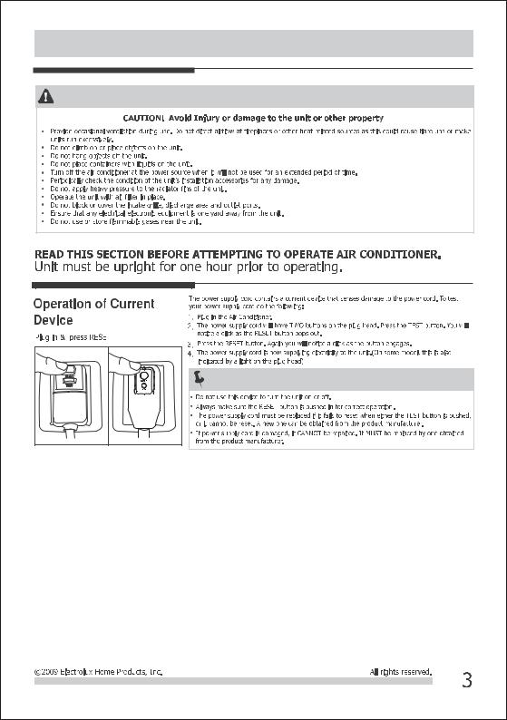
Important Safety Instructions |
SAFETY PRECAUTIONS |
NOTE: |
Product Registration & Normal Sounds
Product Registration Record Your Model and Serial Numbers
Record in the space provided below the mode and serial numbers. Onallmodels,the serialplateislocatedonthesideofthecabinet.
Model No.
Serial No.
Register Your Product
The self-addressed PRODUCTREGISTRATIONCARDshouldbefilledincompletely, signedandreturnedtotheFrigidaireCompany.
Normal Sounds
Sound of RushingAir
Atthetopoftheunit,youmay hearthesoundofrushingair beingmovedbythefan.
High pitched Chatter
Today’shighefficiency compressorsmayhavea highpitchedchatterduring thecoolingcycle.
Gurgle/Hiss
“Gurglingorhissing”noisemaybe heardduetorefrigerantpassing throughevaporatorduringnormal operation.
Vibration
Unitmayvibrateandmakenoise becauseofunevenfloor.
|
Unit Description &Accessories Included |
|||||
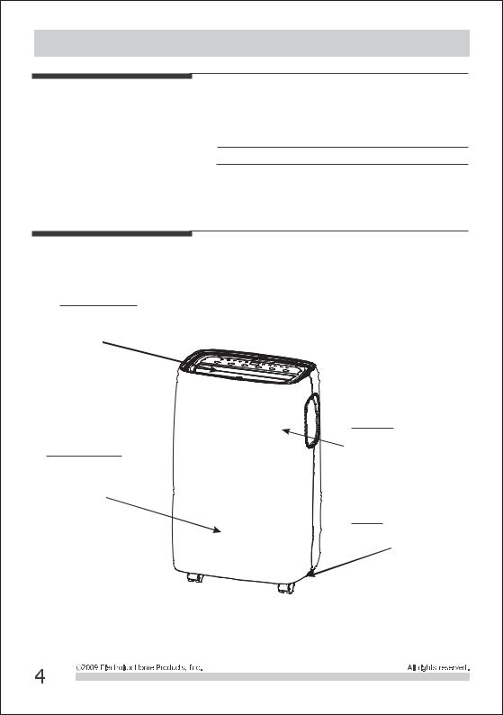
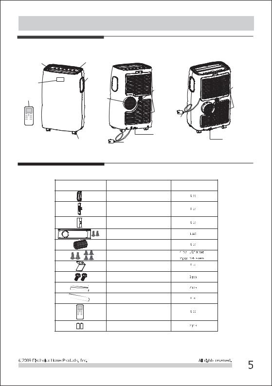
Unit Description |
|
|
|
|
|
|
AirOutletGrill |
ControlPanel |
|
|
|
|
|
Signal |
Carrying |
|
|
|
|
|
Handle |
|
|
|
|
Continuous |
|
Receiver |
|
|
Continuous |
|
|
|
|
|
|
|
|
DrainOutlet |
|
Remote |
|
|
DrainOutlet |
|
|
|
Air |
|
|
|
|
|
|
Control |
|
|
|
|
|
|
Exhaust |
|
|
|
|
|
|
|
|
|
|
|
|
|
|
|
|
AirIntake |
|
|
AirIntake |
|
|
|
|
|
|
|
|
|
|
Power |
|
|
|
|
|
|
Cord |
|
|
|
|
|
|
Bottom |
|
|
|
|
Castor |
|
DrainOutlet |
|
|
Bottom |
|
Powercord |
|
|
DrainOutlet |
||
|
|
(FFPA1222T1 |
FFPH1222T1 |
(FFPA0822T1 |
FFPA1022T1) |
|
|
|
FFPA1422T1 |
FFPH1422T1) |
|
|
|
Accessories Included |
|
|
|
|
|
|
|
PARTS: |
PARTS NAME: |
QUANTITY: |
|
||
|
|
WindowKitConnectorA |
|
|
|
|
|
|
ExhausthoseconnectorB |
|
|
|
|
|
|
(FFPA1222T1 |
FFPH1222T1 |
|
|
|
|
|
FFPA1422T1 |
FFPH1422T1) |
|
|
|
|
|
ExhausthoseconnectorB |
|
|
|
|
|
|
(FFPA0822T1 |
FFPA1022T1) |
|
|
|
|
|
WindowKit |
|
|
|
|
|
|
Exhaust Hose |
|
|
|
|
|
|
|
|
( |
) |
|
|
|
Screws |
( + |
) |
|
|
|
|
SafetyLock |
|
|
|
|
|
|
Bolts |
|
|
|
|
|
|
FoamsealA |
|
|
|
|
|
|
FoamsealB |
|
|
|
|
|
|
Remote Control |
|
|
|
|
|
|
Battery |
|
|
|
|
Installation Instructions
Installation Instructions
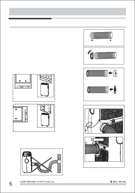
EXHAUSTING HOTAIR
In the Cool Mode the appliance must be placed close to a window or opening so that the warm exhaust air can be ducted outside.
First position unit on a flat floor and make sure there’s a minimum of 12″clearance around the unit, and is within the vicinity of a single circuit outlet power source.
1.Extend either side of the hose(Fig.1) and screw the hose to connectorA(Fig.2).
2.Extend the other side of the hose and screw it to connector B (Fig. 3).
3.Install the connector B into the unit (Fig.4).
4.Affix the connectorAinto the window slider kit and seal. (Fig.5&6)
Vertical |
window |
WindowSliderKit |
Minimum:26.6″(67.5cm) |
Maxmum:485. ″(123cm) |
Fig.5 |
Horizontal |
window |
WindowSliderKit
Minimum:26.6″(67.5cm)
Maxmum:485. ″(123cm) Fig.6
The hose can be extended from its original length of 15″up to 59″,but it is the best to keep the length to minimum required. Also make sure that the hose does not have any sharp bends or sags.(Fig.7)
Fig.7 |
Extendthesideofhose Fig.1
|
Fig.2 |
FFPA0822T1 |
FFPA1022T1 |
|
Fig.3 |
FFPA1222T1 |
FFPH1222T1 |
FFPA1422T1 |
FFPH1422T1 |
Fig.4 |
|
Slideonto |
|
FFPA0822T1 |
FFPA1022T1 |
1 Slideonto |
|
2 Lock |
|
FFPA1222T1 |
FFPH1222T1 |
FFPA1422T1 |
FFPH1422T1 |
 Loading...