

Page 1

Istruzioni per l’uso e l’installazione
Cappa
Instructions for use and installation
Cooker Hood
Mode d’emploi et installation
Hotte de Cuisine
Bedienungsanleitung und Einrichtung
Dunstabzugshaube
Kullan
ım ve montaj talimatları
Davlumbaz
Instrukcja obsługi i instalacji
Okap kuchenny
FTC 622
FTC 922
IT
GB
FR
DE
TR
PL
Page 2

IT
2
2
Libretto di Istruzioni
INDICE
CONSIGLI E SUGGERIMENTI ..............................................................................................................................................8
CARATTERISTICHE..............................................................................................................................................................9
INSTALLAZIONE..................................................................................................................................................................10
USO......................................................................................................................................................................................12
MANUTENZIONE.................................................................................................................................................................13
Page 3

EN
3
3
Instructions Manual
INDEX
RECOMMENDATIONS AND SUGGESTIONS....................................................................................................................14
CHARACTERISTICS............................................................................................................................................................15
INSTALLATION ....................................................................................................................................................................16
USE.......................................................................................................................................................................................18
MAINTENANCE....................................................................................................................................................................19
Page 4

FR
4
4
Manuel d’Instructions
SOMMAIRE
CONSEILS ET SUGGESTIONS ..........................................................................................................................................20
CARACTERISTIQUES.........................................................................................................................................................21
INSTALLATION ....................................................................................................................................................................22
UTILISATION........................................................................................................................................................................24
ENTRETIEN..........................................................................................................................................................................25
Page 5

DE
5
5
Bedienungsanleitung
INHALTSVERZEICHNIS
EMPFEHLUNGEN UND HINWEISE....................................................................................................................................26
CHARAKTERISTIKEN..........................................................................................................................................................27
MONTAGE............................................................................................................................................................................28
BEDIENUNG.........................................................................................................................................................................30
WARTUNG............................................................................................................................................................................31
Page 6

TR
6
6
Kullanim Kilavuku
IÇERIKLER
TAVSIYELER VE ÖNERILER ..............................................................................................................................................32
ÖZELLIKLER........................................................................................................................................................................33
MONTAJ...............................................................................................................................................................................34
KULLANIM............................................................................................................................................................................36
BAKIM...................................................................................................................................................................................37
Page 7

PL
7
7
Instrukcja Obslugi
SPIS TREŚCI
UWAGI I SUGESTIE.............................................................................................................................................................38
WŁAŚCIWOŚCI TECHNICZNE............................................................................................................................................39
INSTALACJA........................................................................................................................................................................40
UŻYTKOWANIE....................................................................................................................................................................42
KONSERWACJA..................................................................................................................................................................43
Page 8
IT
8
8
CONSIGLI E SUGGERIMENTI
Questo libretto di istruzioni per l'uso è previsto per più versioni dell'apparecchio.
Possibile che siano descritti singoli particolari della dotazione, che non riguardano il
Vostro apparecchio.
INSTALLAZIONE
• Il produtto re declina qualsiasi re sponsabilità per dann i dovuti ad installa zione non
corretta o non conforme alle regole dell’arte.
• La distanza minima di sicurezza tra il Piano di cottura e la Cappa deve essere di
650 mm.
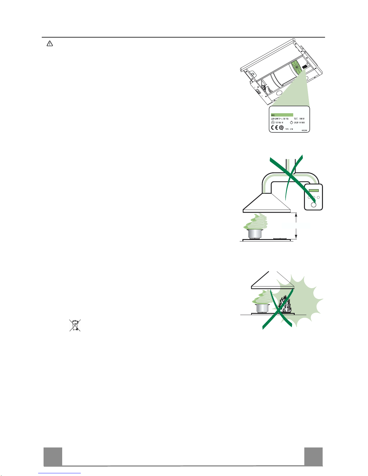
• Verificare che la tensione di rete corrisponda a quella riportata nella targhetta posta
all’interno della Cappa.
• Per Apparecchi in Classe Ia accertarsi che l’impianto elettrico domestico ga rantis ca
un corretto sc ar ico a terra.
• Collegare la Cappa all’uscita dell’aria aspirata con tubazione di diametro pari o
superiore a 12 0 mm. Il percorso della tubazione deve essere i l più breve possibile.
• Non collegare la Cappa a condotti di scarico dei fumi prodotti da combustione (caldaie, caminetti, ecc.).
• Nel caso in cui nella stanza vengano utilizzati sia la Cappa che apparecchi non
azionati da energia elettrica (ad esempio apparecchi utilizzatori di gas), si deve
provvedere ad una aerazione sufficiente dell’ambiente. Se la cucina ne fosse
sprovvista, praticare un’apertura che comunichi con l’esterno, per garantire il richiamo d’aria pulita.
USO
• La Cappa è stata progettata esclusivamente per uso domestico, per abbattere gli
odori della cucina.
• Non fare mai uso impr oprio della Cappa.
• Non lasciare fiamme libere a forte intensità s otto la Cappa in funzione.
• Regolare sempre le fiamme in modo da evitare una evidente fuoriuscita laterale
delle stesse ri spetto al fondo delle pentole.
• Controllare le friggitrici durante l’uso: l’olio surriscaldato potrebbe infiammarsi.
• Non preparare ali menti flambè sott o la cappa da cucina; pericolo d'incendio.
• La Cappa non deve essere utilizzata da bambini o persone non abilitate all’uso
corretto.
MANUTENZIONE
• Prima di procedere a qualsiasi operazione di manutenzione, disinserire la Cappa
togliendo la spina elettrica o spegnendo l’interruttore generale.
• Effettuar e u na sc rup o los a e tempestiva m anu te nz io ne dei Filtri s econdo gli in tervalli
consigliati.
• Per la pulizia delle superfici de lla Cappa è sufficien te utilizzare un panno u mido e
detersivo li quido neutro.
Il simbolo
sul prodotto o sulla confezione indica che il prodotto non deve essere
considerato come un normale rifiuto domestico, ma deve essere portato nel punto di
raccolta appropriato per il riciclaggio di apparecchiature elettriche ed elettroniche.
Provvedendo a smaltire questo prodotto in modo appropriato, si contribuisce a evitare
potenziali conseguenze negative per l’ambiente e per la salute, che potrebbero derivare da uno smaltimento inadeguato del prodotto. Per informazioni più dettagliate sul
riciclaggio di questo prodotto, contattare l’ufficio comunale, il servizio locale di smaltimento rifi ut i o il negozio in cui è st ato acquistato il prodotto.
650 mm min.
Page 9
IT
9
9
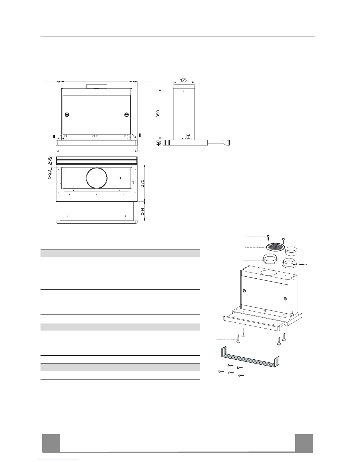
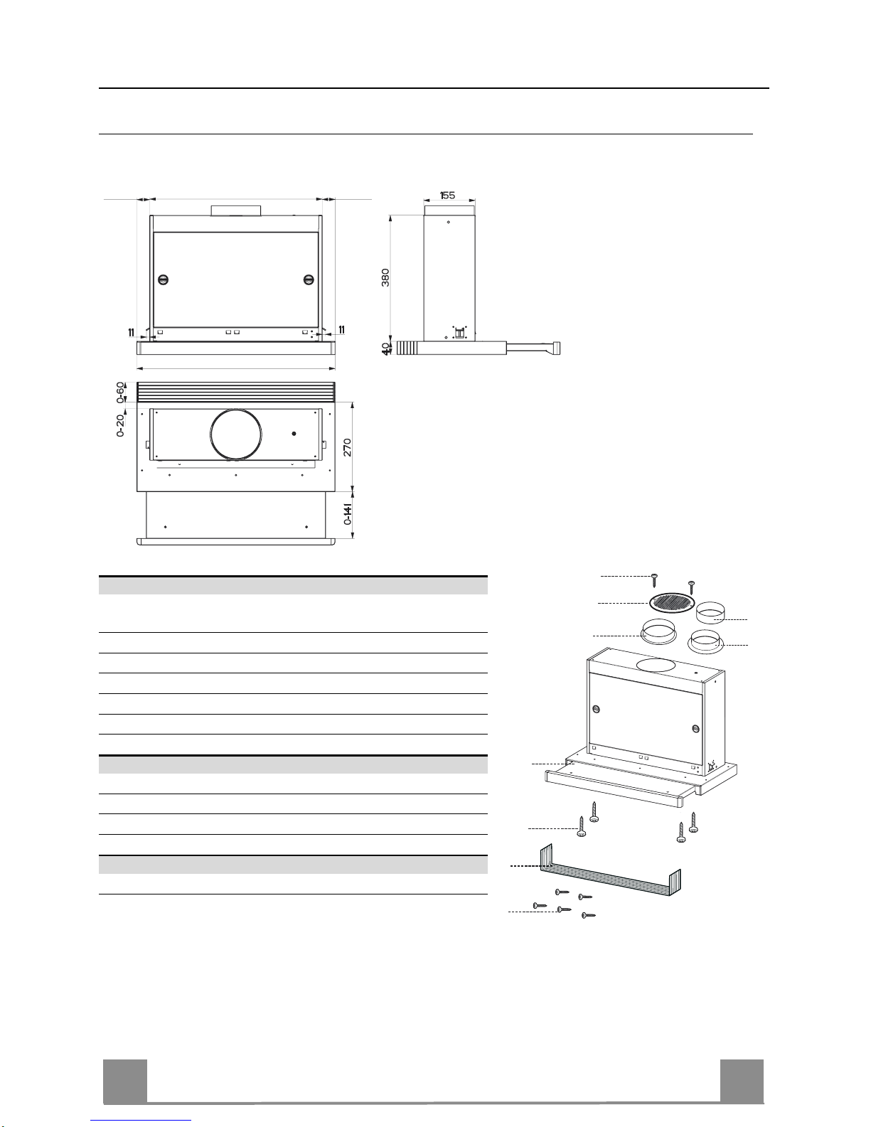
CARATTERISTICHE
Ingombro
490 - 520
548 - 598 - 898
29-39 29-39
Componenti
Rif. Q.tà Componenti di Prodotto
1 1 Corpo Cappa completo di: Comandi, Luce, Gruppo
Ventilatore, Filtri
8 1 Griglia direzionata uscita aria
9 1 Flangia ø 150
10a 1 Flangia ø 120
10b 1 Anello di Maggiorazione ø 120-125 mm
20 1 Profilo chiusura
Rif. Q.tà Componenti di Installazione
12a 4 Viti 3,5 x 16
12e 2 Viti 2,9 x 12,7
12f 5 Viti 2,9 x 9, 5
Q.tà Documentazione
1 Libretto Istruzioni
12e
8
9
1
12a
20
12f
10a
10b
Page 10
IT 110
X
162
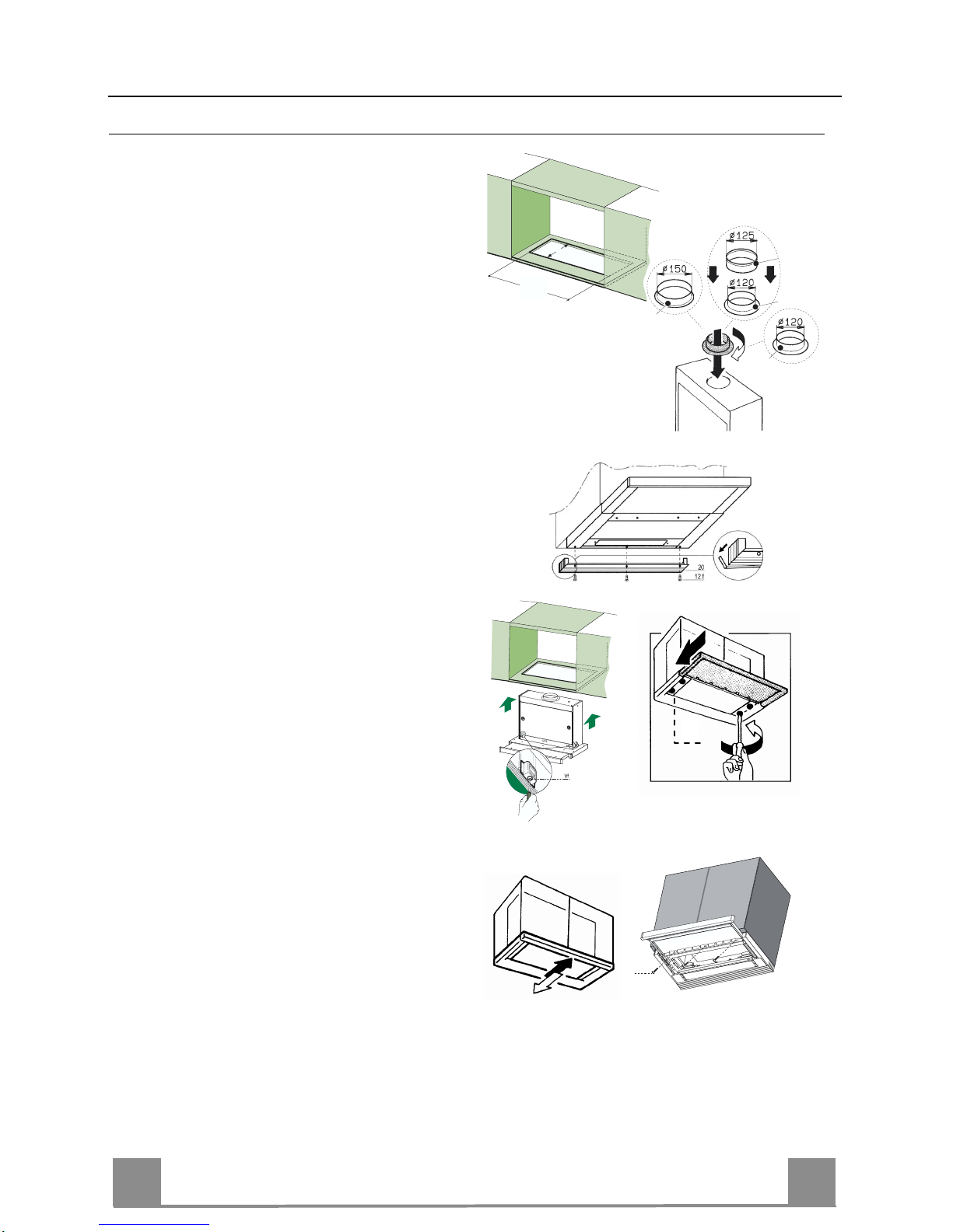
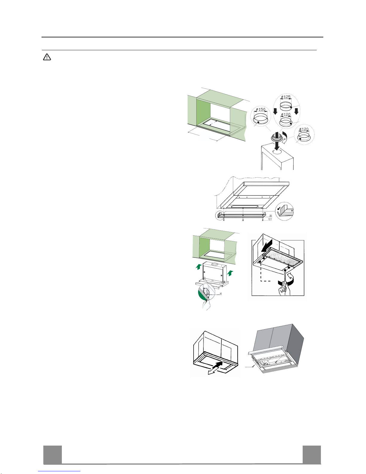
INSTALLAZIONE
Foratura Piano di supporto e Montaggio Cappa
• La Cappa può essere installata direttamente
sul piano inferiore dei Pensili (650 mm min.
dal Piano di Cottura) con i Supporti laterali a
scatto.
• Praticare un incasso sul piano inferiore del
Pensile, come indicato (fig.1); la quota X
deve essere di 523 mm per la cappe da 60 e
90 cm, di 493 mm per le cappe da 55 cm (disponibili per il mercato svizzero)
• Inserire la flangia nel foro superiore di scarico. (fig.2)
• Avvitare il profilo di chiusura 20 alla parte
posteriore della cappa utilizzando le viti 12f
(2,9 x 9,5) in dotazione. (fig.3)
• Aprire il carrello aspirante.
• Togliere i Filtri Antigrasso uno alla volta,
agendo sugli appositi agganci.
• Richiudere il carrello aspirante.
• Inserire la Cappa fino ad agganciare i Supporti laterali a scatto. (fig.4)
• Aprire il carrello aspirante.
• Bloccare definitivamente serrando le Viti Vf
dal sotto della Cappa. (fig.4)
• Se è necessario effettuare degli aggiustamenti dell'intero corpo portafiltri, operare
come segue:
• Allentare le quattro viti di regolazione Vr
e richiudere il carrello. (fig.5)
• Traslare l'intero corpo portafiltri fino ad
ottenere l'allineamento desiderato con il
pensile. (fig.6)
• Sempre mantenendo fermo il corpo cappa
estrarre il carrello e serrare le viti di regolazione Vr. (fig.5)
• Ora è possibile fissare definitivamente la
cappa al pensile usando le viti 12a (3,5 x
16) in dotazione. (fig.7)
• Rimontare i Filtri antigrasso.
• Richiudere il carrello aspirante.
1 3 4
Vr
5
6
12a
7
9
10a
10a
10b
2
Page 11
IT 111
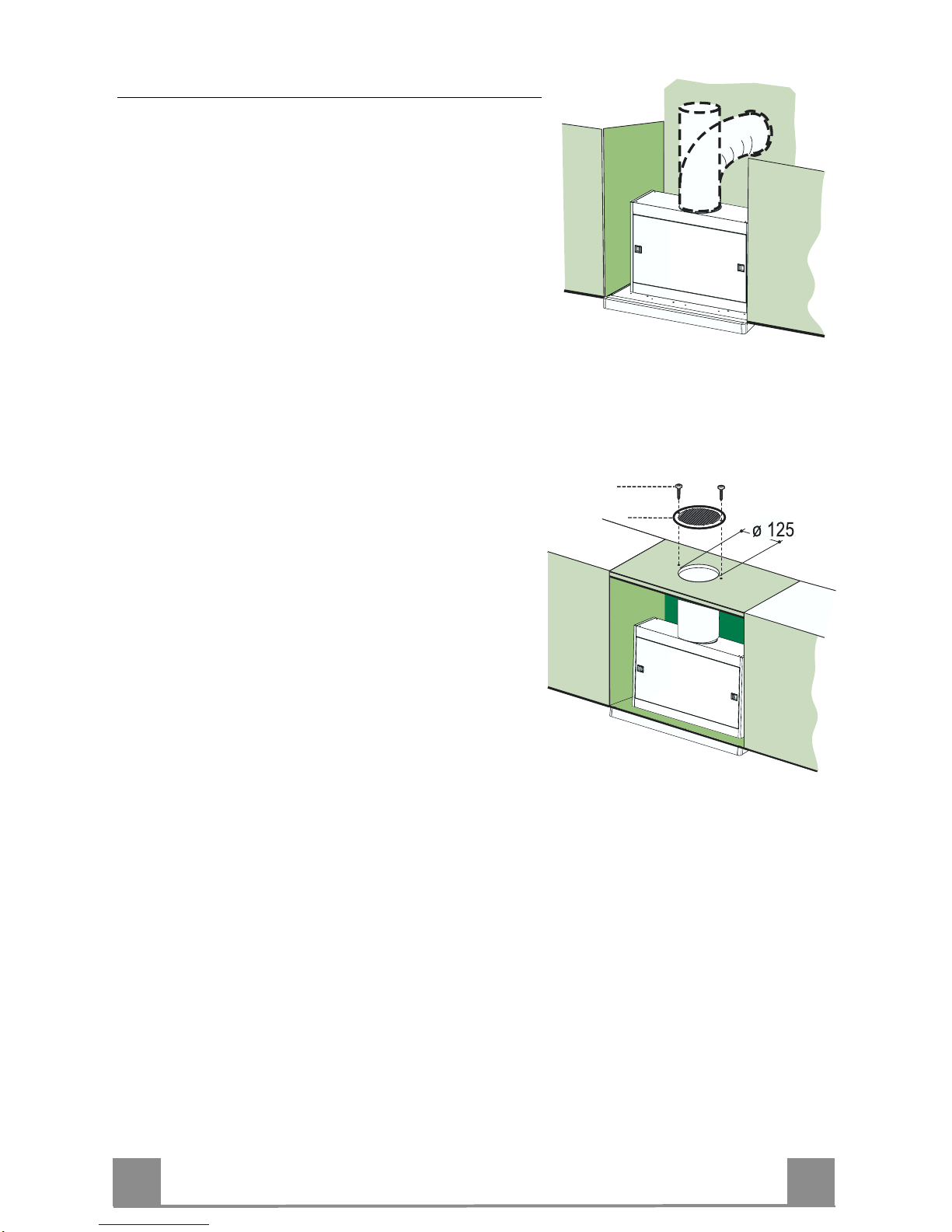
Connessioni
USCITA ARIA VERSIONE ASPIRANTE
Per installazione in Versione Aspirante collegare la
Cappa alla tubazione di uscita per mezzo di un tubo
rigido o flessibile dello stesso diametro della flangia
precedentemente in stallata
• Fissare il tubo con adeguate fascette stringitubo. Il
materiale occorrente non è in dotazion e.
• Togliere eventuali Filtri Antiodore al Carbone attivo.
USCITA ARIA VERSIONE FILTRANTE
• Praticare un foro ø 125 mm sull’eventuale Mensola
soprastante la Cappa.
• Inserire la Flangia 10a sull’uscita del Corpo Cappa.
• Collegare la Flangia al foro di uscita sulla Mensola
soprastante la Cappa con un tubo rigido o flessibile di
ø120 mm.
• Fissare il tubo con adeguate fascette stringitubo. Il
materiale occorrente non è in dotazion e.
• Fissare la Griglia direzionata 8 sull’uscita con 2 Viti
12e (2,9 x 12,7) in dotazione.
• Assicurarsi dell a presenza dei Filtri antiodore al Carbone attivo.
12e
8
CONNESSIONE ELETTRICA
• Collegare la Cappa all’Alimentazione di Rete interponendo un Interruttore bipolare con apertura dei contatti di almeno 3 mm.
Page 12
IT 112
USO
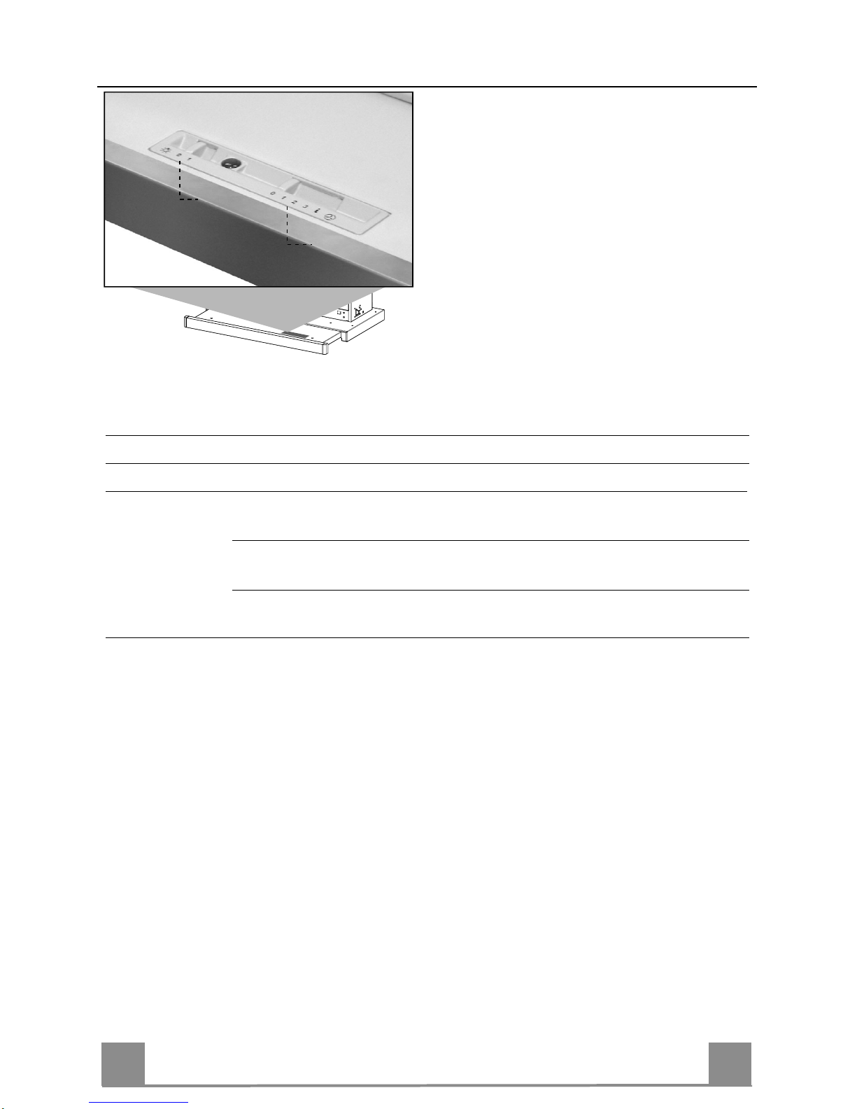
L
M
Le varie funzioni vengono attivate automatica mente con l’estrazione del carrello. Per spegnere
le funzioni impostate sarà sufficiente richiudere il carrello.
TASTO FUNZIONE
L Luci Accende e spegne l’Impianto di Illuminazione.
M Motore Accende e spegne il motore Aspirazione.
1. Velocità minima, adatta ad un ricambio d’aria continuo particolarmente
silenzioso,in presenza di pochi vapori di cottura.
2. Velocità media, adatta alla maggior parte delle condizioni d’uso, dato
l’ottimo rapporto tra portata d’aria trattata e livello sonoro.
3. Velocità massima, adatta a fronteggiare grandi emissioni di vapore di
cottura,anche per tempi prolungati.
Page 13
IT 113
MANUTENZIONE
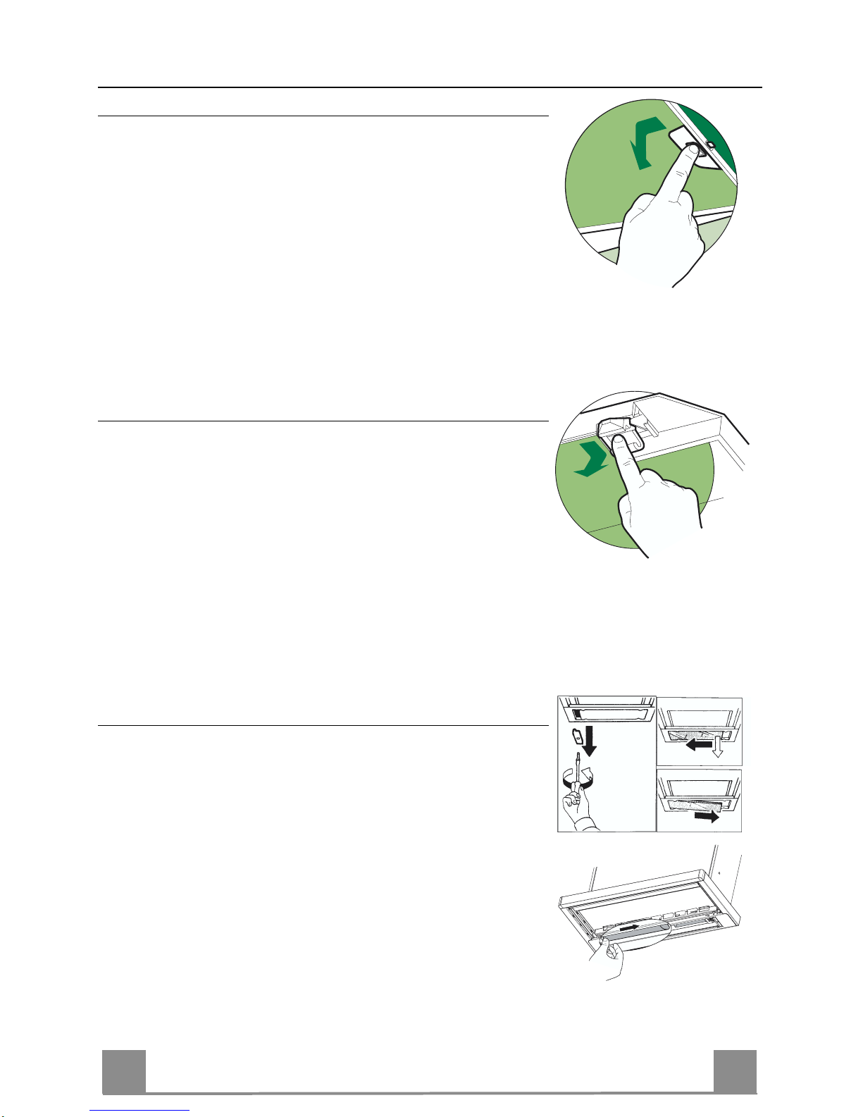
Filtri antigrasso
PULIZIA FILTRI AN TIGR A SSO ME TAL L ICI AUTO PO RTAN TI
• Sono lavabili anche in lavastoviglie, e necessitano di essere
lavati ogni 2 mesi circa di utilizzo o più frequentemente, per un
uso particolarmente intenso.
• Estrarre il carrello aspirante.
• Togliere i Filtri uno alla volta, agendo sugli appositi agganci.
• Lavare i Filtri evitando di piegarli, e lasciarli asciugare prima
di rimontarli. (Un ’eventuale cambiamento del colo re della superficie del filtro, che potrebbe verificarsi nel tempo, non pregiudica assolu tamente l’efficienza dell o stesso.)
• Rimontarli facendo attenzione a mantenere la maniglia verso la
parte visibile esterna.
• Chiudere il carrello aspirante.
Filtri antiodore (Versione Filtrante)
SOSTITUZIONE
• Non sono lavabili né rigenerabili, vanno sostituiti ogni 4 mesi
circa di utilizzo o più frequentemente, per un uso particolarmente intenso.
• Estrarre il carrello aspirante.
• Togliere i Filtri Antigrasso
• Rimuovere il Filtro antiodore al Carbone attivo saturo, agendo
sugli appositi agganci.
• Rimontare i Filtri antigrasso.
• Richiudere il carrello aspirante.
Illuminazione
SOSTITUZIONE LAMPADE
Lampade fluorescenti da 9 W.
• Togliere i terminali metallici che fissano la plafoniera in vetro.
• Far scorrere la plafoniera in vetro verso un lato, fino a liberare
l’estremità opposta. Abbassare leggermente l’estremità libera e
farlo scorrere fino a liberarlo totalmente.
• Sostituire la lamp ada con una nuova di uguali caratteristiche.
• Rimontare la plafoniera in vetro in sequenza inversa.
Page 14

EN
114
RECOMMENDATIONS AND SUGGESTIONS
The Instructions for Use apply to several versions of this appliance. Accordingly, you may find descriptions of individual features that do not apply to your
specific appliance.
INSTALLATION
• The manufactu rer will not be he ld liable for an y damages resulting from incorrect or improper installatio n.
• The minimum safety distance between the cooker top and the extractor hood
is 650 mm.
• Check that the mains voltage corresponds to that indicated on the rating plate
fixed to the inside of the hood.
• For Class I appliances, check that the domestic power supply guarantees adequate earthi ng.
Connect the extractor to the exhaust flue through a pipe of minimum diameter
120 mm. The r oute of the f lue must be as short as possible.
• Do not connect the extractor hood to exhaust ducts carrying combustion fumes
(boilers, fireplac es, etc.).
• If the extractor is used in conjunction with non-electrical appliances (e.g. gas
burning appliances), a sufficient degree of aeration must be guaranteed in the
room in order to prevent the backflow of exhaust gas. The kitchen must have
an opening communicating directly with the open air in order to guarantee the
entry of clean air.
USE
• The extractor hood has been designed exclusively for domestic use to eliminate kitchen smells.
• Never use the hood for purposes other th an for which it has ben designed.
• Never leave high naked flames under the hood when it is in operation.
• Adjust the flame intensity to direct it onto the bottom of the pan only, making
sure that it does not engulf the sides.
• Deep fat fryers must be continuously monitored during use: overheated oil can
burst into flames.
• Do not flambè under the range hood; ris k of fire
• The hood should not be used by children or persons not instructed in its correct use.
MAINTENANCE
• Switch off or unplug the appliance from the mains supply before carrying out
any maint enance work.
• Clean and/or replac e the Filters after the specified time period.
• Clean the hood using a damp cloth and a ne utral liqui d detergent.
The symbol
on the product or on its packaging indicates that this product
may not be treated as household waste. Instead it shall be handed over to the
applicable collection point for the recycling of electrical and electronic equipment.
By ensuring this p roduct is disposed of co rrectly, you will help p revent potential
negative consequences for the environment and human health, which could otherwise be caused by inappropriate waste handling of this product. For more detailed information about recycling of this product, please contact your local city
office, your household waste disposal service or the shop where you purchased
the produc t.
650 mm min.
Page 15

EN
115
CHARACTERISTICS
Dimensions
490 - 520
548 - 598 - 898
29-39 29-39
Components
Ref. Q.ty Product Components
1 1 Hood Body, complete with: Controls, Light, Blower,
Filters
8 1 Directional Air Outlet grille
9 1 Flange ø 150 mm
10a 1 Flange ø 120 mm
10b 1 Adapting ring ø 120-125 mm
20 1 Closing element
Ref. Q.ty Installation Components
12a 4 Screws 3,5 x 16
12e 2 Screws 2,9 x 12,7
12f 5 Screws 2,9 x 9,5
Q.ty Documentation
1 Instruction Manual
12e
8
9
1
12a
20
12f
10a
10b
Page 16

EN
116
X
162
INSTALLATION
Drilling the Support surface and Fitting the Hood
• The Hood can be fitted directly on the lower
surface of the wall furniture units (650 mm
min. above the Cooker Top) using the snapon Side Supports.
• Make an opening on the lower surface inside
the furniture unit, as indicated (fig.1); the Xmeasure has to be 523 mm (60 and 90 cm
hoods) and 493 mm in case of 55 cm hood
(available for the Swiss market).
• Choose the correct flange measure basing on
the air outlet diameter and insert it to the upper air outlet opening. (fig.2)
• Screw the closing profile 20 onto the rear
part of the hood, using the screws 12f (2.9 x
9.5) provided. (fig.3)
• Open the sliding suction panel.
• Remove the metal grease filters one by one
after having disco nnected th e relative fastening elements.
• Close the sliding suction panel again.
• Insert the Hood until the snap-on side supports click into place. (fig.4)
• Open the sliding suction panel.
• Lock in position by tightening the screws Vf
from underneath the Hood. (fig.4)
• If necessary, adjust the whole filter holder
unit and proceed as fo llows:
• Loosen the four adjustment screws Vr
and close the sliding panel again. (fig.5)
• Move the entire filter holder unit until it
is properly aligned with the wall unit.
(fig.6)
• Keeping the hood canopy still, remove
the sliding panel and lock the adjustment
screws again. (fig.5)
• The hood can now be fastened to the wall
unit using the four screws 12a (3.5 x 16)
provided. (fig.7)
• Replace the metal grease filters.
• Close the sliding suction panel again.
1 3 4
Vr
5
6
12a
7
9
10a
10a
10b
2
Page 17

EN
117
Connections
DUCTING VERSION AIR EXHAUST SYSTEM
When installing the hood in ducting version, a rigid or a
flexible pipe with the diameter corresponding to the
flange diameter is u sed in order to connect the hood to
the air outlet piping.
• Fix the pipe with an adequate quantity of pipe
clamps (not supplied).
• Remove possible charcoal filters.
RECIRCULATION VERSION AIR OUTLET
• Cut a hole ø 125 mm in any shelf that may be positioned over the hood.
• Insert the flange 10a on the hood body outlet.
• Connect the flange to the out let on the shelf over the
hood using a flexible or rigid pipe ø120 mm.
• Fix the pipe in position using sufficient pipe clamps
(not supplied).
• Fix the directional grille 8 on the recirculation air
outlet using the 2 screws 12e (2,9 x 12,7) provided.
• Ensure that the activated charcoal filters have been
inserted.
12e
8
ELECTRICAL CONNECTION
• Connect the hood to the mains through a two-pole switch having a contact gap of at least 3
mm..
Page 18

EN
118
USE
L
M
By pulling out the sliding panel it is possible to automatically activate all the hood functions.
By simply closing the sliding panel all the functions are switched off.
SWITCH FUNCTIONS
L Light Switches the lighting system on and off
M Motor Switches the extractor motor on and off
1. Low speed, used for a continuous and si lent air change in the presence
of light cooking vapour.
2. Medium speed, suitable for most operating conditions, thanks to an optimum relation between hood performance and noise.
3. Maximum speed, suitable when the highest cooking vapour emission
has to be eliminated for longer periods.
Page 19

EN
119
MAINTENANCE
Grease filters
CLEANING METAL CASSETTE GREASE FILTERS
• The filters must be cleaned every 2 months, or more frequently
in case of particularly heavy use of the hood. Filters can be
washed in a dishwasher.
• Pull out the sliding suction panel.
• Remove the filters one by one, after having disconnected the
relative fastening elements.
• Wash the filters, taking care not to bend them. Let them get dry
before refitting them. (The colour of the filter surface may
change throughout the time but this has no influence to the filter efficiency).
• When refitting the filters, make sure that the handle is visible
on the outside.
• Close the sliding suction panel.
Charcoal filter (Recycling version)
REPLACING CHARCOAL FILT ERS
• These filters are not washable and cannot be regenerated, and
must be replaced approximately every four months or more
frequently by particularly heavy use.
• Pull out the sliding suction panel.
• Remove the grease filters.
• Remove the saturated carbon filter by releasing the fixing
hooks
• Replace the grease filters.
• Close the sliding suction panel.
Lighting
LIGHT REPLACEMENT
9 W fluorescent lights.
• Remove the metal terminals fixing the glass.
• Slide the glass cover out o f one of the fastening clips. Lower
the unfastened part of the glass cover slightly, so that the cover
can be completely removed.
• Replace the light with a new one of the same type and rating.
• Replace the glass cover in reverse order.
Page 20

FR
220
CONSEILS ET SUGGESTIONS
La pr és ente n otic e d' empl oi v aut p our plusi eur s vers ions de l 'app arei l. E ll e peut c ont eni r
des descripti o ns d'ac cessoires ne figurant pas dans votre ap pareil.
INSTALLATION
• Le fabricant décline toute responsabilité en cas de dommage dû à une installation non
correcte ou non conforme aux règles de l’art.
• La di sta nc e mi nim ale de s écur ité entr e l e pl an de c ui sso n et la hott e doi t êtr e d e 65 0 mm
au moins.
• Vérifi er que l a tensi on du sec teur corres pon d à la val eur qui figure s ur la pl aquett e app osée à l’intérieur de la hotte.
• Pour les Appareils appartenant à la Ière Classe, veiller à ce que la mise à la terre de
l’installation électrique domestique ait été effectuée conformément aux normes en vigueur.
• Connect er la ho tte à la s ortie d’air as piré à l’ aide d’u ne tuya uterie d’ un diam ètre ég al ou
supérieur à 120 mm. Le parcours de la tuyauterie doit être le plus court possible.
• Eviter de c onnecter la hotte à d es conduit es d’évac uation de fum ées issu es d’une c ombustion tel que (Chaudière, cheminée, etc…).
• Si vous utilisez des appareils qui ne fonctionnent pas à l’électricité dans la pièce ou est
installé e la hotte (par exemple: des appareils fo nctionnant au g az), vous dev ez prévoir
une aérati on s uffi sant e d u mi lieu. S i l a c uis ine en es t dé pourv ue , pr atiq uez une ouv ert ur e
qui communique avec l’extérieur pour garantir l’infiltration de l’air pur.
UTILISATION
• La hotte a été conçu e exclusi vemen t pour l’us age dom estique, dans le but d’élim iner les
odeurs de la cuisine.
• Ne jama is utiliser abusivement la hotte.
• Ne pas laisser les flammes libres à forte intensité quand la hotte est en service.
• Touj ours r égl er l es fl am mes de m ani ère à év ite r to ut e sorti e l at éral e de c es der ni ères p ar
rapport au fond des marmites.
• Contrôler les friteuses lors de l’utilisation car l’huile surchauffée pourrait s’enflammer.
• Ne pas préparer d’aliments flambés sous la hotte de cuisine : risque d’incendie
• La hotte ne doit pas être utilisée par des enfants ou des personnes ne pouvant pas assurer une utilisation correcte.
ENTRETIEN
• Avant d e procéd er à to ute opér ation d’ entreti en, retir er la ho tte en r etirant la fiche ou en
actionnant l’interrupteur général.
• Effectuer un entretien scrupuleux et en temps dû des Filtre s, à la cadence conseillée .
• Pour le nettoyage des surfaces de la hotte, il suffit d’utiliser un chiffon humide et détersif
liquide neutre.
Le symbole
sur le pr oduit ou son em ballage i ndique que c e produit n e peut être tr aité
comme déchet ménager. Il doit plutôt être remis au point de ramassage concerné, se chargeant
du recyclage du matériel électrique et électronique. En vous assurant que ce produit est éliminé
correctement, vous favorisez la prévention des conséquences négatives pour l’environnement et
la santé humaine qui, sinon, seraient le résultat d’un traitement inapproprié des déchets de ce
produit. Pour obtenir plus de détails sur le recyclage de ce produit, veuillez prendre contact avec
le bureau municipal de votre région, votre service d’élimination des déchets ménagers ou le
650 mm min.
Page 21
FR
221
CARACTERISTIQUES
Encombrement
490 - 520
548 - 598 - 898
29-39 29-39
Composants
Réf. Q.té Composants de Produit
1 1 Corps Hotte équ ipé de: Co mmandes, Lum ière, Grou pe
Ventilateur, Filtres
8 1 Grille orientée Sortie de l’Air
9 1 Flasque ø 150 mm
10a 1 Flasque ø 120 mm
10b 1 Anneau de raccord Ø 120 - 125 mm
20 1 Profil fermeture
Réf. Q.té Composants pour l ’installation
12a 4 Vis 3,5 x 16
12e 2 Vis 2,9 x 12,7
12f 5 Vis 2,9 x 9,5
Q.té Documentation
1 Manuel d’instructions
12e
8
9
1
12a
20
12f
10a
10b
Page 22

FR
222
INSTALLATION
Perçage du Plan de support et Montage de la Hotte
• Il est possible d’installer la Hotte directement
sur le plan inférieur des Armoires murales
(650 mm. min. par rapport aux Plaques de
Cuisson), à l’aide des Supports latéraux par
encliquetage.
• Découper un emplacement vide dans le plan
inférieur du placard, selon les indication s (fig.
1) ; la dimension X doit mesurer 523 mm pour
les hottes de 60 à 90 cm et 493 mm pour les
hottes de 55 cm (disponibles sur le marché
suisse).
• Insérer la flasque correcte dans le trou supérieur de sortie de l’air. (fig.2)
• Visser le profil de fermeture 20 sur la partie
arrière de la hotte, en utilisant les vis 12f (2,9 x
9,5) fournies avec l’appareil. (fig.3)
• Sortir le chariot aspirant.
• Retirer les Filtres Anti-graisse l’un après
l’autre, en in tervenant sur les crochets spécialement prévus.
• Fermer le chariot aspirant.
• Insérer l a Hotte ju squ’à accrocher l es Suppo rts
latéraux par encliquetage. (fig.4)
• Sortir le chariot aspirant.
• Bloquer définitivement la pièce, en serrant les
Vis Vf depuis le dessous de la Hotte. (fig.4)
• Si nécessaire, effectuer des ajustements du
corps porte-filtres tout entier, puis suivre les
instructions suivantes:
• Desserrer les quatre vis d e réglage Vr et re-
fermer le chariot. (fig.5)
• Déplacer le corps porte-filtres tout entier,
jusqu’à obtenir l’alignement souhaité de
l’armoire murale. (fig.6)
• Toujours en maintenant bloqué le corps de
la hotte, sortir le chariot et bloquer à nouveau les vis de réglage. (fig.5)
• Maintenant il est possible de fixer définiti-
vement la hotte contre l’armoire murale en
utilisant les quatre vis 12a (3,5 x 16) fournies avec l’appareil. (fig.7)
• Remonter les Filtres anti-graisse.
• Sortir le chariot aspirant.
3 4
Vr
5
6
12a
7
9
10a
10a
10b
2
X
162
1
Page 23

FR
223
Branchements
SORTIE AIR VERSION ASPIRANTE
En cas d’installation en version aspirante, brancher la
hotte à la tuyauterie de sortie utilisant un tube rigide ou
flexible avec le même diamètre de la flasque précédemment installée.
• Fixer le tube par des colliers appropriés. Le matériau
nécessaire n’est pas fourni.
• Retirer les éventuels filtres anti-odeur au charbon
actif.
SORTIE AIR VERSION FILTRANTE
• P ercer un trou de ø 125 mm. sur l’éventuelle Tablette
qui se trouve au-dessus de la Hotte.
• Insérer le flasque 10a sur la sortie du corps de la
hotte.
• Connecter la Flasque au trou de sortie sur la Tablette
qui se trouve au-dessus de la Hotte, au moyen d’un
tuyau rigide ou flexible de ø120 mm.
• Fixer le tube par des colliers appropriés. Le matériau
nécessaire n’est pas fourni.
• Fixer la Grille orientée 8 sur la sortie de l’air recyclé
à l’aide de 2 Vis 12e (2,9 x 12,7) fournies avec l’ appareil.
• S’assurer de la présence des filtres anti-odeur au
charbon actif.
12e
8
BRANCHEMENT ELECTRIQUE
• Brancher la hotte sur l e secteur en interposant un interrup teur bipolaire avec ouverture des
contacts d’au mo ins 3 mm.
Page 24

FR
224
UTILISATION
L
M
Les différentes fonctions de la hotte sont activées automatiquement avec l’ouverture du tiroir.
Pour arrêter les fonctions sélectionnées il suffit de fermer le tiroir.
TOUCHE FUNCTIONS
L Lumières Allume et éteint l’écl ai rage.
M Moteur Allume et éteint le moteur aspiration
1. Vitesse minimale, pour un rechange d’air permanent particulièrement
silencieux en cas de faibles vapeurs de cuisson.
2. Vitesse moyenne pour la plupart des conditions d’utilisation, étant donné le rapport optimal entre débit d’air traité et niveau sonore.
3. Vitesse maximum, pour faire face aux émissions maximum de vapeur
de cuisson, même pendant des temps prolongés .
Page 25

FR
225
ENTRETIEN
Filtres anti-graisse
NETTOYAGE DES FILTRES ANTI-GRAISSE MÉTALLIQUES AUTOPOR-
TEURS
• Les filtres peuvent être également lavés au lave-vaisselle; il
faut les laver tous les 2 mois d’emploi environ, ou bien plus
souvent, en cas d’emploi particulièrement intense.
• Sortir le chariot aspirant.
• Retirer un Filtre à la fois, en intervenant sur les crochets spécialement prévu s.
• Laver les Filtres en évitant de les plier, puis laisser sécher
avant de les remonter(L’éventuel changement de couleur de la
surface du filtre, qui pourrait survenir au cours du temps, ne
porte absolument p as préjudice à l’efficacité de celui-ci.).
• Remonter les filtres, en faisant attention à ce que la poignée
soit orientée vers la partie visible externe.
• Fermer le chariot aspirant.
Filtres anti-odeur (Version Filtrante)
REMPLACEMENT
• Les filtres ne peuvent pas être lavés ni régénérés; il faut les
remplacer tous les 3 -4 mois d ’emplo i environ ou bien plus sou vent, en cas d’emploi particulièrement intense.
• Sortir le chariot aspirant.
• Retirer les Filtres Anti-graisse.
• Retirer le Filtre anti-odeur au Charbon actif saturé, en intervenant sur les crochets spécialement prévus .
• Remonter les Filtres anti-graisse.
• Refermer le chariot aspirant.
Eclairage
REMPLACEMENT LAMPES
Lampes fluorescentes de 9 W.
• Retirer les étaux métalliques qui fixent le plafonnier en verre.
• Faire glisser le plafonnier en verre sur un côté jusqu’à libérer
l’extrémité opposée. Abaisser légèrement l’extrémité libre et le
faire glisser jusqu’à le libérer totalement.
• Remplacer la la mpe par une nouvelle avec les mêmes caractéristiques.
• Remonter le plafonnier en verre dans la séquence inverse.
Page 26

DE
226
EMPFEHLUNGEN UND HINWEISE
Diese Gebrauchsanleitung gilt für mehrere Geräte-Ausführungen. Es ist möglich, dass
einzelne Ausstattungsmerkmale beschrieben sind, die nicht auf Ihr Gerät zutreffen.
MONTAGE
• Das Gerät darf nur vom Fachpersonal angeschlossen werden.
• Der Hers teller haftet ni cht für Sch äden, di e auf eine fehler hafte un d unsac hgem äße Montage zurückzuführen sind.
• Der minimal e Sicherh eitsabst and zwisch en Kochmul de und Hau be muss 65 0 mm betragen.
• Prüfen, ob die Netzspannung m it dem Wert auf dem im H aubeninneren angebrachten Schild übereinstimmt.
• B ei G eräten der Kl as s e I i s t s i cher z us t el l en, dass di e el ek tr i s c h e A nl a ge des Wohnhaus es
über eine vorschriftsmäßige Erdung verfügt.
• Das Anschlussrohr der Haube zur Luftaustrittsöffnung sollte möglicherweise einen
Durchmesser von 150 mm aufweisen. Der Rohrverlauf muss so kurz wie möglich sein.
• Die Haube darf an keine Entlüftungsschächte angeschlossen werden, in die Verbrennungsgase (Heizkessel, Kamine usw.) geleitet werden.
• Werden im Raum außer der Dunstabzugshaube andere, nicht elektrisch betriebene (z.B.
gasbetrieb ene) Ger ät e verwend et, muss für eine aus reichen de B el ü ftung ges orgt werd en.
Sollte di e Küch e dies bez üglich nich t ents prech en, i st an ei ner A usse nwand eine Öffn ung
anzubringen, die Frisc hluftzuf uhr gewährl ei stet.
BEDIENUNG
• Die Dunsta bzugshau be ist aussc hließli ch zum Ei nsatz im priv aten Haus halt und zur Beseitigung v on Küchengerü ch en vorgesehen.
• Bei unsachgemäßer Benutzung wird keine Haftung übernommen.
Achtung! Große Flammen bei eingeschalteter Haube niemals unbedeckt lassen.
• Die Intensivität der Flamme ist so zu regulieren, dass sie den Topfboden nicht überragt.
Achtung! Frittiergeräte müssen während des Gebrauchs stets beaufsichtigt werden: Überhitztes Öl kann sich entzünden.
• Keine flambierten Speisen unter der Abzugshaube zubereiten: Brandgefahr.
• Die Du nstabzugshau be darf von Kindern oder Personen, die hinsi chtlich der Bedien ung
nicht unterwiesen wurden, keinesfalls verwendet werden.
WARTUNG
• Bevor Wartungsarbeiten durc hgeführt werden, muss die Stromzufuhr zur Ha ube unterbrochen wer de n, indem der Stec ker gezoge n oder der Haupts chalter ab geschaltet wi rd.
• Bei der Fi lterwartung müss en die vom Herstel ler empfohlenen Z eiträume zum Aust auschen der Filter genauestens eingehalten werden.
• Zur Rei nigu ng der Hau benfläc hen Wir em pf ehlen ein f eucht es Tuc h un d ein m ildes Flüs sigreinigungsmittel.
• Bitte keine Reinigungsmittel mit Scheuermittel verwenden. Die Oberfläche wird damit
verkratzt.
Das Symbol
auf dem Prod ukt oder sei ner Verpack ung weist dar auf hin, dass dieses
Produkt nicht als norm aler Haus hal tsabfall z u b eh andeln ist, s o n dern an einem S am melpunkt
für das Recycling von elektri schen und elektr onischen Geräten abgegeb en werden muss.
Durch Ihren Beitrag zum korrekten Entsorgen dieses Produkts schützen Sie die Umwelt und
die Gesun dheit Ihr er Mitmens chen. Um welt und G esundhei t werden durch fal sches En tsorgen gefähr det. Wei tere Infor mationen ü ber das Recyclin g dieses Pr odukts er halten Si e von
Ihrem Rathaus, Ihrer Müllabfuhr oder dem Geschäft, in dem Sie das Produkt gekauft haben.
650 mm min.
Page 27

DE
227
CHARAKTERISTIKEN
Platzbedarf
490 - 520
548 - 598 - 898
29-39 29-39
Komponenten
Pos. St. Produktkomponenten
1 1 Haubenkörper mit Schaltern, Beleuchtung, Gebläse-
gruppe, Filter
8 1 Luftleitgitter Luftaustritt
9 1 Flansch ø 150 mm
10a 1 Flansch ø 120 mm
10b 1 Vergrößerungsring Ø 12 0-150 mm
20 1 Abdeckprofil
Pos. St. Montagekomponenten
12a 4 Schrauben 3,5 x 16
12e 2 Schrauben 2,9 x 12,7
12e 5 Schrauben 2,9 x 9,5
St. Dokumentation
1 Bedienungsanleitung
12e
8
9
1
12a
20
12f
10a
10b
Page 28
DE
228
X
162
MONTAGE
Bohren der Trägerplatte und Montage der Dunstabzugshaube
Achtung: Bitte beacht en Sie bei der Montage das Gewicht der komplet ten Haube. Die Tragfähig -
keit der Decke oder alternativ der Trägerplatte für diese Zugbelastung muss vor der Montage geprüft und gegebenenfalls durch die Anbringung von geeigneten Befestigungs- oder Stabilisierungselementen hergestellt werden. Kann eine hinreichende Tragfähigkeit nicht sichergestellt
werden, ist von einer Montage abzusehen.
• Die Haube kann direkt an der Unterseite der
Hängeschränke (mindestens 650 mm von der
Kochmulde entfernt) mit seitlichen Schnapphalterungen fixiert werden.
• An der Unterseite des Hängeschranks, wie in
der Abbildung gezeigt, eine Öffnung anbringen. (Abb.1); Das Maß X soll 523 mm für 60er
und 90er Hauben betragen und 493 mm für die
55er (nur für den Schweizer Markt)
• Abluftstutzen in die obere Luftaustrittsöffnung
einstecken. (Abb.2)
• Das Abschlussprofil 20 an der Rückseite der
Haube mit den beiliegenden Schrauben 12f
(2,9x9,5) fixieren. (Abb.3)
• Den herausziehbaren Wrasenleitschirm öffnen.
• Die Fettfilter nacheinander entnehmen, indem
die entsprechenden Haltevorrichtungen gelöst
werden.
• Den herausziehbaren Wrasenleitschirm wieder
schließen.
• Die Haube einschieben, bis die seitlichen Halterungen einschnappen. (Abb.4)
• Den herausziehbaren Wrasenleitschirm öffnen.
• Die Haube von unten her mit den Schrauben
Vf fixieren. (Abb.4)
• Falls erforderlich k, das unter Teil wie nach stehend beschriebe n ausric hte n:
• Die vier Einstellschrauben Vr lockern und
den Wrasenleitschirm wieder schließen.
(Abb.5)
• Den gesamten unteren Korpus verschieben,
bis er auf den Oberschrank ausgerichtet ist.
(Abb.6)
• Den Haubenkörper festhalten, den Wrasen-
leitschirms öffnen und die Einstellschrauben
festziehen. (Abb.5)
• Nun kann die Haube am Oberschrank mit den
vier beiliegenden Schrauben 12a (3,5 x 16)
fixiert werden. (Abb.7)
• Die Fettfilter wieder montieren.
• Den herausziehbaren Wrasenleitschirm wieder schließen.
1 3 4
Vr
5
6
12a
7
9
10a
10a
10b
2
Page 29

DE
229
Anschlüsse
ANSCHLUSS BEI ABLUFTBETRIEB
Für die Installation der Haube im Abluftbetrieb mit Hilfe eines
Rohres od er Schlauch es vom selben Durc hmesser wie der zuvor installierte Flansch (ø 150mm, ø 125 mm oder ø 120 mm)
am Gebläseaustrittsstutzen anschließen.
• Da s Rohr mit geei gneten Ro hrschellen fixieren. Das hierzu
erforderliche Material wird nicht mitgeliefert .
• Eventuell vorha ndene Aktivkohlefilter entnehmen.
Achtung! Alle Querschnittänderungen oder Ri chtungsänderungen des Abluftkanals reduzieren die Leistung
der Haube.
ANSCHLUSS BEI UMLUFTBETRIEB
• In das eventuell über der Haube vorhandene Bord ein
Loch ø 125 mm bohren.
• Den Flansch 10a am Haubenaustritt anbringen.
• Den Flansch beim Luftaustritt oberhalb der Haube
mit Rohr oder Schlauch ø120 mm verbinden.
• Das Ro hr mit geeigneten Rohrschellen fixieren . Das
hierzu erforderliche Material wird ni cht mitgeliefert.
• Das Luftleitgitter 8 mit Hilfe von 2 der mitgelieferten
Schrauben 12e (2,9 x 12,7) auf dem Hängeschrank.
• Sicherstellen, dass der Aktivkohlefilter eingesetzt ist
12e
8
ELEKTROANSCHLUSS
Vor der Installation die Netzspannung durch herausdrehen der Sicherung oder ausschalten
des Hauptschalters stromlos machen.
• Bei Anschluss der Haube an das Stromnetz muss ein zweipoliger Schalter mit einem Öffnungsweg von mindestens 3 mm zwischengeschaltet werden.
Achtung: Das Gerät nur an die Netzspannung die im Typenschild angegeben ist anschließen.
Page 30

DE
330
BEDIENUNG
L
M
Die verschiedenen Funktionen werden automatisch beim Ausziehen des Wrasenleitschirms
eingeschaltet. Um die Funktion en wieder auszuschalten, den Wrasenleitschirm einschieben.
SCHALTER FUNKTION
L Beleuchtung Schaltet die Beleuchtung ein und aus
M Motor Schaltet den Gebläsemotor ein und aus
1. kleinste Gebläsestufe, diese Stufe ist für den geräuscharmen Dauerbetrieb der Haube bei geringer Wrasenentwicklung auf dem Kochfeld geeignet.
2. mittlere Gebläsestufe, eignet sich durch das gute Verhältnis zwischen
Geräuschentwicklung und Luftförderleistung für die meisten Kochsituationen.
3. höchste Gebläsestufe, eignet sich für starke Wrasenentwicklung auf
dem Kochfeld, auch über längere Zeit hin.
Page 31

DE
331
WARTUNG
Fettfilter
REINIGUNG DER METALLFETTFILTER
• Die Filter können im Geschirrspüler gereinigt werden und
müssen nach spätestens zwei Monaten Betriebszeit oder, bei
besonders intensiver Nutzung, häufiger gereinigt werden.
• Den Wrasenleitschir m herausziehen.
• Die Verriegelung des Fettfilters zuerst nach hinten, dann nach
unten herausnehmen.
• Die Filter im Geschirrspüler bei stärkstem Reinigungsprogramm und höchster Temperatur, mindestens 65°C, reinigen
und vor dem Wiedereinsetzen trocknen lassen, dabei nicht knicken. (Eine eventuelle Verfärbung der Filteroberfläche, zu der
es im Laufe der Zeit kommen kann, beeinträchtigt die Funktion
des Filters keinesfalls.)
• Die Filter wieder einsetzen, dabei darauf achten, dass die Verriegelung sichtbar ist.
• Den Wrasenleitschir m wied er einschieben.
Aktivkohlefilter (Umluftbetrieb)
FILTERWECHSEL
• Die Filter lassen sich nicht reinigen oder regenerieren und
müssen spätesten s nach vier Mo naten Betr ieb szeit od er, bei besonders intensiver Nutzung, häufiger ersetzt werden.
• Den Wrasenleitschir m herausziehen.
• Die Fettfilter entnehmen
• Die entsprechenden Haken lösen und den gesättigten Aktivkohlefilter entnehmen.
• Die Fettfilter wieder einsetzen.
• Den Wrasenleitschir m wied er einschieben.
Beleuchtung
AUSTAUSCHEN DER LAMPEN
Leuchtstofflampen zu 9 W.
• Die Metallklemmen entfernen, die die gläserne Lampenabdeckung halten.
• Die gläserne Lampenabdeckung zur Seite gleiten lassen, bis
die gegenüberliegende Seite frei liegt. Die freie Seite leicht
nach unten zieh en und die Lampenabd eckung zur Seite glei ten
lassen, bis die Beleuchtung ganz frei liegt.
• Die Lampe durch eine neue eines gleichwertigen Typs ersetzen.
• Die gläserne Lampenabdeckung in umgekehrter Reihenfolge
wieder anbringen .
Page 32

TR
332
TAVSIYELER VE ÖNERILER
Bu kullanma talimatι birden fazla c ihaz modeli için geçerl idir.
Cihazιnιza uymayan bazι donanιm özellikleri tarif edilmiş olabilir.
MONTAJ
• Yalnιş veya eksik montajdan doğan herhangi b ir zarar ιn sorumluluğu üreticiye
ait değildir.
• Davlumbaz ile pişirici cihazιn ocak kιsmι arasιndaki minimum güvenlik mesafesi 650 mm.dir.
• Besleme voltajιnιn, davlumbaz içerisine yerleştirilen bilgi etiketinde belirtilenle
aynι olup ol madιğιnι kontrol edin.
• Sιnιf I elektrikli aletleri için, güç kaynağιnιn yeterli topraklamayι sağlayιp
sağlamadιğιnι kontrol edin. Minimum 120 mm çapιnda bir boru yoluyla dav-
lumbazι çιkιş bacasιna bağlayιn. Baca bağlantιsι mümkün oldu- ğunca kιsa
olmalιdιr.
• Davlumbaz borusunu yanιcι duman taşιyan baca deliğine (buhar kazanι, şömine, vb.) bağlamayιn.
• Davlumbazιn elektrikle çalιşmayan aletlerle (örneğin; gazlι cihazlar) bağιntιlι
olarak kullanιlmamasι halinde çιkιş gazιnιn geri tepmesini önlemek amacιyla
odada yeterli bir havalandιrma sağlanmalιdιr. Temiz hava girişini temin etmek
için mutfakta doğrudan dιşarιya açιlan bir aç ιklιk bulunmalιdιr.
KULLANIM
• Davlumbaz mutfaktaki kokularιn emilmesi amacιyla evlerde kullanιm için
tasarlanmιştιr.Ticari ve en düstriyel amaçlar için kullanmayιnιz.
• Davlumbazι tasarlandιğι amaçlarιn dιşιnda kesinlikle kullanmayιnιz.
• Davlumbaz çalιşιrken altιnda kesinlikle yüksek çιplak ateş bιrakmayιn.
• Alev yoğunluğunu doğrudan tencerenin altιnda kalacak şekilde ayarlayιn,
kenarlarιnι sarmadιğιndan emin olun.
• Yağda kιzartma tava larιnι ku llan ιrken sürekli olarak takip edin: fazla ιsιnan yağ
tutuşabilir.
• Kapağın altında kıvılcımdan kaçının, yangın riski
• Davlumbaz çocuklar veya doğru kullanιm konusunda bilgisi olmayan kişiler
tarafιndan kullanιlmamalιdιr.
BAKIM
• Herhangi bir bakιm işlemini gerçekleştirmeden önce davlumbazι kapatιn veya
fişini çιkarιn.
• Filtreleri belirtilen zamanlarda temizleyin ve / veya değiştirin.
• Cihazι nemli bir bez ve nötr bir sιvι deterjan k ullanarak temizleyin.
Ürün veya paketi üzeri ndeki
sembolü, bu ürünün normal bir evs el atık olarak
görülmemesi ve bu tip elektrikli veya elektronik cihazların atıldığı dönüşümlü top-
lama noktalarına terkedilm esi gerektiğine i şaret eder. Bu ürünü gerektiği gibi elimine etme kurallar ına uyar sanız çe vre ve insa n sağlığı üzerindeki olumsuz etkilerini bertaraf etmeye katkı sağlamış olursunuz. Bu ürünün geri dönüşüm koşulları
hakkında daha ayrıntılı bilgi için hudutları içinde bulunduğunuz belediyenin ilgili
diaresine, atık yok etme servisine veya ürünün sat ıcısına da nışınız.
650 mm min.
Page 33

TR
333
ÖZELLIKLER
Boyutlar
490 - 520
548 - 598 - 898
29-39 29-39
Bileşenler
Ref. Adet Ürün Bileşenleri
1 1 Kumandaları, Işığı, Vantilatör Grubu ve Filtreleri ile
komple Baca Gövdesi
8 1 Hava tahliye ızgar ası
9 1 Flanş ø 150
10a 1 Flanş ø 120
10b 1 Uyarlamak ç almak ø 120-125 mm
20 1 Kapak profili
Ref.. Adet Montaj Bileşenleri
12a 4 Vida 3,5 x 16
12e 2 Vida 2,9 x 12,7
12f 5 Vida 2,9 x 9,5
Adet Belgeler
1 Kullanım Kılavuzu
12e
8
9
1
12a
20
12f
10a
10b
Page 34

TR
334
MONTAJ
Destek Düzlemi Delme Planı ve Baca Montajı
• Yan kilit destekleri aracılığı ile bacanın doğ-
rudan asma dolapların alt kısmına monte edilmesi mümkündür (ocak seviyesinin en az
650 mm yukarısında).
• Asma rafın alt düzleminde, resimde görüldüğü gibi bir giriş yuvası hazırlayınız (Şek.1);
50 cm ile 90 cm arasındaki davlumbazlar için X kota (yükseklik) 523 mm olmalıdır, 55
cm’lik davlumbazlar için (İsviçre pazarında
mevcuttur) 493 mm olmalıdır.
• Flanşı üst tahliye deliğine yerleştirin (Şekil 2).
• Kapak profilini 20 12f vidaların ı (2,9 x 9,5)
kullanarak bacan ın arka kısmına vidala yınız
(Şekil 3).
• Emme grubunu açın.
• Kilitlerini açmak sureti ile yağ önleyici filtreleri teker teker sökün.
• Emme grubunu kapatın.
• Yan kilit destekler kapanıncaya kadar bacayı
itin (Şekil 4).
• Emme grubunu açın.
• Bacanın alt kısmındaki Vf vidaları sıkarak
sabitleyin (Şekil 4).
• Eğer filtrelerin bulunduğu kısmın ayarlanması gerekiyorsa, aşağıda izah edildiği üzere
hareket edin:
• Dört adet Vr vidasını gevşetin ve grubu
kapatın (Şekli 5).
• Filtreleri içeren kısmı ileri veya geri kay-
dırarak dolap ile istenilen hizaya getirin.
(Şekil.6).
• Baca grubunu sabit tutarak grubu çıkarın
ve Vr ayar vidalarını (2,9 x 9,5) sıkın
(Şekil.5).
• 12a vidalarını (3,5 x 16) kullanarak baca-
yı dolaba sabitleyin (Şekil 7).
• Yağ önleyici filtreleri yerine takın.
• Emme grubunu kapatın.
3 4
Vr
5
6
12a
7
9
10a
10a
10b
2
X
162
1
Page 35

TR
335
Bağlantılar
EMME MODELİ HAVA TAHLİYESİ
Emme modelini monte etmek için bacayı tahliye bacasına bağlayın. Ara parça olarak, genişliği önceden mon-
te edilen flanşın çapı ile aynı olan esnek veya esnek
olmayan bir hortum kullanın.
• Hortumu uygun kelepçeler aracılığı ile sıkın. Gereken malzemeler dahil değildir.
• Aktif karbonlu koku önleyici filtreler var ise bunları
çıkarın.
FİLTRE MODELİNDE HAVA TAHLİYESİ
• Bacanın üstü nde yer alan olası ra fa 125 mm çapında
bir delik açın.
• Baca gövdesinin tah liye deliğine 10a flanşını yerleş-
tirin.
• Flanş ile bacanın üst kısmında yer alan rafa açılmış
olan deliği 120 mm çapında esnek veya esnek olmayan bir boru ile birleştirin.
• Hortumu uygun kelepçeler ile sabitleyin. Gerekli
malzeme dahil değildir.
• 8 no.lu yönlü ızgarayı 2 adet 12e vidası (2,9 x 12,7)
(dahildir) kullanarak çıkışa monte edin.
• Aktif karbonlu koku önleyici filtrelerin yerlerinde
olmalarına dikkat edin.
12e
8
ELEKTRIK BAĞLANTISI
• Davlumbazι, temas noktalarι arasιnda 3 mm açιklιk olan çift kutuplu bir anahtar üzerinden
elektrik şebekesine bağlayιn.
Page 36

TR
336
KULLANIM
L
M
Şaryonun dışarıya doğru kaydırılması ile farklı fonksiyonlar aktif hale gelmektedir. Bunların
kapatılması için şaryonun yere kaydırılması yeterli olacaktır.
DÜĞME İŞLEVİ
L Işıklar Işıklandırma sistemini açar ve kapatır.
M Motor Havalandırma motorunu açar ve kapatır.
1. Minimum hız; sessiz bir şekilde sürekli hava değişimini sağlar; az dumanlı durumlarda kullanılır.
2. Ortalama hız; işlenen hava miktarı ile çıkan ses arasındaki oranın mükemmelliği açısından pişirme şartlarının çoğuna uygundur.
3. Azami hız; çokça buhar meydana getiren pişirme şartına uygun olup
uzun süreler boyunca devrede kalabilir.
Page 37

TR
337
BAKIM
Yağ filtreleri
MONTELİ METAL YAĞ FİLTRELERİNİN TEMİZLİĞİ
• Bulaşık makinesinde yıkanabilirler, 2 ayda bir veya özellikle
yoğun kullanım söz konusu ise daha sık yıkanmalıdırlar.
• Emme arabasını çıkartın.
• Kancalarına bastırmak sureti ile filtreleri teker teker çıkartın.
• Filtreleri katlamadan yıkayın ve monte etmeden önce kurutun.
(Zamanla filtre yüzeyinde meydan a gelebilecek renk değişikli-
ği filtrenin etkinliğinde kesinlikle bir azalmaya neden olmaz.)
• Kolu dışarıdan görülen tarafta kalacak şekilde yeniden monte
edin.
• Emme arabasını kapatın.
Koku filtreleri (Filtreli Versiyon)
DEĞİŞTİRME
• Yıkanmazlar ve yeniden kull anı lamazlar, yakla şık her 4 ay kul-
lanıldıktan sonra veya özellikle yoğun kullanım söz konusu ise
değiştirilirler.
• Emme arabasını çıkartın.
• Yağ filtrelerini çıkartın.
• Kancalarından bastırarak koku filtresini aktif satüre karbondan
çıkartın.
• Yağ filtresini yerine takın.
• Emme arabasını kapatın.
Işıklandırma
AMPULLERİN DEĞİŞTİRİLMESİ
9W fluoresan ampuller
• Cam kapağı yerinde tutan metalik bağlantıları çıkarın.
• Kapağı bir tarafa doğru kaydırmak sureti ile diğer ucun serbest
kalmasını sağlayın. Serbest ucu hafifçe aşağıya indirerek tamamen serbest kalana kadar kaydırın.
• Ampulü aynı özelliklere sahip bir yenisi ile değiştirin.
• Yukarıda bahse konu işlemi tersine uygulayarak cam kapağı
kapatın.
Page 38

PL
338
UWAGI I SUGESTIE
Niniejsza instrukcja obsługi została p r zygotowana dla różnych wersji urządzenia.
Możliwe jest, że niektóre ilustracje nie odzwierciedlają dokład ni e was zego urządzenia.
MONTAŻ
• Producent nie ponosi odpowiedzialności za szkody wynikające z niepoprawnego lub
niezgodne go z instrukcją mon tażu.
• Minimalna odległość pomiędzy płytą kuch enną a okapem powinna wynosić 650 mm.
• Należy sprawdzić, czy napięcie sieci elektrycznej jest takie samo, jak wskazane na tabliczce znamionowej, znajdującej się wewnątrz okapu.
• Urządzenia o iz olacji el ektrycznej klasy I, należy po dłączać do gniazd sieciowych wyposażonych w sprawny obwód uziemiający.
• Okap należy podłączyć do przew odu kominoweg o rurą o minimal nej średnicy 120 mm.
Droga prze wodu powinna być jak najkrótsza.
• Nie należy podłączać okapu do przewodów kominowych odprowadzających produkty
spalania (pie ców, kominków itp.),
• Jeśli okap używany jest w sąsiedztwie urządzeń nieelektrycznych (np. gazowych), należy
zapewnić odpowiedni poziom wentylacji danego pomieszczenia, aby zapobiec cofaniu się
spalin gazowych. Kuchnia musi posiadać otwory wentylacyjne uchodzące na zewnątrz
budynku, g warantujące stały napływ świeżego powietrza.
UŻYTKOWANIE
• Okap został zaproj ektowany wyłącz nie dla potr zeb domowych w celu eliminac ji oparów
kuchennych.
• Nie należy używać okapu do cel ów niezgo dnych z ty mi, dla któr ych zost ał zaproj ektowany.
• Nie należy zostawiać źródeł otwarte g o ognia pod ok a pem , gdy jest uruchom i o ny .
• Wielkość płomienia n ależy wyregulować tak, aby skierować go wyłącznie na spód naczynia, unikaj ąc w ten sposób ogrzewania jego boków.
• Smażenie w głębokim tłuszczu musi być stale kontrolowane, ponieważ nadmiernie roz-
grzany olej może się zapalić.
• Okap nie powini en być używany przez dzieci lub osoby, które nie zostały poinstruowane
jak z niego korzystać.
KONSERWACJA
• Przed rozpoczęciem czyszczenia lub prac konserwacyjnych urządzenie należy odłączyć
od sieci elektrycznej.
• Filtry należy czyścić lub wymieniać po określonym czasie.
• Okap należy czyścić wilgotną ściereczką oraz delikatnym d etergentem.
Symbol „przekreślonego śmietnika”, znajdujący si ę na urządzeniu zgodnie z Dyrektywą
2002/96/EC Unii Europejski ej , wdrożonej do polskiego prawa Ustawą z dnia 29 lipca 20 05
„O zużytym sprzęcie elektrycznym i elektronicznym” (Dz.U. z 2005r. Nr 180, poz. 1495)
oznacza, że urządzenie po zakończeniu j ego eksploatacji nie może być usuwane wra z z
odpadami domowymi. Należy przewieźć je do specjalistycznego punktu przetwarzania urzą-
dzeń elektrycznych oraz elektronic zny ch lub zwrócić sprzedawcy w chwili zakupu nowego
urządzenia.
Odpowiedzialność za dostarczenie urządzenia do specjalistyc znego mi ej sca przetwarzania spoczywa na
konsumencie. Dostarczenie urządzenia do miejsca przet warzania odpadów pozwala na jego recy kli ng,
obróbkę oraz składowanie zgodnie z wymogami ochrony środ owi ska. Umożliwia to uniknięcie negatywnych
skutków wywie ranych przez zużyte urządzenia na środowisko naturalne oraz zdrowie człowieka, pozwala
również na odzyskanie części użytych materiał ów.
W celu zasięgnięcia dodat kowych informacji prosim y kontaktować się z lokalnymi cent ram i przetwarzania
odpadów lub ze sprzedawcami sprzętu gospodarstwa domowego.
650 mm min.
Masa okapu FTC 622: 14 kg
FTC 922: 23 kg
Page 39

PL
339
WŁAŚCIWOŚCI TECHNICZNE
Wymiary
490 - 520
548 - 598 - 898
29-39 29-39
Części
L.p. Ilość Części okapu
1 1 Korpus okapu razem z: Włącznikami, Oświetleniem,
Dmuchawą, Filtrami
8 1 Kratka kierunkowa
9 1 Kołnierz ø 150 mm
10a 1 Kołnierz ø 120 mm
10b 1 Pasujący ring 120-125 mm
20 1 Element maskujący
L.p. Ilość Części montażowe
12a 4 Wkręty 3,5 x 16
12e 2 Wkręty 2,9 x 12,7
12f 5 Wkręty 2,9 x 9,5
Ilość Dokumentacja
1 Instrukcja obsługi
12e
8
9
1
12a
20
12f
10a
10b
Page 40

PL
440
X
162
INSTALACJA
Wiercenie w powierzchni wsporczej oraz montaż okapu
• Okap może zostać zamontowany bezpośred-
nio do dolnej powierzchni szafki wiszącej
(650 mm ponad płytą kuchenną), przy użyciu
bocznych wsporników zatrzaskowych .
• Wykonać otwór w dolnej powierzchni mebla
wiszącego, tak jak to pokazano (rys. 1); wielkość X powinna wynosić 523 mm dla okapów
60 i 90 cm, oraz 493 mm dla okapów 55 cm
(dostępnych na rynku szwajcarskim).
• Wybrać kołnierz o rozmiarze odpowiadającym
przekrojowi przewodu wentylacyjnego i umieścić w odpływie powietrza okapu (rys. 2).
• Przykręcić element maskujący 20 do tylnej
części okapu, przy użyciu śrub 12f (2,9 x 9,5),
w zestawie (rys. 3).
• Wysunąć szufladę okapu.
• Wymontować metalowe filtry tłuszczowe po-
jedynczo, zwalniając stosowne zaczepy.
• Zamknąć szufladę okapu.
• Wsunąć okap do otworu, do zatrzaśnięcia się
wsporników bocznych (rys. 4).
• Wysunąć szufladę okapu.
• Zamocować urządzenie poprzez dokręcenie
od dołu śrub Vf, (rys. 4).
• Jeżeli jest to konieczne, należy wyregulować
cały wspornik filtrów, w następujący sposób:
• Poluzować cztery śruby regulacyjne Vr i
zamknąć ponownie szufladę okapu, (rys.
5).
• Regulować cały wspornik filtrów do momentu aż będzie wyrównany w stosunku
do szafki, (rys. 6).
• Przytrzymując korpus okapu, wysunąć
szufladę i zablokować ponownie śruby regulacyjne, (rys. 5).
• Okap może zostać teraz przymo cowany do
szafki ściennej przy użyciu czterech załą-
czonych wkrętów 12a (3,5 x 16), (rys. 7).
• Zamontować ponownie metalowe filtry tłuszczowe.
• Wsunąć szufladę okapu.
3 4
5
6
12a
7
9
10a
10a
10b
2 1
Vr
Page 41

PL
441
Podłączenia
SYSTEM WENTYLACJI W TRYBIE CYRKULACJI
ZEWNĘTRZNEJ
W przypadku montażu w wersji z odprowadzeniem
powietrza na zewnątrz, okap należy podłączyć do komina za pomocą giętkiej lub sztywnej rury o średnicy
odpowiadającej wymiarowi kołn ierza użytego do połą-
czenia z kanałem wen tylacyjnym.
• Zamocować rurę za pomocą odpowiednich klamer
zaciskowych do rur (nie znajdują się w zestawie).
• Usunąć filtry węglowe (jeżeli są zamontowane).
PRACA W TRYBIE RECYRKULACJI
• Wyciąć otwór ø 125 mm w półkach, które mogą
znajdować się ponad okapem.
• Założyć kołnierz 10a na wylot powietrza.
• Podłączyć kołnierz do wylotu powietrza w półce przy
użyciu sztywnej bądź giętkiej rury ø120 mm.
• Zamocować rurę za pomocą odpowiednich klamer
zaciskowych do rur (nie znajdują się w zestawie).
• Zamocować kratkę kierunkową 8 na wylocie powie-
trza używając 2 wkrętów 12e (2,9 x 12,7), w zesta-
wie.
• Upewnić się czy aktywne filtry węglowe został y po-
prawnie zamonto wane.
12e
8
PODŁĄCZENIE DO SIECI ELEKTRYCZNEJ
• Podłączyć okap do sieci elektr ycznej za pośrednictwem dwubiegunowego włącznika o minimalnej rozwartości styków wynoszącej 3 mm.
Page 42

PL
442
UŻYTKOWANIE
L
M
Panel sterowania
PRZEŁĄCZNIK FUNKCJA
L Oświetlenie Włącza i wyłącza oświetlenie.
M Silnik Włącza i wyłącza silnik okapu.
1. Niska prędkość, służy do cichej i stałej wymiany powietrza p rzy małej
ilości oparów.
2. Średnia prędkość, odpowiednia dla większości warunków, zachowująca
optymalny stosunek wydajności do hałasu.
3.Wysoka prędkość, odpowiednia w przypadku gotowania wytwarzającego
duże ilości oparów, również przez długi czas.
Page 43

PL
443
KONSERWACJA
Filtry tłuszczowe
CZYSZCZENI E KASE TO WY CH ME TAL OWY CH FIL TR ÓW TŁUS ZC Z OWYC H
• Filtry należy czyścić co 2 miesiące użytkowania, bądź częściej w przy-
padku intensywnego używania. Możliwe jest czyszczenie ich w zmywarce.
• Wysunąć szufladę okapu.
• Filtry należy zdejmować p o kolei, po odbezpieczeniu ich element ów
mocujących.
• Unikać zaginania filtrów podczas mycia. Przed ponownym montażem
wewnątrz okap u, upewnić si ę, czy są całkowicie such e. (Kolor filt rów
może zmieniać się wskutek mycia, nie wpływa to jednak na ich efektywność)
• Wkładając filtry z powrotem do okapu należy zwrócić uwagę, aby zo-
stały poprawnie zamontowane uchwytem do zewnątrz.
• Wsunąć szufladę okapu.
Filtr węglowy (tryb recyrkulacji)
WYMIANA FILTRA WĘGLOWEGO
• Tego filtra nie można myć ani regenerować. Należy go wymieniać mniej więcej co 4 miesi ące użytkowania lub częściej
w przypadku intensywnego używania.
• Wysunąć szufladę filtra.
• Wyjąć metalowe filtry tłuszczowe.
• Wyjąć nasycony filtr węglowy po zwolnieniu blokad.
• Zamontować nowy filtr.
• Zamontować ponownie metalowe filtry tłuszczowe.
• Wsunąć szufladę filtra.
Oświetlenie
WYMIANA ŻARÓWKI
Świetlówka 9 W
• Wyjąć metalowe mocowania osłony szklanej.
• Przesunąć ją w prawo, do zwolnienia po lewej stronie.
Opuścić nieznacznie i wysunąć w lewo w celu wymontowania.
• Wymienić świetlówkę na nową, tego samego typu i mocy.
• Zamontować osłonę szklaną, odwracając kolejność czynności.
Page 44

436003019_ver7
Franke S.p.a.
Via Pignolini,2
37019 Peschiera del Garda (VR)
www.franke.it
73/23/CEE
Dir. 89/336/CEE
93/68/CEE
 Loading...