

Franke FTC 512, FTC 612, FTC 5512, FTC 962, FTC 932 Instructions For Use And Installation
...
Instructions for use and installation
Cooker Hood
Istruzioni per l’uso e l’installazione
Cappa
Mode d’emploi et installation
Hotte de Cuisine
Bedienungsanleitung und Einrichtung
Dunstabzugshaube
Kullan
ım ve montaj talimatları
Davlumbaz
FTC 512 FTC 612
FTC 912 FTC 662
FTC 962 FTC 932
FTC 5512 FTC 6032
IT
FR
DE
TR
GB

2
2
INDEX
RECOMMENDATIONS AND SUGGESTIONS......................................................................................................................3
CHARACTERISTICS..............................................................................................................................................................4
INSTALLATION ......................................................................................................................................................................5
USE.........................................................................................................................................................................................7
MAINTENANCE......................................................................................................................................................................8
INDICE
CONSIGLI E SUGGERIMENTI ............................................................................................................................................10
CARATTERISTICHE............................................................................................................................................................11
INSTALLAZIONE..................................................................................................................................................................12
USO......................................................................................................................................................................................14
MANUTENZIONE.................................................................................................................................................................15
SOMMAIRE
CONSEILS ET SUGGESTIONS ..........................................................................................................................................17
CARACTERISTIQUES.........................................................................................................................................................18
INSTALLATION ....................................................................................................................................................................19
UTILISATION........................................................................................................................................................................21
ENTRETIEN..........................................................................................................................................................................22
INHALTSVERZEICHNIS
EMPFEHLUNGEN UND HINWEISE....................................................................................................................................24
CHARAKTERISTIKEN..........................................................................................................................................................25
MONTAGE............................................................................................................................................................................26
BEDIENUNG.........................................................................................................................................................................28
WARTUNG............................................................................................................................................................................29
IÇERIKLER
TAVSIYELER VE ÖNERILER ..............................................................................................................................................31
ÖZELLIKLER........................................................................................................................................................................32
MONTAJ...............................................................................................................................................................................33
KULLANIM............................................................................................................................................................................35
BAKIM...................................................................................................................................................................................36
EN
IT
FR DE TR

EN
3
3
RECOMMENDATIONS AND SUGGESTIONS
The Instructi ons for Us e appl y t o seve ral ver sio ns of this appli anc e. Ac cor
d-
ingly, you may find descriptions of in dividual features th at do not apply to
your specific appliance.
INSTALLATION
• The manufactur er will not be held liable for any damages resultin g from incorrect or i mpr op er ins tal lat ion .
• The minimum safety distance between the cooker top and the extractor
hood is 650 m m (som e m od el s c an be installe d at a l ow er height, please refer to the paragraphs on working dimensions and installation).
• Check that the mains voltage corresponds to that indicated on the rating
plate fixed to the inside of the hood.
• For Class I appliances, che ck that the domestic power su pply guarantees
adequate earthing.
Connect the extr actor t o the exh aus t flue thr ough a pi pe o f mini mum di ame-
ter 120 mm. The route of the flue must be as short as possible.
• Do not connect the extractor hood to exhaust ducts carrying combustion
fumes (boilers, fireplaces, etc.).
• If the extractor is used in conjuncti o n with non-electrical applianc es ( e.g. gas
burning appl iances), a s ufficient degree of aeration mu st be guarant eed in
the room in orde r to preve nt the backflow of ex haust gas. The kit chen mus t
have an opening communicating directly with the open air in order to
guarantee the entry of clean air.
USE
• The extractor hood has been designed exclusively for domestic use to eliminate kitchen smells.
• Never use the hood for purposes other than for which it has been designed.
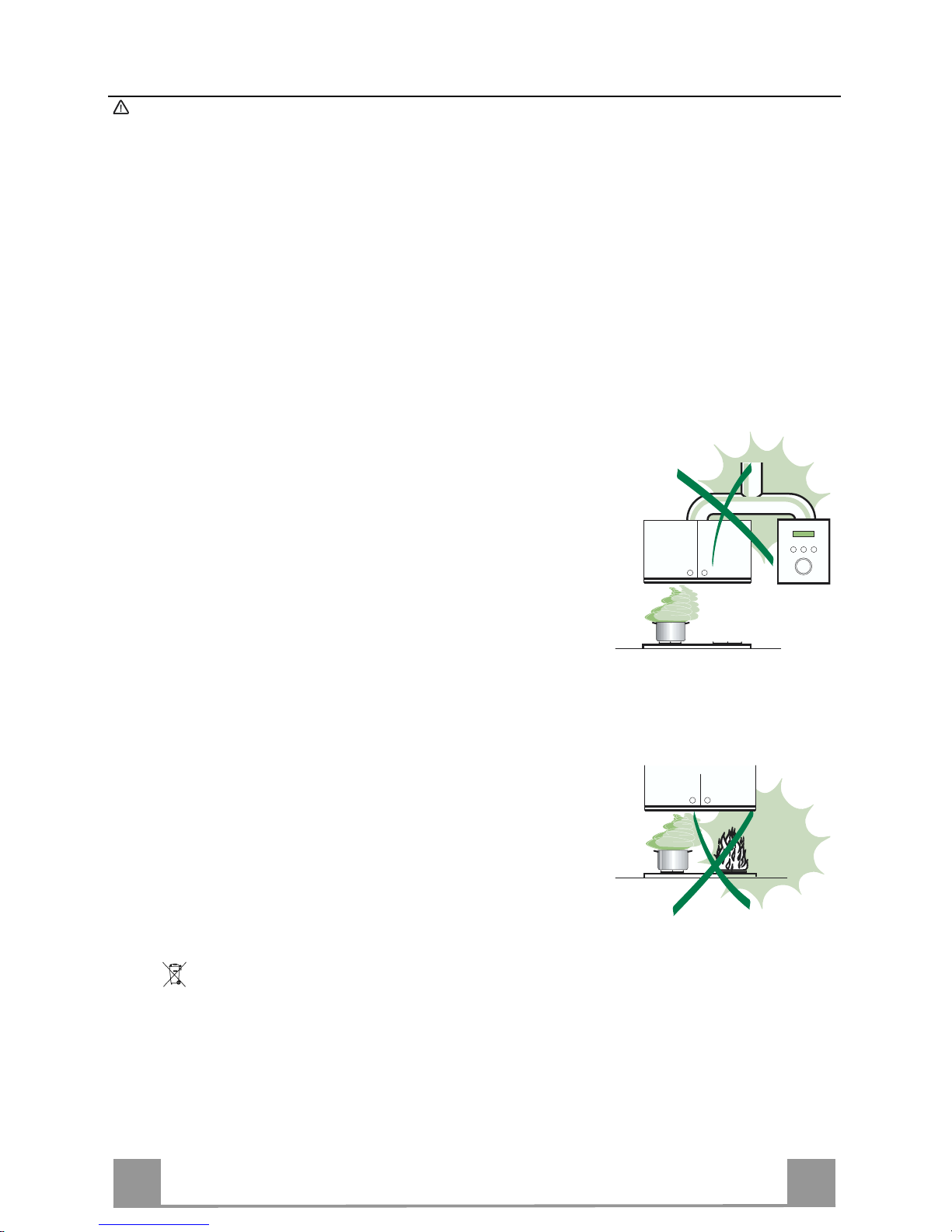
• Never lea ve high na ke d fla me s un de r the ho od wh en it i s in op er ati on .
• A djust th e flame intensity to direct it onto the bo ttom o f the pan only, m aki ng
sure that it does not engulf the sides.
• Deep fat fryers mus t be continuous ly monitored du ring use: over heated oil
can burst into flames.
• Do not flambè under the range hood; risk of fire
• This appliance is not intended for use by persons (incl uding children) with
reduced physi cal, sensory or m ental capabi lities, or lack o f experience an d
knowledge, unl ess th ey have been g iven su pervis ion o r instr ucti on con cern ing use of the appliance by a person responsible for their safety.
• Chi ldren should be s up ervised to ensur e that they do not pla y with t he appliance.
MAINTENANCE
• S wi tch of f or u nplug the appli an ce fr om the m ai ns s up pl y be fo re ca rr yi n g ou t
any maintenance work.
• Clean and/or replace the Filters after the specified time period (Fire hazard).
• Clean the hood using a damp cloth and a neutral liquid detergent.
The symbol on the product or on its packaging indicates that this product may not be treated
as household waste. Instead it shall be handed over to the applicable collection point for the
recycling of elec tr i cal and el ectronic eq uipment. By ensuring this product is di s p osed of c orrectly,
you will help prevent potential negative consequences for the environment and human health,
which could otherwise be caused by inappropriate waste handling of this product. For more
detailed information about recycling of this product, please contact your local city office, your
household waste disposal service or the shop where you purchased the product.
EN
4
4
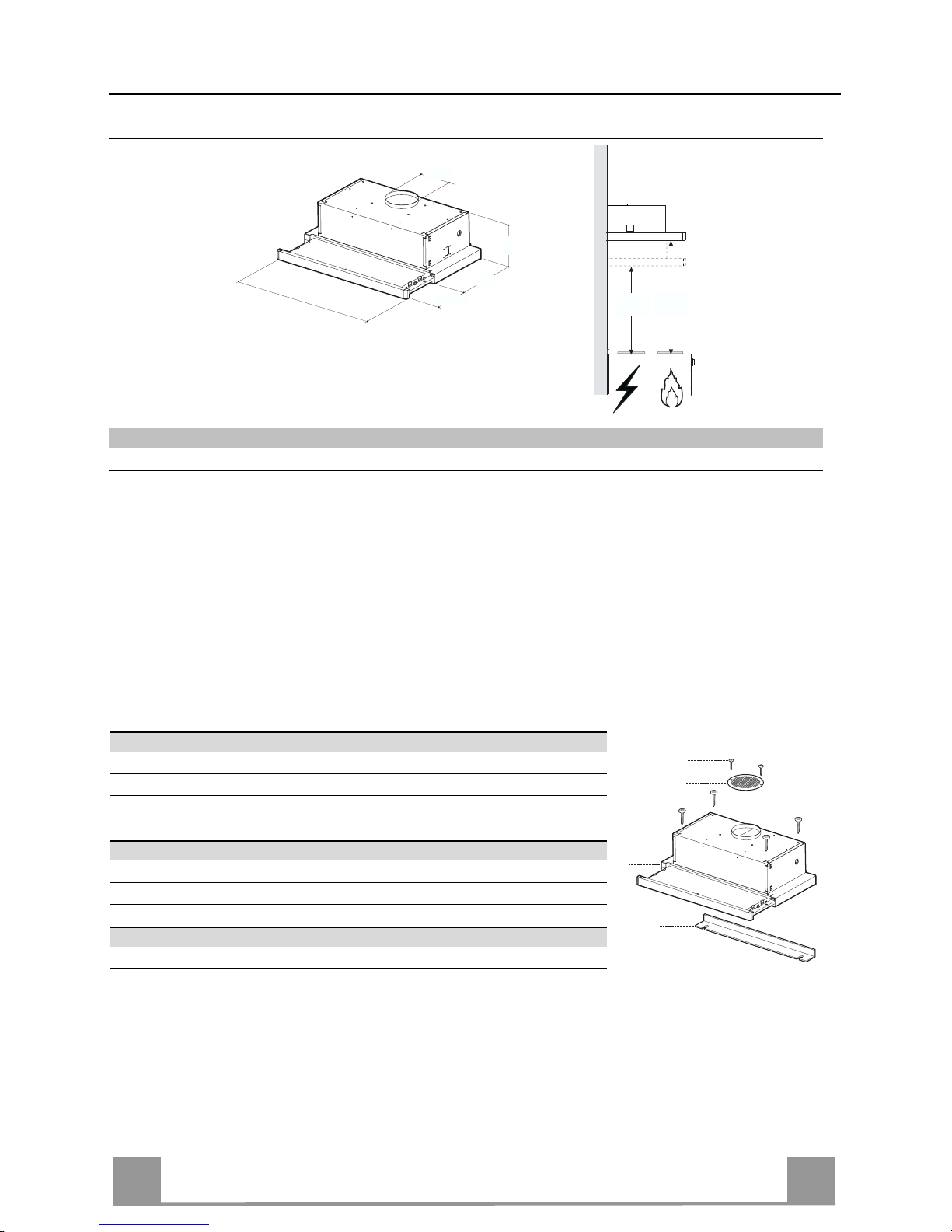
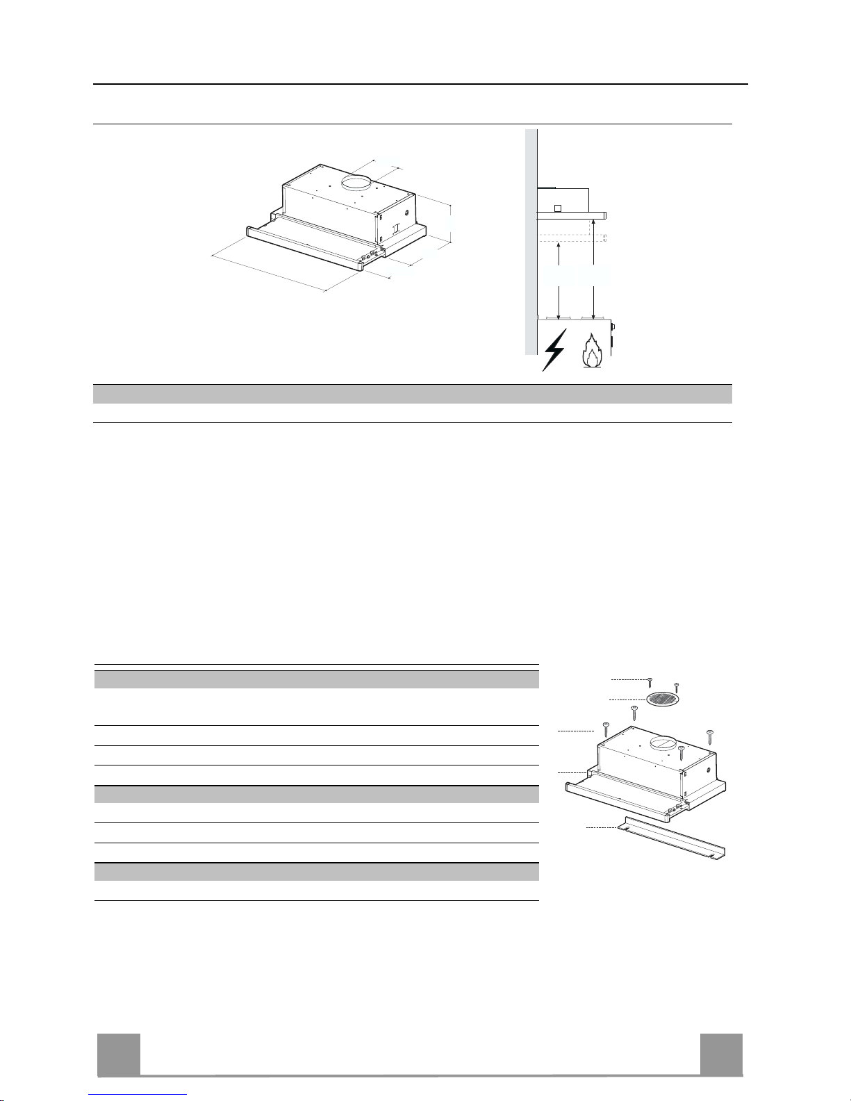
CHARACTERISTICS
Dimensions
0÷152
280
598 - 898
175
ø 120
Min.
650mm
Min.
650mm
Hood Type 45 50 55 60 70 80 90
L 448 498 548 598 698 798 898
Components
Ref. Q.ty Product Components
1 1 Hood Body, complete wit h: Controls, Light, Blow er, Filters
8 1 Directional Air Outlet grille
20 1 Closing element
Ref. Q.ty Installation Components
12a 4 Screws 4,2 x 44,4
12e 2 Screws 2,9 x 9,5
Q.ty Documentation
1 Instruction Manual
12e
8
1
12a
20

EN
5
5
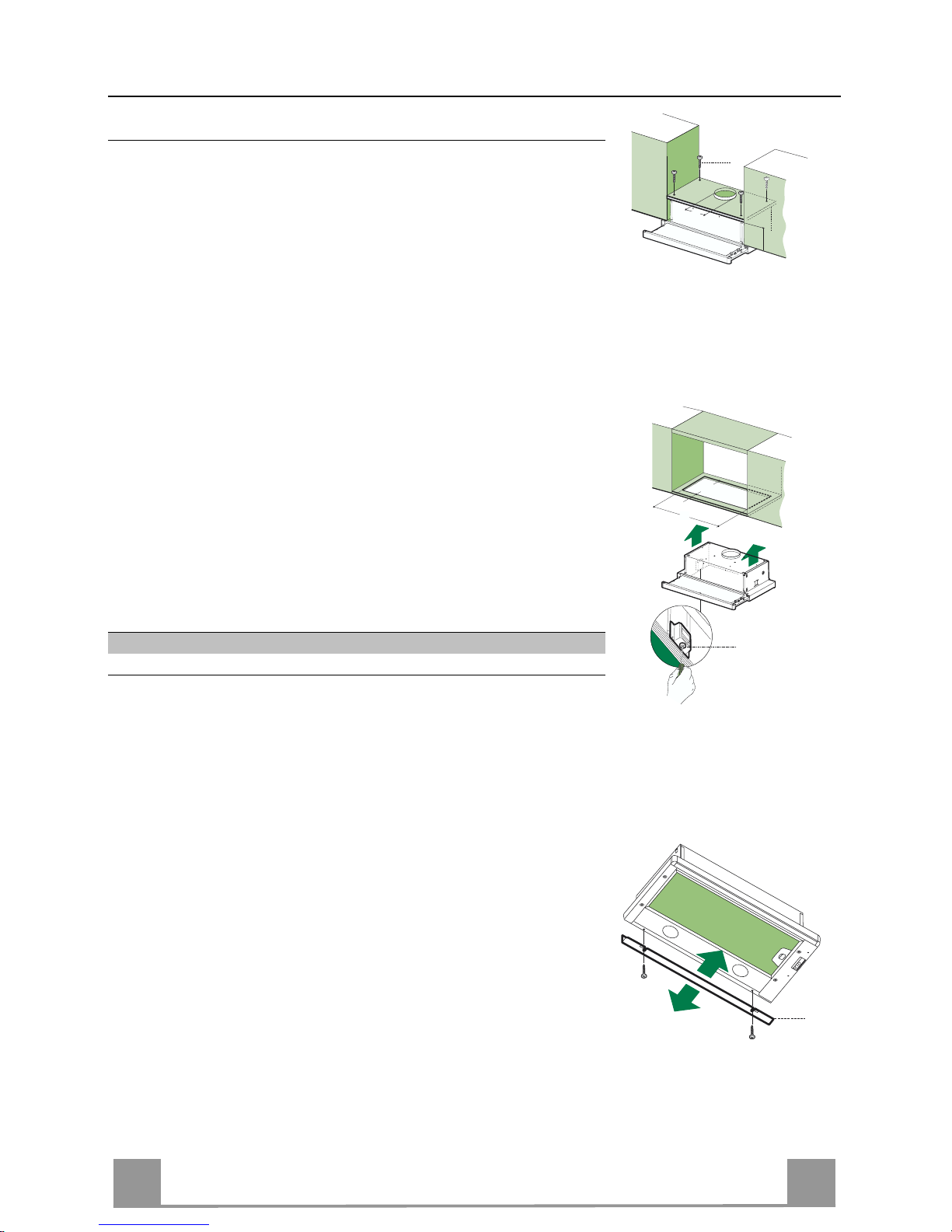
INSTALLATION
Drilling the Support surface and Fitting the Hood
SCREW FITTING
• The hood support surface must be 1 35 mm above the b ottom
surface of the wall units.
• Drill the support with a ø 4,5 mm drill bit, using the drilling
template provided.
• Cut a hole ø 125 mm in size on the suppo rt surface, using the
drilling template provided.
• Fix using th e 4 screws 12a (4,2 x 44,4) provided.
12a
135
125125
SNAP-ON FITTING
• The hood can be installed either directly on the bottom surface
of the wall units using snap-on side supports.
• Cu t a fitted opening in the bottom surface of the wall unit, as
shown.
• Insert the hood until the side supports snap into place.
• Lock in position by tightening the screws Vf from underneath
the hood.
Hood Type 45 50 55 60 70 80 90
L1 352 402 452 502 602 702 802
15
264
L1
Vf
CLOSING ELEMENT
• The space between th e edge of the hood and the rear wall can
be closed by applying the element 20 provided, using the
screws supplied for this purpose.
20
EN
6
6
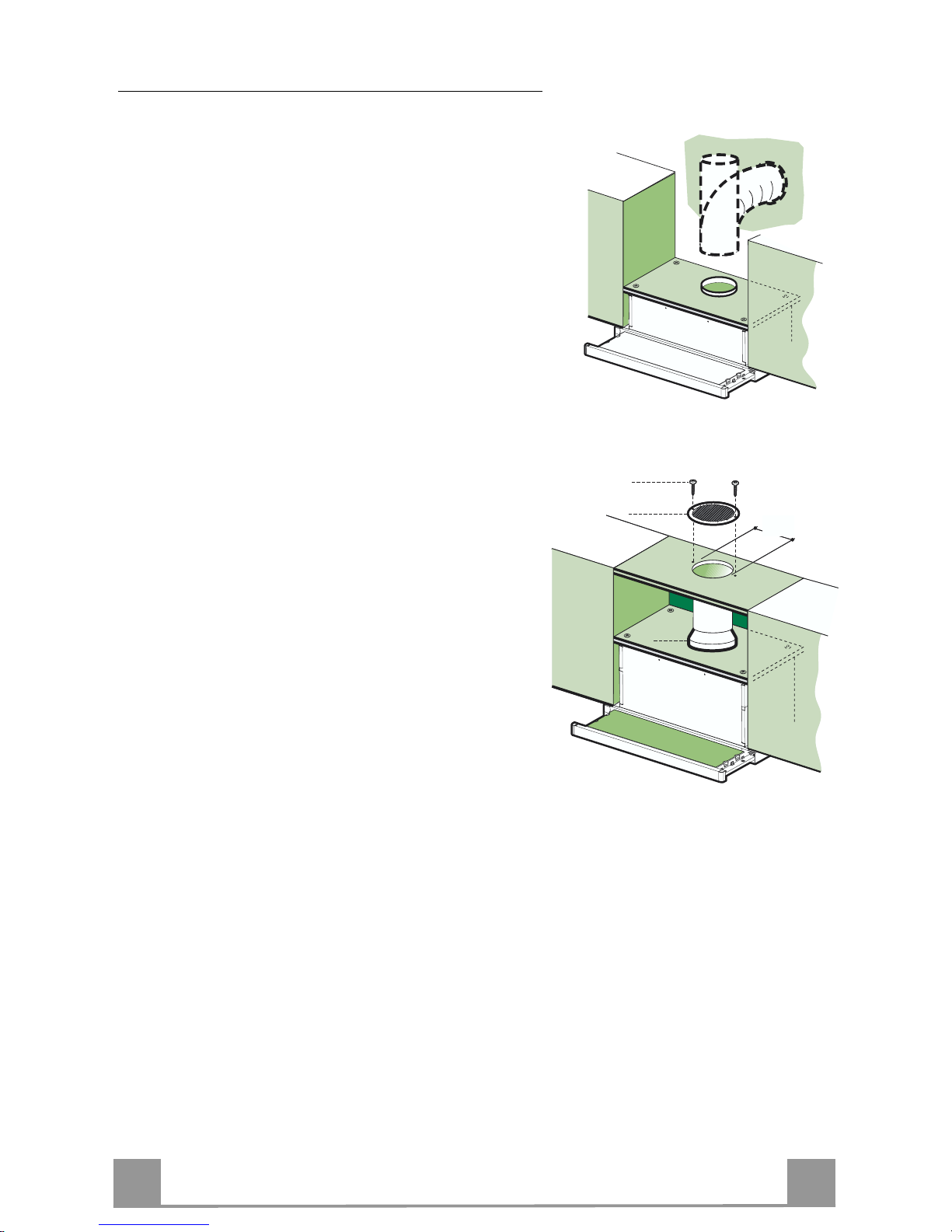
Connections
DUCTED VERSION AIR EXHAUST SYSTEM
When installing t he ducted versi on, conn ect the hood to
the chimney using either a flexible or rigid pipe ø120
mm, the choice of which is left to the installer.
• Fix the pipe in position using sufficient pipe clamps
(not supplied).
• Remove any activated charcoal filters.
ø 120
RECIRCULATION VERSION AIR OUTLET
• Cut a hole ø 125 mm in any shelf that may be positioned over the hood.
• Connect the flange to the outlet on the shelf over the
hood using a flexible or rigid pipe ø120 mm.
• Fix the pipe in position using sufficient pipe clamps
(not supplied).
• Fix the directional grille 8 on the recirculation air
outlet using the 2 screws 12e (2,9 x 9,5) provided.
• Ensure that the activated charcoal filters have been
inserted.
8
9
125
8
9
125
12e
ELECTRICAL CONNECTION
• Connect the hood to the mains through a two-pole switch having a contact gap of at least 3
mm.
• When opening the sliding carriage for the first time after installing the hood, pull it out
briskly until it clicks.
EN
7
7
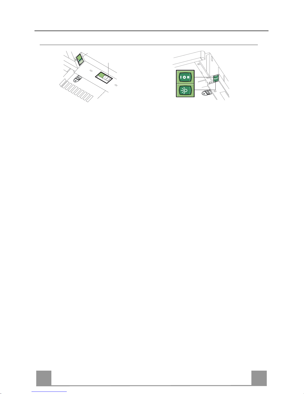
USE
Control panel
L Light Switches the lighting system
on and off.
M Motor Switches the extractor motor
on and off.
V Speed Sets the operati ng speed of
the extractor:
1. Low speed, used for a
continuous and silent air
change in the pr esence of
light cooking vapour.
2. Medium speed, suitable
for most operating conditions given the optimum
treated air flow/noise
level ratio.
3. Maximum speed , used for
eliminating the highest
cooking vapour emission,
including long periods.
L Light Switches the lighting system
on and off.
M Motor Switches the extractor motor
on and off.
V Speed Sets the operati ng speed of
the extractor:
1. Low speed, used for a
continuous and silent air
change in the pr esence of
light cooking vapour.
2. Medium speed, suitable
for most operating conditions given the optimum
treated air flow/noise
level ratio.
L
M - V
0
1
0
1
2
3
L
M-V
EN
8
8
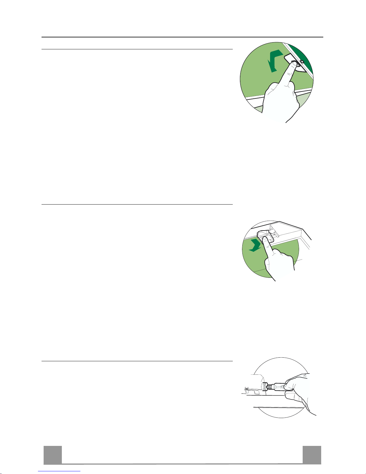
MAINTENANCE
Grease filters
CLEANING METAL CASSETTE GREASE FILTERS
• The filters must be cleaned every 2 months, or more frequently
in case of particularly heavy use of the hood. Filters can be
washed in a dishwasher.
• Pull out the sliding suction panel.
• Remove the filters one by one, after having disconnected the
relative fastening elements.
• Wash the filters, taking care not to bend them. Let them get dry
before refitting them. (The colour of the filter surface may
change throughout the time but this has no influence to the filter efficiency).
• When refitting the filters, make sure that the handle is visible
on the outside.
• Close the sliding su ction panel.
Charcoal filter (Recycling version)
REPLACING CHARCOAL FILT ERS
• These filters are not washable and cannot be regenerated, and
must be replaced approximately every four months or more
frequently by particularly heavy use.
• Pull out the sliding suction panel.
• Re move the grease filters.
• Remove the saturated carbon filter by releasing the fixing
hooks
• Replace the grease filters.
• Close the sliding su ction panel.
Lighting
LIGHT REPLACEMENT
40 W incandescent lig ht.
• Re move the metal grease filters.
• Unscrew the bu lbs and repl ace them with n ew ones having t he
same characteristics.
• Replace the metal grease filters.
EN
9
9
Lighting
LIGHT REPLACEMENT
20 W halogen light.
• Remove the 2 screws fixing the Lighting support, and pull it
out of from the Hood.
• Extract the lamp from the Support.
• Replace with another of the same type, making sure that the
two pins are properly inserted in the lamp holder socket holes.
• Replace the Support, fixing it in place with the two screws removed as above.
IT 110
CONSIGLI E SUGGERIMENTI
Questo libretto di istruzioni per l'uso è previsto per più versioni dell' appare
c
chio.
É possibile che siano descritti singoli particolari della dotazione, che non riguardano il Vostr o apparec c hio.
INSTALLAZIONE
• Il produttore declina qualsiasi responsabilità per danni dovuti ad installazione non
corretta o non c onfor me alle regole d ell’art e.
• La distanza minima di sicurezza tra il Piano di cottura e la Cappa deve essere di
650 mm, (alcuni modelli possono es ser e installati ad un’alt ezza inferiore, fare riferimento ai paragraf i ingo mbro e i ns tal laz ione) .
• Verificare che la tensione di rete corrisponda a quella riportata nella targhetta
posta all’interno della Cappa.
• P er Ap parecchi in Classe I
a
accertar si che l’impian to ele ttrico do mestico g aran ti-
sca un corr etto sc ar ic o a ter ra.
• Collegare la Cappa all’uscita dell’aria aspirata con tubazione di diametro pari o
superiore a 120 mm. Il percorso della tubazione deve essere il più breve possibile.
• Non collegare la Cappa a condotti di scarico dei fumi prodotti da combustione
(caldaie, c aminet t i, ec c.) .
• Nel caso in cui nella stanza vengano utilizzati sia la Cappa che apparecchi non
azionati da energia elettrica (ad esempio apparecchi utilizzatori di gas), si deve
provvedere ad una aerazione sufficiente dell’ambiente. Se la cucina ne fosse
sprovvista, praticare un’apertura che comunichi con l’esterno, per garantire il richiamo d’aria puli ta.
USO
• La Cappa è stata progettata esclusivamente per uso domestico, per abbattere gli
odori della cuc ina.
• Non fare mai uso impropr io del la Cap pa.
• Non lasciare fiamme l iber e a for te i ntens i tà sot to l a Cappa in f unzi one.
• Regolare sempre le fiamme in modo da evitare una evidente fuoriuscita laterale
delle stess e ri spet t o al fondo del le p ent ole.
• Controllare le fr iggi tr ici durant e l ’us o: l ’ol io surr isc aldat o pot rebb e inf i ammars i.
• Non preparare alim enti fl ambè sot t o la c appa da cuc i na; per ic ol o d'inc en dio.
• Q uesto ap parecchio non deve essere utilizzato da perso ne (ba mbini inclu si) con
ridotte capacità psichiche, sensoriali o mentali, oppure da persone senza esperienza e conoscenza, a meno che non siano controllati o istruiti all’uso
dell’apparecchio da per son e r esponsabili della loro sicurezza.
• I bambini devono essere supervisionati per assicurarsi che non giochino con
l’apparecchi o.
MANUTENZIONE
• Prima di procedere a qualsiasi operazione di manutenzione, disinserire la Cappa
togliendo la spina elettrica o spegnendo l’interruttore generale.
• Effettuare una scrupolosa e tempestiva manutenzione dei Filtri secondo gli intervalli consigliati (Rischio di incendio).
• Per la pulizia de lle su pe rfici d e lla C a ppa è suffi cie n te u tiliz za re u n pa nno um ido e
detersivo l iqui do neutr o.
Il simbolo sul prodotto o sulla confezione indica che il prodotto non deve essere considerato
come un no r m ale rifiuto domes t i c o , m a deve ess ere portato nel punto di raccolta a ppropriat o per
il rici cl aggi o di a ppar ecc hi at ur e el et tric he e d el ettr o nic he. P rov v edendo a smaltire questo prodotto in modo appropriato, si contribuisce a evitare potenziali conseguenze negative per l’ambiente
e per la salute, che potrebbero derivare da uno smaltimento inadeguato del prodotto. Per informazioni più dettagliate sul riciclaggio di questo prodotto, contattare l’ufficio comunale, il servizio
locale di smaltimento rif iut i o il negozio in cui è stato acqu istat o il prodot to .
IT 111
CARATTERISTICHE
Ingombro
0÷152
280
L
175
ø 120
Min.
650mm
Min.
650mm
Tipo Cappa 45 50 55 60 70 80 90
L 448 498 548 598 698 798 898
Componenti
Rif. Q.tà Componenti di Prodotto
1 1 Corpo Cappa completo di: Comandi, Luce, Gruppo Ventilatore,
Filtri
8 1 Griglia direzionata Uscita Aria
20 1 Profilo chiusura
Rif. Q.tà Componenti di Installazione
12a 4 Viti 4,2 x 44,4
12e 2 Viti 2,9 x 9, 5
Q.tà Documentazione
1 Libretto Istruzioni
12e
8
1
12a
20
IT 112
INSTALLAZIONE
Foratura Piano di supporto e Montaggio Cappa
MONTAGGIO CON VITI
• Il Piano di supporto della Cappa deve essere rientrante di 135
mm dal Piano inferiore dei Pensili.
• Forare ø 4,5 mm il supporto utilizzando la Dima di foratura in
dotazione.
• Praticare un foro ø 125 mm sul Piano d i supporto, utilizzando
la Dima di foratura in dotazione.
• Fissare con 4 Viti 12a (4,2 x 44,4) in dotazione.
12a
135
125125
MONTAGGIO CON FISSAGGIO A SCATTO
• La Cappa può essere installata direttamente sul piano inferiore
dei Pensili con i Supporti laterali a scatto.
• Praticare un incasso sul piano inferiore d el Pensile, come indicato.
• Inserire la Cappa fino ad agganciare i Supporti laterali a scatto.
• Bloccare definitivamente serrando le Viti Vf dal sotto della
Cappa.
Tipo Cappa 45 50 55 60 70 80 90
L1 352 402 452 502 602 702 802
15
264
L1
Vf
PROFILO DI CHIUSURA
• Lo spazio tra il bordo della Cappa e la Parete di fondo può essere chiuso applicando il Profilo 20 in dotazione con le Viti già
predisposte a questo scopo.
20
 Loading...