

Page 1
Instructions for use and installation
Istruzioni per l’uso e l’installazione
Mode d’emploi et installation
Bedienungsanleitung und Installation
Kullan
ım ve montaj talimatları
Instrukcja obsługi i instalacji
Інструкція
з
експлуатації
і
встановлення
Libret de Instruc
ţ
iuni
FTC 532L WH
FTB 60 XS V2
GB
Cooker Hood
IT
Cappa
FR
Hotte de Cuisine
DE
Dunstabzugshaube
TR
Davlumbaz
PL
Okap kuchenny
UK
Витяжка
ROI
Cartier
FTC 632L WH
FTC 632L BK
FTC 532L GR/XS
FTC 632L GR/XS
FTB 60 BK V2
FTB 60 WH V2
Page 2
INDEX
SAFETY INFORMATION ......................................................................................................................................................... 4
CHARACTERISTICS ............................................................................................................................................................. 7
INSTALLATION ...................................................................................................................................................................... 8
USE ...................................................................................................................................................................................... 10
MAINTENANCE ................................................................................................................................................................... 11
EN
INDICE
INFORMAZIONI SULLA SICUREZZA .................................................................................................................................... 13
CARATTERISTICHE ............................................................................................................................................................ 16
INSTALLAZIONE ................................................................................................................................................................. 17
USO ...................................................................................................................................................................................... 19
MANUTENZIONE................................................................................................................................................................. 20
IT
SOMMAIRE
CONSIGNES DE SÉCURITÉ ................................................................................................................................................. 22
CARACTERISTIQUES ......................................................................................................................................................... 25
INSTALLATION .................................................................................................................................................................... 26
UTILISATION ....................................................................................................................................................................... 28
ENTRETIEN ......................................................................................................................................................................... 29
FR
INHALTSVERZEICHNIS
SICHERHEITSINFORMATIONEN ......................................................................................................................................... 31
CHARAKTERISTIKEN ......................................................................................................................................................... 34
MONTAGE ........................................................................................................................................................................... 35
BEDIENUNG ........................................................................................................................................................................ 37
WARTUNG ........................................................................................................................................................................... 38
DE
IÇERIKLER
GÜVENLİK HAKKINDA BİLGİLER ......................................................................................................................................... 40
ÖZELLIKLER ........................................................................................................................................................................ 43
MONTAJ ............................................................................................................................................................................... 44
KULLANIM ........................................................................................................................................................................... 46
BAKIM .................................................................................................................................................................................. 47
TR
SPIS TREŚCI
INFORMACJE DOTYCZĄCE BEZPIECZEŃSTWA ................................................................................................................ 49
WŁAŚCIWOŚCI TECHNICZNE ........................................................................................................................................... 52
INSTALACJA ........................................................................................................................................................................ 53
UŻYTKOWANIE ................................................................................................................................................................... 55
KONSERWACJA.................................................................................................................................................................. 56
PL
2
2
Page 3

ІНДЕКС
ІНФОРМАЦІЯ З ТЕХНІКИ БЕЗПЕКИ .................................................................................................................................... 58
ХАРАКТЕРИСТИКИ ............................................................................................................................................................ 61
ВСТАНОВЛЕННЯ ............................................................................................................................................................... 62
ВИКОРИСТАННЯ ............................................................................................................................................................... 64
ОБСЛУГОВУВАННЯ ........................................................................................................................................................... 65
UA
CUPRINS
INFORMAŢII PRIVIND SIGURANŢA ...................................................................................................................................... 67
CARACTERISTICI ............................................................................................................................................................... 70
INSTALAREA ....................................................................................................................................................................... 71
UTILIZARE ........................................................................................................................................................................... 73
ÎNTREŢINERE ..................................................................................................................................................................... 74
RO
3
3
Page 4
EN
SAFETY INFORMATION
For your safety and correct operation of the appliance, read this manual
carefully before installation and use. Always keep these instructions
with the appliance even if you move or sell it. Users must fully know the
operation and safety features of the appliance.
The wire connection has to be done by specialized technician.
• The manufacturer will not be held liable for any damages resulting from
incorrect or improper installation.
• The minimum safety distance between the cooker top and the extractor
hood is 650 mm (some models can be installed at a lower height,
please refer to the paragraphs on working dimensions and installation).
• If the instructions for installation for the gas hob
distance, this must be respected.
• Check that the mains voltage corresponds to that indicated on the
rating plate fixed to the inside of the hood.
• Means for disconnection must be incorporated in the fixed wiring in
accordance with the wiring rules.
• For Class I appliances, check that the domestic power supply
guarantees adequate earthing.
• Connect the extractor to the exhaust flue through a pipe of minimum
diameter 120 mm. The route of the flue must be as short as possible.
• Regulations concerning the discharge of air have to be fulfilled.
• Do not connect the extractor hood to exhaust ducts carrying
combustion fumes (boilers, fireplaces, etc.).
specify a greater
4
4
Page 5
EN
•
If the extractor is used in conjunction with non-electrical appliances
(e.g. gas burning appliances), a sufficient degree of aeration must be
guaranteed in the room in order to prevent the backflow of exhaust gas.
When the cooker hood is used in conjunction with appliances supplied
with energy other than electric, the negative pressure in the room must
not exceed 0,04 mbar to prevent fumes being drawn back into the room
by the cooker hood.
• The air must not be discharged into a flue that is used for exhausting
fumes from appliances burning gas or other fuels.
• If the supply cord is damaged, it must be replaced from the manufac-
turer or its service agent.
• Connect the plug to a socket complying with current
regulations, locat-
ed in an accessible place.
• With regards to the technical and safety measures to be adopted for
fume discharging it is important to closely follow the regulations provided by the local authorities.
WARNING: Before installing the Hood, remove the protective films.
• Use only screws and small parts in support of the hood.
WARNING: Failure to install the screws or fixing device in accordance
with these instructions may result in electrical hazards.
• Do not look directly at the light through optical devices (binoculars,
magnifying glasses…).
• Do not flambè under the range hood; risk of fire.
• This appliance can be used by children aged from 8 years and above
and persons with reduced physical, sensory or mental capabilities or
lack of experience and knowledge if they have been given supervision
or instruction concerning use of the appliance in a safe way and understand the hazards involved. Children shall not play with the appliance.
Cleaning and user maintenance shall not be made by children without
supervision.
• Children should be supervised to ensure that they do
not play with the
appliance.
5
5
Page 6
EN
•
The appliance is not to be used by persons (including children) with reduced physical, sensory or mental capabilities, or lack of experience
and knowledge, unless they have been given supervision or instruction.
Accessible parts may become hot when used with cooking appliances.
• Clean and/or replace the Filters after the specified time period (Fire
hazard). See paragraph Care and Cleaning.
• There shall be adequate ventilation of the room when the range hood is
used at the same time as appliances burning gas or other fuels (not
applicable to appliances that only discharge the air back into the room).
• The symbol
on the product or on its packaging indicates that this
product may not be treated as household waste. Instead it shall be
handed over to the applicable collection point for the recycling of electrical and electronic equipment. By ensuring this product is disposed of
correctly, you will help prevent potential negative consequences for the
environment and human health, which could otherwise be caused by
inappropriate waste handling of this product. For more detailed information about recycling of this product, please contact your local city office, your household waste disposal service or the shop where you purchased the product.
6
6
Page 7
EN
CHARACTERISTICS
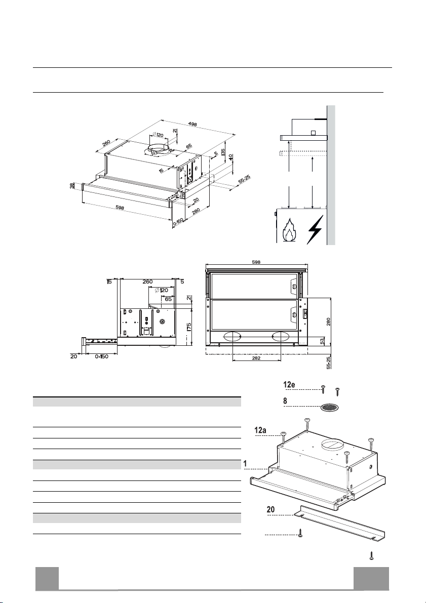
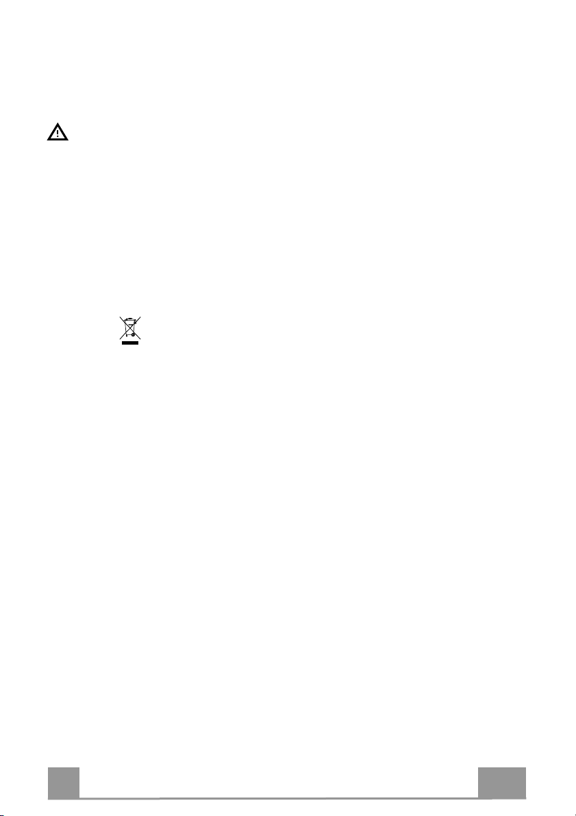
Dimensions
Min.
650mm
Min.
450mm
Components
Ref. Q.ty Product Components
1 1 Hood Body, complete with: Controls, Light, Blower,
Filters
8 1 Directional Air Outlet grille
20 1 Closing element
Ref. Q.ty Installation Components
12a 4 Screws 4,2 x 44,4
12b 2 Screws 4,2 x 12,7
12e 2 Screws 2,9 x 12,7
Q.ty Documentation
1 Instruction Manual
12b
7
7
Page 8
EN
INSTALLATION
12a
135
125125
15
262
L1
Vf
20
12b
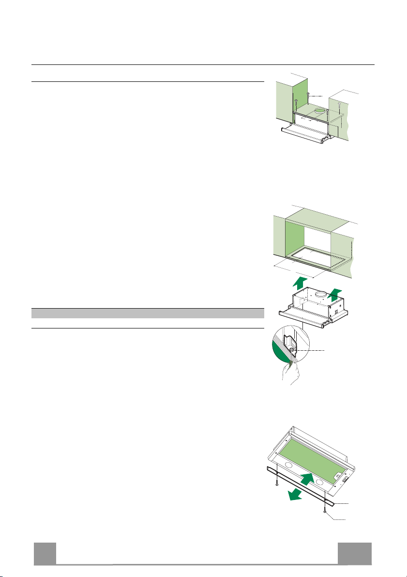
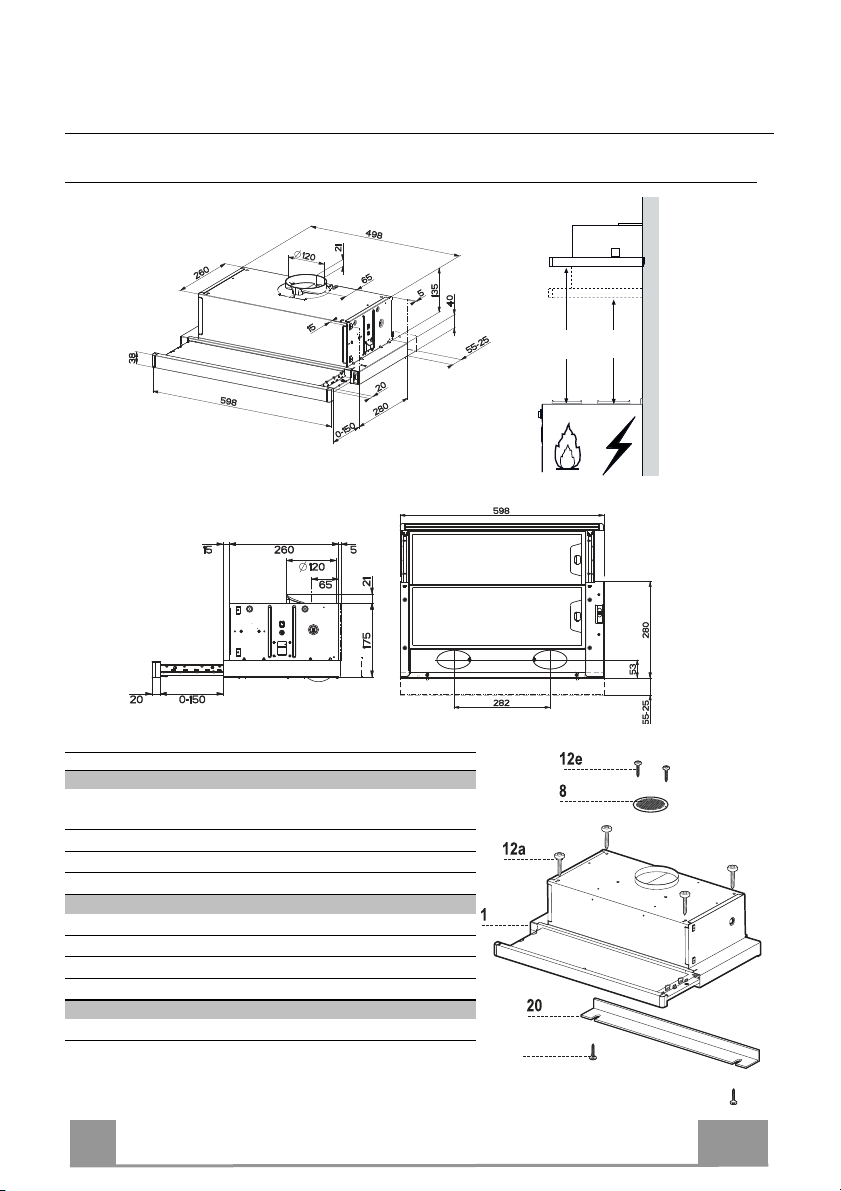
Drilling the Support surface and Fitting the Hood
SCREW FITTING
• The hood support surface must be 135 mm above the bottom
surface of the wall units.
• Drill the support with a ø 4,5 mm drill bit, using the drilling
template provided.
• Cut a hole ø 125 mm in size on the support surface, using the
drilling template provided.
• Fix using the 4 screws 12a (4,2 x 44,4) provided.
SNAP-ON FITTING
• The hood can be installed either directly on the bottom surface
of the wall units using snap-on side supports.
• Cut a fitted opening in the bottom surface of the wall unit, as
shown.
• Insert the hood until the side supports snap into place.
• Lock in position by tightening the screws Vf from underneath
the hood.
Hood Type 45 50 55 60 70 80 90
L1 360 410 460 510 610 710 810
CLOSING ELEMENT
• The space between the edge of the hood and the rear wall can
be closed by applying the element 20 provided, using the
screws 12b.
8
8
Page 9
EN
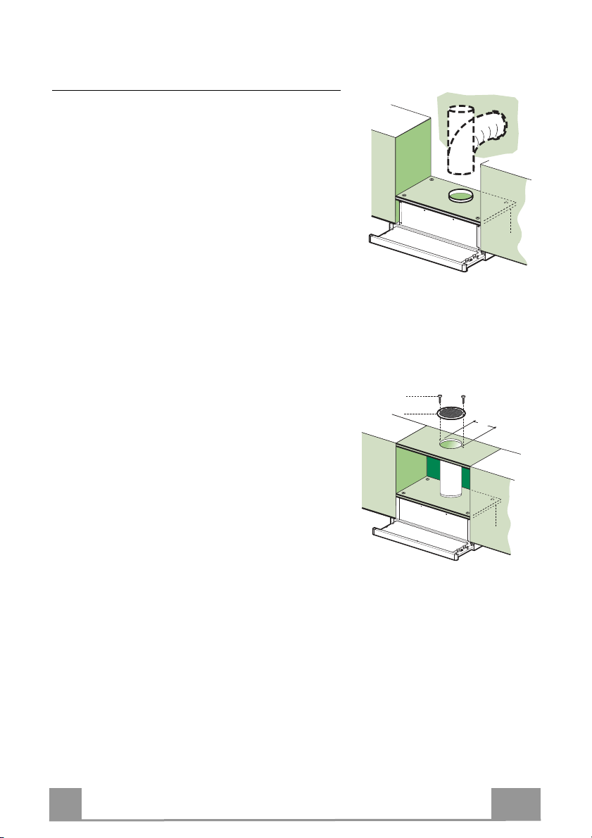
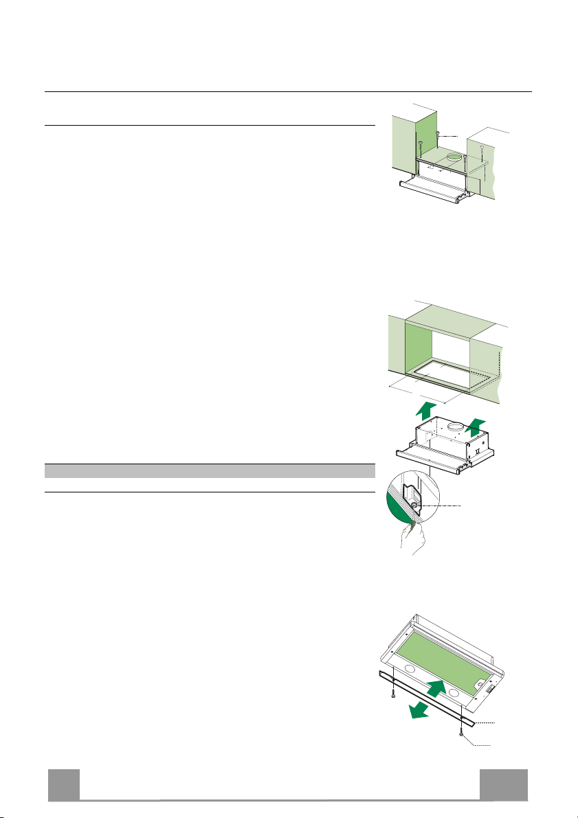
Connections
ø 120
12e
8
9
125
125
DUCTED VERSION AIR EXHAUST SYSTEM
When installing the ducted version, connect the hood to
the chimney using either a flexible or rigid pipe ø120
mm, the choice of which is left to the installer.
• Fix the pipe in position using sufficient pipe clamps
(not supplied).
• Remove any activated charcoal filters.
RECIRCULATION VERSION AIR OUTLET
• Cut a hole ø 125 mm in any shelf that may be positioned over the hood.
• Connect the flange to the outlet on the shelf over the
hood using a flexible or rigid pipe ø120 mm.
• Fix the pipe in position using sufficient pipe clamps
(not supplied).
• Fix the directional grille 8 on the recirculation air
outlet using the 2 screws 12e (2,9 x 9,5) provided.
• Ensure that the activated charcoal filters have been
inserted.
• Connect the hood to the mains through a two-pole switch having a contact gap of at least 3
mm.
• When opening the sliding carriage for the first time after installing the hood, pull it out
briskly until it clicks.
E
LECTRICAL CONNECTION
9
9
Page 10
EN 1
USE
L
L
L
M - V
0
1
0
1
2
3
L
M-V
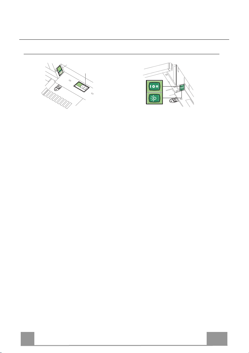
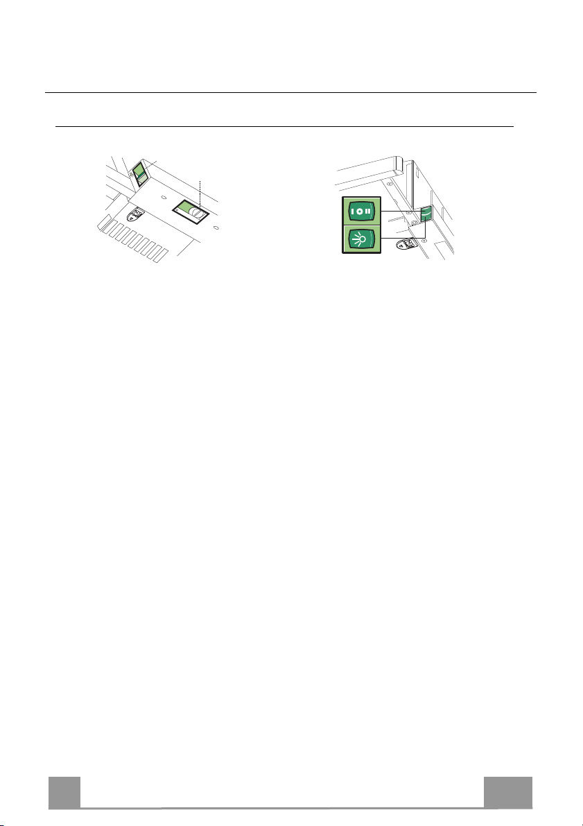
Control panel
Light Switches the lighting system
on and off.
M Motor Switches the extractor motor
on and off.
V Speed Sets the operating speed of
the extractor:
1. Low speed, used for a
continuous and silent air
change in the presence of
light cooking vapour.
2. Medium speed, suitable
for most operating conditions given the optimum
treated air flow/noise level ratio.
3. Maximum speed, used for
eliminating the highest
cooking vapour emission,
including long periods.
Light Switches the lighting system
on and off.
M Motor Switches the extractor motor
on and off.
V Speed Sets the operating speed of
the extractor:
1. Low speed, used for a
continuous and silent air
change in the presence of
light cooking vapour.
2. Medium speed, suitable
or most operating condi-
f
tions given the optimum
treated air flow/noise level ratio.
10
Page 11
EN 1
MAINTENANCE
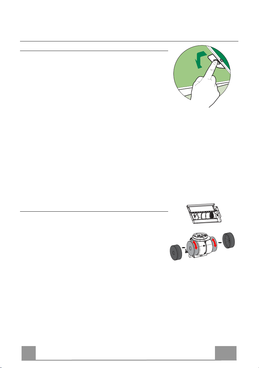
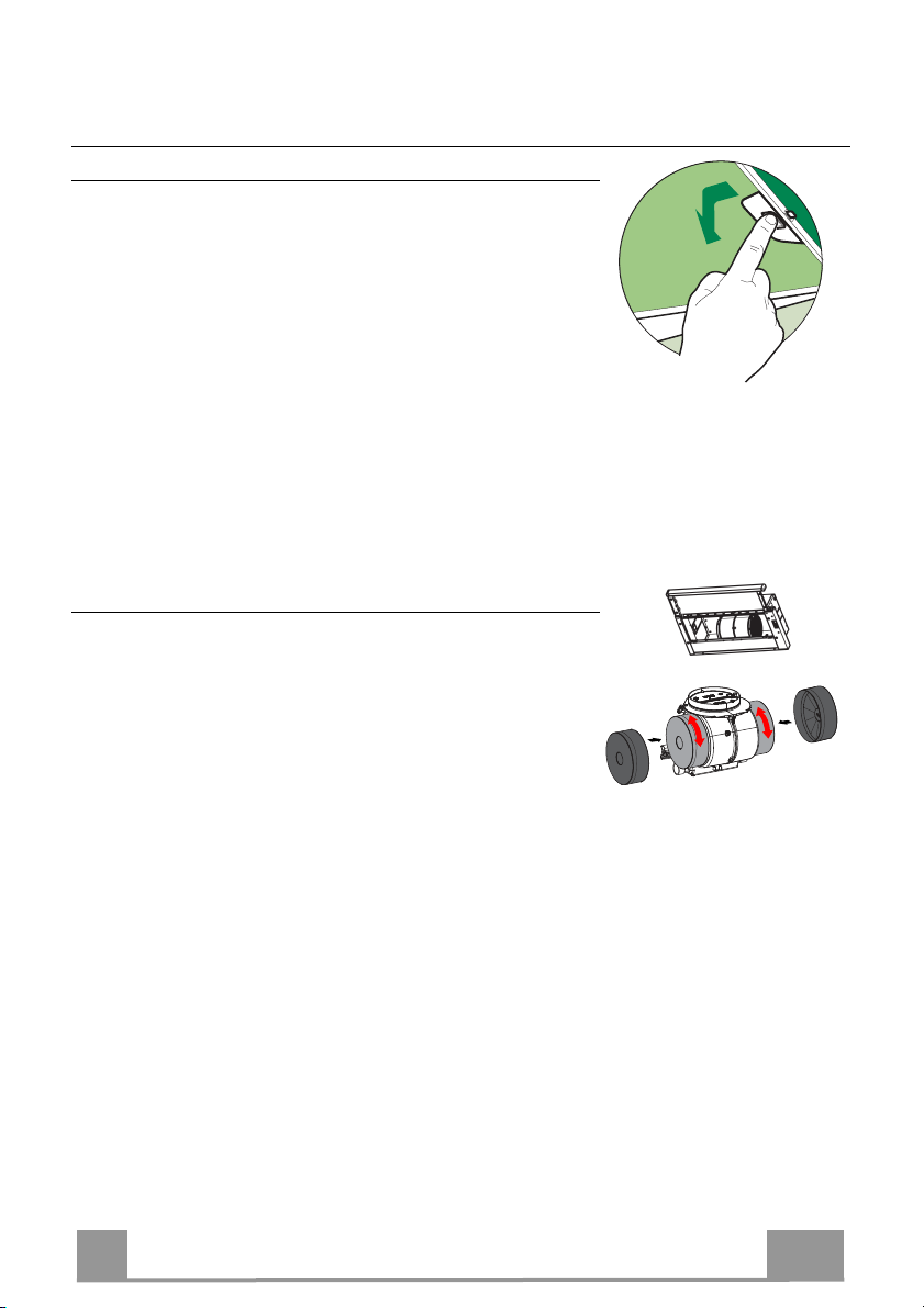
Grease filters
CLEANING METAL CASSETTE GREASE FILTERS
• The filters must be cleaned every 2 months, or more frequently
in case of particularly heavy use of the hood. Filters can be
washed in a dishwasher.
• Pull out the sliding suction panel.
• Remove the filters one by one, after having disconnected the
relative fastening elements.
• Wash the filters, taking care not to bend them. Let them get dry
before refitting them. (The colour of the filter surface may
change throughout the time but this has no influence to the filter efficiency).
• When refitting the filters, make sure that the handle is visible
on the outside.
• Close the sliding suction panel.
Charcoal filter (Recycling version)
REPLACING CHARCOAL FILTERS
Warning: Turn the lights off and wait until the lamps cool down
before you change the odour filter.
• These filters are not washable and cannot be regenerated, and
must be replaced approximately every four months or more
frequently by particularly heavy use.
• Pull out the sliding suction panel.
• Remove the grease filters.
• Remove the saturated carbon filter by releasing the fixing
hooks
• Fit the new filter by hooking it into its seating.
• Replace the grease filters.
• Close the sliding suction panel.
11
Page 12
EN 1
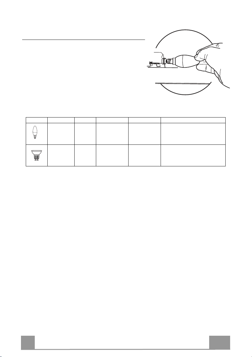
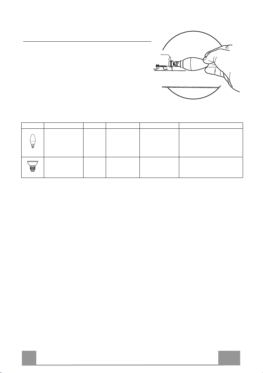
Lighting
LIGHT REPLACEMENT
• Remove the metal grease filters.
• Unscrew the bulbs and replace them with new ones
having the same characteristics.
• Replace the metal grease filters.
Lamp Power (W) Socket Voltage (V) Dimension (mm) ILCOS Code
4 E14 220-240 107 x 37 DRBB/F-4-220-240-E14-35/100
5 GU10 230 52 x 50
DRPAR-5/840-220/240-GU10-35/36
DRPAR-5/830-220/240-GU10-35/36
12
Page 13
IT 1
INFORMAZIONI SULLA SICUREZZA
Per la propria sicurezza e per il corretto funzionamento
dell’apparecchio, si prega di leggere attentamente questo manuale prima
dell’installazione e della messa in funzione. Tenere queste istruzioni
sempre insieme all’apparecchio, anche in caso di cessione o trasferimento
a terzi. È importante che gli utilizzatori conoscano tutte le caratteristiche di
funzionamento e sicurezza dell’apparecchio.
Il collegamento dei cavi deve essere effettuato da un tecnico competente.
• Il fabbricante non potrà ritenersi responsabile per eventuali danni risultanti da
un’installazione o utilizzazione impropria.
• La distanza minima di sicurezza tra il piano cottura e la cappa aspirante è di
650 mm (alcuni modelli possono essere installati a un’altezza inferiore;
vedere il paragrafo relativo alle dimensioni di lavoro e all’installazione).
• Se le istruzioni di installazione del piano cottura a gas specificano una
distanza maggiore di quella sopra indicata, è necessario tenerne conto.
• Controllare che la tensione di rete corrisponda a quella indicata sulla targa
dati applicata all’interno della cappa.
• I dispositivi di sezionamento devono essere installati nell’impianto fisso in
conformità alle normative sui sistemi di cablaggio.
• Per gli apparecchi di Classe I, controllare che la rete di alimentazione
domestica disponga di un adeguato collegamento a massa.
• Collegare la cappa alla canna fumaria con un tubo di diametro minimo di 120
mm. Il percorso dei fumi deve essere il più corto possibile.
• Devono essere rispettate tutte le normative riguardanti lo scarico dell’aria.
• Non collegare la cappa aspirante ai condotti fumari che trasportano fumi di
combustione (per es. di caldaie, camini ecc.).
13
Page 14

IT 1
•
Se la cappa è utilizzata in combinazione con apparecchi non elettrici (per es.
apparecchi a gas), deve essere garantito un sufficiente grado di aerazione nel
locale per impedire il ritorno di flusso dei gas di scarico. Quando la cappa per
cucina è utilizzata in combinazione con apparecchi non alimentati dalla
corrente elettrica, la pressione negativa nel locale non deve superare 0,04
mbar per evitare che i fumi vengano riaspirati nel locale dalla cappa.
• L’aria non deve essere evacuata attraverso un condotto utilizzato per lo
scarico dei fumi da apparecchi di combustione alimentati a gas o altri
combustibili.
• Il cavo di alimentazione, se danneggiato, deve essere sostituito dal
fabbricante o da un tecnico del servizio assistenza.
• Collegare la spina ad una presa di tipo conforme alle normative vigenti e in
posizione accessibile.
• Relativamente alle misure tecniche e di sicurezza da adottare per lo scarico
dei fumi è importante attenersi scrupolosamente ai regolamenti stabiliti dalle
autorità locali.
AVVERTENZA: prima di installare la cappa, rimuovere le pellicole di
protezione.
• Usare solo viti e minuteria di tipo idoneo per la cappa.
AVVERTENZA: la mancata installazione delle viti o dei dispositivi di
fissaggio in conformità alle presenti istruzioni può comportare rischi di
scosse elettriche.
• Non osservare direttamente con strumenti ottici (binocolo, lente
d’ingrandimento….).
• Non cuocere al flambé sotto la cappa: si potrebbe sviluppare un incendio.
• Questo apparecchio può essere utilizzato da bambini di età non inferiore a 8
anni e da persone con ridotte capacità psico-fisico-sensoriali o con
esperienza e conoscenze insufficienti, purché attentamente sorvegliati e
istruiti su come utilizzare in modo sicuro l’apparecchio e sui pericoli che ciò
comporta. Assicurarsi che i bambini non giochino con l’apparecchio. Pulizia e
manutenzione da parte dell’utente non devono essere effettuate da bambini,
a meno che non siano sorvegliati.
• Sorvegliare i bambini, assicurandosi che non giochino con l’apparecchio.
14
Page 15
IT 1
•
L’apparecchio non deve essere utilizzato da persone (bambini compresi) con
ridotte capacità psico-fisico-sensoriali o con esperienza e conoscenze
insufficienti, a meno che non siano attentamente sorvegliate e istruite.
Le parti accessibili possono diventare molto calde durante l’uso degli
apparecchi di cottura.
• Pulire e/o sostituire i filtri dopo il periodo di tempo specificato (pericolo di
incendio). Vedere il paragrafo Manutenzione e pulizia.
• Deve essere presente un’adeguata ventilazione nel locale quando la cappa
è utilizzata contemporaneamente ad apparecchi che utilizzano gas o altri
combustibili (non applicabile ad apparecchi che scaricano unicamente l’aria
nel locale).
• Il simbolo
sul prodotto o sulla sua confezione indica che il prodotto non
può essere smaltito come un normale rifiuto domestico. Il prodotto da
smaltire deve essere conferito presso un apposito centro di raccolta per il
riciclaggio dei componenti elettrici ed elettronici. Assicurandosi che questo
prodotto sia smaltito correttamente, si contribuirà a prevenire potenziali
conseguenze negative per l’ambiente e per la salute che potrebbero
altrimenti derivare dal suo smaltimento inadeguato. Per informazioni più
dettagliate sul riciclaggio di questo prodotto, contattare il Comune, il servizio
locale di smaltimento rifiuti oppure il negozio dove è stato acquistato il
prodotto.
15
Page 16
IT 1
CARATTERISTICHE
Ingombro
Min.
650mm
Min.
450mm
Componenti
Rif. Q.tà Componenti di Prodotto
1 1 Corpo Cappa completo di: Comandi, Luce, Gruppo
8 1 Griglia direzionata Uscita Aria
20 1 Profilo chiusura
Rif. Q.tà Componenti di Installazione
12a 4 Viti 4,2 x 44,4
12b 2 Viti 4,2 x 12,7
12e 2 Viti 2,9 x 12,7
Ventilatore, Filtri
Q.tà Documentazione
1 Libretto Istruzioni
12b
16
Page 17
IT 1
INSTALLAZIONE
12a
135
125125
15
262
L1
Vf
20
12b
Foratura Piano di supporto e Montaggio Cappa
MONTAGGIO CON VITI
• Il Piano di supporto della Cappa deve essere rientrante di 135
mm dal Piano inferiore dei Pensili.
• Forare ø 4,5 mm il supporto utilizzando la Dima di foratura in
dotazione.
• Praticare un foro ø 125 mm sul Piano di supporto, utilizzando
la Dima di foratura in dotazione.
• Fissare con 4 Viti 12a (4,2 x 44,4) in dotazione.
MONTAGGIO CON FISSAGGIO A SCATTO
• La Cappa può essere installata direttamente sul piano inferiore
dei Pensili con i Supporti laterali a scatto.
• Praticare un incasso sul piano inferiore del Pensile, come indicato.
• Inserire la Cappa fino ad agganciare i Supporti laterali a scatto.
• Bloccare definitivamente serrando le Viti Vf dal sotto della
Cappa.
Tipo Cappa 45 50 55 60 70 80 90
L1 360 410 460 510 610 710 810
• Lo spazio tra il bordo della Cappa e la Parete di fondo può essere chiuso applicando il Profilo 20 in dotazione con le Viti
PROFILO DI CHIUSURA
12b.
17
Page 18
IT 1
Connessioni
ø 120
12e
8
9
125
125
USCITA ARIA VERSIONE ASPIRANTE
Per installazione in Versione Aspirante collegare la
Cappa alla tubazione di uscita per mezzo di un tubo
rigido o flessibile di ø120 mm, la cui scelta è lasciata
all'installatore.
• Fissare il tubo con adeguate fascette stringitubo. Il
materiale occorrente non è in dotazione.
• Togliere eventuali Filtri Antiodore al Carbone attivo.
USCITA ARIA VERSIONE FILTRANTE
• Praticare un foro ø 125 mm sull’eventuale Mensola
soprastante la Cappa.
• Collegare la Flangia al foro di uscita sulla Mensola
soprastante la Cappa con un tubo rigido o flessibile di
ø120 mm.
• Fissare il tubo con adeguate fascette stringitubo. Il
materiale occorrente non è in dotazione.
• Fissare la Griglia direzionata 8 sull’uscita con 2 Viti
12e (2,9 x 9,5) in dotazione.
• Assicurarsi della presenza dei Filtri antiodore al Carbone attivo.
• Collegare la Cappa all’Alimentazione di Rete interponendo un Interruttore bipolare con
apertura dei contatti di almeno 3 mm.
• Dopo aver installato la cappa è necessario per la prima volta aprire il carrello scorrevole
energicamente fino a sentire lo scatto di fine corsa.
CONNESSIONE ELETTRICA
18
Page 19
IT 1
USO
L
L
L
M - V
0
1
0
1
2
3
L
M-V
Quadro comandi
Luci Accende e spegne l’Impianto
di Illuminazione.
M Motore Accende e spegne il motore
Aspirazione.
V Velocità Determina la velocità di
esercizio:
1. Velocità minima, adatta
ad un ricambio d’aria
continuo particolarmente
silenzioso, in presenza di
pochi vapori di cottura.
2. Velocità media, adatta
alla maggior parte delle
condizioni d’uso, dato
l’ottimo rapporto tra portata d’aria trattata e livello sonoro.
3. Velocità massima, adatta
a fronteggiare le massime
emissioni di vapore di
cottura, anche per tempi
prolungati.
Luci Accende e spegne l’Impianto
di Illuminazione.
M Motore Accende e spegne il motore
Aspirazione.
V Velocità Determina la velocità di
esercizio:
1. Velocità minima, adatta
ad un ricambio d’aria
continuo particolarmente
silenzioso, in presenza di
pochi vapori di cottura.
2. Velocità media, adatta alla
maggior parte delle condizioni d’uso, dato
l’ottimo rapporto tra portata d’aria trattata e livello
sonoro.
19
Page 20
IT 2
MANUTENZIONE
Filtri antigrasso
PULIZIA FILTRI ANTIGRASSO METALLICI AUTOPORTANTI
• Sono lavabili anche in lavastoviglie, e necessitano di essere
lavati ogni 2 mesi circa di utilizzo o più frequentemente, per un
uso particolarmente intenso.
• Estrarre il carrello aspirante.
• Togliere i Filtri uno alla volta, agendo sugli appositi agganci.
• Lavare i Filtri evitando di piegarli, e lasciarli asciugare prima
di rimontarli. (Un’eventuale cambiamento del colore della superficie del filtro, che potrebbe verificarsi nel tempo, non pregiudica assolutamente l’efficienza dello stesso.)
• Rimontarli facendo attenzione a mantenere la maniglia verso la
parte visibile esterna.
• Chiudere il carrello aspirante.
Filtri antiodore (Versione Filtrante)
SOSTITUZIONE
Attenzione: Spegnere le luci ed attendere il raffreddamento delle
lampade prima di effettuare la sostituzione del filtro antiodore.
• Non sono lavabili né rigenerabili, vanno sostituiti ogni 4 mesi
circa di utilizzo o più frequentemente, per un uso particolarmente intenso.
• Estrarre il carrello aspirante.
• Togliere i Filtri Antigrasso
• Rimuovere il Filtro antiodore al Carbone attivo saturo, agendo
sugli appositi agganci.
• Rimontare i Filtri antigrasso.
• Richiudere il carrello aspirante.
20
Page 21
IT 2
Illuminazione
SOSTITUZIONE LAMPADE
• Togliere i Filtri antigrasso metallici.
• Svitare le Lampade e sostituirle con nuove di uguali
caratteristiche.
• Rimontare i Filtri antigrasso metallici.
Lampada Assorbimento (W) Attacco Voltaggio (V) Dimensione (mm) Codice ILCOS
4 E14 220 – 240 107 x 37
5 GU10 230 52 x 50
DRBB/F-4-220-240-E14-35/100
DRPAR-5/840-220/240-GU10-35/36
DRPAR-5/830-220/240-GU10-35/36
21
Page 22
FR 2
CONSIGNES DE SÉCURITÉ
Pour votre sécurité et pour garantir le fonctionnement correct de
l’appareil, veuillez lire attentivement ce manuel avant d’installer et de
mettre en fonction l’appareil. Toujours conserver ces instructions avec
l’appareil, même en cas de cession ou de transfert à une autre personne.
Il est important que les utilisateurs connaissent toutes les caractéristiques
de fonctionnement et de sécurité de l’appareil.
La connexion des câbles doit être effectuée par un technicien compétent.
• En aucun cas le fabricant ne peut être tenu pour responsable d’éventuels
dommages dus à une installation ou à une utilisation impropre.
• La distance de sécurité minimum entre le plan de cuisson et la hotte
aspirante est de 650 mm (certains modèles peuvent être installés à une
hauteur inférieure ; voir le paragraphe concernant les dimensions de travail
et l’installation).
• Si les instructions d’installation du plan de cuisson à gaz spécifient une
distance supérieure à celle indiquée ci-dessus, veuillez impérativement en
tenir compte.
• Assurez-vous que la tension du secteur correspond à celle indiquée sur la
plaque des caractéristiques apposée à l’intérieur de la hotte.
• Les dispositifs de sectionnement doivent être montés dans l’installation fixe
conformément aux normes sur les systèmes de câblage.
• Pour les appareils de Classe I, s’assurer que l’installation électrique de
votre intérieur dispose d’une mise à la terre adéquate.
• Reliez l’aspirateur du conduit de cheminée avec un tube ayant un diamètre
minimum de 120 mm. Le parcours des fumées doit être le plus court
possible.
• Respecter toutes les normes concernant l’évacuation de l’air.
• Ne reliez pas la hotte aspirante aux conduits de cheminée qui acheminent
les fumées de combustion (par ex. de chaudières, de cheminées, etc.).
22
Page 23
FR 2
•
Si vous utilisez l’aspirateur en même temps que des appareils non électriques
(par ex. fonctionnant au gaz), veillez à ce que la pièce soit adéquatement
ventilée, afin d’empêcher le retour du flux des gaz d’évacuation. Si vous utilisez la
hotte de cuisine en même temps que des appareils non alimentés à l’électricité, la
pression négative dans la pièce ne doit pas dépasser 0,04 mbar, afin d’éviter que
les fumées soient réaspirées dans la pièce où se trouve la hotte.
• Ne pas évacuer l’air à travers une conduite utilisée pour l’évacuation des fumées
des appareils de combustion alimentés au gaz ou avec d’autres combustibles.
• Si le cordon d’alimentation est endommagé, faites-le remplacer par le fabricant ou
par un technicien d’un service après-vente agréé.
• Branchez la fiche à une prise conforme aux normes en vigueur et dans une
position accessible.
• En ce qui concerne les dimensions techniques et de sécurité à adopter pour
l’évacuation des fumées, veuillez vous conformer scrupuleusement aux
règlements établis par les autorités locales.
AVERTISSEMENT : Avant d’installer la hotte, retirer les films de protection.
• Utilisez exclusivement des vis et des petites fournitures du type adapté pour la
hotte.
AVERTISSEMENT toute installation de vis et de dispositifs de fixation non
conformes à ces instructions peut entraîner des risques de décharges
électriques.
• Ne pas observer directement avec des instruments optiques (jumelles, lentilles
grossissantes...).
• Ne flambez pas des mets sous la hotte : sous risque de développer un incendie.
• Cet appareil peut être utilisé par des enfants de plus de 8 ans et par des
personnes dont les capacités physiques, sensorielles ou mentales sont
diminuées ou ayant une expérience et des connaissances insuffisantes, pourvu
que ce soit sous la surveillance attentive d’une personne responsable et après
avoir reçu des instructions sur la manière d’utiliser cet appareil en toute sécurité et
sur les dangers que cela comporte. Assurez-vous que les enfants ne jouent pas
avec cet appareil. Le nettoyage et l’entretien de la part de l’utilisateur ne doivent
pas être effectués par des enfants, à moins qu’ils ne soient surveillés.
• Surveillez les enfants. S’assurer qu’ils ne jouent pas avec l’appareil.
23
Page 24

FR 2
•
Cet appareil n’est pas destiné à être utilisé par des personnes (enfants
compris) dont les capacités physiques, sensorielles ou mentales sont
diminuées ou ayant une expérience et des connaissances insuffisantes, à
moins que celles-ci ne soient attentivement surveillées et instruites.
Les parties accessibles peuvent devenir très chaudes durant l’utilisation
des appareils de cuisson.
• Nettoyer et/ou remplacer les filtres après le délai indiqué (danger
d’incendie). Voir le paragraphe Nettoyage et Entretien.
• Veillez à ce que la pièce bénéficie d’une ventilation adéquate lorsque la
hotte fonctionne en même temps que des appareils utilisant du gaz ou
d’autres combustibles (non applicable aux appareils qui évacuent l’air
uniquement dans la pièce).
• Le symbole marqué sur le produit ou sur son emballage indique que ce
produit ne peut pas être éliminé comme déchet ménager normal. Lorsque
ce produit doit être éliminé, veuillez le remettre à un centre de collecte
prévu pour le recyclage du matériel électrique et électronique. En vous
assurant que cet appareil est éliminé correctement, vous participez à
prévenir des conséquences potentiellement négatives pour l'environnement
et pour la santé, qui risqueraient de se présenter en cas d’élimination
inappropriée. Pour toute information supplémentaire sur le recyclage de ce
produit, contactez votre municipalité, votre déchetterie locale ou le magasin
où vous avez acheté ce produit.
24
Page 25

FR 2
CARACTERISTIQUES
Encombrement
Min.
650mm
Min.
450mm
Composants
Réf. Q.té Composants de Produit
1 1 Corps Hotte équipé de:Commandes, Lumière, Groupe
8 1 Grille orientée Sortie de l ’Air
20 1 Profil fermeture
Réf. Q.té Composants pour l ’installation
12a 4 Vis 4,2 x 44,4
12b 2 Vis 4,2 x 12,7
12e 2 Vis 2,9 x 12,7
Ventilateur, Filtres
Q.té Documentation
1 Manuel d’instructions
12b
25
Page 26

FR 2
INSTALLATION
12a
135
125125
15
262
L1
Vf
20
12b
Perçage du Plan de support et Montage de la Hotte
MONTAGE AU MOYEN DE VIS
• Le Plan de support de la Hotte doit être monté plus en haut de
135 mm. par rapport au Plan inférieur des Armoires murales.
• Percer un trou de ø 4,5 mm. sur le support, en utilisant le Gabarit de perçage fourni avec l’appareil.
• Percer un trou de ø 125 mm. sur le Plan de support, en utilisant
le Gabarit de perçage fourni avec l’appareil.
• Fixer à l’aide des 4 Vis 12a (4,2 x 44,4) fournies avec
l’appareil.
MONTAGE AVEC FIXATION PAR ENCLIQUETAGE
• Il est possible d’installer la Hotte directement sur le plan inférieur des Armoires murales au moyen de supports latéraux par
encliquetage.
• Effectuer un emboîtage sur le plan inférieur de l’Armoire murale, comme indiqué.
• Insérer la Hotte jusqu’à accrocher les Supports latéraux par
encliquetage.
• Bloquer définitivement en serrant les Vis Vf depuis le bas de la
Hotte.
Hotte Type 45 50 55 60 70 80 90
L1 360 410 460 510 610 710 810
• Il est possible de boucher l’espace entre le rebord de la Hotte et
PROFIL DE FERMETURE
la Paroi du fond, en appliquant le Profil 20 fourni avec
l’appareil avec les Vis 12b.
26
Page 27

FR 2
Branchements
ø 120
12e
8
9
125
125
SORTIE AIR VERSION EVACUATION
En cas d’installation en version évacuation, brancher la
hotte à la tuyauterie de sortie via un tube rigide ou
flexible de ø 120 mm, au choix de l’installateur.
• Fixer le tube par des colliers appropriés. Le matériau
nécessaire n’est pas fourni.
• Retirer les éventuels filtres anti-odeur au charbon
actif.
SORTIE AIR VERSION RECYCLAGE
• Percer un trou de ø 125 mm. sur l’éventuelle Tablette
qui se trouve au-dessus de la Hotte.
• Connecter la Flasque au trou de sortie sur la Tablette
qui se trouve au-dessus de la Hotte, au moyen d’un
tuyau rigide ou flexible de ø120 mm.
• Fixer le tube par des colliers appropriés. Le matériau
nécessaire n’est pas fourni.
• Fixer la Grille orientée 8 sur la sortie de l’air recyclé
à l’aide de 2 Vis 12e (2,9 x 9,5) fournies avec
l’appareil.
• S’assurer de la présence des filtres anti-odeur au
charbon actif.
• Brancher la hotte sur le secteur en interposant un interrupteur bipolaire avec ouverture des
contacts d’au moins 3 mm.
• Après avoir installé la hotte, il est indispensable pour la première fois d’ouvrir le chariot
coulissant de façon énergique, jusqu’à ce que l’on entende le déclic de fin de course.
BRANCHEMENT ELECTRIQUE
27
Page 28

FR 2
UTILISATION
L
L
L
M-V
L
M - V
0
1
0
1
2
3
Tableau de commande
Lumières Allume et éteint l’éclairage.
M Moteur Allume et éteint le moteur
aspiration.
V Vitesses Détermine les vitesses
d’exploitation ainsi subdivisées:
1. Vitesse minimale, pour
un rechange d’air permanent particulièrement silencieux en cas de faibles
vapeurs de cuisson.
2. Vitesse moyenne pour la
plupart des conditions
d’utilisation, étant donné
le rapport optimal entre
débit d’air traité et niveau
sonore.
3. Vitesse maximum, pour
faire face aux émissions
maximum de vapeur de
cuisson, même pendant
des temps prolongés.
Lumières Allume et éteint l’éclairage.
M Moteur Allume et éteint le moteur
aspiration.
V Vitesses Détermine les vitesses
d’exploitation ainsi subdivisées:
1. Vitesse minimale, pour
un rechange d’air permanent particulièrement silencieux en cas de faibles
vapeurs de cuisson.
2. Vitesse moyenne pour la
plupart des conditions
d’utilisation, étant donné
le rapport optimal entre
débit d’air traité et niveau
sonore.
28
Page 29

FR 2
ENTRETIEN
Filtres anti-graisse
NETTOYAGE DES FILTRES ANTI-GRAISSE MÉTALLIQUES AUTOPOR-
• Les filtres peuvent être également lavés au lave-vaisselle; il
faut les laver tous les 2 mois d’emploi environ, ou bien plus
souvent, en cas d’emploi particulièrement intense.
• Sortir le tiroir aspirant.
• Retirer un Filtre à la fois, en intervenant sur les crochets spécialement prévus.
• Laver les Filtres en évitant de les plier, puis laisser sécher
avant de les remonter(L’éventuel changement de couleur de la
surface du filtre, qui pourrait survenir au cours du temps, ne
porte absolument pas préjudice à l’efficacité de celui-ci.).
• Remonter les filtres, en faisant attention à ce que la poignée
soit orientée vers la partie visible externe.
• Fermer le tiroir aspirant.
Filtres anti-odeur (Version Recyclage)
Attention: Éteindre les lumières et attendre le refroidissement
des ampoules avant de procéder au remplacement du filtre antiodeur.
• Les filtres ne peuvent pas être lavés ni régénérés; il faut les
remplacer tous les 3-4 mois d’emploi environ ou bien plus
souvent, en cas d’emploi particulièrement intense.
• Sortir le chariot aspirant.
• Retirer les Filtres Anti-graisse.
• Retirer le Filtre anti-odeur au Charbon actif saturé, en intervenant sur les crochets spécialement prévus.
• Mettre le nouveau Filtre en l’accrochant bien en place.
• Remonter les Filtres anti-graisse.
• Refermer le chariot aspirant.
TEURS
REMPLACEMENT
29
Page 30

FR 3
Eclairage
REMPLACEMENT LAMPES
• Retirer les filtres anti-graisse métalliques.
• Dévisser les lampes et les remplacer par de nouvelles
avec les mêmes caractéristiques.
• Remonter les filtres anti-graisse métalliques.
Ampoule Absorption (W) Culot Voltage (V) Dimensions (mm) Code ILCOS
4 E14 220-240 107 x 37 DRBB/F-4-220-240-E14-35/100
5 GU10 230 52 x 50
DRPAR-5/840-220/240-GU10-35/36
DRPAR-5/830-220/240-GU10-35/36
30
Page 31

DE 3
SICHERHEITSINFORMATIONEN
Zu Ihrer eigenen Sicherheit und für die korrekte Funktion des Gerätes
lesen Sie bitte diese Betriebsanleitung aufmerksam durch, bevor Sie das
Gerät installieren und benutzen. Verwahren Sie die Bedienungsanleitung
stets zusammen mit dem Gerät, auch wenn Sie dieses an Dritte
weitergeben oder übertragen. Es ist wichtig, dass der Benutzer alle
Betriebs- und Sicherheitsmerkmale des Gerätes kennt.
Die Kabel müssen von einem zuständigen Fachmann angeschlossen
werden.
• Der Hersteller haftet nicht für etwaige Schäden, die durch eine fehlerhafte
Installation oder einen ungeeigneten Gebrauch entstehen könnten.
• Der min. Sicherheitsabstand zwischen Kochfeld und Abzugshaube
beträgt 650 mm (einige Modelle können auch niedriger installiert werden;
siehe Absatz Installation).
• Sollten die Installationsanweisungen des gasbetriebenen Kochfelds einen
größeren Abstand als oben angegeben vorsehen, ist dies zu
berücksichtigen.
• Sicherstellen, dass die Netzspannung der auf dem Typenschild
angegebenen Spannung entspricht. Das Typenschild ist im Inneren der
Haube angebracht.
• Trennvorrichtungen müssen in der festen Anlage gemäß Normen über
Verkabelungssysteme installiert werden.
• Für Geräte der Klasse I sicherstellen, dass das Versorgungsnetz des
Gebäudes korrekt geerdet ist.
• Die Abzugshaube an den Schornstein mit einem Rohr mit
Mindestdurchmesser von 120 mm anschließen. Der Verlauf des
Rauchabzugs muss so kurz wie möglich sein.
• Alle gesetzlichen Vorschriften im Bereich Abluft einhalten.
• Die Abzugshaube darf nicht an einen Schacht angeschlossen werden, in
den Rauchgase abgeleitet werden (z. B. von Heizkesseln, Kaminen,
usw.).
31
Page 32

DE 3
•
Falls die Abzugshaube mit Geräten verwendet wird, die nicht elektrisch
betrieben sind (z.B. Gasgeräte), muss im Raum für eine ausreichende
Belüftung gesorgt werden, damit der Rückfluss der Abgase verhindert wird.
Wird die Abzugshaube zusammen mit nicht elektrisch betriebenen Geräten
eingesetzt, darf der Unterdruck im Raum 0,04 mbar nicht überschreiten,
damit die Abgase nicht wieder angesaugt werden.
• Die Luft darf nicht durch einen Kanal abgelassen werden, der als
Rauchabzug für Gasgeräte oder Geräte verwendet wird, die mit anderen
Brennstoffen betrieben werden.
• Wenn das Gerätekabel beschädigt ist, muss es vom Hersteller oder von
einem Kundendiensttechniker ersetzt werden.
• Den Stecker in eine den einschlägigen Vorschriften entsprechende
zugängliche Steckdose stecken.
• Was die technischen und sicherheitsrelevanten Maßnahmen für den
chabzug betrifft, sind die Vorgaben der örtlichen Behörden streng
Rau
einzuhalten.
WARNUNG: Bevor die Haube installiert wird, die Schutzfolien abziehen.
• Nur für die Abzugshaube geeignete Schrauben und Kleinteile verwenden.
WARNUNG: Die mangelnde Verwendung von Schrauben und
Befestigungselementen gemäß der vorliegenden Anleitung kann zu
Stromschlaggefahr führen.
• Nicht direkt mit optischen Instrumenten (Fernglas, Lupe, usw.) in das Licht
schauen.
• Auf keinen Fall unter der Haube flambieren: Dabei könnte ein Brand
entstehen.
• Dieses Gerät darf von Kindern ab 8 Jahren und von Personen mit
beschränkten geistigen, physischen oder sensorischen Fähigkeiten oder
mangels Erfahrung und/oder mangels Wissen benutzt werden,
vorausgesetzt, sie werden aufmerksam beaufsichtigt oder über den sicheren
Gebrauch des Geräts und die damit verbundenen Gefahren eingewiesen.
Sicherstellen, dass Kinder nicht mit dem Gerät spielen. Vom Benutzer
auszuführende Reinigungs- und Wartungsarbeiten dürfen nicht von Kindern
ausgeführt werden, sofern sie nicht dabei beaufsichtigt werden.
am Gerät spielen.
32
Page 33

DE
3
Dieses Gerät darf nicht von Personen (einschließlich Kindern) mit
•
beschränkten geistigen, physischen oder sensorischen Fähigkeiten oder
mangels Erfahrung und/oder mangels Wissen benutzt werden, außer sie
werden aufmerksam beaufsichtigt und eingewiesen.
Die frei zugänglichen Teile können während des Kochens mit
Kochgeräten sehr heiß werden.
•
Die Filter sind nach den angegebenen Intervallen zu reinigen und/oder zu
ersetzen (Brandgefahr). Siehe Absatz Wartung und Reinigung.
•
Wenn die Abzugshaube gleichzeitig mit Geräten verwendet wird, die Gas
oder andere Brennstoffe benutzen, muss im Raum eine ausreichende
Belüftung vorhanden sein (gilt nicht für Geräte, die nur Luft in den Raum
ablassen).
•
Schutzschild bei Rissbildung ersetzen. Das Symbol am Produkt oder
auf der Verpackung weist darauf hin, dass das Gerät nicht als normaler
Hausmüll entsorgt werden darf. Das ausrangierte Gerät muss vielmehr
bei einer speziellen Sammelstelle für elektrische und elektronische Geräte
abgegeben werden. Mit der vorschriftsmäßigen Entsorgung des Gerätes
trägt der Benutzer dazu bei, schädliche Auswirkungen auf Umwelt und
Gesundheit zu vermeiden. Weitere Informationen zum Recycling dieses
Produktes können bei der zuständigen Behörde, der örtlichen
Abfallbeseitigung oder bei dem Händler, der das Gerät verkauft hat,
eingeholt werden.
33
Page 34

DE 3
CHARAKTERISTIKEN
Platzbedarf
Min.
650mm
Min.
450mm
Komponenten
Pos. St. Produktkomponenten
1 1 Haubenkörper mit Schaltern, Beleuchtung, Gebläse-
8 1 Luftleitgitter Luftaustritt
20 1 Abdeckprofil
Pos. St. Montagekomponenten
12a 4 Schrauben 4,2 x 44,4
12b 2 Schrauben 4,2 x 12,7
12e 2 Schrauben 2,9 x 12,7
gruppe, Filter
St. Dokumentation
1 Bedienungsanleitung
12b
34
Page 35

DE 3
MONTAGE
12a
135
125125
15
262
L1
Vf
20
12b
Bohren der Trägerplatte und Montage der Dunstabzugshaube
MONTAGE MIT SCHRAUBEN
• Die Hauben-Trägerplatte muss 135 mm oberhalb der Oberschrank-Unterfläche positioniert werden.
• Mit Hilfe des beiliegenden Bohrplanes Löcher ø 4,5 mm in die
Trägerplatte bohren.
• Mit Hilfe des beiliegenden Bohrplanes ein Loch ø 125 mm in
die Trägerplatte bohren.
• Mit 4 der mitgelieferten Schrauben 12a (4,2 x 44,4) fixieren.
MONTAGE MIT SCHNAPPVERSCHLUSS
• Die Haube kann direkt an der Oberschrank-Unterfläche mit
seitlichen Einrasthalterungen montiert werden.
• Die Einbauvorrichtung laut Abbildung an der Unterseite des
Oberschrankes anbringen.
• Die Haube einführen, bis die seitlichen Schnappverschlüsse
einrasten.
• Mit Hilfe der Schrauben Vf die Haube von der Unterseite her
definitiv fixieren.
Hauben-typ 45 50 55 60 70 80 90
L1 360 410 460 510 610 710 810
• Der Bereich zwischen Haubenkante und Rückwand kann mit
Hilfe des mitgelieferten Abdeckprofils 20 und der für diesen
ABDECKPROFIL
Zweck vorgesehenen Schrauben geschlossen werden 12b.
35
Page 36

DE 3
Anschlüsse
ø 120
12e
8
9
125
125
ANSCHLUSS IN ABLUFTVERSION
Bei Abluftbetrieb kann die Haube vom Installateur
wahlweise mittels Rohr oder Schlauch (ø120 mm) an
die Außenrohrleitung angeschlossen werden.
• Das Rohr mit geeigneten Rohrschellen fixieren. Das
hierzu erforderliche Material wird nicht mitgeliefert.
• Eventuell vorhandene Aktivkohlefilter entnehmen.
ANSCHLUSS IN UMLUFTVERSION
• In das eventuell über der Haube vorhandene Bord ein
Loch ø 125 mm bohren.
• Den Flansch beim Luftaustritt am Bord oberhalb der
Haube mittels Rohr oder Schlauch ø120 mm anschließen.
• Das Rohr mit geeigneten Rohrschellen fixieren. Das
hierzu erforderliche Material wird nicht mitgeliefert.
• Das Luftleitgitter 8 mit Hilfe von 2 der mitgelieferten
Schrauben 12e (2,9 x 9,5) beim Austritt der rückzuführenden Luft fixieren.
• Sicherstellen, dass der Aktivkohle-Geruchsfilter vorhanden ist.
ELEKTROANSCHLUSS
• Bei Anschluss der Haube an das Stromnetz muss ein zweipoliger Schalter mit einem Öffnungsweg von mindestens 3 mm zwischengeschaltet werden.
• Nach Montage der Haube muss beim ersten Mal der Auszug energisch geöffnet werden, bis
bei Erreichen des Endanschlages ein Klicken zu hören ist.
Achtung! Alle Querschnittänderungen oder Richtungsänderungen des Abluftkanals reduzie-
ren die Leistung der Haube.
36
Page 37

DE 3
BEDIENUNG
L
L
L
M - V
0
1
0
1
2
3
L
M-V
Bedienfeld
Beleucht. Schaltet die Beleuchtung ein
und aus.
M Motor Schaltet den Gebläsemotor
ein und aus.
V Geschw. bestimmt die Gebläsegech-
windigkeit und steuert folgende Geschwindigkeitsstufen:
1. geringste Gebläsestufe,
diese Stufe ist für einen
ständigen und besonders
leisen Luftaustausch bei
geringer Kochdunstentwicklung geeignet.
2. mittlere Gebläsestufe,
eignet sich aufgrund des
guten Verhältnisses zwischen Fördervolumen und
Geräuschentwicklung für
die meisten Anwendungssituationen.
3. höchste Gebläsestufe,
eignet sich für starke
Kochdunstentwicklung,
auch über längere zeithin.
Beleucht. Schaltet die Beleuchtung ein
und aus.
M Motor Schaltet den Gebläsemotor
ein und aus.
V Geschw. bestimmt die Gebläsegech-
windigkeit und steuert folgende Geschwindigkeitsstufen:
1. geringste Gebläsestufe,
diese Stufe ist für einen
ständigen und besonders
leisen Luftaustausch bei
geringer Kochdunstentwicklung geeignet.
2. mittlere Gebläsestufe,
eignet sich aufgrund des
guten Verhältnisses zwischen Fördervolumen und
Geräuschentwicklung für
die meisten Anwendungssituationen.
37
Page 38

DE 3
WARTUNG
Fettfilter
• Die Filter können im Geschirrspüler gereinigt werden und
müssen nach spätestens zwei Monaten Betriebszeit oder, bei
besonders intensiver Nutzung, häufiger gereinigt werden.
• Den Wrasenleitschirm herausziehen.
• Die Verriegelung des Fettfilters zuerst nach hinten, dann nach
unten herausnehmen.
• Die Filter im Geschirrspüler bei stärkstem Reinigungsprogramm und höchster Temperatur, mindestens 65°C, reinigen
und vor dem Wiedereinsetzen trocknen lassen, dabei nicht knicken. (Eine eventuelle Verfärbung der Filteroberfläche, zu der
es im Laufe der Zeit kommen kann, beeinträchtigt die Funktion
des Filters keinesfalls.)
• Die Filter wieder einsetzen, dabei darauf achten, dass die Verriegelung sichtbar ist.
• Den Wrasenleitschirm wieder einschieben.
Achtung: Die Beleuchtung ausschalten und warten, bis die Lampe abgekühlt ist, bevor der Geruchsfilter ausgewechselt wird.
• Die Filter lassen sich nicht reinigen oder regenerieren und
müssen spätestens nach vier Monaten Betriebszeit oder, bei besonders intensiver Nutzung, häufiger ersetzt werden.
• Den Wrasenleitschirm herausziehen.
• Die Fettfilter entnehmen
• Die entsprechenden Haken lösen und den gesättigten Aktivkohlefilter entnehmen.
• Die Metallfettfilter wieder montieren.
• Die Fettfilter wieder einsetzen.
• Den Wrasenleitschirm wieder einschieben.
REINIGUNG DER METALLFETTFILTER
Aktivkohlefilter (Umluftbetrieb)
FILTERWECHSEL
38
Page 39

DE 3
Beleuchtung
AUSWECHSELN DER LAMPEN
• Die Metallfettfilter entfernen.
• Die Lampen ausschrauben und durch gleichwertige
ersetzen.
• Die Metallfettfilter wieder montieren.
Lampe Leistung (W) Fassung Spannung (V) Größe (mm) ILCOS-Code
4 E14 220 -240 107 x 37 DRBB/F-4-220-240-E14-35/100
5 GU10 230 52 x 50
DRPAR-5/840-220/240-GU10-35/36
DRPAR-5/830-220/240-GU10-35/36
39
Page 40

TR 4
GÜVENLİK HAKKINDA BİLGİLER
Kendi güvenliğiniz açısından ve cihazın düzgün çalışması için, kurulum
ve devreye alma işlemlerini gerçekleştirmeden önce, lütfen bu kılavuzu dikkatlice okuyunuz. Satış ya da üçüncü şahıslara devir durumunda dahi, işbu
talimatları cihaz ile birlikte bulundurun. Kullanıcıların, cihazın tüm işletim ve
güvenlik özelliklerini bilmeleri önemlidir.
Kablo bağlantıları, ehil bir kişi tarafından yapılmalıdır.
• Ürünün yanlış montajı veya kullanımından doğacak ola
sorumlu tutulamaz.
• Ocak ile davlumbaz aspiratörü arasındaki minimum güvenlik mesafesi 650
mm'dir (bazı modeller daha düşük bir yükseklikte monte edilebilir, çalışma
boyutlarına ve kurulumuna ilişkin paragrafa bakın).
• Gazlı ocağın montaj talimatları, yukarıda belirtilenden daha fazla bir mesafe
olması gerektiğini belirtiyorsa, bu göz önünde bulundurulmalıdır.
• Şebeke geriliminin, davlumbazın içine uygulanmış olan etiket üzerinde
belirtilen gerilime karşılık gelip gelmediğini kontrol edin.
• Bağlantı kesme cihazları, kablolama sistemindeki yönetmeliklere uygun
olarak sabit sisteme monte edilmelidir.
• 1. Sınıf cihazlar için, ev güç kaynağının düzgün topraklandığını kontrol edin.
• Davlumbazı, çapı en az 120 mm olan bir boru ile, duman tahliye bacasına
bağlayın. Dumanın izlediği güzergah, mümkün olduğunca kısa olmalıdır.
• Hava tahliyesi ile ilgili tüm yönetmeliklere uyulmalıdır.
• Davlumbaz aspiratörünü, (örn; şofben, şömine, vb. gibi) yanıcı duman ihtiva
eden kanallara bağlamayın.
n hasarlardan üretici
40
Page 41

TR 4
•
Eğer davlumbaz, elektrikli olmayan cihazlar ile (örneğin gazlı cihazlar) bir
kombinasyon halinde kullanılıyorsa, tahliye gazının geriye doğru akışının
önlenebilmesi için, yeter seviyede bir yerel havalandırma sağlanmış
olmalıdır. Davlumbazın, elektrik akımı tarafından beslenmeyen cihazlarla
kombine bir halde kullanıldığı zaman, ilgili mahaldeki negatif basınç,
dumanın davlumbaz tarafından geriye emilmesini önlemek için, 0,04 mbar'ı
aşmamalıdır.
• Hava, gaz yakma cihazlarından veya diğer yakıtlardan çıkan egzoz gazları
için kullanılan bir kanaldan tahliye edilmemelidir.
• Besleme kablosu, eğer hasar görmüşse, üretici tarafından ya da bir servis
teknisyeni tarafından ikame edilmelidir.
• Fişi, mevcut yürürlükteki mevzuata uygun ve erişileb
ilir bir prize bağlayın.
• Dumanın tahliyesi için uygulanacak teknik ve emniyet tedbirlerine ilişkin
olarak, yerel makamlar tarafından belirlenen kurallara titiz bir şekilde riayet
edilmesi önemlidir.
DİKKAT: Davlumbazı monte etmeden önce, koruyucu filmleri çıkartın.
• Davlumbaz için sadece vidalar ve uygun tipteki parçalar kullanın.
DİKKAT: İşbu talimatlara uygun vida ve sabitleyicilerle monte edilmemesi,
elektrik şokla sonuçlanabilir.
• Optik aletler ile (dürbün, büyüteç, vb.) doğrudan doğruya gözlemlemeyin.
•
Davlumbazın altında flambe yapmayınız: yangın çıkabilir.
•
Bu cihaz, 8 yaşının altında olmayan çocuklar tarafından ve psikolojikfiziksel-duyusal yetenekleri sınırlı veya bilgi ve becerileri yetersiz olan kişiler
tarafından, cihazın emniyetli bir şekilde nasıl kullanılacağı ve oluşabilecek
tehlikeler hakkında dikkatlice denetlenmeleri ve talimatlandırılmaları
şartıyla, kullanılabilir. Çocukların ekipman ile oynamadıklarından emin olun.
Kullanıcı tarafından yapılacak temizlik ve bakım işlemleri, denetlenmedikleri
sürece, çocuklar tarafından yürütülmemelidir.
•
Çocukları, cihaz ile oynamadıklarından emin olarak gözlemleyin.
41
Page 42

TR 4
•
Bu ev aleti, psikolojik, fiziksel, duyusal sorunları olan veya tecrübe ve bilgi
eksikliği olan kişilerce (çocuklar dahil), güvenliklerinden sorumlu birisi
tarafından gözlemlenmedikçe ve talimat verilmedikçe kullanılmamalıdır.
Erişebilen parçalar, pişirme ekipmanlarının kullanılması esnasında çok
sıcak bir hal alabilirler.
• Belirtilen zaman periyodundan sonra, filtreleri temizleyin ve/veya ikame edin
(yangın tehlikesi). Bakım ve temizlik paragrafına bakın.
•
Davlumbaz, gaz veya diğer yakıtları kullanan başka aletlerle birlikte
kullanıldığında, oda yeterli derecede havalandırılmalıdır (sadece odaya
hava salınımı yapan ev aletlerine uygun değildir).
•
Ürün üzerinde ya da ambalajı üzerinde bulunan işaret, ürünün, evsel
atıklar gibi bir imha işlemine tabi olmadığını belirtir. İmha edilecek ürün,
elektrikli ve elektronik bileşenlerinin geri dönüşümü için, yetkili bir toplama
merkezine teslim edilmelidir. Bu ürünün doğru şekilde imha edildiğinden
emin olunması, aksi takdirde uygunsuz bir şekilde imhasından
kaynaklanabilecek, çevre ve sağlık bakımından, muhtemel olumsuz
sonuçların önlenmesine yardımcı olacaktır. Bu ürünün geri dönüşümü
hakkında daha detaylı bilgi için, Belediye ile, yerel atık toplama imha servisi
ile ya da ürünün satın alındığı mağaza ile irtibata geçiniz.
42
Page 43

TR 4
ÖZELLIKLER
Boyutlar
Min.
650mm
Min.
450mm
Parçalar
Ref. Adedi Ürünün
1 1 Davlumbaz gövdesi ile: Kontrol düğmeleri. Lamba,
8 1 Yönlendirmeli Hava Çıkış Izgarası
20 1 Kapatma elemanı
Ref. Adedi Montaj Parçaları
12a 4 Vidalar 4,2 x 44,4
12b 2 Vidalar 4,2 x 12,7
12e 2 Vidalar 2,9 x 12,7
Üfleyici, Filtreler
Adedi malzeme
1 Kullanim Kilavuzu
12b
43
Page 44

TR 4
MONTAJ
12a
135
125125
15
262
L1
Vf
20
12b
Destek yüzeyinin delinmesi ve davlumbaz montajı
VİDALAR İLE MONTAJ
• Davlumbazın destek yüzeyi, desteklerin alt yüzünden 135 mm
içeride olması gerekmektedir.
• Verilen kalıbı kullanmak sureti ile destekte ø 4,5 mm çapında
bir delik açın.
• Verilen kalıbı kullanmak sureti ile destek yüzeyinde ø 125 mm
çapında bir delik açın.
• Verilen 4 adet 12a (4,2 x 44,4) vida ile tespit edin.
GEÇMELİ TESPİT DÜZENEĞİ İLE MONTAJ
• Davlumbaz, geçmeli yan destekler vasıtası ile doğrudan
desteklerin alt katına monte edilebilir .
• Desteklerin alt katına, belirtilen şekilde bir delik açın.
• Geçmeli yan destekleri takana kadar davlumbazı yerleştirin.
• Vf vidalarını alttan sıkıştırarak davlumbazı bloke edin.
Davlumbaz 45 50 55 60 70 80 90
L1 360 410 460 510 610 710 810
KAPATMA PROFİLİ
• Davlumbazın kenarı ile arka Duvarın arasındaki boşluk, bu
amaç için verilen vidalar ile 20 profili uygulanmak sureti ile
kapatılabilir 12b.
44
Page 45

TR 4
Bağlantılar
ø 120
12e
8
9
125
125
ASPİRATÖRLÜ MODEL HAVA ÇIKIŞI
Aspiratörlü modelin montajı için, davlumbaz, montörün
seçeceği 120 mm çapında sert veya esnek bir boru ile
çıkış kanalına bağlanmalıdır.
• Boruyu uygun kelepçelerle sıkarak sabitleyiniz. Bu
malzeme davlumbaz donanımıyla birlikte
verilmemiştir.
• Varsa aktif karbonlu koku alma filtrelerini çıkarınız.
FİLTRELİ MODEL HAVA ÇIKIŞI
• Davlumbazın üzerinde eğer mevcut ise yerleşik
bulunan ø 125 mm çapında bir delik açınız.
• Davlumbaz üzerindeki konsoldaki çıkış deliğine
flanşı 120 mm çapında esnek ya da sert bir boru ile
bağlayınız.
• Boruyu uygun özellikte kelepçelerle sıkınız. Gereken
malzeme cihaz donanımıyla birlikte verilmemiştir.
• Yönlendirmeli ızgarayı 8 donanımdaki 2 adet vida ile
12e (2,9 x 9,5) çıkış noktasına sabitleyiniz.
• Aktif karbonlu koku filtrelerinin mevcut
olduklarından emin olunuz.
• Davlumbazı, en az 3 mm kontak açıklığı olan çift kutuplu bir anahtar üzerinde şebeke
cereyanına bağlayın.
• Davlumbaz ilk kez monte edildikten sonra, yürüyen arabanın, tamponda klik sesi duyulana
kadar el ile açılması gerekmektedir.
E
LEKTRİK BAĞLANTISI
45
Page 46

TR 4
L
M - V
0
1
0
1
2
3
KULLANIM
L
L
L
M-V
Kumanda tablosu
Işıklar Aydınlatma tesisatını açıp
kapatır.
M Motor Hava çekme motorunu açıp
kapatır.
V Hız Çalışma hızını belirler:
1. Az miktarda pişirme
buharı olduğunda, sürekli
ve özellikle sessiz bir
hava devir daimine uygun
minimum hız.
2. Hava emme gücü ve ses
seviyesi arasındaki
optimal orantı sayesinde
kullanım şartlarının
büyük bir kısmına uygun
orta seviyede hız.
3. Uzun sürelerde de
maksimum pişirme
buharı emisyonlarını
göğüslemeye uygun
maksimum hız.
Işıklar Aydınlatma tesisatını açıp
kapatır.
M Motor Hava çekme motorunu açıp
kapatır.
V Hız Çalışma hızını belirler:
1. Az miktarda pişirme
buharı olduğunda, sürekli
ve özellikle sessiz bir
hava devir daimine uygun
minimum hız.
2. Hava emme gücü ve ses
seviyesi arasındaki
optimal orantı sayesinde
kullanım şartlarının
büyük bir kısmına uygun
orta seviyede hız.
46
Page 47

TR 4
BAKIM
Yağ filtreleri
MONTELİ METAL YAĞ FİLTRELERİNİN TEMİZLİĞİ
• Bulaşık makinesinde yıkanabilirler, 2 ayda bir veya özellikle
yoğun kullanım söz konusu ise daha sık yıkanmalıdırlar.
• Emme arabasını çıkartın.
• Kancalarına bastırmak sureti ile filtreleri teker teker çıkartın.
• Filtreleri katlamadan yıkayın ve monte etmeden önce kurutun.
(Zamanla filtre yüzeyinde meydana gelebilecek renk
değişikliği filtrenin etkinliğinde kesinlikle bir azalmaya neden
olmaz.)
• Kolu dışarıdan görülen tarafta kalacak şekilde yeniden monte
edin.
• Emme arabasını kapatın.
Koku filtreleri (Filtreli Versiyon)
DEĞİŞTİRME
Dikkat: Koku filtresini değiştirmeden önce ışıkları kapayın ve
lambaların soğumasını bekleyin.
• Yıkanmazlar ve yeniden kullanılamazlar, yaklaşık her 4 ay
kullanıldıktan sonra veya özellikle yoğun kullanım söz konusu
ise değiştirilirler.
• Emme arabasını çıkartın.
• Yağ filtrelerini çıkartın.
• Kancalarından bastırarak koku filtresini aktif satüre karbondan
çıkartın.
• Yeni filtreyi yuvasına takınız.
• Yağ filtresini yerine takın.
• Emme arabasını kapatın.
47
Page 48

TR 4
Aydınlatma
AMPULLERİN DEĞİŞTİRİLMESİ
• Metalik yağ tutucu filtreleri çıkarınız.
• Ampulleri gevşetip çıkarınız ve aynı özelliklere sahip
yenileriyle değiştiriniz.
• Metalik yağ tutucu filtreleri tekrar takınız.
Ampul Ampul Gücü (W) Duy/Soket Ampul Voltajı (V) Boyut (mm) ILCOS Kodu
4 E14 220 -240 107 x 37 DRBB/F-4-220-240-E14-35/100
5 GU10 230 52 x 50
DRPAR-5/840-220/240-GU10-35/36
DRPAR-5/830-220/240-GU10-35/36
48
Page 49

PL 4
INFORMACJE DOTYCZĄCE BEZPIECZEŃSTWA
Ze względów bezpieczeństwa oraz aby zagwarantować prawidłowe
funkcjonowanie, przed przystąpieniem do instalacji i użytkowania urządzenia
należy zapoznać się z treścią niniejszej publikacji. Instrukcję obsługi należy
trzymać zawsze w pobliżu urządzenia oraz przekazać ją razem z
urządzeniem osobom trzecim. Ważne jest, aby wszyscy użytkownicy znali
sposób działania oraz zasady bezpieczeństwa produktu.
Podłączenie przewodów powinno być wykonane przez wykfalifikowanego
instalatora.
• Producent nie ponosi odpowiedzialności za ewentualne szkody
spowodowane przez nieprawidłową instalację lub użytkowanie.
• Minimalna bezpieczna odległość od powierzchni gotowa
okapu powinna wynosić co najmniej 650 mm (niektóre modele mogą zostać
zainstalowane niżej; patrz odpowiedni rozdział zawierający wymiary robocze i
montażowe).
• Jeśli instrukcja instalacji kuchenki gazowej wskazuje na potrzebę
zastosowana większej odległości niż podana powyżej, należy to wziąć pod
uwagę.
• Sprawdzić, czy napięcie w sieci elektrycznej odpowiada danym
umieszczonym na tabliczce znamionowej znajdującej się wewnątrz okapu.
• Urządzenia przełączające muszą być zainstalowane w instalacji stałej zgodnie
z obowiązującymi przepisami dotyczącymi okablowania.
• W przypadku urządzeń klasy I należy sprawdzić, czy sieć elektryczna
wyposażona jest w odpowiednie uziemienie.
• Podłączyć okap do komina dymnego przy pomocy rury o średnicy minimum
120 mm. Droga, którą pokonuje para/dym powinna być możliwie najkrótsza.
• Należy przestrzegać wszystkich norm dotyczących odprowadzania powietrza.
• Nie podłączać okapu do przewodów odprowadzających spaliny (np. z kotłów,
kominków itp.).
nia do krawędzi
49
Page 50

PL 5
•
Jeżeli okap używany jest w połączeniu z kuchenkami nieelektrycznymi (np.
gazowymi), należy zagwarantować odpowiedni poziom wentylacji lokalu tak,
aby zapobiec powrotowi spalin z komina. Jeżeli okap używany jest w
połączeniu z kuchenkami nieelektrycznymi, podciśnienie w pomieszczeniu nie
może przekraczać 0,04 mbar tak, aby zapobiec powrotowi spalin.
• Powietrze nie może być przesyłane do przewodu kominowego
wykorzystywanego do usuwania spalin urządzeń zasilanych gazem lub
innymi materiałami palnymi.
• Jeżeli kabel zasilający ulegnie uszkodzeniu, musi on zostać wymieniony przez
producenta lub jego serwisanta.
• Wtyczkę należy podłączyć do gniazdka odpowiedniego typu zgodnie z
obowiązującymi normami oraz w miejscu łatwo dostępnym.
• W odniesieniu do kwestii technicznych oraz bezpiecze
ństwa należy ściśle
przestrzegać obowiązujących przepisów dotyczących odprowadzania spalin,
ustanowionych przez władze lokalne.
OSTRZEŻENIE: przed przystąpieniem do instalacji okapu należy zdjąć folie
ochronną.
Używać wyłącznie śrub oraz osprzętu typu odpowiedniego dla danego okapu.
•
OSTRZEŻENIE: brak śrub lub elementu osprzętu zgodnych z instrukcją
może być przyczyną porażenia prądem.
Nie należy na nią patrzeć za pomocą narzędzi optycznych (lornetka, szkło
•
powiększające…).
Nie zapalać potraw pod okapem: może to być przyczyną pożaru.
•
Niniejsze urządzenie może być używane przez dzieci w wieku poniżej 8 lat
•
oraz osoby o ograniczonych zdolnościach psychicznych, fizycznych i
zmysłowych lub o niedostatecznym doświadczeniu i wiedzy na temat jego
działania, powinni oni zostać jednak poinstruowani oraz skontrolowani w
kwestii obsługi urządzenia przez osoby odpowiedzialne za ich
bezpieczeństwo. Należy pilnować, aby dzieci nie bawiły się urządzeniem.
Czyszczenie i konserwacja urządzenia nie powinny być wykonywane przez
dzieci, chyba że są one nadzorowane.
Dzieci nie należy zostawiać bez nadzoru i nie należy
•
im zezwalać na zabawę
urządzeniem.
50
Page 51

PL 5
Urządzenie nie może być użytkowane przez osoby (i dzieci) o
•
ograniczonych zdolnościach psychicznych, fizycznych i zmysłowych lub o
niedostatecznym doświadczeniu i wiedzy, o ile nie są one nadzorowane
oraz instruowane.
Części zewnętrzne mogą stać się bardzo gorące, jeżeli używane są
razem z urządzeniami przeznaczonymi do gotowania.
Umyć i/lub wymienić filtry po określonym czasie (zagrożenie pożarowe).
•
Patrz rozdział Czyszczenie i konserwacja.
Jeżeli okap używany jest jednocześnie z urządzeniami spalającymi gaz lub
•
inne paliwa, w pomieszczeniu należy zapewnić odpowiednią wentylację
(nie dotyczy urządzeń, które jedynie pobierają powietrze z pomieszczenia).
Symbol
•
znajdujący się na urządzeniu lub na jego opakowaniu oznacza,
że nie wolno danego urządzenia wyrzucać razem ze zwykłymi odpadami
domowymi. Zużyty produkt należy przekazać do centrum zbiórki odpadów,
specjalizującego się w recyklingu komponentów elektrycznych i
elektronicznych. Likwidując produkt w sposób właściwy, przyczyniasz się
do zapobiegania ewentualnym ujemnym wpływom na środowisko naturalne
oraz na zdrowie ludzi, które mogłyby powstać w wyniku niewłaściwej
likwidacji. Szczegółowe informacje na temat recyklingu tego produktu
można uzyskać w urzędzie miasta/ gminy, lokalnych instytucjach
zajmujących się likwidacją odpadów lub w sklepie, w którym produkt został
zakupiony.
51
Page 52

PL 5
WŁAŚCIWOŚCI TECHNICZNE
Wymiary
Min.
650mm
Min.
450mm
Części składowe
Odn. Il. Elementy urządzenia
1 1 Korpus okapu wraz z: przyciskami sterowania,
oświetleniem, zespołem wentylatora, filtrami.
8 1 Kratka kierunkowa Wyjście powietrza
20 1 Profil zamknięcia
Odn. Il. Elementy montażowe
12a 4 Śruby 4,2 x 44,4
12b 2 Śruby 4,2 x 12,7
12e 2 Śruby 2,9 x 12,7
Il. Dokumentacja
1 Instrukcja
12b
52
Page 53

PL 5
INSTALACJA
12a
135
125125
15
262
L1
Vf
20
12b
Wiercenie i montaż okapu
MONTAŻ NA ŚRUBACH
• Powierzchnia montażu okapu powinna znajdować się o 135
wyżej od pozostałych mebli.
• Przy pomocy znajdującego się w zestawie wzornika,
wywiercić otwory ø 4,5 mm.
• Przy pomocy znajdującego się w zestawie wzornika, wykonać
w powierzchni montażowej otwór ø 125 mm.
• Przykręcić przy pomocy 4 śrub 12a (4,2 x 44,4) znajdujących
się w zestawie.
ZATRZASKOWE INSTALACJI
• Okap może być instalowany bezpośrednio na spodzie jednostki
ściany boczne wsporniki przystawki.
• Wiertarka kolor na parterze w szafie, jak pokazano.
• Pakowane do okapu do mocowania belki nośnej przystawki.
• Na stałe zablokować poprzez dokręcenie śruby Vf pod maską.
Typ okap 45 50 55 60 70 80 90
L1 360 410 460 510 610 710 810
• Miejsce pomiędzy brzegiem okapu a ścianą można zasłonić
przy pomocy znajdującego się w zestawie profilu 20 oraz śrub
PROFIL ZAMKNIĘCIA
do tego przeznaczonych 12b.
53
Page 54

PL 5
Podłączenia
ø 120
12e
8
9
125
125
WYLOT POWIETRZA WERSJA Z WYCIĄGIEM
Aby zainstalować okap w wersji z wyciągiem, należy
go podłączyć do rury wylotowej za pomocą sztywnej
lub giętkiej rury ø 120 mm, wyboru rury dokonuje
monter.
• Zamocuj rurę odpowiednimi opaskami. Konieczne
materiały nie znajdują się w zestawie.
• Wyjmij ewentualne węglowe filtry zapachowe.
PRACA W TRYBIE RECYRKULACJI
• Jeżeli ponad okapem znajduje się półka należy
wyciąć w niej otwór ø 125 mm.
• Połączyć okap z wylotem powietrza zamocowanym
w półce za pomocą giętkiej lub sztywnej rury ø 120
mm.
• Zamocować rurę za pomocą odpowiednich klamer
zaciskowych do rur (nie znajdują się w zestawie).
• Zamocować kratkę wentylacyjną 8 na wylocie
powietrza w półce przy użyciu 2 wkrętów 12e (2,9 x
12,7,
w zestawie).
• Upewnić się czy zamontowano filtry węglowe.
• Przyłącz okap do sieci zasilania, montując wyłącznik dwubiegunowy o otwarciu styków
przynajmniej 3 mm.
• Po zainstalowaniu okopu, za pierwszym razem konieczne jest energiczne otwarcie wózka
przesuwnego, aż do usłyszenia trzaśnięcia oznaczającego koniec ruchu.
PODŁĄCZENIE ELEKTRYCZNE
54
Page 55

PL 5
UŻYTKOWANIE
L
L
L
M - V
0
1
0
1
2
3
L
M-V
Tablica sterownicza
Oświetlenie Włączanie i wyłączanie
oświetlenia.
M Silnik Włączanie i wyłączanie
silnika zasysania.
V Prędkość Regulacja prędkości:
1. Prędkość minimalna,
przystosowana do ciągłej i
cichej wymiany powietrza,
dla małej ilości zapachów.
2. Prędkość średnia,
przystosowana do
większości warunków
użytkowania, optymalna
pod względem przepływu
powietrza oraz
powstającego hałasu.
3. Prędkość maksymalna,
przystosowana do dużej
emisji zapachów
powstających podczas
gotowania, także przez
dłuższy czas.
Oświetlenie Włączanie i wyłączanie
oświetlenia.
M Silnik Włączanie i wyłączanie
silnika zasysania.
V Prędkość Regulacja prędkości:
1.Prędkość minimalna,
przystosowana do ciągłej
i cichej wymiany
powietrza, dla małej ilości
zapachów.
2. Prędkość średnia,
przystosowana do
większości warunków
użytkowania, optymalna
pod względem przepływu
powietrza oraz
powstającego hałasu.
55
Page 56

PL 5
KONSERWACJA
Filtry tłuszczowe
CZYSZCZENIE KASETOWYCH METALOWYCH FILTRÓW TŁUSZCZOWYCH
• Filtry należy czyścić co 2 miesiące użytkowania, bądź częściej w
przypadku intensywnego używania. Możliwe jest czyszczenie ich w
zmywarce.
• Wysunąć szufladę okapu.
• Filtry należy zdejmować po kolei, po odbezpieczeniu ich elementów
mocujących.
• Unikać zaginania filtrów podczas mycia. Przed ponownym montażem
wewnątrz okapu, upewnić się, czy są całkowicie suche. (Kolor filtrów
może zmieniać się wskutek mycia, nie wpływa to jednak na ich
efektywność)
• Wkładając filtry z powrotem do okapu należy zwrócić uwagę, aby
zostały poprawnie zamontowane uchwytem do zewnątrz.
• Wsunąć szufladę okapu.
Filtr węglowy (tryb recyrkulacji)
WYMIANA FILTRA WĘGLOWEGO
Uwaga: Przed przystąpieniem do wymiany filtra anty-
zapachowego, zgasić oświetlenie i odczekać aż żarówki ostygną.
• Tego filtra nie można myć ani regenerować. Należy go
wymieniać mniej więcej co 4 miesiące użytkowania lub
częściej w przypadku intensywnego używania.
• Wysunąć szufladę filtra.
• Wyjąć metalowe filtry tłuszczowe.
• Wyjąć nasycony filtr węglowy po zwolnieniu blokad.
• Zamontować nowy filtr.
• Zamontować ponownie metalowe filtry tłuszczowe.
• Wsunąć szufladę filtra.
56
Page 57

PL 5
Oświetlenie
WYMIANA ŻARÓWEK
• Wyjąć metalowe filtry tłuszczowe.
• Wykręcić uszkodzoną żarówkę i wymienić na nową
o takich samych parametrach.
• Zamontować ponownie metalowe filtry tłuszczowe.
Typ żarówki Moc (W) Mocowanie Napięcie (V) Wymiary (mm) Kod ILCOS
4 E14 220-240 107 x 37 DRBB/F-4-220-240-E14-35/100
5 GU10 230 52 x 50
DRPAR-5/840-220/240-GU10-35/36
DRPAR-5/830-220/240-GU10-35/36
57
Page 58

UA 5
ІНФОРМАЦІЯ З ТЕХНІКИ БЕЗПЕКИ
Уважно прочитайте це керівництво перед встановленням і
експлуатацією приладу задля забезпечення власної безпеки та
правильної роботи обладнання. Завжди тримайте ці інструкції разом
із приладом, навіть у випадку його переміщення чи продажу.
Користувачі мають уважно ознайомитись із порядком експлуатації
пристрою та технікою безпеки під час користування ним.
Під’єднання електричних дротів має виконувати фахівець.
• Виробник не нестиме відповідальності за жодні пошкодження, що
виникли в результаті неправильного або неналежного встановлення.
• Мінімальна безпечна відстань між поверхнею плити та
становить 650 мм (деякі моделі можуть бути встановлені нижче,
дивіться розділи з робочих габаритів і встановлення).
• В інструкції з монтажу газової плити може бути зазначено більшу
відстань, ніж у цьому документі. Слід завжди дотримуватись інструкції,
де зазначена більша відстань.
• Переконайтеся, що напруга в мережі відповідає напрузі, зазначеній на
паспортній табличці, яка розташована з внутрішньої сторони витяжки.
• У фіксованій розводці мають бути передбачені засоби вимкнення
згідно з правилами монтажу.
• У разі використання пристроїв класу I переконайтесь у тому, що
внутрішнє джерело живлення має відповідне заземлення.
• Підключайте витяжку до димоходу за допомогою труби діаметром
щонайменше 120 мм. Шлях до димоходу повинен бути якомога
коротшим.
• Необхідно дотримуватися норм щодо випуску повітря.
• Не підключайте витяжку до витяжних каналів, через які виводяться
гази горіння (з бойлерів, камінів тощо).
витяжкою
58
Page 59

UA 5
•
Якщо витяжка використовується разом із неелектричними пристроями
(наприклад, пристроями для спалювання газів), у приміщенні
необхідно забезпечити належну вентиляцію, щоб уникнути зворотної
тяги відпрацьованих газів. Якщо кухонна витяжка використовується в
поєднанні з пристроями, які працюють від неелектричних джерел
енергії, від’ємний тиск у приміщенні не повинен перевищувати
0,04 мбар, щоб уникнути повернення витяжкою газів назад у
приміщення.
• Забороняється спрямовувати потік повітря у витяжний канал, який
використовується для відведення диму від приладів, що працюють на
газі або інших типах пального.
• Якщо кабель живлення пошкоджено, його необхідно замінити,
придбавши новий кабель у виробника чи його сервісного агента.
• Підключайте штекер до розетки, яка відповідає чинним
нормам і
розташована в доступному місці.
• Використання технічних і запобіжних заходів щодо викидів
регулюється правилами, встановленими місцевими органами влади.
ПОПЕРЕДЖЕННЯ. Перед встановленням витяжки зніміть захисну
плівку.
• Використовуйте тільки гвинти й малі деталі для підтримання витяжки.
ПОПЕРЕДЖЕННЯ. Установлення гвинтів або кріпильного пристрою з
порушенням наведених інструкцій може призвести до ураження
електричним струмом.
• Не допускається дивитись безпосередньо на джерело світла через
оптичні прилади (бінокль, збільшувальне скло та ін.).
• Не фламбуйте страви під витяжкою, оскільки це може спричинити
пожежу.
• Цей пристрій можуть використовувати діти віком від 8 років, особи з
обмеженими фізичними, сенсорними або розумовими можливостями,
а також особи, які не мають досвіду чи знань, якщо за такими особами
наглядатимуть або якщо вони отримають указівки щодо безпечного
користування пристроєм і розумітимуть можливі небезпеки. Дітям
забороняється гратися з пристроєм. Дітям забороняється чистити й
обслуговувати пристрій без нагляду дорослих.
• Необхідно слідкувати, щоб діти не грались із пристро
єм.
59
Page 60

UA 6
•
Цей пристрій не призначено для використання особами (у тому
числі дітьми) з обмеженими фізичними, сенсорними або
психічними можливостями, а також особами з відсутністю досвіду
чи знань, крім випадків, коли за ними наглядають або їх було
попередньо проінструктовано щодо використання пристрою.
Досяжні частини можуть дуже нагрітися під час використання з
плитою.
• Чистьте та (або) замінюйте фільтри через зазначений період
часу (є небезпека виникнення пожежі). Див. розділ «Догляд і
чищення».
• У разі використання витяжки одночасно з приладами, які
працюють на газі або інших видах палива, необхідно
передбачити належну вентиляцію приміщення (не застосовується
до приладів, які спрямовують потік повітря тільки назад у
приміщення).
• Символ
на виробі або його пакуванні вказує, що цей виріб не
можна викидати як побутові відходи. Замість цього його потрібно
передати у відповідне місце збору для повторної переробки
електричного й електронного обладнання. Забезпечивши
належну утилізацію виробу, можна допомогти в запобіганні
негативним наслідкам для навколишнього середовища та
людського здоров’я, які можуть бути викликані неправильною
утилізацією цього виробу. Для отримання докладнішої інформації
щодо утилізації цього виробу звертайтеся до місцевих органів
влади, в службу утилізації побутових відходів або в магазин, де
було придбано виріб.
60
Page 61

UA 6
ХАРАКТЕРИСТИКИ
Габарити
Min.
650mm
Min.
450mm
Компоненти
№ Кількість Компоненти виробу
1 1 Корпус витяжки, обладнаний елементами
8 1 Напрямна решітка для спрямованого розподілу
20 1 Планка
№ Кількість Монтажні компоненти
12a 4 Гвинти 4,2 x 44,4
12b 2 Гвинти 4,2 x 12,7
12e 2 Гвинти 2,9 x 12,7
керування, освітленням, вентилятором, фільтрами
повітря
Кількість Документація
1 Інструкція з експлуатації
12b
61
Page 62

UA
6
12a
135
125125
15
262
L1
Vf
ВСТАНОВЛЕННЯ
Свердління опорної поверхні та встановлення витяжки
КРІПЛЕННЯ ГВИНТАМИ
• Опорна поверхня витяжки має розташовуватись на 135 мм
вище нижньої поверхні настінних блоків.
• Просвердліть в опорній конструкції отвір ø4,5 мм,
використовуючи шаблон для свердління з комплекту.
• Виріжте отвір ø125 мм на опорній поверхні,
використовуючи шаблон для свердління з комплекту.
• Закріпіть за допомогою 4 гвинтів 12a (4,2 х 44,4) з
комплекту.
УСТАНОВЛЕННЯ НА ФІКСАТОРАХ
• Витяжку можна встановити також безпосередньо на
нижню поверхню блоків стіни за допомогою фіксаторів
бічних опір.
• Виріжте отвір у нижній панелі настінного блоку, як
показано.
• Уставте витяжку до клацання бокових опор.
• Зафіксуйте положення. Для цього затягніть гвинти Vf
знизу витяжки.
Тип витяжки 45 50 55 60 70 80 90
L1 360 410 460 510 610 710 810
ПЛАНКА
• Проміжок між краєм витяжки та задньою стінкою можна
закрити планкою 20 із комплекту за допомогою гвинтів
12b.
62
Page 63

UA 6
З’єднання
ø 120
12e
8
9
125
125
ВИТЯЖНА СИСТЕМА КАНАЛЬНОЇ МОДЕЛІ
Під час установлення відвідної витяжки приєднайте
її до витяжної труби, використовуючи гнучку або
жорстку трубку діаметром 120 мм на вибір
монтажника.
• Закріпіть трубку у відповідному положенні за
допомогою достатньої кількості трубних хомутів
(не входять до комплекту).
• Зніміть усі фільтри з активованим вугіллям.
ВИХІДНИЙ ОТВІР ПОВІТРЯ В МОДЕЛІ З
РЕЦИРКУЛЯЦІЄЮ
• Виріжте отвір діаметром 125 мм у будь-якій
полиці, яка може бути розташована над
витяжкою.
• Приєднайте фланці до отвору на полиці над
витяжкою, використовуючи гнучку або жорстку
трубку діаметром 120 мм.
• Закріпіть трубку у відповідному положенні за
допомогою достатньої кількості трубних хомутів
(не входять до комплекту).
• Закріпіть ґрати для спрямованого розподілу
повітря 8 на вихідному отворі для рециркуляції
повітря за допомогою 2 гвинтів (2,9 x 9,5) 12e, що
входять до комплекту.
• Переконайтеся в тому, що фільтри з активованим
вугіллям було вставлено.
ЕЛЕКТРИЧНІ З’ЄДНАННЯ
• Підключіть витяжку до розетки за допомогою двополюсного вимикача з контактним
зазором щонайменше 3 мм.
• Під час відкривання ковзної каретки в перший раз після установлення витяжки
витягуйте каретку енергійно, доки не клацне.
63
Page 64

UA 6
ВИКОРИСТАННЯ
L
L
L
M - V
0
1
0
1
2
3
L
M-V
Панель керування
Світло Умикання та вимикання
системи освітлення.
M Двигун Умикання та вимикання
двигуна витяжки.
V Швидкість Установлення робочої
швидкості витяжки:
1. Низька швидкість
використовується для
безперервного та
безшумного обміну
повітря зі збереженням
присутності невеликої
кількості пари, що
утворюється під час
готування їжі.
2. Середня швидкість
підходить для більшості
випадків, оптимальне
співвідношення між
потоком очищеного
повітря та рівнем шуму.
3. Максимальна швидкість
використовується для
видалення великого
Світло Умикання та вимикання
системи освітлення.
M Двигун Умикання та вимикання
двигуна витяжки.
V Швидкість Установлення робочої
швидкості витяжки:
1. Низька швидкість
використовується для
безперервного та
безшумного обміну
повітря зі збереженням
присутності невеликої
кількості пари, що
утворюється під час
готування їжі.
ередня швидкість
2. С
підходить для більшості
випадків, оптимальне
співвідношення між
потоком очищеного
повітря та рівнем шуму.
64
Page 65

UA 6
ОБСЛУГОВУВАННЯ
Фільтри-жировловлювачі
ОЧИЩЕННЯ МЕТАЛЕВИХ КАСЕТНИХ ФІЛЬТРІВ-
ЖИРОВЛОВЛЮВАЧІВ
• Фільтри необхідно чистити через кожні 2 місяці або
частіше в разі особливо інтенсивного користування
витяжкою. Фільтри можна мити в посудомийній машині.
• Витягніть висувну витяжну панель.
• Витягніть фільтри по одному після від’єднання
відповідних кріпильних елементів.
• Обережно вимийте фільтри, щоб не погнути їх. Дайте їм
висохнути перед тим, як установлювати на місце. (З часом
колір поверхні фільтра може змінитися, але це жодним
чином не впливає на його ефективність).
• Під час установлення фільтрів стежте за тим, щоб ручку
фільтра можна було бачити із зовнішньої сторони.
• Закрийте висувну витяжну панель.
Вугільний фільтр (модель із рециркуляцією)
ЗАМІНА ВУГІЛЬНИХ ФІЛЬТРІВ
Попередження. Вимкніть освітлення й почекайте, доки
лампи охолонуть, перш ніж заміняти фільтр для поглинання
запаху.
Ці фільтри не можна мити або відновлювати. Їх потрібно
замінювати приблизно через кожні чотири місяці або
частіше в разі особливо інтенсивного користування.
• Витягніть висувну витяжну панель.
• Витягніть фільтри-жировловлювачі.
• Витягніть забруднений вуглецевий фільтр, знявши
фіксуючі гачки.
• Закріпіть новий фільтр гачками у відповідному положенні.
• Установіть на місце фільтри-жировловлювачі.
• Закрийте висувну витяжну панель.
65
Page 66

UA 6
Освітлення
ЗАМІНА ЛАМП
• Витягніть металеві фільтри-жировловлювачі.
• Викрутіть лампи й замініть їх новими з тими ж
характеристиками.
• Установіть на місце металеві фільтрижировловлювачі.
Лампа Потужність (Вт) Розетка Напруга (В) Розмір (MM) Код ILCOS
4 E14 220-240 107 x 37 DRBB/F-4-220-240-E14-35/100
5 GU10 230 52 x 50
DRPAR-5/840-220/240-GU10-35/36
DRPAR-5/830-220/240-GU10-35/36
66
Page 67

RO 6
INFORMAŢII PRIVIND SIGURANŢA
Pentru siguranţa proprie şi pentru utilizarea corectă a aparatului, citiţi cu
atenţie acest manual înainte de instalare şi punerea în funcţiune. Păstraţi
întotdeauna aceste instrucţiuni împreună cu aparatul, chiar dacă îl mutaţi sau îl
vindeţi. Utilizatorii trebuie să cunoască în întregime modul de funcţionare şi
elementele de siguranţă ale aparatului.
Conectarea cablurilor trebuie să fie efectuată de un tehnician calificat.
• Producătorul nu este responsabil pentru eventualele
instalarea şi utilizarea incorectă.
• Distanţa minimă de siguranţă între plită şi hotă este de 650 mm (unele
modele pot fi montate la o înălţime mai mică; a se vedea paragraful referitor
la dimensiunile de lucru şi la instalare).
• Dacă în instrucţiunile de instalare pentru plita pe gaz se precizează o
distanţă mai mare decât cea indicată mai sus, aceasta trebuie respectată.
• Controlaţi ca tensiunea de reţea să corespundă celei indicate pe plăcuţa cu
date tehnice aplicată pe partea interioară a hotei.
• Dispozitivele de întrerupere trebuie să fie montate în instalaţia fixă în
conformitate cu normele privind sistemele de cablare.
• Pentru aparatele din Clasa I, controlaţi ca reţeaua casnică de alimentare să
dispună de o împământare adecvată.
• Conectaţi hota la canalul de evacuare a fumului cu ajutorul unei conducte
cu diametrul minim de 120 mm. Traseul fumului trebuie să fie cât mai scurt
posibil.
• Trebuie să se respecte toate normele referitoare l
• Nu conectaţi hota aspirantă la conducte de evacuare care transportă fumuri
de ardere (de ex. de la boilere, şemineuri etc.).
daune cauzate de
a evacuarea aerului.
67
Page 68

RO 6
•
Dacă hota este utilizată în combinaţie cu aparate neelectrice (de ex.
aparate pe gaz), trebuie să se asigure un nivel suficient de aerisire în
încăpere, pentru a împiedica returul gazelor de evacuare. Dacă hota de
bucătărie este utilizată în combinaţie cu aparate nealimentate cu curent
electric, presiunea negativă din încăpere nu trebuie să depăşească 0,04
mbari, pentru a evita ca hota să aspire fumurile înapoi în încăpere.
• Aerul nu trebuie să fie evacuat printr-o conductă utilizată pentru evacuarea
fumului de la aparatele de combustie alimentate cu gaz sau alţi
combustibili.
• În cazul în care cablul de alimentare este deteriorat, acesta trebuie să fie
înlocuit de producător sau de un tehnician de la Serviciul de Asistenţă.
• Conectaţi ştecherul la o priză conformă normelor în
vigoare, amplasată într-
un loc accesibil.
• Referitor la măsurile tehnice şi de siguranţă ce trebuie adoptate pentru
evacuarea fumului, este important să se respecte cu stricteţe normele
stabilite de autorităţile locale.
AVERTIZARE: înainte de a instala hota, îndepărtați peliculele de
protecție.
• Utilizaţi numai şuruburi şi elemente de prindere de tip corespunzător pentru
hotă.
AVERTIZARE: lipsa instalării şuruburilor sau a dispozitivelor de fixare în
conformitate cu aceste instrucţiuni poate cauza riscuri de şoc electric.
• Nu vă uitaţi direct prin instrumente optice (binoclu, lupă….).
• Nu pregătiţi preparate flambate sub hotă: ar putea surveni un incendiu.
• Acest aparat poate fi folosit de copii cu vârsta de cel puţin 8 ani şi de către
persoane cu capacităţi fizice, senzoriale şi mentale reduse sau lipsite de
experienţă şi cunoştinţe, cu condiţia să fie supravegheate atent şi instruite
în privinţa modului de utilizare în siguranţă a aparatului şi în privinţa
pericolelor pe care acesta le prezintă. Copiii nu trebuie să se joace cu
aparatul. Curăţarea şi întreţinerea nu trebuie să fie efectuate de copii, dacă
aceştia nu sunt supravegheaţi.
• Copiii trebuie supravegheaţi pentru a nu se juca cu
aparatul.
68
Page 69

RO 6
•
Aparatul nu trebuie folosit de persoane (inclusiv copii) cu capacităţi fizice,
senzoriale şi mentale reduse sau lipsite de experienţă şi cunoştinţe, cu
excepţia cazului în care sunt supravegheate şi instruite în legătură cu
folosirea aparatului.
Componentele accesibile pot deveni fierbinţi în timpul utilizării aparatelor
de gătit.
• Curăţaţi şi/sau înlocuiţi filtrele după perioada de timp specificată (pericol de
incendiu). Consultați paragraful Întreținere și curățare.
• Trebuie să existe o ventilație corespunzătoare în încăpere atunci când hota
este utilizată simultan cu aparate pe gaz sau alți combustibili (nu se aplică
în cazul aparatelor care descarcă exclusiv aerul în încăpere).
• Simbolul
de pe produs sau de pe ambalaj indică faptul că produsul nu
trebuie să fie aruncat împreună cu gunoiul menajer. Produsul trebuie să fie
predat la punctul de colectare corespunzător pentru reciclarea
componentelor electrice şi electronice. Asigurându-vă că aţi eliminat în mod
corect produsul, ajutaţi la evitarea potenţialelor consecinţe negative pentru
mediul înconjurător şi pentru sănătatea persoanelor, consecinţe care ar
putea deriva din aruncarea necorespunzătoare a acestui produs. Pentru
informaţii suplimentare detaliate despre reciclarea acestui produs,
contactaţi primăria, serviciul local pentru eliminarea deşeurilor sau
magazinul de unde l-aţi achiziţionat.
69
Page 70

CARACTERISTICI
Dimensiuni
Min.
650mm
Min.
450mm
Părţi componente
Nr. ref.Cant. Părţile componente
1 1 Corpul hotei, prevăzut cu: Butoane de control, lumini,
ventilator, filtre
8 1 Grilă de evacuare a aerului direcţională
20 1 Element de închidere
Nr. ref.Cant. Elementele pentru instalare
12a 4 Şuruburi 4,2 x 44,4
12b 2 Şuruburi 4,2 x 12,7
12e 2 Şuruburi 2,9 x 12,7
Cant. Documentaţie
1 Manual de utilizare
RO
12b
70
Page 71

RO 7
INSTALAREA
12a
135
125125
15
262
L1
Vf
Găurirea suprafeţei suport şi fixarea hotei
PRINDEREA CU ŞURUBURI
• Suprafaţa suport a hotei trebuie să se afle la 135 mm deasupra
suprafeţei de jos a unităţii de pe perete.
• Găuriţi suportul cu un şpiral cu diametru de 4,5 mm, utilizând
tiparul furnizat.
• Tăiaţi un orificiu cu diametru de 125 mm pe suprafaţa suport,
cu ajutorul tiparului furnizat.
• Fixaţi cu ajutorul celor patru şuruburi furnizate 12a (4,2 x
44,4).
FIXAREA PRIN INTRODUCEREA IN MOBILA
• Hota poate fi montata direct pe suprafata inferioara a corpului
de mobila utilizind suportii de sustinere
• Decupati suprafata inferioara a corpului de mobila dupa cum
este aratat in figura.
• Introduceti hota pina cind suportii laterali se fixeaza pe pozitie.
• Fixati pe pozitie hota stringind suruburile Vf pe dedesubtul
hotei.
Tipul hotei 45 50 55 60 70 80 90
L1 360 410 460 510 610 710 810
ELEMENT DE ÎNCHIDERE
• Spaţiul dintre marginea hotei şi peretele din spate poate fi
închis prin aplicarea elementului 20 furnizat, şuruburilor
special furnizate în acest scop 12b.
20
12b
71
Page 72

RO 7
Conectări
ø 120
12e
8
9
125
125
MODUL DE EVACUARE
Atunci când instalaţi hota în modul de evacuare,
conectaţi-o la cămin utilizând o conductă flexibilă cu
diametru de 120 mm, alegerea este a instalatorului.
• Fixaţi conducta cu utilizând suficiente cleme (nu sunt
furnizate).
• Îndepărtaţi orice filtru cu carbon.
MODUL DE RECIRCULARE
• Tăiaţi un orificiu cu diametrul de 125 mm în perete
deasupra hotei.
• Conectaţi orificiul de evacuare la partea de sus a
unităţi de pe perete cu ajutorul unei conducte rigide
sau flexibile cu diametru de 120 mm, care va fi
selectată de instalator.
• Fixaţi conducta utilizând suficiente cleme (nu sunt
furnizate).
• Fixaţi grila direcţională 8 pe orificiul de evacuare
pentru recircularea aerului cu ajutorul celor 2
şuruburi 12e furnizate (2,9 x 9,5).
• Asiguraţi-vă de faptul că filtrele cu carbon sunt
instalate.
• Conectaţi hota la sursa de alimentare prin intermediul unui comutator cu doi poli ce are o
distanţă între contacte de cel puţin 3 mm.
• Atunci când deschideţi culisaţi hota în afară pentru prima dată după instalare, trageţi până se
aude un click.
CONEXIUNI ELECTRICE
72
Page 73

RO 7
UTILIZARE
L
M - V
0
1
0
1
2
3
L
M-V
Panoul de control
L Lumină Porneşte şi opreşte sistemul
de iluminare.
M Motor Porneşte şi opreşte motorul.
V Viteză Setează viteza de evacuare:
1. Viteză mică, utilizată
pentru o schimbare lentă
şi continuă a aerului în
prezenţa unei cantităţi
reduse de abur.
2. Viteză medie, potrivită
pentru majoritatea
condiţiilor de utilizare,
oferind un raport optim de
aer / zgomot.
3. Viteza maximă, utilizată
pentru eliminarea
vaporilor produşi în
timpul preparării
îndelungate a alimentelor.
L Lumină Porneşte şi opreşte sistemul
de iluminare.
M Motor Porneşte şi opreşte motorul.
V Viteză Setează viteza de evacuare:
1. Viteză mică, utilizată
pentru o schimbare lentă şi
continuă a aerului în
prezenţa unei cantităţi
reduse de abur.
2. Viteza maximă, utilizată
pentru eliminarea
vaporilor produşi în timpul
preparării îndelungate a
alimentelor.
73
Page 74

RO 7
ÎNTREŢINERE
Filtrele de grăsime
CURĂŢIREA CASETEI METALICE A FILTRELOR DE GRĂSIME
• Filtrele trebuie curăţate o dată la 2 luni, sau mai frecvent în cazul
folosirii mai intense a hotei. Filtrele se pot spăla în maşina de
spălat vase.
• Scoateţi panoul de aspirare glisant.
• Scoateţi filtrele unul câte unul, după deconectarea elementelor de
fixare respective.
• Spalaţi filtrele, având grijă să nu le îndoiţi. Lăsaţi-le să se usuce
înainte de a le pune la loc. (Culoarea filtrului se poate schimba în
timp dar aceasta nu influenţează eficienţa filtrului).
• Când puneţi la loc filtrele, asiguraţi-vă că mânerul este vizibil în
exterior.
• Închideţi panoul de aspirare glisant.
Filtrul de cărbune (versiunea reciclare)
ÎNLOCUIREA FILTRELOR DE CĂRBUNE
Atenţie: Stingeţi luminile şi aşteptaţi răcirea lămpilor înainte de a
înlocui filtrul anti-miros.
• Aceste filtre nu se pot spală şi nu pot fi regenerate, deci trebuie
să fie înlocuite o dată la 4 luni sau mai frecvent în cazul unei
utilizări foarte frecvente.
• Trageţi de panoul de aspiratie glisant.
• Scoateţi filtrele de grăsime.
• Scoateţi filtrul de cărbune saturat eliberând cârligele de fixare.
• Montaţi filtrul nou prinzându-l în locaşul său.
• Înlocuiţi filtrele de grăsime.
• Închideţi panoul de aspiraţie glisant.
74
Page 75

RO 7
Iluminare
ÎNLOCUIREA BECULUI
• Scoateţi filtrele de grăsime metalice sau deschideţi grilajul
de susţinere a filtrului.
• Deşurubaţi becul şi înlocuiţi-l cu unul cu acelaşi
caracteristici.
• Puneţi la loc filtrele de grăsime metalice sau închideţi
grilajul de susţinere al filtrului.
Bec Putere absorbită (W) Dulie Tensiune (V) Dimensiune (mm) Cod ILCOS
4 E14 220-240 1 07 x 37 DRBB/F-4-220-240-E14-35/100
5 GU10 230 52 x 50
DRPAR-5/840-220/240-GU10-35/36
DRPAR-5/830-220/240-GU10-35/36
75
Page 76

Franke S.p.a.
Via Pignolini,2
37019 Peschiera del Garda (VR)
www.franke.it
991.0565.875_ver1 - 181015 - D000000005316_00
 Loading...