

Franke FTC 601 WH/GL, FTC 601 GR/XS, FTC 601 BK/GL, FSM 601 WH/GL, FSM 601 BK/GL User Manual
Page 1

GB
IT
FR
DE
TR
CZ
Instructions for use and installation
Cooker Hood
Istruzioni per l’uso e l’installazione
Cappa
Mode d’emploi et installation
Hotte de Cuisine
Bedienungsanleitung und Installation
Dunstabzugshaube
Kullanım ve montaj talimatları
Davlumbaz
Uživatelská Pøíruèka
Odsavač par
FTC 601 WH/GL
FTC 601 GR/XS
FTC 601 BK/GL
FSM 601 WH/GL
FSM 601 BK/GL
Page 2

INDEX
RECOMMENDATIONS AND SUGGESTIONS ..................................................................................................................... 3
CHARACTERISTICS ............................................................................................................................................................. 6
INSTALLATION...................................................................................................................................................................... 7
USE ........................................................................................................................................................................................ 9
MAINTENANCE................................................................................................................................................................... 10
EN
INDICE
CONSIGLI E SUGGERIMENTI............................................................................................................................................ 11
CARATTERISTICHE............................................................................................................................................................ 14
INSTALLAZIONE ................................................................................................................................................................. 15
USO...................................................................................................................................................................................... 17
MANUTENZIONE ................................................................................................................................................................ 18
IT
SOMMAIRE
CONSEILS ET SUGGESTIONS.......................................................................................................................................... 19
CARACTERISTIQUES......................................................................................................................................................... 22
INSTALLATION.................................................................................................................................................................... 23
UTILISATION .......................................................................................................................................................................25
ENTRETIEN......................................................................................................................................................................... 26
FR
INHALTSVERZEICHNIS
EMPFEHLUNGEN UND HINWEISE ................................................................................................................................... 27
CHARAKTERISTIKEN......................................................................................................................................................... 30
MONTAGE ...........................................................................................................................................................................31
BEDIENUNG........................................................................................................................................................................ 33
WARTUNG........................................................................................................................................................................... 34
DE
IÇERIKLER
TAVSİYELER VE ÖNERİLER.............................................................................................................................................. 35
ÖZELLIKLER........................................................................................................................................................................ 38
MONTAJ............................................................................................................................................................................... 39
KULLANIM ........................................................................................................................................................................... 41
BAKIM .................................................................................................................................................................................. 42
TR
OBSAH
RADY A DOPORUČENÍ ...................................................................................................................................................... 43
HLAVNÍ PARAMETRY......................................................................................................................................................... 46
INSTALACE ......................................................................................................................................................................... 47
POUŽITÍ ............................................................................................................................................................................... 49
ÚDRŽBA............................................................................................................................................................................... 50
CZ
2
2
Page 3
RECOMMENDATIONS AND SUGGESTIONS
The Instructions for Use apply to several versions of this appliance.
Accordingly, you may find descriptions of individual features that do not
apply to your specific appliance.
INSTALLATION
• The manufacturer will not be held liable for any damages resulting from
incorrect or improper installation.
• The minimum safety distance between the cooker top and the extractor hood
is 650 mm (some models can be installed at a lower height, please refer to
the paragraphs on working dimensions and installation).
• Check that the mains voltage corresponds to that indicated on the rating
plate fixed to the inside of the hood.
• For Class I appliances, check that the domestic power supply guarantees
adequate earthing.
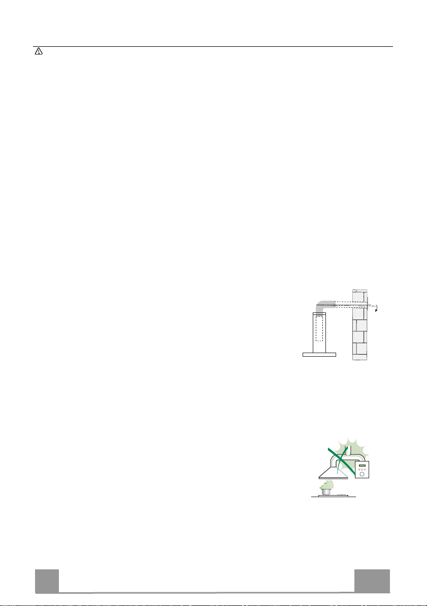
Connect the extractor to the exhaust flue through a pipe of minimum
diameter 120 mm. The route of the flue must be as short as possible.
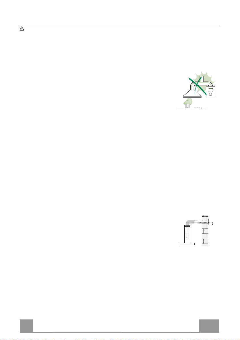
• Do not connect the extractor hood to exhaust ducts
carrying combustion fumes (boilers, fireplaces, etc.).
• If the extractor is used in conjunction with non-electrical
appliances (e.g. gas burning appliances), a sufficient
degree of aeration must be guaranteed in the room in
order to prevent the backflow of exhaust gas. The
kitchen must have an opening communicating directly
with the open air in order to guarantee the entry of clean air. When the
cooker hood is used in conjunction with appliances supplied with energy
other than electric, the negative pressure in the room must not exceed 0,04
mbar to prevent fumes being drawn back into the room by the cooker hood.
• The air must not be discharged into a flue that is used for
exhausting fumes from appliances burning gas or other
fuels (not applicable to appliances that only discharge the
air back into the room).
• In the event of damage to the power cable, it must be
replaced by the manufacturer or by the technical service
department, in order to prevent any risks.
2°
EN
3
3
Page 4

• If the instructions for installation for the gas hob specify a greater distance
specified above, this has to be taken into account. Regulations concerning
the discharge of air have to be fulfilled.
• Use only screws and small parts in support of the hood.
Warning: Failure to install the screws or fixing device in accordance with
these instructions may result in electrical hazards.
• Connect the hood to the mains through a two-pole switch having a contact
gap of at least 3 mm.
USE
• The extractor hood has been designed exclusively for domestic use to
eliminate kitchen smells.
• Never use the hood for purposes other than for which it has been designed.
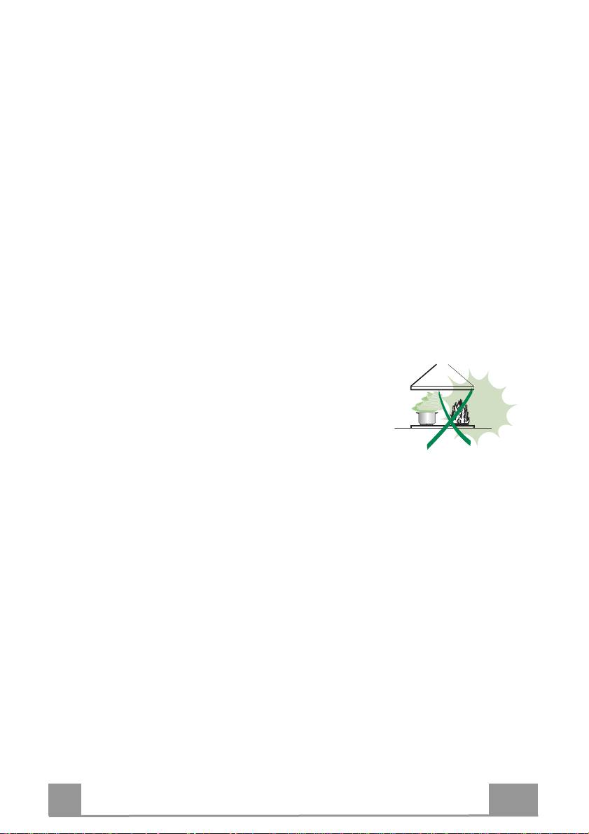
• Never leave high naked flames under the hood when it is in operation.
• Adjust the flame intensity to direct it onto the bottom of the pan only, making
sure that it does not engulf the sides.
• Deep fat fryers must be continuously monitored
during use: overheated oil can burst into flames.
• Do not flambè under the range hood; risk of fire.
• This appliance can be used by children aged from
8 years and above and persons with reduced
physical, sensory or mental capabilities or lack of
experience and knowledge if they have been given supervision or instruction
concerning use of the appliance in a safe way and understand the hazards
involved. Children shall not play with the appliance. Cleaning and user
maintenance shall not be made by children without supervision.
• This appliance is not intended for use by persons (including children) with
reduced physical, sensory or mental capabilities, or lack of experience and
knowledge, unless they have been given supervision or instruction
concerning use of the appliance by a person responsible for their safety.
EN
4
4
Page 5
• “CAUTION: Accessible parts may become hot when used with cooking
appliances.”
MAINTENANCE
• Switch off or unplug the appliance from the mains supply before carrying out
any maintenance work.
• Clean and/or replace the Filters after the specified time period (Fire hazard).
• The Grease filters must be cleaned every 2 months of operation, or more
frequently for particularly heavy usage, and can be washed in a dishwasher.
• The Activated charcoal filter is not washable and cannot be regenerated,
and must be replaced approximately every 4 months of operation, or more
frequently for particularly heavy usage.
• "Failure to carry out cleaning as indicated will result in a fire hazard".
• Clean the hood using a damp cloth and a neutral liquid detergent.
The symbol on the product or on its packaging indicates that this product
may not be treated as household waste. Instead it shall be handed over to the
applicable collection point for the recycling of electrical and electronic
equipment. By ensuring this product is disposed of correctly, you will help
prevent potential negative consequences for the environment and human
health, which could otherwise be caused by inappropriate waste handling of
this product. For more detailed information about recycling of this product,
please contact your local city office, your household waste disposal service or
the shop where you purchased the product.
EN
5
5
Page 6
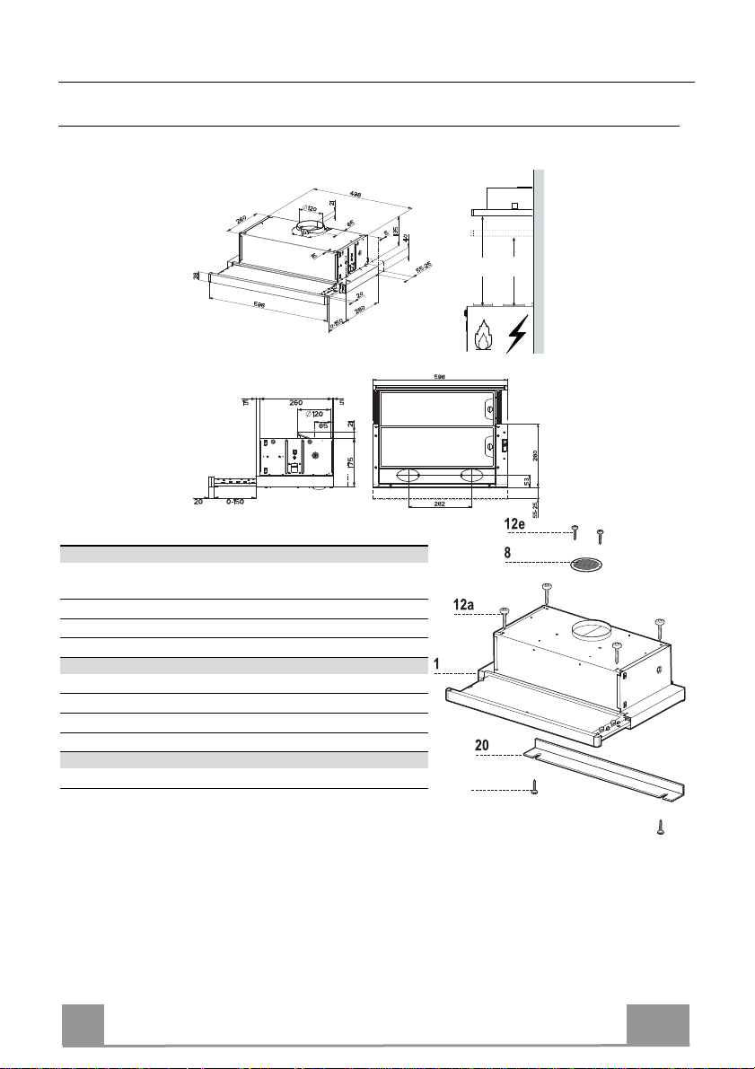
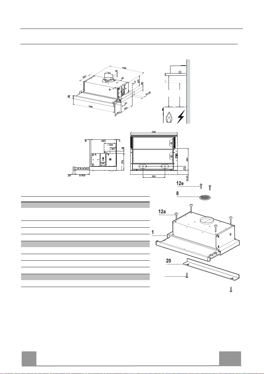
CHARACTERISTICS
Dimensions
Components
Ref. Q.ty Product Components
1 1 Hood Body, complete with: Controls, Light, Blower,
Filters
8 1 Directional Air Outlet grille
20 1 Closing element
Ref. Q.ty Installation Components
12a 4 Screws 4,2 x 44,4
12b 2 Screws 4,2 x 12,7
12e 2 Screws 2,9 x 12,7
Q.ty Documentation
1 Instruction Manual
Min.
650mm
12b
Min.
450mm
EN
6
6
Page 7

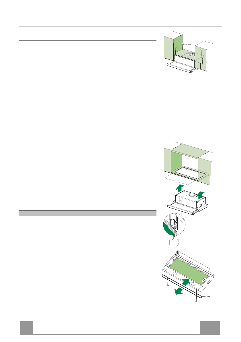
INSTALLATION
12a
135
125125
Drilling the Support surface and Fitting the Hood
SCREW FITTING
• The hood support surface must be 135 mm above the bottom
surface of the wall units.
• Drill the support with a ø 4,5 mm drill bit, using the drilling
template provided.
• Cut a hole ø 125 mm in size on the support surface, using the
drilling template provided.
• Fix using the 4 screws 12a (4,2 x 44,4) provided.
SNAP-ON FITTING
• The hood can be installed either directly on the bottom surface
of the wall units using snap-on side supports.
• Cut a fitted opening in the bottom surface of the wall unit, as
shown.
• Insert the hood until the side supports snap into place.
• Lock in position by tightening the screws Vf from underneath
the hood.
262
15
L1
Hood Type 45 50 55 60 70 80 90
L1 360 410 460 510 610 710 810
CLOSING ELEMENT
• The space between the edge of the hood and the rear wall can
be closed by applying the element 20 provided, using the
screws 12b.
EN
Vf
20
12b
7
7
Page 8
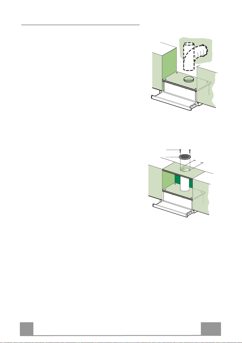
Connections
DUCTED VERSION AIR EXHAUST SYSTEM
When installing the ducted version, connect the hood to
the chimney using either a flexible or rigid pipe ø120
mm, the choice of which is left to the installer.
• Fix the pipe in position using sufficient pipe clamps
(not supplied).
• Remove any activated charcoal filters.
ø 120
RECIRCULATION VERSION AIR OUTLET
• Cut a hole ø 125 mm in any shelf that may be positioned over the hood.
• Connect the flange to the outlet on the shelf over the
hood using a flexible or rigid pipe ø120 mm.
• Fix the pipe in position using sufficient pipe clamps
(not supplied).
• Fix the directional grille 8 on the recirculation air
outlet using the 2 screws 12e (2,9 x 9,5) provided.
• Ensure that the activated charcoal filters have been
inserted.
12e
8
125125
9
ELECTRICAL CONNECTION
• Connect the hood to the mains through a two-pole switch having a contact gap of at least 3
mm.
• When opening the sliding carriage for the first time after installing the hood, pull it out
briskly until it clicks.
EN
8
8
Page 9
USE
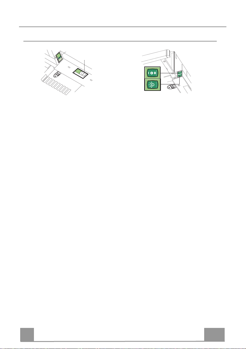
Control panel
L
0
1
M - V
0
1
2
3
M-V
L
L Light Switches the lighting system
on and off.
M Motor Switches the extractor motor
on and off.
V Speed Sets the operating speed of
the extractor:
1. Low speed, used for a
continuous and silent air
change in the presence of
light cooking vapour.
2. Medium speed, suitable
for most operating conditions given the optimum
treated air flow/noise
level ratio.
3. Maximum speed, used for
eliminating the highest
cooking vapour emission,
including long periods.
L Light Switches the lighting system
on and off.
M Motor Switches the extractor motor
on and off.
V Speed Sets the operating speed of
the extractor:
1. Low speed, used for a
continuous and silent air
change in the presence of
light cooking vapour.
2. Medium speed, suitable
for most operating conditions given the optimum
treated air flow/noise
level ratio.
EN
9
9
Page 10
MAINTENANCE
Grease filters
CLEANING METAL CASSETTE GREASE FILTERS
• The filters must be cleaned every 2 months, or more frequently
in case of particularly heavy use of the hood. Filters can be
washed in a dishwasher.
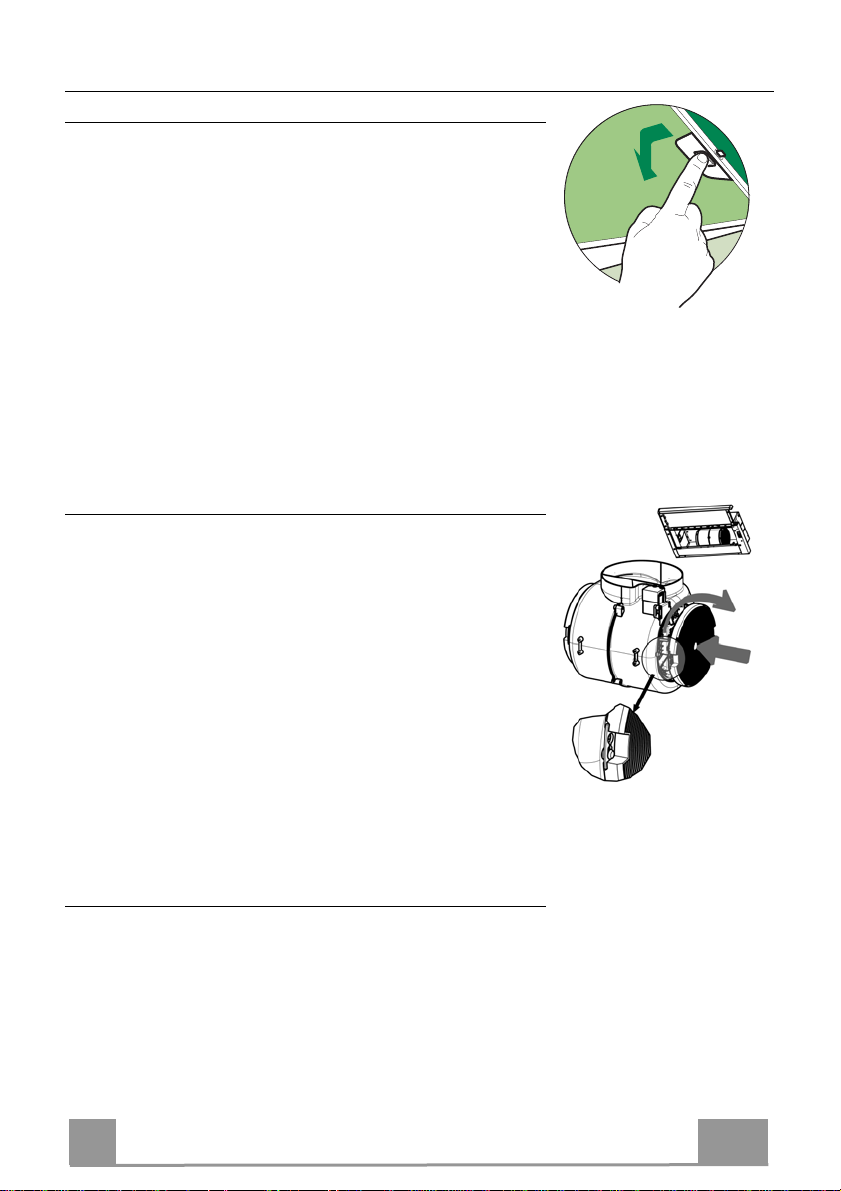
• Pull out the sliding suction panel.
• Remove the filters one by one, after having disconnected the
relative fastening elements.
• Wash the filters, taking care not to bend them. Let them get dry
before refitting them. (The colour of the filter surface may
change throughout the time but this has no influence to the filter efficiency).
• When refitting the filters, make sure that the handle is visible
on the outside.
• Close the sliding suction panel.
Charcoal filter (Recycling version)
REPLACING CHARCOAL FILTERS
Warning: Turn the lights off and wait until the lamps cool down
before you change the odour filter.
• These filters are not washable and cannot be regenerated, and
must be replaced approximately every four months or more
frequently by particularly heavy use.
• Pull out the sliding suction panel.
• Remove the grease filters.
• Remove the saturated carbon filter by releasing the fixing
hooks
• Fit the new filter by hooking it into its seating.
• Replace the grease filters.
• Close the sliding suction panel.
Lighting unit
• For replacement contact technical support ("To purchase
contact technical support").
EN
1
10
Page 11
CONSIGLI E SUGGERIMENTI
Le Istruzioni per l’uso si riferiscono ai diversi modelli di questo
apparecchio. Pertanto, si potrebbero trovare descrizioni di singole
caratteristiche che non appartengono al proprio apparecchio specifico.
INSTALLAZIONE
• Il fabbricante non potrà ritenersi responsabile per eventuali
danni risultanti da un’installazione o utilizzazione
impropria.
• La distanza minima di sicurezza tra il piano cottura e la
cappa aspirante è di 650 mm (alcuni modelli possono
essere installati a un’altezza inferiore; vedere il paragrafo
relativo alle dimensioni di lavoro e all'installazione).
• Controllare che la tensione di rete corrisponda a quella indicata sulla targa
dati applicata all’interno della cappa.
• Per gli apparecchi di Classe I, controllare che la rete di alimentazione
domestica disponga di un adeguato collegamento a massa.
Collegare l'aspiratore al condotto dei fumi mediante un tubo con diametro
minimo di 120 mm. Il percorso dei fumi deve essere il più corto possibile.
• Non collegare la cappa aspirante ai condotti fumari che trasportano fumi di
combustione (per es. caldaie, camini ecc.).
• Se l’aspiratore è utilizzato in combinazione con apparecchi non elettrici (per
es. apparecchi a gas), deve essere garantito un sufficiente grado di
aerazione nel locale per impedire il ritorno di flusso dei gas di scarico. La
cucina deve avere un'apertura comunicante direttamente
con l'esterno per garantire l'afflusso di aria pulita. Quando la
cappa per cucina è utilizzata in combinazione con
apparecchi non alimentati dalla corrente elettrica, la
pressione negativa nel locale non deve superare 0,04 mbar
per evitare che i fumi vengano riaspirati nel locale dalla cappa.
• L'aria non deve essere scaricata attraverso un tubo flessibile utilizzato per
l'aspirazione dei fumi da apparecchi alimentati a gas o altri combustibili (non
utilizzare con apparecchi che scaricano unicamente l'aria nel locale).
• In caso di danneggiamento del cavo di alimentazione, occorre farlo sostituire
dal produttore o dal reparto di assistenza tecnica per evitare qualsiasi
rischio.
2°
IT
11
1
Page 12
• Se le istruzioni di installazione del piano cottura a gas specificano una
distanza maggiore di quella sopra indicata, è necessario tenerne conto.
Devono essere rispettate tutte le normative riguardanti lo scarico dell'aria.
• Usare solo viti e minuteria di tipo idoneo per la cappa.
Avvertenza: la mancata installazione delle viti o dei dispositivi di fissaggio in
conformità alle presenti istruzioni può comportare rischi di scosse elettriche.
• Collegare la cappa all'alimentazione di rete mediante un interruttore bipolare
con distanza tra i contatti di almeno 3 mm.
USO
• La cappa aspirante è progettata esclusivamente per l’uso domestico allo
scopo di eliminare gli odori dalla cucina.
• Non usare mai la cappa per scopi diversi da quelli per cui è stata progettata.
• Non lasciare mai fiamme alte sotto la cappa quando è in funzione.
• Regolare l'intensità della fiamma in modo da dirigerla esclusivamente verso
il fondo del recipiente di cottura, assicurandosi che non ne avvolga i lati.
• Le friggitrici devono essere costantemente
controllate durante l’uso: l’olio surriscaldato
potrebbe incendiarsi.
• Non cuocere al flambé sotto la cappa: si potrebbe
sviluppare un incendio.
• Questo apparecchio può essere utilizzato da
bambini di età non inferiore a 8 anni e da persone con ridotte capacità psicofisico-sensoriali o con esperienza e conoscenze insufficienti, purché
attentamente sorvegliati e istruiti su come utilizzare in modo sicuro
l'apparecchio e sui pericoli che ciò comporta. Assicurarsi che i bambini non
giochino con l'apparecchio. Pulizia e manutenzione da parte dell'utente non
devono essere effettuate da bambini, a meno che non siano sorvegliati.
• Questo apparecchio non deve essere utilizzato da persone (bambini
compresi) con ridotte capacità psico-fisico-sensoriali o con esperienza e
conoscenze insufficienti, a meno che non siano attentamente sorvegliate e
istruite da una persona responsabile della loro incolumità.
IT
12
1
Page 13
• “ ATTENZIONE: le parti accessibili possono diventare molto calde durante
l’uso degli apparecchi di cottura ”.
MANUTENZIONE
• Spegnere o scollegare l’apparecchio dalla rete di alimentazione prima di
qualunque operazione di pulizia o manutenzione.
• Pulire e/o sostituire i filtri dopo il periodo di tempo specificato (pericolo di
incendio).
• I filtri antigrasso devono essere puliti ogni 2 mesi di funzionamento o più
frequentemente in caso di utilizzo molto intenso e possono essere lavati in
lavastoviglie.
• Il filtro al carbone attivo non è lavabile né è rigenerabile e deve essere
sostituito ogni 4 mesi di funzionamento circa o più frequentemente in caso di
utilizzo molto intenso.
• "Vi è il rischio di incendio se la pulizia non viene effettuata secondo le
istruzioni".
• Pulire la cappa utilizzando un panno umido e un detergente liquido neutro.
Il simbolo sul prodotto o sulla sua confezione indica che il prodotto non
può essere smaltito come un normale rifiuto domestico. Il prodotto da smaltire
deve essere conferito presso un apposito centro di raccolta per il riciclaggio
dei componenti elettrici ed elettronici. Assicurandosi che questo prodotto sia
smaltito correttamente, si contribuirà a prevenire potenziali conseguenze
negative per l’ambiente e per la salute che potrebbero altrimenti derivare dal
suo smaltimento inadeguato. Per informazioni più dettagliate sul riciclaggio di
questo prodotto, contattare il Comune, il servizio locale di smaltimento rifiuti
oppure il negozio dove è stato acquistato il prodotto.
IT
13
1
Page 14
CARATTERISTICHE
Ingombro
Componenti
Rif. Q.tà Componenti di Prodotto
1 1 Corpo Cappa completo di: Comandi, Luce, Gruppo
Ventilatore, Filtri
8 1 Griglia direzionata Uscita Aria
20 1 Profilo chiusura
Rif. Q.tà Componenti di Installazione
12a 4 Viti 4,2 x 44,4
12b 2 Viti 4,2 x 12,7
12e 2 Viti 2,9 x 12,7
Q.tà Documentazione
1 Libretto Istruzioni
Min.
650mm
12b
Min.
450mm
IT
14
1
Page 15
INSTALLAZIONE
12a
135
125125
Foratura Piano di supporto e Montaggio Cappa
MONTAGGIO CON VITI
• Il Piano di supporto della Cappa deve essere rientrante di 135
mm dal Piano inferiore dei Pensili.
• Forare ø 4,5 mm il supporto utilizzando la Dima di foratura in
dotazione.
• Praticare un foro ø 125 mm sul Piano di supporto, utilizzando
la Dima di foratura in dotazione.
• Fissare con 4 Viti 12a (4,2 x 44,4) in dotazione.
MONTAGGIO CON FISSAGGIO A SCATTO
• La Cappa può essere installata direttamente sul piano inferiore
dei Pensili con i Supporti laterali a scatto.
• Praticare un incasso sul piano inferiore del Pensile, come indicato.
• Inserire la Cappa fino ad agganciare i Supporti laterali a scatto.
• Bloccare definitivamente serrando le Viti Vf dal sotto della
Cappa.
262
15
L1
Tipo Cappa 45 50 55 60 70 80 90
L1 360 410 460 510 610 710 810
PROFILO DI CHIUSURA
• Lo spazio tra il bordo della Cappa e la Parete di fondo può essere chiuso applicando il Profilo 20 in dotazione con le Viti
12b.
IT
Vf
20
12b
1
15
Page 16

Connessioni
USCITA ARIA VERSIONE ASPIRANTE
Per installazione in Versione Aspirante collegare la
Cappa alla tubazione di uscita per mezzo di un tubo
rigido o flessibile di ø120 mm, la cui scelta è lasciata
all'installatore.
• Fissare il tubo con adeguate fascette stringitubo. Il
materiale occorrente non è in dotazione.
• Togliere eventuali Filtri Antiodore al Carbone attivo.
USCITA ARIA VERSIONE FILTRANTE
• Praticare un foro ø 125 mm sull’eventuale Mensola
soprastante la Cappa.
• Collegare la Flangia al foro di uscita sulla Mensola
soprastante la Cappa con un tubo rigido o flessibile di
ø120 mm.
• Fissare il tubo con adeguate fascette stringitubo. Il
materiale occorrente non è in dotazione.
• Fissare la Griglia direzionata 8 sull’uscita con 2 Viti
12e (2,9 x 9,5) in dotazione.
• Assicurarsi della presenza dei Filtri antiodore al Carbone attivo.
ø 120
12e
8
125125
9
CONNESSIONE ELETTRICA
• Collegare la Cappa all’Alimentazione di Rete interponendo un Interruttore bipolare con apertura dei contatti di almeno 3 mm.
• Dopo aver installato la cappa è necessario per la prima volta aprire il carrello scorrevole energicamente fino a sentire lo scatto di fine corsa.
IT
16
1
Page 17

USO
Quadro comandi
L
0
1
M - V
0
1
2
3
M-V
L
L Luci Accende e spegne l’Impianto
di Illuminazione.
M Motore Accende e spegne il motore
Aspirazione.
V Velocità Determina la velocità di e-
sercizio:
1. Velocità minima, adatta
ad un ricambio d’aria
continuo particolarmente
silenzioso, in presenza di
pochi vapori di cottura.
2. Velocità media, adatta
alla maggior parte delle
condizioni d’uso, dato
l’ottimo rapporto tra portata d’aria trattata e livello sonoro.
3. Velocità massima, adatta
a fronteggiare le massime
emissioni di vapore di
cottura, anche per tempi
prolungati.
L Luci Accende e spegne l’Impianto
di Illuminazione.
M Motore Accende e spegne il motore
Aspirazione.
V Velocità Determina la velocità di e-
sercizio:
1. Velocità minima, adatta
ad un ricambio d’aria
continuo particolarmente
silenzioso, in presenza di
pochi vapori di cottura.
2. Velocità media, adatta alla
maggior parte delle condizioni d’uso, dato
l’ottimo rapporto tra portata d’aria trattata e livello
sonoro.
IT
17
1
Page 18

MANUTENZIONE
Filtri antigrasso
PULIZIA FILTRI ANTIGRASSO METALLICI AUTOPORTANTI
• Sono lavabili anche in lavastoviglie, e necessitano di essere
lavati ogni 2 mesi circa di utilizzo o più frequentemente, per un
uso particolarmente intenso.
• Estrarre il carrello aspirante.
• Togliere i Filtri uno alla volta, agendo sugli appositi agganci.
• Lavare i Filtri evitando di piegarli, e lasciarli asciugare prima
di rimontarli. (Un’eventuale cambiamento del colore della superficie del filtro, che potrebbe verificarsi nel tempo, non pregiudica assolutamente l’efficienza dello stesso.)
• Rimontarli facendo attenzione a mantenere la maniglia verso la
parte visibile esterna.
• Chiudere il carrello aspirante.
Filtri antiodore (Versione Filtrante)
SOSTITUZIONE
Attenzione: Spegnere le luci ed attendere il raffreddamento delle
lampade prima di effettuare la sostituzione del filtro antiodore.
• Non sono lavabili né rigenerabili, vanno sostituiti ogni 4 mesi
circa di utilizzo o più frequentemente, per un uso particolarmente intenso.
• Estrarre il carrello aspirante.
• Togliere i Filtri Antigrasso
• Rimuovere il Filtro antiodore al Carbone attivo saturo, agendo
sugli appositi agganci.
• Rimontare i Filtri antigrasso.
• Richiudere il carrello aspirante.
Illuminazione
• Per la sostituzione contattare l’Assistenza Tecnica ("Per
l'acquisto rivolgersi all'assistenza tecnica").
IT
1
18
Page 19

CONSEILS ET SUGGESTIONS
Les instructions pour l’utilisation se réfèrent aux différents modèles de cet
appareil. Par conséquent, certaines descriptions de caractéristiques
particulières pourraient ne pas appartenir spécifiquement à cet appareil.
INSTALLATION
• En aucun cas le fabricant ne peut être tenu pour responsable d’éventuels
dommages dus à une installation ou à une utilisation impropre.
• La distance de sécurité minimum entre le plan de
cuisson et la hotte aspirante est de 650 mm (certains
modèles peuvent être installés à une hauteur inférieure ;
voir le paragraphe concernant les dimensions de travail
et l’installation).
• Assurez-vous que la tension de votre secteur correspond
à celle indiquée sur la plaque des données appliquée à
l’intérieur de la hotte.
• Pour les appareils de Classe I, s’assurer que l’installation électrique de votre
intérieur dispose d’une mise à la terre adéquate.
Relier l’aspirateur au conduit de cheminée avec un tube d’un diamètre minimum
de 120 mm. Le parcours des fumées doit être le plus court possible.
• Ne pas relier la hotte aspirante aux conduits de cheminée qui acheminent les
fumées de combustion (par exemple de chaudières, de cheminées, etc.).
• Si vous utilisez l’aspirateur en combinaison avec des
appareils non électriques (par ex. appareils à gaz), vous
devez garantir un degré d’aération suffisant dans la pièce,
afin d’empêcher le retour du flux des gaz de sortie. La
cuisine doit présenter une ouverture communiquant
directement vers l’extérieur pour garantir l’amenée d’air
propre. Si vous utilisez la hotte de cuisine en combinaison avec des appareils
non alimentés à l’électricité, la pression négative dans la pièce ne doit pas
dépasser 0,04 mbar afin d’éviter que la hotte ne réaspire les fumées dans la
pièce.
• Si le cordon d’alimentation est endommagé, veuillez le faire remplacer par le
fabricant ou par un service après-vente agréé pour éviter tout risque d’accident.
2°
FR
19
1
Page 20

• Si les instructions d’installation du plan de cuisson à gaz spécifient une
distance supérieure à celle indiquée ci-dessus, veuillez impérativement en
tenir compte. Toutes les normes concernant l’évacuation de l’air doivent être
respectées.
• Utiliser exclusivement des vis et des petites pièces du type adapté pour la
hotte.
Attention : toute installation des vis et des dispositifs de fixation non
conforme aux présentes instructions peut entraîner des risques de
décharges électriques.
• Brancher la hotte à l’alimentation de secteur avec un interrupteur bipolaire
ayant une ouverture des contacts d’au moins 3 mm.
UTILISATION
• Cette hotte aspirante a été conçue exclusivement pour un usage
domestique, dans le but d’éliminer les odeurs de cuisine.
• Ne jamais utiliser la hotte pour des objectifs différents de ceux pour lesquels
elle a été conçue.
• Ne jamais laisser un feu vif allumé sous la hotte lorsque celle-ci est en
fonction.
• Régler l’intensité du feu de manière à l’orienter exclusivement vers le fond
de la casserole, en vous assurant qu’il ne déborde pas sur les côtés.
• Contrôler constamment les friteuses durant leur
utilisation : l’huile surchauffée risque de s’incendier.
• Ne pas flamber des mets sous la hotte : sous risque
de provoquer un incendie.
• Cet appareil n’est pas destiné à être utilisé par des
enfants d’un âge inférieur à 8 ans, ni par des personnes dont les capacités
physiques, sensorielles ou mentales sont diminuées ou qui ont une
expérience et des connaissances insuffisantes, à moins que ces enfants ou
ces personnes ne soient attentivement surveillés et instruits sur la manière
d’utiliser cet appareil en sécurité et sur les dangers que cela comporte.
Assurez-vous que les enfants ne jouent pas avec cet appareil. Le nettoyage
et l’entretien de la part de l’utilisateur ne doivent pas être effectués par des
enfants, à moins que ce ne soit sous la surveillance d’une personne
responsable.
FR
20
2
Page 21

• ATTENTION : les parties accessibles peuvent devenir très chaudes durant
l’utilisation des appareils de cuisson.
ENTRETIEN
• Avant d’effectuer toute opération de nettoyage et d’entretien, éteindre ou
débrancher l’appareil du secteur.
• Nettoyer et/ou remplacer les filtres après le délai indiqué (danger
d’incendie).
• Nettoyer les filtres à graisse tous les 2 mois de fonctionnement ou plus
souvent en cas d’utilisation particulièrement intense. Ces filtres peuvent être
lavés au lave-vaisselle.
• Le filtre à charbon actif ne peut être ni lavé ni régénéré et il doit être
remplacé environ tous les 4 mois de fonctionnement ou plus souvent en cas
d’utilisation particulièrement intense.
• Effectuer le nettoyage selon les instructions, sous risque d'incendie.
• Nettoyer la hotte avec un chiffon humide et un détergent liquide neutre.
Le symbole marqué sur le produit ou sur son emballage indique que ce
produit ne peut pas être éliminé comme déchet ménager normal. Lorsque ce
produit doit être éliminé, veuillez le remettre à un centre de collecte prévu pour
le recyclage du matériel électrique et électronique. En vous assurant que cet
appareil est éliminé correctement, vous participez à prévenir des
conséquences potentiellement négatives pour l'environnement et pour la
santé, qui risqueraient de se présenter en cas d’élimination inappropriée. Pour
toute information supplémentaire sur le recyclage de ce produit, contactez
votre municipalité, votre déchetterie locale ou le magasin où vous avez acheté
ce produit.
FR
21
2
Page 22

CARACTERISTIQUES
Encombrement
Composants
Réf. Q.té Composants de Produit
1 1 Corps Hotte équipé de:Commandes, Lumière, Groupe
Ventilateur, Filtres
8 1 Grille orientée Sortie de l ’Air
20 1 Profil fermeture
Réf. Q.té Composants pour l ’installation
12a 4 Vis 4,2 x 44,4
12b 2 Vis 4,2 x 12,7
12e 2 Vis 2,9 x 12,7
Q.té Documentation
1 Manuel d’instructions
Min.
650mm
12b
Min.
450mm
FR
22
2
Page 23

INSTALLATION
12a
135
125125
Perçage du Plan de support et Montage de la Hotte
MONTAGE AU MOYEN DE VIS
• Le Plan de support de la Hotte doit être monté plus en haut de
135 mm. par rapport au Plan inférieur des Armoires murales.
• Percer un trou de ø 4,5 mm. sur le support, en utilisant le Gabarit de perçage fourni avec l’appareil.
• Percer un trou de ø 125 mm. sur le Plan de support, en utilisant
le Gabarit de perçage fourni avec l’appareil.
• Fixer à l’aide des 4 Vis 12a (4,2 x 44,4) fournies avec
l’appareil.
MONTAGE AVEC FIXATION PAR ENCLIQUETAGE
• Il est possible d’installer la Hotte directement sur le plan inférieur des Armoires murales au moyen de supports latéraux par
encliquetage.
• Effectuer un emboîtage sur le plan inférieur de l’Armoire murale, comme indiqué.
• Insérer la Hotte jusqu’à accrocher les Supports latéraux par
encliquetage.
• Bloquer définitivement en serrant les Vis Vf depuis le bas de la
Hotte.
Hotte Type 45 50 55 60 70 80 90
L1 360 410 460 510 610 710 810
262
15
L1
Vf
PROFIL DE FERMETURE
• Il est possible de boucher l’espace entre le rebord de la Hotte et
la Paroi du fond, en appliquant le Profil 20 fourni avec
l’appareil avec les Vis 12b.
FR
12b
20
23
2
Page 24

Branchements
SORTIE AIR VERSION EVACUATION
En cas d’installation en version évacuation, brancher la
hotte à la tuyauterie de sortie via un tube rigide ou
flexible de ø 120 mm, au choix de l’installateur.
• Fixer le tube par des colliers appropriés. Le matériau
nécessaire n’est pas fourni.
• Retirer les éventuels filtres anti-odeur au charbon
actif.
ø 120
SORTIE AIR VERSION RECYCLAGE
• Percer un trou de ø 125 mm. sur l’éventuelle Tablette
qui se trouve au-dessus de la Hotte.
• Connecter la Flasque au trou de sortie sur la Tablette
qui se trouve au-dessus de la Hotte, au moyen d’un
tuyau rigide ou flexible de ø120 mm.
• Fixer le tube par des colliers appropriés. Le matériau
nécessaire n’est pas fourni.
• Fixer la Grille orientée 8 sur la sortie de l’air recyclé
à l’aide de 2 Vis 12e (2,9 x 9,5) fournies avec
l’appareil.
• S’assurer de la présence des filtres anti-odeur au
charbon actif.
12e
8
125125
9
BRANCHEMENT ELECTRIQUE
• Brancher la hotte sur le secteur en interposant un interrupteur bipolaire avec ouverture des
contacts d’au moins 3 mm.
• Après avoir installé la hotte, il est indispensable pour la première fois d’ouvrir le chariot
coulissant de façon énergique, jusqu’à ce que l’on entende le déclic de fin de course.
FR
24
2
Page 25

UTILISATION
0
1
Tableau de commande
L
M - V
0
1
2
3
M-V
L
L Lumières Allume et éteint l’éclairage.
M Moteur Allume et éteint le moteur
aspiration.
V Vitesses Détermine les vitesses
d’exploitation ainsi subdivisées:
1. Vitesse minimale, pour
un rechange d’air permanent particulièrement silencieux en cas de faibles
vapeurs de cuisson.
2. Vitesse moyenne pour la
plupart des conditions
d’utilisation, étant donné
le rapport optimal entre
débit d’air traité et niveau
sonore.
3. Vitesse maximum, pour
faire face aux émissions
maximum de vapeur de
cuisson, même pendant
des temps prolongés.
L Lumières Allume et éteint l’éclairage.
M Moteur Allume et éteint le moteur
aspiration.
V Vitesses Détermine les vitesses
d’exploitation ainsi subdivisées:
1. Vitesse minimale, pour
un rechange d’air permanent particulièrement silencieux en cas de faibles
vapeurs de cuisson.
2. Vitesse moyenne pour la
plupart des conditions
d’utilisation, étant donné
le rapport optimal entre
débit d’air traité et niveau
sonore.
FR
25
2
Page 26

ENTRETIEN
Filtres anti-graisse
NETTOYAGE DES FILTRES ANTI-GRAISSE MÉTALLIQUES AUTOPOR-
TEURS
• Les filtres peuvent être également lavés au lave-vaisselle; il
faut les laver tous les 2 mois d’emploi environ, ou bien plus
souvent, en cas d’emploi particulièrement intense.
• Sortir le tiroir aspirant.
• Retirer un Filtre à la fois, en intervenant sur les crochets spécialement prévus.
• Laver les Filtres en évitant de les plier, puis laisser sécher
avant de les remonter(L’éventuel changement de couleur de la
surface du filtre, qui pourrait survenir au cours du temps, ne
porte absolument pas préjudice à l’efficacité de celui-ci.).
• Remonter les filtres, en faisant attention à ce que la poignée
soit orientée vers la partie visible externe.
• Fermer le tiroir aspirant.
Filtres anti-odeur (Version Recyclage)
REMPLACEMENT
Attention: Éteindre les lumières et attendre le refroidissement
des ampoules avant de procéder au remplacement du filtre antiodeur.
• Les filtres ne peuvent pas être lavés ni régénérés; il faut les
remplacer tous les 3-4 mois d’emploi environ ou bien plus
souvent, en cas d’emploi particulièrement intense.
• Sortir le chariot aspirant.
• Retirer les Filtres Anti-graisse.
• Retirer le Filtre anti-odeur au Charbon actif saturé, en intervenant sur les crochets spécialement prévus.
• Mettre le nouveau Filtre en l’accrochant bien en place.
• Remonter les Filtres anti-graisse.
• Refermer le chariot aspirant.
Éclairage
• Pour le remplacement, contacter le Service après-vente (« Pour
l’achat, s’adresser au service après-vente »).
FR
2
26
Page 27

EMPFEHLUNGEN UND HINWEISE
Diese Gebrauchsanleitungen beziehen sich auf die verschiedenen Modelle
der Abzugshaube. Darum kann es möglich sein, dass die Beschreibung
bestimmter Merkmale für das vorliegende Gerät nicht zutrifft.
INSTALLATION
• Der Hersteller haftet nicht für etwaige Schäden, die durch die fehlerhafte
Installation oder falschen Gebrauch entstehen könnten.
• Der min. Sicherheitsabstand zwischen Kochfeld
und Abzugshaube beträgt 650 mm (einige Modelle
können auch niedriger installiert werden; siehe
Absatz Installation).
• Kontrollieren Sie, ob die Netzspannung den Daten
des Typenschilds im Innern der Haube entspricht.
• Für Geräte der Klasse I muss kontrolliert werden,
ob das häusliche Versorgungsnetz korrekt geerdet
ist.
Die Absaughaube mit Hilfe eines Rohrs mit einem Mindestdurchmesser von
120 mm mit dem Rauchabzug verbinden. Der Verlauf des Rauchabzugs soll
so kurz wie möglich sein.
• Die Abzugshaube darf nicht an einen Schacht angeschlossen werden, in den
Rauchgase geleitet werden (z. B. von Heizkessel, Kaminen, usw.).
• Falls in dem Raum neben dem Abzug auch nicht
mit Strom betriebene Geräte (zum Beispiel
Gasgeräte) eingesetzt werden, muss für eine
ausreichende Belüftung gesorgt werden, damit der
Rückfluss der Abgase verhindert wird. Die Küche
muss eine direkte Öffnung nach Außen aufweisen,
damit ein ausreichender Luftaustausch
gewährleistet wird. Wird die Abzugshaube
zusammen mit nicht mit Strom betriebenen Geräte eingesetzt, darf der
Unterdruck im Raum 0,04 mbar nicht überschreiten, damit die Abgase nicht
wieder angesaugt werden.
• Schadhafte Kabel müssen durch den Hersteller oder vom Kundendienst
ausgewechselt werden, damit jedes Risiko ausgeschlossen wird.
2°
DE
27
2
Page 28

• Falls die Montageanweisungen für die gasbetriebene Kochmulde einen
größeren Abstand vorschreiben, als der oben angegebene, muss diese
Vorgabe befolgt werden. Es sind sämtliche Abluftvorschriften zu beachten.
• Nur für die Abzugshaube geeignete Schrauben und Kleinteile verwenden.
Achtung: Werden die Schrauben und Befestigungselemente nicht
entsprechend der vorliegenden Anleitungen verwendet, besteht
Stromschlaggefahr.
• Die Abzugshaube mittels zweipoligem Schalter mit einer Öffnung der
Kontakte von mindestens 3 mm an das Netz anschließen.
GEBRAUCH
• Die Abzugshaube wurde ausschließlich für den häuslichen Gebrauch
entwickelt, um Kochdünste zu beseitigen.
• Die Haube darf nur für die ihr zugedachten Zwecke benutzt werden.
Achtung! Große Flammen bei eingeschalteter Haube niemals
unbedeckt lassen.
• Die Flamme so regulieren, dass sie nicht über den Boden des Kochgeschirrs
hinausreicht.
Achtung! Frittiergeräte müssen während des Gebrauchs stets
beaufsichtigt werden: Überhitztes Öl kann sich entzünden.
• Auf keinen Fall unter der Haube flambieren: Brandgefahr.
• Kinder ab 8 Jahren und Personen mit
eingeschränkten physischen, sensorischen oder
psychischen Fähigkeiten, oder mit mangelnden
Erfahrungen oder Kenntnissen dürfen nicht mit
dem Gerät umgehen, es sei denn, sie werden von
einer für ihre Sicherheit verantwortlichen Person
beaufsichtigt oder angeleitet. Sicherstellen, dass Kinder nicht mit dem Gerät
herumspielen können. Reinigungs- und Wartungsarbeiten dürfen nicht von
unbeaufsichtigten Kindern durchgeführt werden.
DE
28
2
Page 29

• ACHTUNG: Die zugänglichen Teile können während des Gebrauchs der
Kochgeräte sehr heiß werden.
WARTUNG
• Vor Reinigungs- oder Wartungsarbeiten am Gerät, muss dieses
ausgeschaltet und spannungslos gemacht werden.
• Die Filter stets nach den angegebenen Intervallen reinigen oder
auswechseln (Brandgefahr).
• Die Fettfilter sind alle 2 Monate oder bei intensiver Nutzung öfter zu reinigen
und können in der Spülmaschine gespült werden.
• Der Aktivkohlefilter ist weder waschbar, noch regenerierbar und muss bei
normalem Betrieb zirka alle 4 Monate oder auch öfter ausgewechselt
werden, je nach Intensität des Gebrauchs.
• „Wenn die Reinigung nicht nach den Anweisungen durchgeführt wird,
besteht Brandgefahr“.
• Die Haube mit einem feuchten Lappen und einem neutralen
Reinigungsmittel abwischen.
Das Symbol am Produkt oder auf der Verpackung weist darauf hin, dass
das Gerät nicht als normaler Hausmüll entsorgt werden darf. Das ausrangierte
Gerät muss vielmehr bei einer speziellen Sammelstelle für elektrische und
elektronische Geräte abgegeben werden. Mit der vorschriftsmäßigen
Entsorgung des Gerätes trägt der Benutzer dazu bei, schädliche
Auswirkungen auf Umwelt und Gesundheit zu vermeiden. Weitere
Informationen zum Recycling dieses Produktes können bei der zuständigen
Behörde, der örtlichen Abfallbeseitigung oder bei dem Händler, der das Gerät
verkauft hat, eingeholt werden.
DE
29
2
Page 30

CHARAKTERISTIKEN
Platzbedarf
Komponenten
Pos. St. Produktkomponenten
1 1 Haubenkörper mit Schaltern, Beleuchtung, Gebläse-
gruppe, Filter
8 1 Luftleitgitter Luftaustritt
20 1 Abdeckprofil
Pos. St. Montagekomponenten
12a 4 Schrauben 4,2 x 44,4
12b 2 Schrauben 4,2 x 12,7
12e 2 Schrauben 2,9 x 12,7
St. Dokumentation
1 Bedienungsanleitung
Min.
650mm
12b
Min.
450mm
DE
30
3
Page 31

MONTAGE
12a
135
125125
Bohren der Trägerplatte und Montage der Dunstabzugshaube
MONTAGE MIT SCHRAUBEN
• Die Hauben-Trägerplatte muss 135 mm oberhalb der Oberschrank-Unterfläche positioniert werden.
• Mit Hilfe des beiliegenden Bohrplanes Löcher ø 4,5 mm in die
Trägerplatte bohren.
• Mit Hilfe des beiliegenden Bohrplanes ein Loch ø 125 mm in
die Trägerplatte bohren.
• Mit 4 der mitgelieferten Schrauben 12a (4,2 x 44,4) fixieren.
MONTAGE MIT SCHNAPPVERSCHLUSS
• Die Haube kann direkt an der Oberschrank-Unterfläche mit
seitlichen Einrasthalterungen montiert werden.
• Die Einbauvorrichtung laut Abbildung an der Unterseite des
Oberschrankes anbringen.
• Die Haube einführen, bis die seitlichen Schnappverschlüsse
einrasten.
• Mit Hilfe der Schrauben Vf die Haube von der Unterseite her
definitiv fixieren.
262
15
L1
Hauben-typ 45 50 55 60 70 80 90
L1 360 410 460 510 610 710 810
ABDECKPROFIL
• Der Bereich zwischen Haubenkante und Rückwand kann mit
Hilfe des mitgelieferten Abdeckprofils 20 und der für diesen
Zweck vorgesehenen Schrauben geschlossen werden 12b.
DE
Vf
20
12b
3
31
Page 32

Anschlüsse
ANSCHLUSS IN ABLUFTVERSION
Bei Abluftbetrieb kann die Haube vom Installateur
wahlweise mittels Rohr oder Schlauch (ø120 mm) an
die Außenrohrleitung angeschlossen werden.
• Das Rohr mit geeigneten Rohrschellen fixieren. Das
hierzu erforderliche Material wird nicht mitgeliefert.
• Eventuell vorhandene Aktivkohlefilter entnehmen.
ø 120
ANSCHLUSS IN UMLUFTVERSION
• In das eventuell über der Haube vorhandene Bord ein
Loch ø 125 mm bohren.
• Den Flansch beim Luftaustritt am Bord oberhalb der
Haube mittels Rohr oder Schlauch ø120 mm anschließen.
• Das Rohr mit geeigneten Rohrschellen fixieren. Das
hierzu erforderliche Material wird nicht mitgeliefert.
• Das Luftleitgitter 8 mit Hilfe von 2 der mitgelieferten
Schrauben 12e (2,9 x 9,5) beim Austritt der rückzuführenden Luft fixieren.
• Sicherstellen, dass der Aktivkohle-Geruchsfilter vorhanden ist.
12e
8
125125
9
ELEKTROANSCHLUSS
• Bei Anschluss der Haube an das Stromnetz muss ein zweipoliger Schalter mit einem Öffnungsweg von mindestens 3 mm zwischengeschaltet werden.
• Nach Montage der Haube muss beim ersten Mal der Auszug energisch geöffnet werden, bis
bei Erreichen des Endanschlages ein Klicken zu hören ist.
Achtung! Alle Querschnittänderungen oder Richtungsänderungen des Abluftkanals reduzie-
ren die Leistung der Haube.
DE
32
3
Page 33

BEDIENUNG
0
1
Bedienfeld
L
M - V
0
1
2
3
M-V
L
L Beleucht. Schaltet die Beleuchtung ein
und aus.
M Motor Schaltet den Gebläsemotor
ein und aus.
V Geschw. bestimmt die Gebläsegech-
windigkeit und steuert folgende Geschwindigkeitsstufen:
1. geringste Gebläsestufe,
diese Stufe ist für einen
ständigen und besonders
leisen Luftaustausch bei
geringer Kochdunstentwicklung geeignet.
2. mittlere Gebläsestufe,
eignet sich aufgrund des
guten Verhältnisses zwischen Fördervolumen und
Geräuschentwicklung für
die meisten Anwendungssituationen.
3. höchste Gebläsestufe,
eignet sich für starke
Kochdunstentwicklung,
auch über längere zeithin.
L Beleucht. Schaltet die Beleuchtung ein
und aus.
M Motor Schaltet den Gebläsemotor
ein und aus.
V Geschw. bestimmt die Gebläsegech-
windigkeit und steuert folgende Geschwindigkeitsstufen:
1. geringste Gebläsestufe,
diese Stufe ist für einen
ständigen und besonders
leisen Luftaustausch bei
geringer Kochdunstentwicklung geeignet.
2. mittlere Gebläsestufe,
eignet sich aufgrund des
guten Verhältnisses zwischen Fördervolumen und
Geräuschentwicklung für
die meisten Anwendungssituationen.
DE
33
3
Page 34

WARTUNG
Fettfilter
• Die Filter können im Geschirrspüler gereinigt werden und
müssen nach spätestens zwei Monaten Betriebszeit oder, bei
besonders intensiver Nutzung, häufiger gereinigt werden.
• Den Wrasenleitschirm herausziehen.
• Die Verriegelung des Fettfilters zuerst nach hinten, dann nach
unten herausnehmen.
• Die Filter im Geschirrspüler bei stärkstem Reinigungsprogramm und höchster Temperatur, mindestens 65°C, reinigen
und vor dem Wiedereinsetzen trocknen lassen, dabei nicht knicken. (Eine eventuelle Verfärbung der Filteroberfläche, zu der
es im Laufe der Zeit kommen kann, beeinträchtigt die Funktion
des Filters keinesfalls.)
• Die Filter wieder einsetzen, dabei darauf achten, dass die Verriegelung sichtbar ist.
• Den Wrasenleitschirm wieder einschieben.
Achtung: Die Beleuchtung ausschalten und warten, bis die Lampe abgekühlt ist, bevor der Geruchsfilter ausgewechselt wird.
• Die Filter lassen sich nicht reinigen oder regenerieren und
müssen spätestens nach vier Monaten Betriebszeit oder, bei besonders intensiver Nutzung, häufiger ersetzt werden.
• Den Wrasenleitschirm herausziehen.
• Die Fettfilter entnehmen
• Die entsprechenden Haken lösen und den gesättigten Aktivkohlefilter entnehmen.
• Die Metallfettfilter wieder montieren.
• Die Fettfilter wieder einsetzen.
• Den Wrasenleitschirm wieder einschieben.
REINIGUNG DER METALLFETTFILTER
Aktivkohlefilter (Umluftbetrieb)
FILTERWECHSEL
Beleuchtung
LED-Strahler
• Für den Austausch der LED-Strahler wenden Sie sich bitte an den
Kundendienst.
DE
3
34
Page 35

TAVSİYELER VE ÖNERİLER
Kullanım talimatları, bu ev aletinin çeşitli modelleri için geçerlidir. Aynı
şekilde, bu ürünle ilgisi olmayan özelliklerin tanımlarını da görebilirsiniz.
MONTAJ
• Yanlış veya hatalı montajdan doğan yaralanma ve hasarlar için imalatçı
yükümlü olmayacaktır.
• Pişiricinin üst kısmı ve davlumbaz arasındaki
minimum güvenlik mesafesi 650 mm'dir. (Bazı
modeller daha alçak mesafeye monte edilebilir,
lütfen çalışma boyutları ve montaj paragraflarına
bakınız.)
• Ana voltajın davlumbazın iç tarafına sabitlenmiş
olan derecelendirme plakasındaki ile uyumlu
olduğunu kontrol edin.
• I. sınıf ev aletleri için, ev güç kaynağının yeterli
topraklama sağladığından emin olun.
Aspiratörü egzoz bacasına minimum çapı 120 mm olan bir boru vasıtasıyla
bağlayın. Baca hattı mümkün olduğu kadar kısa olmalıdır.
• Davlumbazı tutuşabilir gazlar taşıyan egzoz kanallarına bağlamayın
(kazanlar, şömineler, vs.).
• Eğer davlumbaz elektrikli olmayan ev aletleri ile
birlikte kullanılacaksa (ör. gazlı ev aletleri), egzoz
gazının geri tepmesini engellemek adına odada
yeterli derecede bir havalandırma olması garanti
edilmelidir. Temiz havanın girişini garanti etmek
adına mutfakta temiz hava girişini sağlayan bir
açıklık olmalıdır. Davlumbazın elektrik dışında
enerji veren ev aletleri ile birlikte kullanılması
durumunda, davlumbazın gazları geri yollamasını engellemek adına odadaki
negatif basınç 0,04 barı aşmamalıdır.
• Güç kablosuna zarar gelmesi durumunda, herhangi bir riski engellemek
adına imalatçı veya teknik servis birimince değiştirilmelidir.
2°
TR
35
3
Page 36

• Gaz ocağının montaj talimatlarında yukarıda belirtilenden daha fazla bir
mesafe belirtilmişse, buna dikkat edilmesi gerekir. Hava deşarjı ile ilgili
yönetmeliklere uyulması gerekir.
• Davlumbazı desteklemek için sadece vida ve küçük parçalar kullanın.
Uyarı: İşbu talimatlar uyarınca vidaları veya sabitleme aletlerini
kullanmamak elektrik tehlikelerine yol açabilir.
• Davlumbazı, arasında en az 3mm irtibat mesafesi olan iki kutuplu bir anahtar
vasıtasıyla cereyana bağlayın.
KULLANIM
• Davlumbaz mutfak kokularını gidermek adına ev kullanımı için
tasarlanmıştır.
• Davlumbazı asla tasarlandığı amaçlar haricinde kullanmayın.
• Davlumbaz çalışırken altında boşuna yanan yüksek ateş asla bırakmayın.
• Ateş yoğunluğunu sadece tencere altında kalacak ve yanlardan
taşmadığından emin olacak şekilde ayarlayın.
• Fritözler kullanım esnasında sürekli izlenmelidir:
fazla ısınmış yağ, ateş alabilir.
• Davlumbaz altında flambe yapmayınız; yangın
riski.
• Bu ev aleti, 8 yaş üstü çocuklar ve fiziksel,
duyusal veya akli yetersizliği olan veya tecrübe ve
bilgi eksikliği olan kişilerce bu kişilerin güvenliğinden sorumlu olan kişilerin
gözetimi altında veya ev aletinin kullanımı ile ilgili talimatlar kendilerine
verildiği durumlarda kullanılabilir. Çocuklar, ev aleti ile oynamamalıdır.
Temizleme ve bakım gözetimde olmadıklarında çocuklarca yapılmayacaktır.
TR
36
3
Page 37

• “ DİKKAT: Pişirme aletleri ile kullanıldıklarında temas edilebilir parçalar
ısınabilir.”
BAKIM
• Herhangi bir bakım işlemine başlamadan evvel ev aletini kapatın veya ana
güç kaynağından fişini çekin.
• Belirlenmiş zaman sonunda filtreleri temizleyin ve/veya değiştirin (Yangın
tehlikesi).
• Yağ filtreleri her 2 ayda bir veya yoğun kullanım olması durumunda daha sık
olarak temizlenmelidir ve bulaşık makinesinde yıkanabilirler.
• Aktif karbon filtresi yıkanabilir değildir, yeniden kullanılamaz ve her 4 ayda
bir veya yoğun kullanım olması durumunda daha sık olarak değiştirilmelidir.
• "Temizliğin talimatlara uygun olarak yapılmadığı durumlarda yangın riski
vardır."
• Davlumbazı nemli bir bez ve nötr sıvı deterjanla temizleyin.
Ürün üstündeki veya paketindeki sembolü, bu ürünün evsel atık olarak
değerlendirilmeyeceğinin göstergesidir. Elektrikli ve elektronik ekipmanın geri
dönüşümü için uygun toplama noktasına teslim edilmelidir. Bu ürünün doğru
şekilde bertaraf edildiğinden emin olarak, bu atık ürününün uygun olmayan
şekilde işlenmesinden doğacak çevre ve insan sağlığı için potansiyel olumsuz
sonuçların engellenmesine yardımcı olacaksınız. Bu ürünün geri dönüşümü ile
ilgili daha detaylı bilgi için lütfen yerel yetkili ofisiniz, evsel atık bertaraf hizmeti
veya ürünü satın aldığınız mağaza ile irtibata geçiniz.
TR
37
3
Page 38

ÖZELLIKLER
Boyutlar
Parçalar
Ref. Adedi Ürünün
1 1 Davlumbaz gövdesi ile: Kontrol düğmeleri. Lamba,
Üfleyici, Filtreler
8 1 Yönlendirmeli Hava Çıkış Izgarası
20 1 Kapatma elemanı
Ref. Adedi Montaj Parçaları
12a 4 Vidalar 4,2 x 44,4
12b 2 Vidalar 4,2 x 12,7
12e 2 Vidalar 2,9 x 12,7
Adedi malzeme
1 Kullanim Kilavuzu
Min.
650mm
12b
Min.
450mm
TR
38
3
Page 39

MONTAJ
12a
135
125125
Destek yüzeyinin delinmesi ve davlumbaz montajı
VİDALAR İLE MONTAJ
• Davlumbazın destek yüzeyi, desteklerin alt yüzünden 135 mm
içeride olması gerekmektedir.
• Verilen kalıbı kullanmak sureti ile destekte ø 4,5 mm çapında
bir delik açın.
• Verilen kalıbı kullanmak sureti ile destek yüzeyinde ø 125 mm
çapında bir delik açın.
• Verilen 4 adet 12a (4,2 x 44,4) vida ile tespit edin.
GEÇMELİ TESPİT DÜZENEĞİ İLE MONTAJ
• Davlumbaz, geçmeli yan destekler vasıtası ile doğrudan
desteklerin alt katına monte edilebilir .
• Desteklerin alt katına, belirtilen şekilde bir delik açın.
• Geçmeli yan destekleri takana kadar davlumbazı yerleştirin.
• Vf vidalarını alttan sıkıştırarak davlumbazı bloke edin.
262
15
L1
Davlumbaz 45 50 55 60 70 80 90
L1 360 410 460 510 610 710 810
KAPATMA PROFİLİ
• Davlumbazın kenarı ile arka Duvarın arasındaki boşluk, bu
amaç için verilen vidalar ile 20 profili uygulanmak sureti ile
kapatılabilir 12b.
TR
Vf
20
12b
3
39
Page 40

Bağlantılar
ASPİRATÖRLÜ MODEL HAVA ÇIKIŞI
Aspiratörlü modelin montajı için, davlumbaz, montörün
seçeceği 120 mm çapında sert veya esnek bir boru ile
çıkış kanalına bağlanmalıdır.
• Boruyu uygun kelepçelerle sıkarak sabitleyiniz. Bu
malzeme davlumbaz donanımıyla birlikte verilmemiştir.
• Varsa aktif karbonlu koku alma filtrelerini çıkarınız.
ø 120
FİLTRELİ MODEL HAVA ÇIKIŞI
• Davlumbazın üzerinde eğer mevcut ise yerleşik bulunan ø 125 mm çapında bir delik açınız.
• Davlumbaz üzerindeki konsoldaki çıkış deliğine
flanşı 120 mm çapında esnek ya da sert bir boru ile
bağlayınız.
• Boruyu uygun özellikte kelepçelerle sıkınız. Gereken
malzeme cihaz donanımıyla birlikte verilmemiştir.
• Yönlendirmeli ızgarayı 8 donanımdaki 2 adet vida ile
12e (2,9 x 9,5) çıkış noktasına sabitleyiniz.
• Aktif karbonlu koku filtrelerinin mevcut oldukların-
dan emin olunuz.
12e
8
125125
9
ELEKTRİK BAĞLANTISI
• Davlumbazı, en az 3 mm kontak açıklığı olan çift kutuplu bir anahtar üzerinde şebeke cereyanına bağlayın.
• Davlumbaz ilk kez monte edildikten sonra, yürüyen arabanın, tamponda klik sesi duyulana
kadar el ile açılması gerekmektedir.
TR
40
4
Page 41

KULLANIM
Kumanda tablosu
L
0
1
M - V
0
1
2
3
M-V
L
L Işıklar Aydınlatma tesisatını açıp
kapatır.
M Motor Hava çekme motorunu açıp
kapatır.
V Hız Çalışma hızını belirler:
1. Az miktarda pişirme bu-
harı olduğunda, sürekli ve
özellikle sessiz bir hava
devir daimine uygun minimum hız.
2. Hava emme gücü ve ses
seviyesi arasındaki
optimal orantı sayesinde
kullanım şartlarının bü-
yük bir kısmına uygun orta seviyede hız.
3. Uzun sürelerde de maksimum pişirme buharı
emisyonlarını göğüslemeye uygun maksimum
hız.
L Işıklar Aydınlatma tesisat
ını açıp
kapatır.
M Motor Hava çekme motorunu açıp
kapatır.
V Hız Çalışma hızını belirler:
1. Az miktarda pişirme bu-
harı olduğunda, sürekli ve
özellikle sessiz bir hava
devir daimine uygun minimum hız.
2. Hava emme gücü ve ses
seviyesi arasındaki
optimal orantı sayesinde
kullanım şartlarının bü-
yük bir kısmına uygun orta seviyede hız.
TR
41
4
Page 42

BAKIM
Yağ filtreleri
MONTELİ METAL YAĞ FİLTRELERİNİN TEMİZLİĞİ
• Bulaşık makinesinde yıkanabilirler, 2 ayda bir veya özellikle
yoğun kullanım söz konusu ise daha sık yıkanmalıdırlar.
• Emme arabasını çıkartın.
• Kancalarına bastırmak sureti ile filtreleri teker teker çıkartın.
• Filtreleri katlamadan yıkayın ve monte etmeden önce kurutun.
(Zamanla filtre yüzeyinde meydana gelebilecek renk değişikli-
ği filtrenin etkinliğinde kesinlikle bir azalmaya neden olmaz.)
• Kolu dışarıdan görülen tarafta kalacak şekilde yeniden monte
edin.
• Emme arabasını kapatın.
Koku filtreleri (Filtreli Versiyon)
DEĞİŞTİRME
Dikkat: Koku filtresini değiştirmeden önce ışıkları kapayın ve
lambaların soğumasını bekleyin.
• Yıkanmazlar ve yeniden kullanılamazlar, yaklaşık her 4 ay kullanıldıktan sonra veya özellikle yoğun kullanım söz konusu ise
değiştirilirler.
• Emme arabasını çıkartın.
• Yağ filtrelerini çıkartın.
• Kancalarından bastırarak koku filtresini aktif satüre karbondan
çıkartın.
• Yeni filtreyi yuvasına takınız.
• Yağ filtresini yerine takın.
• Emme arabasını kapatın.
Aydınlatma
• Değiştirmek için Teknik Servisle bağlantı kurun ("Edinmek
için teknik servisle bağlantı kurun").
TR
4
42
Page 43

RADY A DOPORUČENÍ
Tento Návod k použití se týká různých modelů tohoto přístroje. Z tohoto
důvodu je možné, že se setkáte s popisem různých charakteristik, které se
netýkají Vašeho přístroje.
INSTALACE
• Výrobce není odpovědný za případné škody způsobené nesprávně provedenou
instalací či nesprávným používáním přístroje.a.
• Minimální bezpečnostní vzdálenost mezi varnou
plochou a odsávací digestoří je 650 mm (některé
modely mohou být nainstalovány do nižší výšky;
viz odstavec týkající se provozních rozměrů a
instalace).
• Zkontrolujte, zda síťové napětí odpovídá
hodnotám uvedeným na štítku uvnitř digestoře.
• U přístrojů Třídy I zkontrolujte, zda je síť
domácího napájení vhodně uzemněna.
Připojte odsávač k dýmníku pomocí trubice o minimálním průměru 120 mm.
Trasa výparů musí být co nejkratší.
• Nepřipojujte odsávací digestoř ke komínům, které odvádějí zplodiny ze
spalování (např. kotle, komíny apod.).
• Pokud je odsávač používán v kombinaci s
neelektrickými přístroji (např. plynovými), musí
být v místnosti zaručeno dostatečné větrání, aby
nemohlo dojít k návratu plynových zplodin.
Kuchyň musí být vybavena otvorem, který je
přímo propojen s vnějším prostorem, aby bylo
zaručeno proudění čistého vzduchu. Jestliže je
kuchyňská digestoř používána v kombinaci s přístroji, které nejsou napájeny
elektrickým proudem, záporný tlak v místnosti nesmí být vyšší než 0,04
mbar, aby nemohlo dojít ke zpětnému nasávání výparů do místnosti, kde se
nachází digestoř.
• Výměnu napájecího kabelu v případě jeho poškození musí provést výrobce
nebo oddělení technického servisu, aby bylo vyloučeno jakékoliv riziko.
2°
CZ
43
4
Page 44

• Jestliže je v návodu k instalaci plynového sporáku uvedena větší vzdálenost
než výše uvedená, je třeba to vzít v úvahu. Musí být dodrženy všechny
normy týkající se odvodu vzduchu.
• Použijte pouze šrouby a spojovací materiál vhodného typu pro digestoř.
Upozornění: nebude-li provedena instalace šroubů nebo upevňovacích
zařízení podle tohoto návodu, mohlo by vzniknout nebezpečí zasažení
elektrickým proudem.
• Připojte digestoř k napájecí síti za použití dvoupólového vypínače s nejméně
3 mm vzdáleností mezi kontakty.
POUŽITÍ
• Odsávací digestoř je projektována výlučně pro domácí použití, k
odstraňování pachů z kuchyně.
• Nikdy nepoužívejte digestoř k jiným účelům než k těm, pro které je určena.
• Nikdy nenechávejte pod digestoří při chodu vysoký plamen.
• Seřiďte intenzitu plamene tak, aby byl nasměrován pouze na dno varné
nádoby a ujistěte se, aby nešlehal po jejích stranách.
• Kontrolujte fritovací hrnce během používání: příliš
zahřátý olej by se mohl vznítit.
• Pod kuchyňskou digestoří nepřipravujte
flambované pokrmy, je zde nebezpečí požáru.
• Tento spotřebič může být používán dětmi ve věku
nad 8 let a osobami se sníženými fyzickými,
smyslovými nebo duševními schopnostmi nebo bez patřičných zkušeností a
znalostí, pokud jsou pod pečlivým dohledem nebo byly seznámeny s pokyny
k použití přístroje bezpečným způsobem a rozumí jeho rizikům. Zkontrolujte,
zda si děti nehrají s přístrojem. Čištění a údržba, které mají být vykonávány
uživatelem, nesmí být prováděny dětmi, pokud nejsou pod dozorem.
CZ
44
4
Page 45

• “ POZOR: přístupné části mohou při používání varných přístrojů dosahovat
vysokých teplot „.
ÚDRŽBA
• Před čištěním či jakoukoliv operací údržby přístroj vypněte nebo jej odpojte
od napájecí sítě.
• Vyčistěte a/nebo vyměňte filtry po uvedené době (nebezpečí vznícení).
• Tukové filtry je třeba čistit po každých 2 měsících používání nebo i častěji v
případě intenzívního používání, je možné je mýt v myčce.
• Uhlíkový filtr nelze mýt ani regenerovat, ale je třeba ho vyměnit zhruba po
každých 4 měsících používání nebo v případě potřeby i častěji.
• "Jestliže čištění není prováděno podle návodu, je zde riziko vznícení".
• Digestoř čistěte navlhčeným hadrem a neutrálním tekutým čisticím
prostředkem.
Symbol na výrobku nebo na jeho obalu označuje, že výrobek nemůže být
zlikvidován jako normální domácí odpad. Výrobek, který má být likvidován,
musí být odevzdán do specializovaných sběren pro recyklaci elektrických a
elektronických komponentů. Tím, že se ujistíte o řádném provedení likvidace
tohoto výrobku, přispějete k zabránění případného negativního dopadu na
životní prostředí a na zdraví osob, který by mohla mít nesprávně provedená
likvidace. Podrobnější informace o recyklaci tohoto výrobku získáte na
obecním úřadě, v místním podniku pro sběr domácího odpadu nebo v
obchodě, kde jste spotřebič zakoupili.
CZ
45
4
Page 46

HLAVNÍ PARAMETRY
Prostorový rozměr
Díly
Č. Poč. Díly spotřebiče
1 1 Těleso digestoře s: ovládáním, osvětlením, jednotkou
ventilátoru, filtry
8 1 Směrovatelná mřížka s výstupem vzduchu
20 1 Uzavírací profil
Č. Poč. Díly k instalaci
12a 4 Šrouby 4,2 x 44,4
12b 2 Šrouby 4,2 x 12,7
12e 2 Šrouby 2,9 x 12,7
Poč. Dokumentace
1 Návod k použití
Min.
650mm
12b
Min.
450mm
CZ
46
4
Page 47

INSTALACE
12a
135
125125
Vyvrtání podpůrné desky a montáž digestoře
MONTÁŽ SE ŠROUBY
• Podpůrná deska digestoře musí ustupovat o 135 mm vzhledem
k dolní ploše závěsných skříněk.
• Vyvrtejte ř 4,5 mm do podpůrné desky s pomocí vrtací šablo-
ny, která je součástí vybavení.
• Vyvrtejte otvor ř 125,5 mm do podpůrné desky s pomocí vrtací
šablony, která je součástí vybavení.
• Připevněte 4 šrouby 12a (4,2 x 44,4), které jsou součástí
vybavení.
MONTÁŽ S UPEVNĚNÍM NA ZÁPADKU
• Digestoř může být namontována přímo na dolní plochu závě
ných skříněk pomocí bočních držáků se západkou.
• Proveďte zářez na dolní plochu závěsné skříňky, podle instrukcí.
• Nasaďte digestoř až k zaháknutí bočních držáků se západkou.
• Proveďte konečné zajištění utažením šroubů Vf pod digestoří.
262
15
L1
Typ digestoře 45 50 55 60 70 80 90
L1 360 410 460 510 610 710 810
UZAVÍRACÍ PROFIL
• Prostor mezi okrajem digestoře a zadní stěnou je možné uzavřít
pomocí profilu 20, který je součástí vybavení, s použitím
příslušných šroubů 12b.
CZ
Vf
20
12b
4
47
Page 48

Přípojky
VÝSTUP VZDUCHU U NASÁVACÍHO PROVEDENÍ
Při instalaci v nasávacím provedení připojte digestoř k
výstupnímu potrubí prostřednictvím pevné nebo ohebné
trubky ř 120 mm, kterou zvolí instalační technik.
• Trubku připevněte vhodnými stahovacími páskami.
Tento materiál není součástí vybavení.
• Vyjměte případné uhlíkové filtry proti zápachu.
VÝSTUP VZDUCHU U FILTRAČNÍHO PROVEDENÍ
• Vyvrtejte otvor ř 125,5 mm do případné konzoly nad
digestoří.
• K výstupnímu otvoru na konzole nad digestoří
připojte přírubu pomocí pevné nebo ohebné trubky ř
120 mm.
• Trubku připevněte vhodnými stahovacími páskami.
Tento materiál není součástí vybavení.
• Směrovatelnou mřížku 8 připevněte k výstupu 2
šrouby 12e (2,9 x 9,5), které jsou součástí vybavení.
• Ověřte si, že jsou nasazené uhlíkové filtry proti zápachu.
ø 120
12e
8
125125
9
ELEKTRICKÉ PŘIPOJENÍ
• Digestoř připojte k napájecí síti pomocí dvoupólového vypínače s nejméně 3 mm vzdáleností mezi kontakty.
• Po instalaci digestoře je nutné poprvé energicky otevřít posuvný spodek, až ucítíte, že je
vysunutý na doraz.
CZ
48
4
Page 49

POUŽITÍ
Ovládací panel
L
0
1
M - V
0
1
2
3
M-V
L
L Osvětlení Zapíná a vypíná osvětlení.
M Motor Zapíná a vypíná motor nasá-
vání.
V Rychlost Určuje provozní rychlost:
1. Minimální rychlost,
vhodná k obzvlášť tiché
nepřetržité výměně vzduchu, v případě malého
množství výparů.
2. Prostřední rychlost, urče-
ná pro většinu použití,
ideální poměr mezi prů-
tokem čištěného vzduchu
a hlučností.
3. Maximální rychlost, určená pro zpracování maximálního množství výparů i během dlouhého časového úseku.
L Osvětlení Zapíná a vypíná osvětlení.
M Motor Zapíná a vypíná motor nasá-
vání.
V Rychlost Určuje provozní rychlost:
1. Minimální rychlost,
vhodná k obzvlášť tiché
nepřetržité výměně vzduchu, v případě malého
množství výpar
ů.
2. Prostřední rychlost, urče-
ná pro většinu použití,
ideální poměr mezi průto-
kem čištěného vzduchu a
hlučností.
CZ
49
4
Page 50

ÚDRŽBA
Tukové filtry
Čištění kovových samonosných filtrů
• Lze je mýt i v myčce; je nutné je mýt asi každé 2 měsíce používání, při obzvlášť intenzivním používání i častěji.
• Vysuňte nasávací spodek.
• Vytáhněte filtry jeden po druhém uvolněním příslušných háč-
ků.
• Umyjte filtry a dávejte pozor, abyste je neohnuli, před nasazením je nechte uschnout. (Případná změna barvy povrchu filtru,
která se může časem projevit, nemá v žádném případě vliv na
účinnost filtru.)
• Při opětovném nasazování udržujte držadlo směrem k viditelné
vnější části.
• Zavřete nasávací spodek.
Uhlíkové filtry proti zápachu (filtrační provedení)
VÝMĚNA
Upozornění: Před výměnou filtru proti zápachu vypněte světla a
počkejte, až žárovky vychladnou.
• Nelze je mýt i v myčce, ani obnovovat; je nutné je asi každé 4 mě-
síce používání vyměnit, při obzvlášť intenzivním používání i
častěji.
• Vysuňte nasávací spodek.
• Vyjměte tukové filtry.
• Odstraňte nasycený uhlíkový filtr proti zápachu uvolněním pří-
slušných háčků.
• Namontujte nový filtr připnutím do příslušného uložení.
• Tukové filtry vraťte zpět.
• Zavřete nasávací spodek.
Světlení
• V případě výměny kontaktujte technický servis ("V případě
nákupu kontaktujte technický servis").
CZ
5
50
Page 51

Page 52

Franke S.p.a.
Via Pignolini,2
37019 Peschiera del Garda (VR)
www.franke.it
991.0459.497_ver3 - 161130
D002815_02
 Loading...