

Franke FTC 5032, FTC 6032, FTC 6032 2V, FTC 932 Instructions For Use And Installation

Instructions for use and installation
Cooker Hood
Istruzioni per l’uso e l’installazione
Cappa
Mode d’emploi et installation
Hotte de Cuisine
Bedienungsanleitung und Installation
Dunstabzugshaube
Kullanım ve montaj talimatları
Davlumbaz
Uživatelská Pøíruèka
Odsavač par
Handbok för installation, användning och underhăll
Spisfläkt
FTC 5032 - FTC 6032
FTC 6032 2V – FTC 932
GB
IT
FR
DE
TR
CZ
SE

2
2
INDEX
RECOMMENDATIONS AND SUGGESTIONS ..................................................................................................................... 4
CHARACTERISTICS ............................................................................................................................................................. 7
INSTALLATION...................................................................................................................................................................... 8
USE...................................................................................................................................................................................... 10
MAINTENANCE................................................................................................................................................................... 11
INDICE
CONSIGLI E SUGGERIMENTI............................................................................................................................................ 13
CARATTERISTICHE............................................................................................................................................................ 16
INSTALLAZIONE ................................................................................................................................................................. 17
USO...................................................................................................................................................................................... 19
MANUTENZIONE ................................................................................................................................................................ 20
SOMMAIRE
CONSEILS ET SUGGESTIONS.......................................................................................................................................... 22
CARACTERISTIQUES......................................................................................................................................................... 25
INSTALLATION.................................................................................................................................................................... 26
UTILISATION ....................................................................................................................................................................... 28
ENTRETIEN......................................................................................................................................................................... 29
INHALTSVERZEICHNIS
EMPFEHLUNGEN UND HINWEISE ................................................................................................................................... 31
CHARAKTERISTIKEN......................................................................................................................................................... 34
MONTAGE ........................................................................................................................................................................... 35
BEDIENUNG........................................................................................................................................................................ 37
WARTUNG........................................................................................................................................................................... 38
IÇERIKLER
TAVSIYELER VE ÖNERILER.............................................................................................................................................. 40
ÖZELLIKLER........................................................................................................................................................................ 43
MONTAJ............................................................................................................................................................................... 44
KULLANIM ........................................................................................................................................................................... 46
BAKIM .................................................................................................................................................................................. 47
OBSAH
RADY A DOPORUČENÍ ...................................................................................................................................................... 49
HLAVNÍ PARAMETRY......................................................................................................................................................... 52
INSTALACE ......................................................................................................................................................................... 53
POUŽITÍ ............................................................................................................................................................................... 55
ÚDRŽBA............................................................................................................................................................................... 56
EN
IT
FR
DE
TR
CZ

3
3
INNEHÅLL
REKOMMENDATIONER OCH TIPS ................................................................................................................................... 58
EGENSKAPER..................................................................................................................................................................... 61
INSTALLATION.................................................................................................................................................................... 62
ANVÄNDING........................................................................................................................................................................ 64
UNDERHÅLL........................................................................................................................................................................ 65
SE
EN
4
4
RECOMMENDATIONS AND SUGGESTIONS
The Instructions for Use apply to several versions of this appliance.
Accordingly, you may find descriptions of individual features that do not
apply to your specific appliance.
INSTALLATION
• The manufacturer will not be held liable for any damages resulting from
incorrect or improper installation.
• The minimum safety distance between the cooker top
and the extractor hood is 650 mm (some models can
be installed at a lower height, please refer to the
paragraphs on working dimensions and installation).
• Check that the mains voltage corresponds to that
indicated on the rating plate fixed to the inside of the
hood.
• For Class I appliances, check that the domestic
power supply guarantees adequate earthing.
Connect the extractor to the exhaust flue through a pipe of minimum
diameter 120 mm. The route of the flue must be as short as possible.
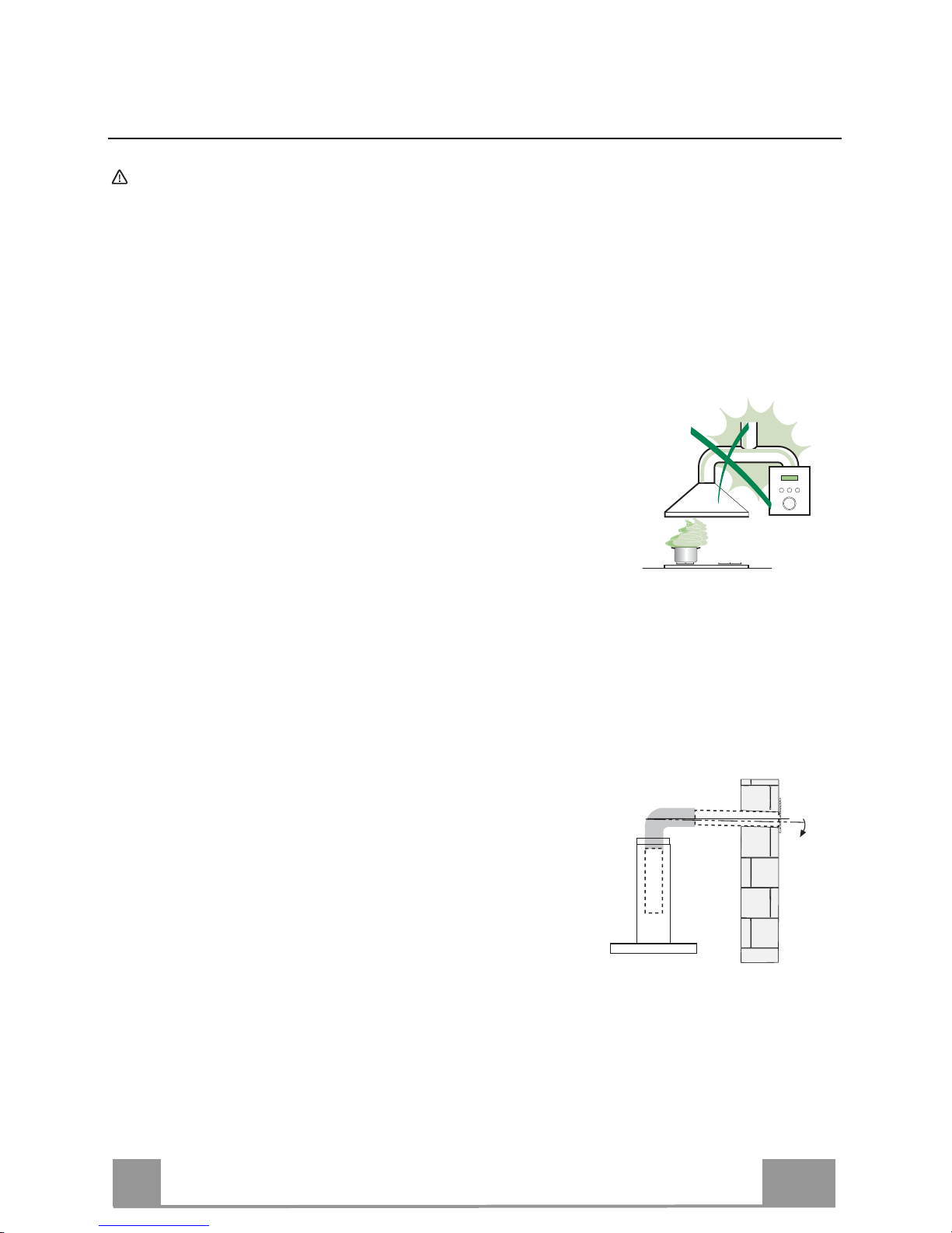
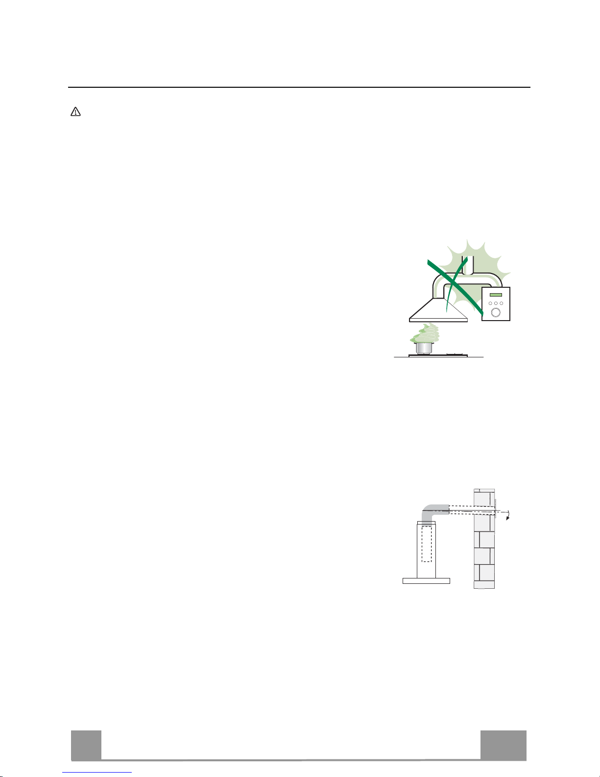
• Do not connect the extractor hood to exhaust ducts carrying combustion
fumes (boilers, fireplaces, etc.).
• If the extractor is used in conjunction with nonelectrical appliances (e.g. gas burning
appliances), a sufficient degree of aeration must
be guaranteed in the room in order to prevent the
backflow of exhaust gas. The kitchen must have
an opening communicating directly with the open
air in order to guarantee the entry of clean air.
When the cooker hood is used in conjunction with
appliances supplied with energy other than electric, the negative pressure in
the room must not exceed 0,04 mbar to prevent fumes being drawn back
into the room by the cooker hood.
• In the event of damage to the power cable, it must be replaced by the
manufacturer or by the technical service department, in order to prevent any
risks.
2°

EN
5
5
• If the instructions for installation for the gas hob specify a greater distance
specified above, this has to be taken into account. Regulations concerning
the discharge of air have to be fulfilled.
• Use only screws and small parts in support of the hood.
Warning: Failure to install the screws or fixing device in accordance with
these instructions may result in electrical hazards.
• Connect the hood to the mains through a two-pole switch having a contact
gap of at least 3 mm.
USE
• The extractor hood has been designed exclusively for domestic use to
eliminate kitchen smells.
• Never use the hood for purposes other than for which it has been designed.
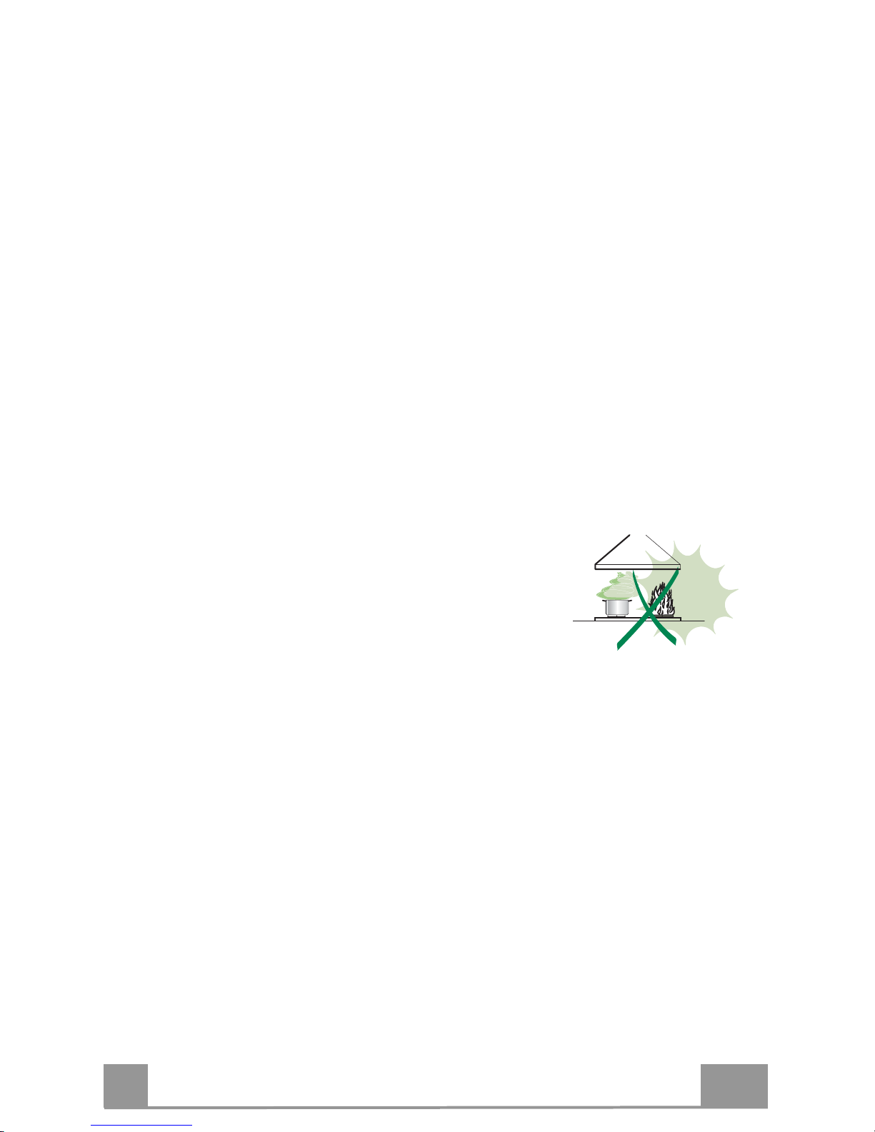
• Never leave high naked flames under the hood when it is in operation.
• Adjust the flame intensity to direct it onto the bottom of the pan only, making
sure that it does not engulf the sides.
• Deep fat fryers must be continuously monitored
during use: overheated oil can burst into flames.
• Do not flambè under the range hood; risk of fire.
• This appliance can be used by children aged from
8 years and above and persons with reduced
physical, sensory or mental capabilities or lack of
experience and knowledge if they have been given supervision or instruction
concerning use of the appliance in a safe way and understand the hazards
involved. Children shall not play with the appliance. Cleaning and user
maintenance shall not be made by children without supervision.

EN
6
6
• If the instructions for installation for the gas hob specify a greater distance
specified above, this has to be taken into account. Regulations concerning
the discharge of air have to be fulfilled.
• Use only screws and small parts in support of the hood.
Warning: Failure to install the screws or fixing device in accordance with
these instructions may result in electrical hazards.
• Connect the hood to the mains through a two-pole switch having a contact
gap of at least 3 mm.
USE
• The extractor hood has been designed exclusively for domestic use to
eliminate kitchen smells.
• Never use the hood for purposes other than for which it has been designed.
• Never leave high naked flames under the hood when it is in operation.
• Adjust the flame intensity to direct it onto the bottom of the pan only, making
sure that it does not engulf the sides.
• Deep fat fryers must be continuously monitored
during use: overheated oil can burst into flames.
• Do not flambè under the range hood; risk of fire.
• This appliance can be used by children aged from
8 years and above and persons with reduced
physical, sensory or mental capabilities or lack of
experience and knowledge if they have been given supervision or instruction
concerning use of the appliance in a safe way and understand the hazards
involved. Children shall not play with the appliance. Cleaning and user
maintenance shall not be made by children without supervision.
EN
7
7
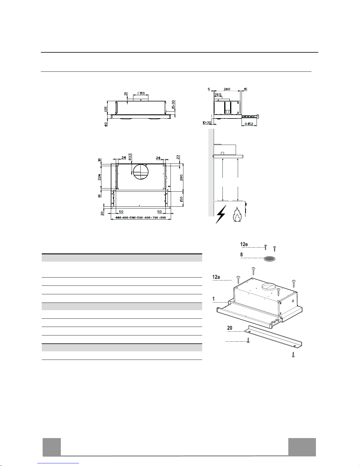
CHARACTERISTICS
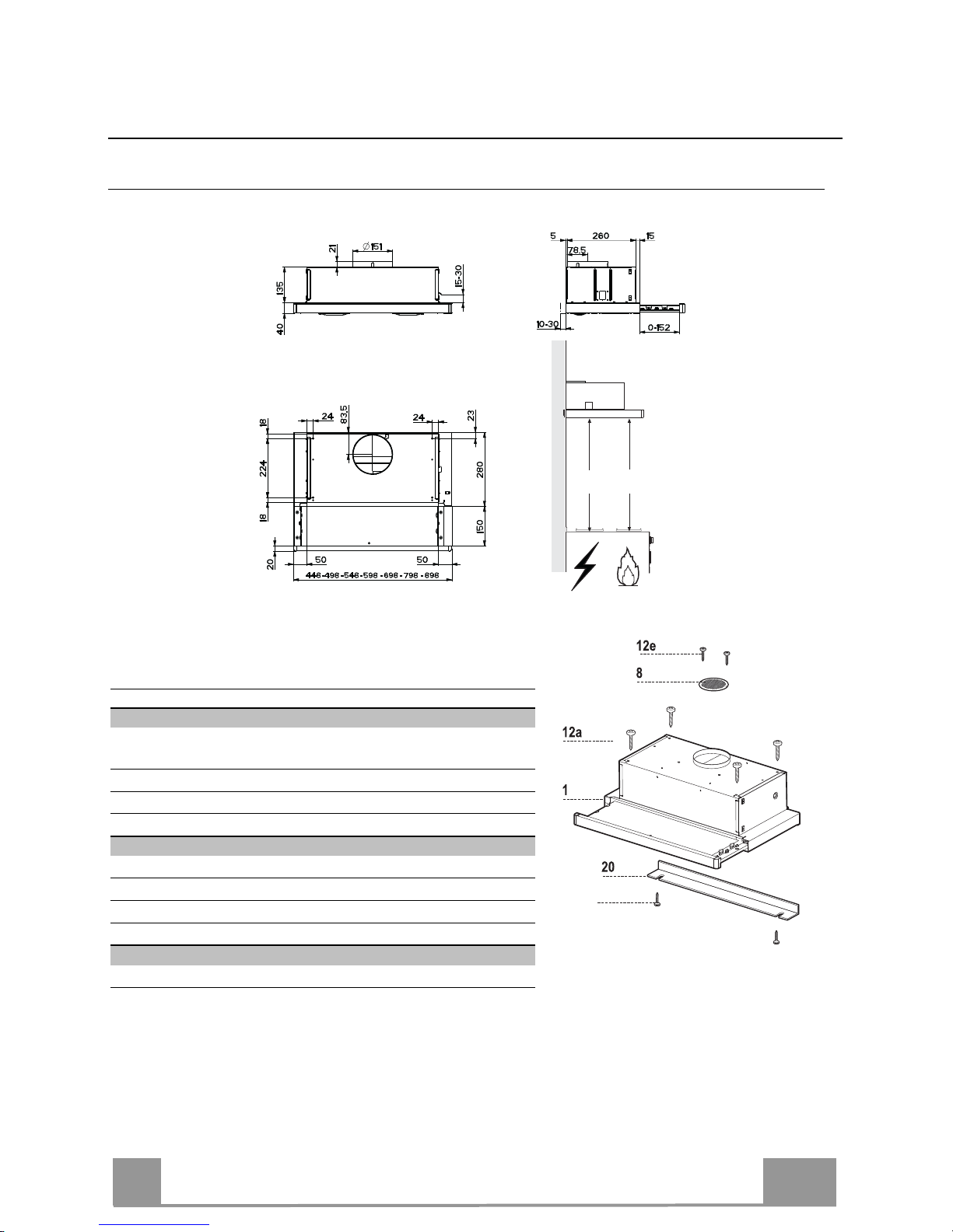
Dimensions
Min.
500mm
Min.
650mm
Components
Ref. Q.ty Product Components
1 1 Hood Body, complete with: Controls, Light, Blower,
Filters
8 1 Directional Air Outlet grille
20 1 Closing element
Ref. Q.ty Installation Components
12a 4 Screws 4,2 x 44,4
12b 2 Screws 4,2 x 12,7
12e 2 Screws 2,9 x 9,5
Q.ty Documentation
1 Instruction Manual
12b
EN
8
8
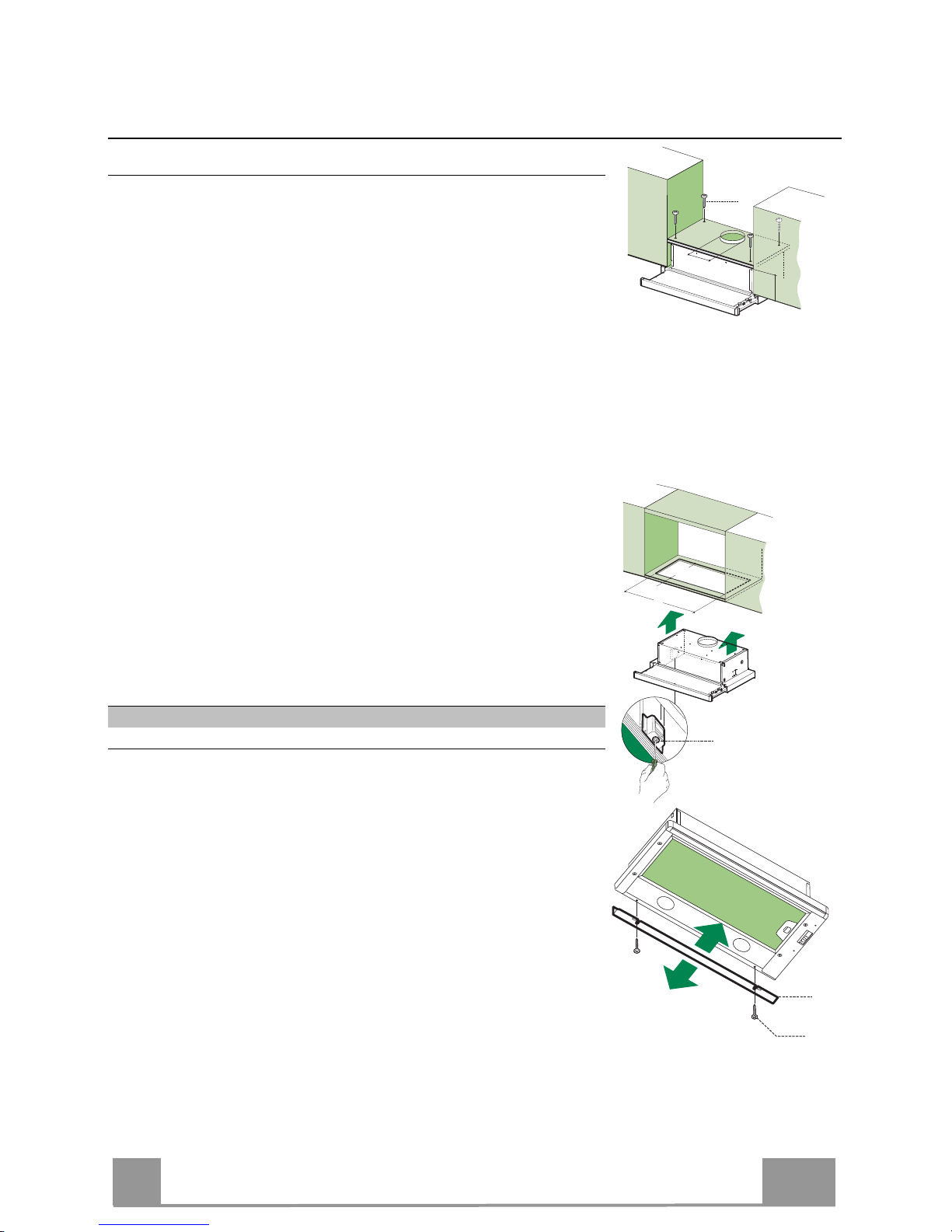
INSTALLATION
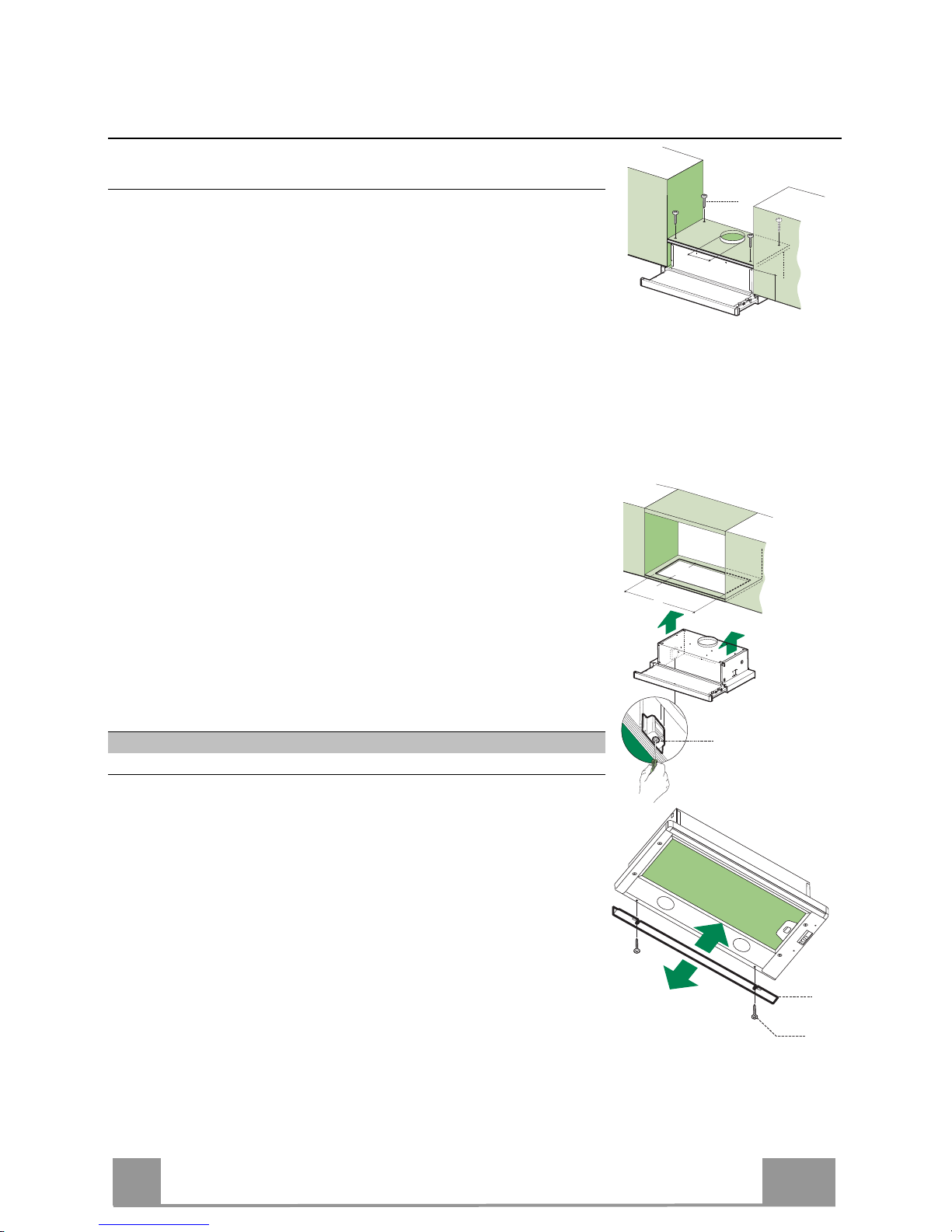
Drilling the Support surface and Fitting the Hood
SCREW FITTING
• The hood support surface must be 135 mm above the bottom
surface of the wall units.
• Drill the support with a ø 4,5 mm drill bit, using the drilling
template provided.
• Cut a hole ø 150 mm in size on the support surface, using the
drilling template provided.
• Fix using the 4 screws 12a (4,2 x 44,4) provided.
12a
135
150
SNAP-ON FITTING
• The hood can be installed either directly on the bottom surface
of the wall units using snap-on side supports.
• Cut a fitted opening in the bottom surface of the wall unit, as
shown.
• Insert the hood until the side supports snap into place.
• Lock in position by tightening the screws Vf from underneath
the hood.
Hood Type 45 50 55 60 70 80 90
L1 360 410 460 510 610 710 810
15
262
L1
Vf
CLOSING ELEMENT
• The space between the edge of the hood and the rear wall can
be closed by applying the element 20 provided, using the
screws 12b.
20
12b

EN
9
9
Connections
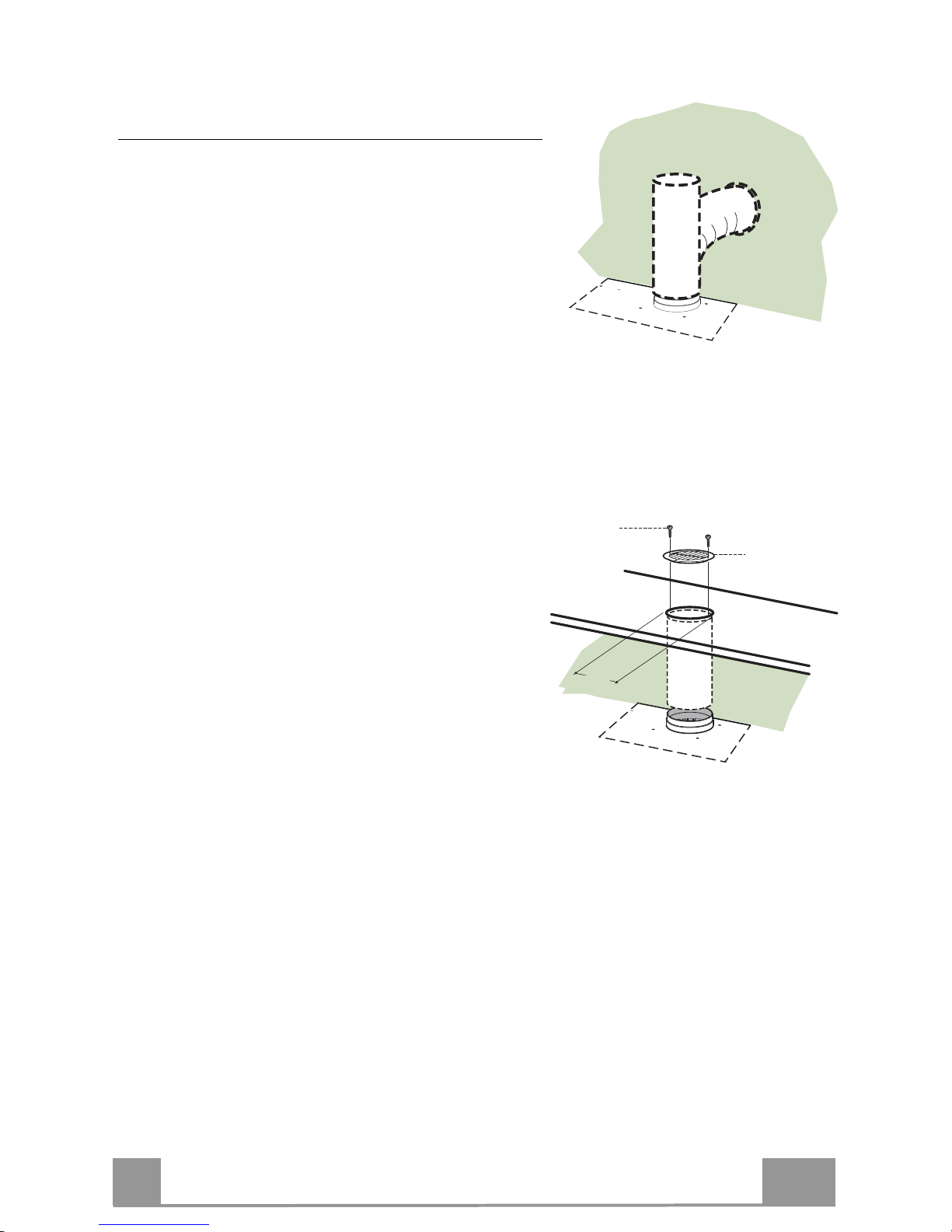
DUCTED VERSION AIR EXHAUST SYSTEM
When installing the ducted version, connect the hood to
the chimney using either a flexible or rigid
pipe ø 150 mm, the choice of which is left to the installer.
• Fix the pipe in position using sufficient pipe clamps
(not supplied).
• Remove any activated charcoal filters.
ø 150
RECIRCULATION VERSION AIR OUTLET
• Cut a hole ø 150 mm in the wall unit over the hood.
• Connect the hood body outlet to the top part of the
wall unit using a rigid or flexible pipe ø 150 mm, to
be selected by the installer.
• Fix the pipe in position using sufficient pipe clamps
(not supplied).
• Fix the directional grille 8 on the recirculation air
outlet using the 2 screws 12e (2,9 x 9,5) provided.
• Ensure that the activated charcoal filters have been
inserted.
ø 150
8
12e
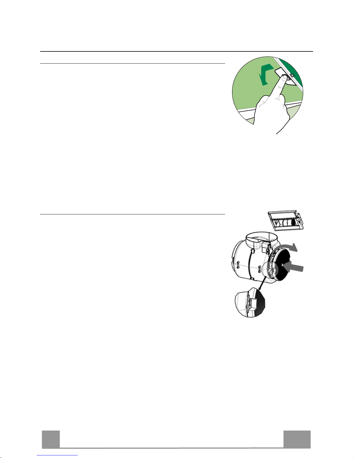
ELECTRICAL CONNECTION
• Connect the hood to the mains through a two-pole switch having a contact gap of at least 3
mm.
• When opening the sliding carriage for the first time after installing the hood, pull it out
briskly until it clicks.
EN
1
10
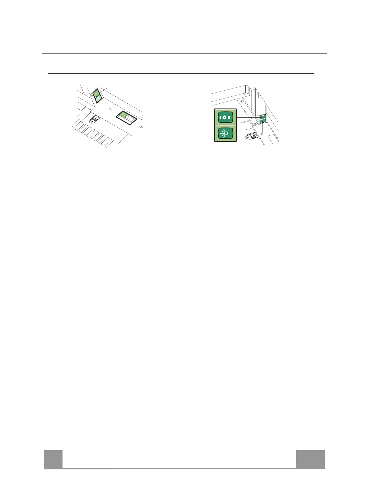
USE
Control panel
L Light Switches the lighting system
on and off.
M Motor Switches the extractor motor
on and off.
V Speed Sets the operating speed of
the extractor:
1. Low speed, used for a
continuous and silent air
change in the presence of
light cooking vapour.
2. Medium speed, suitable
for most operating conditions given the optimum
treated air flow/noise
level ratio.
3. Maximum speed, used for
eliminating the highest
cooking vapour emission,
including long periods.
L Light Switches the lighting system
on and off.
M Motor Switches the extractor motor
on and off.
V Speed Sets the operating speed of
the extractor:
1. Low speed, used for a
continuous and silent air
change in the presence of
light cooking vapour.
2. Medium speed, suitable
for most operating conditions given the optimum
treated air flow/noise
level ratio.
L
M - V
0
1
0
1
2
3
L
M-V

EN
1
11
MAINTENANCE
Grease filters
CLEANING METAL CASSETTE GREASE FILTERS
• The filters must be cleaned every 2 months, or more frequently
in case of particularly heavy use of the hood. Filters can be
washed in a dishwasher.
• Pull out the sliding suction panel.
• Remove the filters one by one, after having disconnected the
relative fastening elements.
• Wash the filters, taking care not to bend them. Let them get dry
before refitting them. (The colour of the filter surface may
change throughout the time but this has no influence to the filter efficiency).
• When refitting the filters, make sure that the handle is visible
on the outside.
• Close the sliding suction panel.
Charcoal filter (Recycling version)
REPLACING CHARCOAL FILTERS
Warning: Turn the lights off and wait until the lamps cool down
before you change the odour filter.
• These filters are not washable and cannot be regenerated, and
must be replaced approximately every four months or more
frequently by particularly heavy use.
• Pull out the sliding suction panel.
• Remove the grease filters.
• Remove the saturated carbon filter by releasing the fixing
hooks
• Fit the new filter by hooking it into its seating.
• Replace the grease filters.
• Close the sliding suction panel.

EN
1
12
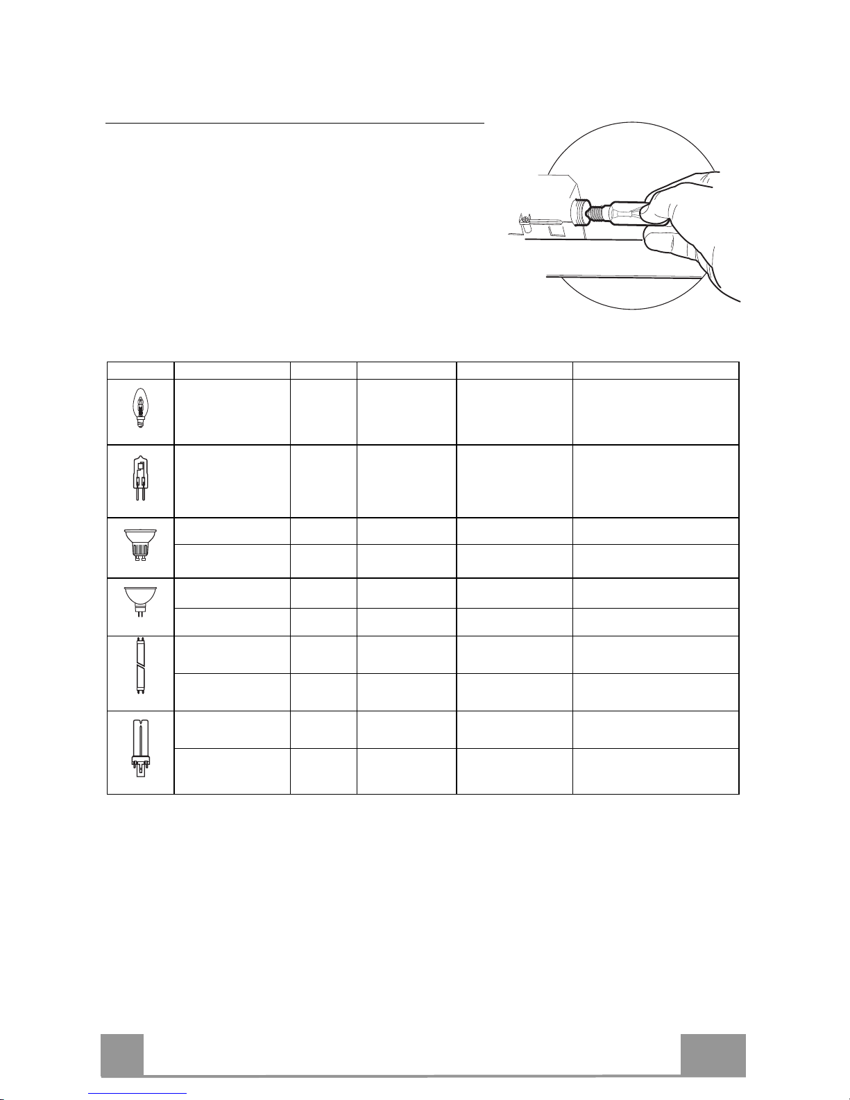
Lighting
LIGHT REPLACEMENT
28W-40W light.
• Remove the metal grease filters.
• Unscrew the bulbs and replace them with new ones
having the same characteristics.
• Replace the metal grease filters.
Lamp Power (W) Socket Voltage (V) Dimension (mm) ILCOS Code
28 E14 220 – 240 104 x 35
HSGSB/C/UB-28-220/240-E14
20 G4 12 33 x 9 HSG/C/UB-20-12-G4
35 GU10 230 51 x 50,7 HAGS-35-230-GU10-51/40
50 GU10 230 51 x 50,7 HAGS-35-230-GU10-51/20
20 GU4 12 40 x 35 HRGS-20-12-GU4-35/30
20 GU5.3 12 46 x 51 HRGS-20-12-GU5.3-50/10
16 G13 95 720 x 26
FD--16/40/1B-E--G13--26/720
18 G13 57 589,8 x 26
FD--18/40/1B--E--G13--26/600
9 G23
60 (lamp)
220-240 (starter)
167 x 28 FSD-9/27/1B-I-G23
11 G23
91 (lamp)
220-240 (starter)
235,8 x 28 FSD-11/40/1B-I-G23
IT
1
13
CONSIGLI E SUGGERIMENTI
Le Istruzioni per l’uso si riferiscono ai diversi modelli di questo
apparecchio. Pertanto, si potrebbero trovare descrizioni di singole
caratteristiche che non appartengono al proprio apparecchio specifico.
INSTALLAZIONE
• Il fabbricante non potrà ritenersi responsabile per eventuali danni risultanti
da un’installazione o utilizzazione impropria.
• La distanza minima di sicurezza tra il piano cottura
e la cappa aspirante è di 650 mm (alcuni modelli
possono essere installati a un’altezza inferiore;
vedere il paragrafo relativo alle dimensioni di lavoro
e all'installazione).
• Controllare che la tensione di rete corrisponda a
quella indicata sulla targa dati applicata all’interno
della cappa.
• Per gli apparecchi di Classe I, controllare che la rete di alimentazione
domestica disponga di un adeguato collegamento a massa.
Collegare l'aspiratore al condotto dei fumi mediante un tubo con diametro
minimo di 120 mm. Il percorso dei fumi deve essere il più corto possibile.
• Non collegare la cappa aspirante ai condotti fumari che trasportano fumi di
combustione (per es. caldaie, camini ecc.).
• Se l’aspiratore è utilizzato in combinazione con
apparecchi non elettrici (per es. apparecchi a gas),
deve essere garantito un sufficiente grado di
aerazione nel locale per impedire il ritorno di flusso
dei gas di scarico. La cucina deve avere un'apertura
comunicante direttamente con l'esterno per garantire
l'afflusso di aria pulita. Quando la cappa per cucina è utilizzata in
combinazione con apparecchi non alimentati dalla corrente elettrica, la
pressione negativa nel locale non deve superare 0,04 mbar per evitare che i
fumi vengano riaspirati nel locale dalla cappa.
• In caso di danneggiamento del cavo di alimentazione, occorre farlo sostituire
dal produttore o dal reparto di assistenza tecnica per evitare qualsiasi
rischio.
2°

IT
1
14
• Se le istruzioni di installazione del piano cottura a gas specificano una
distanza maggiore di quella sopra indicata, è necessario tenerne conto.
Devono essere rispettate tutte le normative riguardanti lo scarico dell'aria.
• Usare solo viti e minuteria di tipo idoneo per la cappa.
Avvertenza: la mancata installazione delle viti o dei dispositivi di fissaggio in
conformità alle presenti istruzioni può comportare rischi di scosse elettriche.
• Collegare la cappa all'alimentazione di rete mediante un interruttore bipolare
con distanza tra i contatti di almeno 3 mm.
USO
• La cappa aspirante è progettata esclusivamente per l’uso domestico allo
scopo di eliminare gli odori dalla cucina.
• Non usare mai la cappa per scopi diversi da quelli per cui è stata progettata.
• Non lasciare mai fiamme alte sotto la cappa quando è in funzione.
• Regolare l'intensità della fiamma in modo da dirigerla esclusivamente verso
il fondo del recipiente di cottura, assicurandosi che non ne avvolga i lati.
• Le friggitrici devono essere costantemente
controllate durante l’uso: l’olio surriscaldato
potrebbe incendiarsi.
• Non cuocere al flambé sotto la cappa: si potrebbe
sviluppare un incendio.
• Questo apparecchio può essere utilizzato da
bambini di età non inferiore a 8 anni e da persone con ridotte capacità psicofisico-sensoriali o con esperienza e conoscenze insufficienti, purché
attentamente sorvegliati e istruiti su come utilizzare in modo sicuro
l'apparecchio e sui pericoli che ciò comporta. Assicurarsi che i bambini non
giochino con l'apparecchio. Pulizia e manutenzione da parte dell'utente non
devono essere effettuate da bambini, a meno che non siano sorvegliati.
IT
1
15
• Se le istruzioni di installazione del piano cottura a gas specificano una
distanza maggiore di quella sopra indicata, è necessario tenerne conto.
Devono essere rispettate tutte le normative riguardanti lo scarico dell'aria.
• Usare solo viti e minuteria di tipo idoneo per la cappa.
Avvertenza: la mancata installazione delle viti o dei dispositivi di fissaggio in
conformità alle presenti istruzioni può comportare rischi di scosse elettriche.
• Collegare la cappa all'alimentazione di rete mediante un interruttore bipolare
con distanza tra i contatti di almeno 3 mm.
USO
• La cappa aspirante è progettata esclusivamente per l’uso domestico allo
scopo di eliminare gli odori dalla cucina.
• Non usare mai la cappa per scopi diversi da quelli per cui è stata progettata.
• Non lasciare mai fiamme alte sotto la cappa quando è in funzione.
• Regolare l'intensità della fiamma in modo da dirigerla esclusivamente verso
il fondo del recipiente di cottura, assicurandosi che non ne avvolga i lati.
• Le friggitrici devono essere costantemente
controllate durante l’uso: l’olio surriscaldato
potrebbe incendiarsi.
• Non cuocere al flambé sotto la cappa: si potrebbe
sviluppare un incendio.
• Questo apparecchio può essere utilizzato da
bambini di età non inferiore a 8 anni e da persone con ridotte capacità psicofisico-sensoriali o con esperienza e conoscenze insufficienti, purché
attentamente sorvegliati e istruiti su come utilizzare in modo sicuro
l'apparecchio e sui pericoli che ciò comporta. Assicurarsi che i bambini non
giochino con l'apparecchio. Pulizia e manutenzione da parte dell'utente non
devono essere effettuate da bambini, a meno che non siano sorvegliati.
IT
1
16
CARATTERISTICHE
Ingombro
Min.
500mm
Min.
650mm
Componenti
Rif. Q.tà Componenti di Prodotto
1 1 Corpo Cappa completo di: Comandi, Luce, Gruppo
Ventilatore, Filtri
8 1 Griglia direzionata Uscita Aria
20 1 Profilo chiusura
Rif. Q.tà Componenti di Installazione
12a 4 Viti 4,2 x 44,4
12b 2 Viti 4,2 x 12,7
12e 2 Viti 2,9 x 9,5
Q.tà Documentazione
1 Libretto Istruzioni
12b
IT
1
17
INSTALLAZIONE
Foratura Piano di supporto e Montaggio Cappa
MONTAGGIO CON VITI
• Il Piano di supporto della Cappa deve essere rientrante di 135
mm dal Piano inferiore dei Pensili.
• Forare ø 4,5 mm il supporto utilizzando la Dima di foratura in
dotazione.
• Praticare un foro ø 150 mm sul Piano di supporto, utilizzando
la Dima di foratura in dotazione.
• Fissare con 4 Viti 12a (4,2 x 44,4) in dotazione.
12a
135
150
MONTAGGIO CON FISSAGGIO A SCATTO
• La Cappa può essere installata direttamente sul piano inferiore
dei Pensili con i Supporti laterali a scatto.
• Praticare un incasso sul piano inferiore del Pensile, come indicato.
• Inserire la Cappa fino ad agganciare i Supporti laterali a scatto.
• Bloccare definitivamente serrando le Viti Vf dal sotto della
Cappa.
Tipo Cappa 45 50 55 60 70 80 90
L1 360 410 460 510 610 710 810
15
262
L1
Vf
PROFILO DI CHIUSURA
• Lo spazio tra il bordo della Cappa e la Parete di fondo può essere chiuso applicando il Profilo 20 in dotazione con le Viti
12b.
20
12b
IT
1
18
Connessioni
USCITA ARIA VERSIONE ASPIRANTE
Per installazione in Versione Aspirante collegare la
Cappa alla tubazione di uscita per mezzo di un tubo
rigido o flessibile di ø150 la cui scelta è lasciata all'installatore.
• Fissare il tubo con adeguate fascette stringitubo. Il
materiale occorrente non è in dotazione.
• Togliere eventuali Filtri Antiodore al Carbone attivo.
ø 150
USCITA ARIA VERSIONE FILTRANTE
• Praticare un foro ø 150 mm sull’eventuale Mensola
soprastante la Cappa.
• Collegare l’uscita del Corpo Cappa con la parte superiore del pensile per mezzo di un tubo rigido di ø 150
mm, la cui scelta è lasciata all’installatore.
• Fissare il tubo con adeguate fascette stringitubo. Il
materiale occorrente non è in dotazione.
• Fissare la Griglia direzionata 8 sull’uscita con 2 Viti
12e (2,9 x 9,5) in dotazione.
• Assicurarsi della presenza dei Filtri antiodore al Carbone attivo.
ø 150
8
12e
CONNESSIONE ELETTRICA
• Collegare la Cappa all’Alimentazione di Rete interponendo un Interruttore bipolare con apertura dei contatti di almeno 3 mm.
• Dopo aver installato la cappa è necessario per la prima volta aprire il carrello scorrevole energicamente fino a sentire lo scatto di fine corsa.

IT
1
19
USO
Quadro comandi
L Luci Accende e spegne l’Impianto
di Illuminazione.
M Motore Accende e spegne il motore
Aspirazione.
V Velocità Determina la velocità di e-
sercizio:
1. Velocità minima, adatta
ad un ricambio d’aria
continuo particolarmente
silenzioso, in presenza di
pochi vapori di cottura.
2. Velocità media, adatta
alla maggior parte delle
condizioni d’uso, dato
l’ottimo rapporto tra portata d’aria trattata e livello sonoro.
3. Velocità massima, adatta
a fronteggiare le massime
emissioni di vapore di
cottura, anche per tempi
prolungati.
L Luci Accende e spegne l’Impianto
di Illuminazione.
M Motore Accende e spegne il motore
Aspirazione.
V Velocità Determina la velocità di e-
sercizio:
1. Velocità minima, adatta
ad un ricambio d’aria
continuo particolarmente
silenzioso, in presenza di
pochi vapori di cottura.
2. Velocità media, adatta alla
maggior parte delle condizioni d’uso, dato
l’ottimo rapporto tra portata d’aria trattata e livello
sonoro.
L
M - V
0
1
0
1
2
3
L
M-V
IT
2
20
MANUTENZIONE
Filtri antigrasso
PULIZIA FILTRI ANTIGRASSO METALLICI AUTOPORTANTI
• Sono lavabili anche in lavastoviglie, e necessitano di essere
lavati ogni 2 mesi circa di utilizzo o più frequentemente, per un
uso particolarmente intenso.
• Estrarre il carrello aspirante.
• Togliere i Filtri uno alla volta, agendo sugli appositi agganci.
• Lavare i Filtri evitando di piegarli, e lasciarli asciugare prima
di rimontarli. (Un’eventuale cambiamento del colore della superficie del filtro, che potrebbe verificarsi nel tempo, non pregiudica assolutamente l’efficienza dello stesso.)
• Rimontarli facendo attenzione a mantenere la maniglia verso la
parte visibile esterna.
• Chiudere il carrello aspirante.
Filtri antiodore (Versione Filtrante)
SOSTITUZIONE
Attenzione: Spegnere le luci ed attendere il raffreddamento delle
lampade prima di effettuare la sostituzione del filtro antiodore.
• Non sono lavabili né rigenerabili, vanno sostituiti ogni 4 mesi
circa di utilizzo o più frequentemente, per un uso particolarmente intenso.
• Estrarre il carrello aspirante.
• Togliere i Filtri Antigrasso
• Rimuovere il Filtro antiodore al Carbone attivo saturo, agendo
sugli appositi agganci.
• Rimontare i Filtri antigrasso.
• Richiudere il carrello aspirante.
IT
2
21
Illuminazione
SOSTITUZIONE LAMPADE
Lampade da 28W-40W
• Togliere i Filtri antigrasso metallici.
• Svitare le Lampade e sostituirle con nuove di uguali
caratteristiche.
• Rimontare i Filtri antigrasso metallici.
Lampada Assorbimento (W) Attacco Voltaggio (V) Dimensione (mm) Codice ILCOS
28 E14 220 – 240 104 x 35
HSGSB/C/UB-28-220/240-E14
20 G4 12 33 x 9 HSG/C/UB-20-12-G4
35 GU10 230 51 x 50,7 HAGS-35-230-GU10-51/40
50 GU10 230 51 x 50,7 HAGS-35-230-GU10-51/20
20 GU4 12 40 x 35 HRGS-20-12-GU4-35/30
20 GU5.3 12 46 x 51 HRGS-20-12-GU5.3-50/10
16 G13 95 720 x 26
FD--16/40/1B-E--G13--26/720
18 G13 57 589,8 x 26
FD--18/40/1B--E--G13--26/600
9 G23
60 (lampada)
220-240 (starter)
167 x 28 FSD-9/27/1B-I-G23
11 G23
91 (lampada)
220-240 (starter)
235,8 x 28 FSD-11/40/1B-I-G23
 Loading...