

Page 1

This manual is the intellectual property of Foxconn, Inc. Although the
information in this manual may be changed or modified at any time,
Foxconn does not obligate itself to inform the user of these changes.
Statement:
All trademarks are the property of their respective owners.
More information:
If you want more information about our products, please visit Foxconn’s
website: http://www.foxconnchannel.com
This product and its accessories are produced after 13th Aug., 2005 and
comply with the WEEE2002/96EC directive.
Version:
Trademark:
User’s Manual V1.0 for Q9657MC/G9657MC motherboard.
P/N:91-181965MC0E-00-G
Symbol description:
Note: refers to important information that can help you to use motherboard
better.
Attention: indicates that it may damage hardware or cause data loss,
and tells you how to avoid such problems.
Warning: means that a potential risk of property damage or physical
injury exists.
Page 2

Declaration of conformity
HON HAI PRECISION INDUSTRY COMPANY LTD
66 , CHUNG SHAN RD., TU-CHENG INDUSTRIAL DISTRICT,
TAIPEI HSIEN, TAIWAN, R.O.C.
declares that the product
Motherboard
Q9657MC/G9657MC
is in conformity with
(reference to the specification under which conformity is declared in
accordance with 89/336 EEC-EMC Directive)
þ EN 55022: 1998/A2: 2003Limits and methods of measurements of radio disturbance
characteristics of information technology equipment
þ EN 61000-3-2/:2000 Electromagnetic compatibility (EMC)
Part 3: Limits
Section 2: Limits for harmonic current emissions
(equipment input current <= 16A per phase)
þ EN 61000-3-3/A1:2001 Electromagnetic compatibility (EMC)
Part 3: Limits
Section 2: Limits of voltage fluctuations and flicker in low-voltage
supply systems for equipment with rated current <= 16A
þ EN 55024/A2:2003 Information technology equipment-Immunity characteristics limits
and methods of measurement
Signature : Place / Date : TAIPEI/2006
Printed Name : James Liang Position/ Title : Assistant President
Page 3

Declaration of conformity
Trade Name: Foxconn
Model Name: Q9657MC/G9657MC
Responsible Party: PCE Industry Inc.
Address: 458 E. Lambert Rd.
Fullerton, CA 92835
Telephone: 714-738-8868
Facsimile: 714-738-8838
Equipment Classification: FCC Class B Subassembly
Type of Product: Motherboard
Manufacturer: HON HAI PRECISION INDUSTRY
COMPANY LTD
Address: 66 , CHUNG SHAN RD., TU-CHENG
INDUSTRIAL DISTRICT, TAIPEI HSIEN,
TAIWAN, R.O.C.
Supplementary Information:
This device complies with Part 15 of the FCC Rules. Operation is subject to the following two conditions : (1) this device may not cause harmful interference, and (2) this
device must accept any interference received, including interference that may cause
undesired operation.
Tested to comply with FCC standards.
Signature : Date : 2006
Page 4

Product Introduction
Main Features........................................................................................2
Layout......................................................................................................4
Rear I/O Ports.........................................................................................5
Installation Instructions
CPU.........................................................................................................7
Memory..................................................................................................10
Power Supply........................................................................................11
Other Connectors................................................................................12
Expansion Slots...................................................................................16
Jumpers...............................................................................................17
BIOS Description
Enter BIOS Setup.................................................................................19
Main menu............................................................................................19
Product Information.............................................................................21
Standard CMOS Features...................................................................22
Advanced BIOS Features....................................................................25
Advanced Chipset Features...............................................................27
Integrated Peripherals........................................................................28
Power Management Setup.................................................................32
PnP/PCI Configurations......................................................................35
PC Health Status.................................................................................36
Frequency Control...............................................................................38
Load Defaults Setting.........................................................................39
Set Supervisor/User Password.........................................................39
Save & Exit Setup.................................................................................40
Exit Without Saving..............................................................................40
Table of Contents
Chapter
11
Chapter
2
2
Chapter
3
3
Page 5

Driver CD Introduction
Utility CD content.................................................................................42
Install drivers........................................................................................42
Table of Contents
4
4
Chapter
Page 6

1.Attach the CPU and heatsink using silica gel to ensure full contact.
2.It is suggested to select high-quality, certified fans in order to avoid
damage to the motherboard and CPU due high temperatures.
3.Never turn on the machine if the CPU fan is not properly installed.
4.Ensure that the DC power supply is turned off before inserting or
removing expansion cards or other peripherals, especially when
you insert or remove a memory module. Failure to switch off the DC
power supply may result in serious damage to your system or
memory module.
Attention:
We cannot guarantee that your system will operate normally while
over-clocked. Normal operation depends on the over-clock capacity
of your device.
Attention:
Attention:
Since BIOS programs are upgraded from time to time, the BIOS
description in this manual is just for reference. We do not guarantee
that the content of this manual will remain consistent with the actual
BIOS version at any given time in the future.
Attention:
The pictures of objects used in this manual are just for your reference.
Please refer to the physical motherboard.
Page 7

This manual is suitable for motherboard of Q9657MC/
G9657MC. Each motherboard is carefully designed for the
PC user who wants diverse features.
-L with onboard 10/100M LAN (Default is omitted.)
-K with onboard Gigabit LAN
-6 with 6-Channel audio (Default is omitted.)
-8 with 8-Channel audio
-E with 1394
-S with SATA
-2 with DDR2
-Rwith RAID
-Hcomplay with RoHS directives
You can find PPID label on the motherboard. It indicates the
functions that the motherboard has.
For example:
The letters on the black mark of the PPID label mean the
motherboard supports 6-Channel Audio (-6)(default), 1394
port (-E), onboard 10/100M LAN (-L)(default), SATA connectors (-S).
Page 8
Chapter
Thank you for buying Foxconn’s Q/G9657MC series
motherboard. This series of motherboard is one of our new
products, and offers superior performance, reliability and
quality, at a reasonable price. This motherboard adopts the
advanced Intel® Q/G965 + ICH8DO/ICH8DH chipset, providing
users a computer platform with a high integration-compatibility-performance price ratio.
This chapter includes the following information:
v Main Features
v Layout
v Rear I/O Ports
1
1
Page 9

Chapter 1 Product Introduction
2
Main Features
Size
· mATX form factor of 9.6 inch x 9.6 inch
Microprocessor
· Supports Intel® CoreTM 2 Duo, Pentium® D,Pentium® 4,Celeron® D proces-
sors in an LGA775 package
· Supports FSB at 533 MHz /800 MHz /1066 MHz
· Supports Hyper-Threading technology
Chipset
· Intel® Q/G965 (North Bridge) + ICH8DO/ICH8DH (South Bridge)
System Memory
· Four 240-pin DIMM slots
· Supports Dual-Channel DDR2 533/667/800
· Supports up to 8GB DDR2 memory
USB 2.0 Ports
· Supports hot plug
·Ten USB 2.0 ports (four rear panel ports, three onboard USB headers
providing six extra ports)
· Supports wake-up from S1 and S3 mode
·Supports USB 2.0 protocol up to 480Mbps transmission rate
Onboard Serial ATA II
· 300MBps data transfer rate
· Supports hot plug and NCQ (Native Command Queuing )
·Six Serial ATA II connectors
Onboard LAN (-K)
· One LAN interface built-in onboard
· Supports 10/100/1000 Mbit/sec Ethernet
Page 10

3
Chapter 1 Product Introduction
Onboard 1394 (-E ) (optional)
· Supports hot plug
·With rate of transmission at 400 Mbps
·Connect with 2 independent 1394 units synchronously at most
Onboard Audio (-8)
· Supports S/PDIF output
· Supports Jack-Sensing function
· Supports Intel® High Definition Audio
Onboard Graphics
· Supports integrated VGA display function
PCI Express x16 Support
· Supports 4 GB/sec (8 GB/sec concurrent) bandwidth
· Low power consumption and power management features
Green Function
· Supports ACPI (Advanced Configuration and Power Interface)
· Supports S0 (normal), S1 (power on suspend), S3 (suspend to RAM), S4
(Suspend to disk - depends on OS), and S5 (soft - off)
Expansion Slots
· Two PCI slots
· One PCI Express x16 Graphics slot
· One PCI Express x1 slot
Page 11
Chapter 1 Product Introduction
4
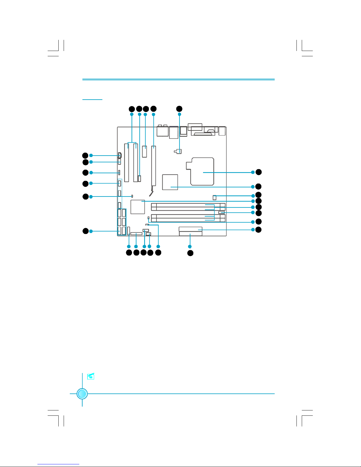
Layout
14. IrDA Header(optional)
15. SYS_FAN Connector
16. Clear CMOS Jumper
17. FDD Connector
18. 24-pin ATX Power Connector: PWR1
19. Chassis Intruder Connector
20. COM2 Connector
21. DDR2 DIMM Slots
22. South Bridge: ICH8DO/ICH8DH Chipset
23. CPU_Fan1 Connector
24. North Bridge: Intel® Q/G965 Chipset
25. LGA 775 CPU Socket
1. 4-pin ATX_12V Power Connector: PWR2
2. PCI Express x16 Slot
3. PCI Express x1 Slot
4. 1394 Connector (optional)
5. PCI Slots
6. AUX_IN Connector
7. Front Audio Connector
8. SPDIF_OUT Connector(optional)
9. Front USB Connectors
10.BIOS SEL1 Jumper
11. SATA II Connectors
12. Front Panel Connector
13. TPM Connector(optional)
Note: The above motherboard layout is provided for reference only, please refer
to the physical motherboard.
3
4 1
3
8
9
10
11
12131415 16
17
18
19
20
21
22
23
24
25
2
5
6
7
Page 12
5
Chapter 1 Product Introduction
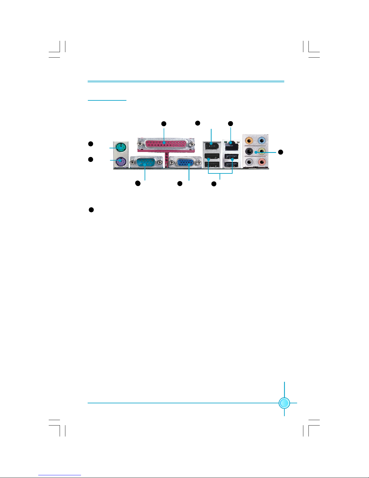
Rear I/O Ports
This motherboard provides the ports as below:
4
3
8
5
7
6
9
2
31 COM1
Parallel Port
(Print Port)
PS/2
Mouse Port
PS/2
Keyboard Port
VGA Connector
USB 2.0 Ports
Lan Port(-K)
1394 Connector
(optional)
Line in, Line out, Microphone, Rear, LEF/CEN, Side Jacks
When using 8-channel sound source, connect the front speaker to the green
audio output; connect the rear sound speaker to the black audio output; connect the center speaker/subwoofer to the orange audio output; connect the side
sound speaker to the grey audio output.
6
Page 13

Chapter 1 Product Introduction
6
This chapter introduces the hardware installation process, including the installation of the CPU, memory, power supply,
slots, and pin headers, and the mounting of jumpers. Caution should be exercised during the installation of these
modules. Please refer to the motherboard layout prior to any
installation and read the contents in this chapter carefully.
This chapter includes the following information:
v CPU
v Memory
v Power supply
v Other Connectors
v Expansion Slots
v Jumpers
Chapter
2
2
Page 14
Chapter 2 Installation Instructions
7
CPU
This motherboard supports Intel® CoreTM 2 Duo,Pentium® D, Pentium® 4,Celeron
®
D processors in an LGA775 package with a Front Side Bus (FSB) of 533/800/
1066 MHz.
For the detailed CPU support list on this motherboard, please visit the
website: http://w w w.fo xconn channel.com
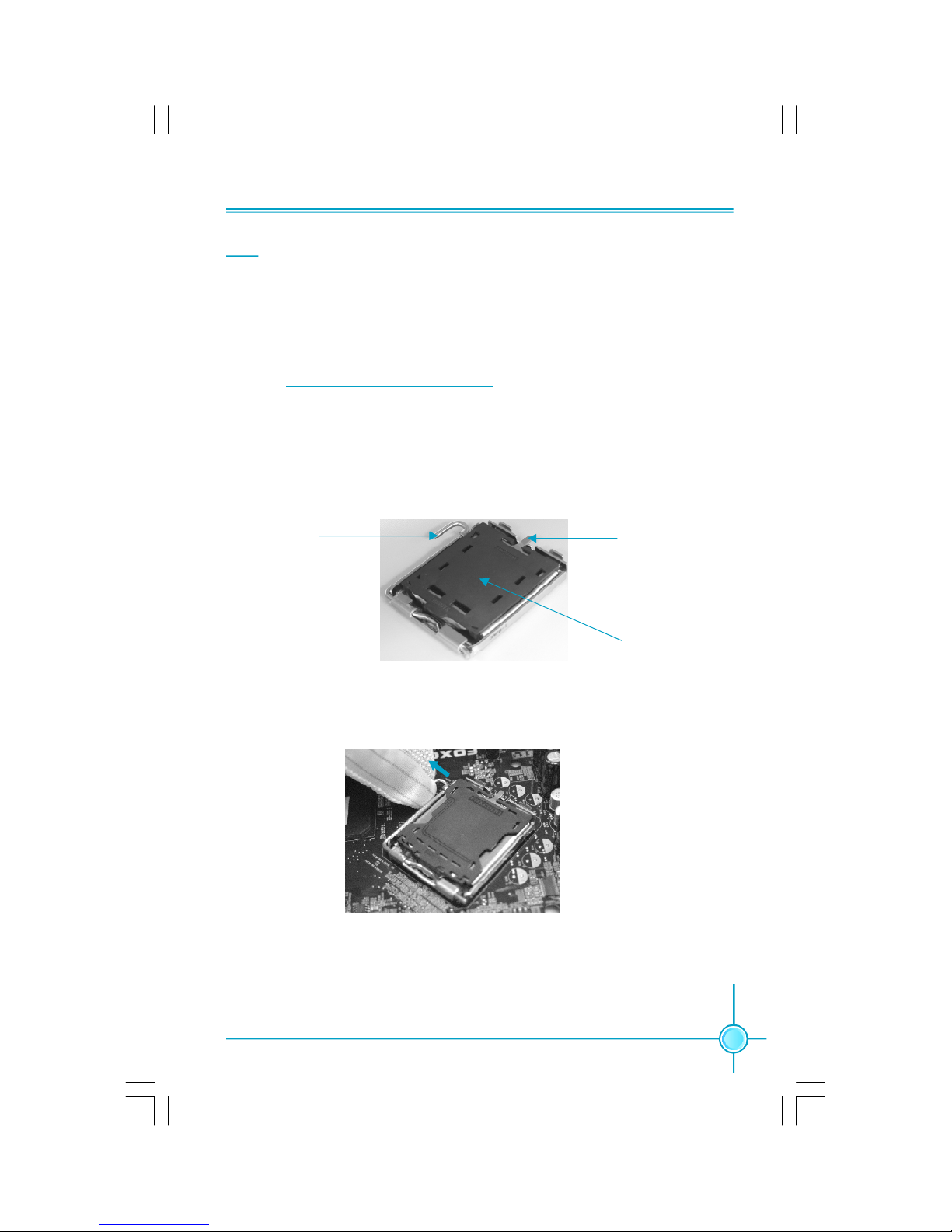
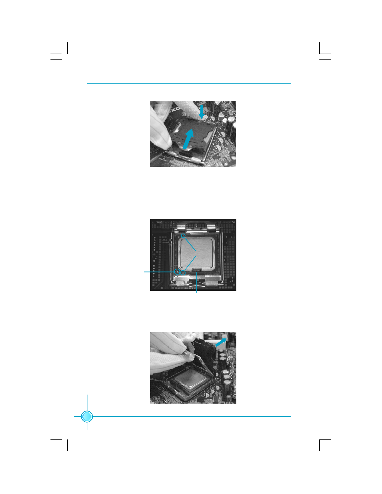
Installation of CPU
Below is the CPU socket illustration. Follow these procedures to install a CPU.
Load lever
Load plate
Protective cover
1. Use thumb and forefinger to hold the hook of the load lever and pull the lever
down and away from socket to unlock it. Lift the load lever.
2. Push down the rear tab with your forefinger to bring the front end of the load
plate up slightly. Open the load plate with thumb. Be careful not to touch the
contacts.
Page 15
Chapter 2 Installation Instructions
8
3. Hold CPU with thumb and forefinger. Ensure fingers align to socket cutouts.
Match the CPU triangle marker to Pin 1 position as shown below. The alignment
key also provides the orientation directed function. Lower the CPU straight down
without tilting or sliding the CPU in the socket.
4. After installing the CPU, remove the protective cover from load plate. The
protective cover is used to protect the contacts of the socket. Do not discard the
protective cover. Always replace the socket cover if the CPU is removed from the
socket.
Alignment Key
Socket Cutouts
Pin 1 position
Page 16

Chapter 2 Installation Instructions
9
Note :
Excessive temperatures will severely damage the CPU and
system. Therefore, you should install CPU cooling fan and make
sure that the cooling fan works normally at all times in order to
prevent overheating and damaging to the CPU. Please refer to your
CPU fan user guide to install it properly.
5. Close the load plate, and slightly push down the tongue side.
6. Lower the lever and lock it to the load plate, then the CPU is locked completely.
Page 17

Chapter 2 Installation Instructions
10
Memory
This motherboard includes four 240-pin slots with 1.8V for DDR2. So You must
install at least one memory bank to ensure normal operation.
Installation of DDR2 Memory
1.There is only one gap near the center of the DIMM slot, and the memory
module can be fixed in one direction only. Unlock a DIMM slot by pressing the
module clips outward.
2.Align the memory module to the DIMM slot, and insert the module vertically
into the DIMM slot.
3.The plastic clips at both sides of the DIMM slot will lock automatically.
128 Pins
112 Pins
For the detailed memory support list on this motherboard, please visit the
website: http://w w w.fo xconn channel.com
Page 18

Chapter 2 Installation Instructions
11
Power Supply
This motherboard uses an ATX power supply. In order to avoid damaging any
devices, make sure that they have been installed properly prior to connecting
the power supply.
24-pin ATX power connector: PWR1
PWR1 is the ATX power supply connector. Make
sure that the power supply cable and pins are
properly aligned with the connector on the
motherboard. Firmly plug the power supply cable
into the connector and make sure it is secure.
4-pin ATX_12 V Power Connector: PWR2
The 4-pin ATX 12V power supply connects to
PWR2 and provides power to the CPU.
4-pin ATX_12 V Power Connector
12V
GND
12V
3 1
4 2
GND
13
+3.3V
+5V
GND
+3.3V
GND
PWROK
+3.3V
24
+5V
GND
+3.3V
GND
GND
+5V
+5V
GND
PS-ON
-12V
12
1
GND
+5V
+
5V_AUX
+12V
+12V
RSVD
GND
24-pin ATX Power Connector
Page 19

Chapter 2 Installation Instructions
12
Other Connectors
This motherboard includes connectors for FDD device, Serial ATA devices, USB
devices, IR module, and others.
FDD Connector: FLOPPY
This motherboard includes a standard FDD connector, supporting 360K, 720K,
1.2M, 1.44M, and 2.88M FDDs.
Front Panel Connector: FP1
This motherboard includes one connector for connecting the front panel switch
and LED indicators.
14
13
2
1
FP1
HDD_LED
RESET
5V_SYS
PWRSW
NC
Key
LAN_LED
PWRLED
HDD LED Connector (HDD-LED)
The connector connects to the case’s HDD indicator LED indicating the activity
status of hard disks.
Reset Switch (RESET)
Attach the connector to the Reset switch on the front panel of the case; the
system will restart when the switch is pressed.
Power LED Connector (PWRLED)
Attach the connector to the power LED on the front panel of the case. The Power
LED indicates the system’s status. When the system is in S0 status, the LED is
on. When the system is in S1 status, the LED is blink; When the system is in S3,
S4, S5 status, the LED is off.
Power Switch Connector (PWRSW)
Attach the connector to the power button of the case. Pushing this switch allows
the system to be turned on and off rather than using the power supply button.
LAN LED Connector (LAN-LED)
The connector connects to the case’s LAN indicator LED indicating the activity
status of LAN.
Page 20

Chapter 2 Installation Instructions
13
1
F_AUDIO
PORT2_L
SENSE_SEND
PORT1_L
PORT1_R
PORT2_R
AUD_GND
PRESENCE_J
SENSE1_RETURN
SENSE2_RETURN
Empty
Audio Connector: F_AUDIO
The audio connector supports HD audio standard. It provides two kinds of
audio output choices: the Front Audio,
the Rear Audio. Front Audio supports
re-tasking function.
IrDA Connector: IR(optional)
This header supports wireless transmitting and receiving device. Before using
this function, configure the settings of
IR Mode from the “Integrated Peripherals” section of the CMOS Setup.
IR
1
+5V
GND
IRRX
IRTX
Empty
1394 Connector: F_1394 (optional)
The 1394 expansion cable can be connected to either the front (provided that
the front panel of your chassis is
equipped with the appropriate
interface) or real panel of the chassis.
12
GND
+12V
TPB -
GND
TPA -
+12V
TPB +
GND
TPA +
Empty
F_1394
910
SPDIF_OUT
1
SPDIF_OUT
+5V
GND
Empty
S/PDIF Out Connector: SPDIF_OUT
(optional)
The SPDIF OUT connector is capable of
providing digital audio to external
speaker or compressed AC3 data to an
external Dolby digital decoder.
Note: The empty pin of S/PDIF cable
should be aligned to empty pin of
S/PDIF out connector.
Page 21

Chapter 2 Installation Instructions
14
Serial ATA II Connectors: SATA_1, SATA_2,
SATA_3, SATA_4; SATA_5, SATA_6
The Serial ATA II connector is used to connect
the Serial ATA II device to the motherboard. These
connectors support the thin Serial ATA II cables
for primary storage devices. The current Serial
ATA II interface allows up to 300MB/s data transfer rate.
1
SATA_1/2/3/4/5/6
GND
GND GND
RX+
RX-TX-
TX+
Chassis Intruder Connector: INTR
The connector connects to the chassis security
switch on the case. The system can detect the
chassis intrusion through the status of this
connector. If the connector has been closed
once, the system will send a message.
INTR
1 INTRUDERJ 2 GND
Audio Connectors: AUX_IN
AUX_IN is Sony standard CD audio connectors,
it can be connected to a CD-ROM drive through
a CD audio cable.
AUX_IN
1
CD_R
GND
CD_L
COM Connector: COM2
This motherboard provides an additional serial
COM header for your machine.Connect one side
of a switching cable to the header, then attach
the serial COM device to the other side of the
cable.
COM2
SOUT
GND RLSD RI#
DTR#
DSR#
SIN
9
10
1
2
CTS#
RTS#
Empty
Page 22

Chapter 2 Installation Instructions
15
USB Headers: F_USB1, F_USB2, F_USB3
Besides four USB ports on the rear panel, the series of
motherboards also have three headers on board which
may connect to front panel USB cable (optional) to
provide additional six USB ports.
F_USB 1/2/3
1
5V_DUAL
D-
D+
D-
GND
GND
D+
NC
Empty
5V_DUAL
TPM
CK_33M_TPM
Empty
L_FRAMEJ
2
1
20
19
GND
ICH_P_PCIRSTJ
NC
L_AD3
3D3V_SYS
L_AD0NC
GND
NC
LPCPDJ
L_AD2
L_AD1
GND
NC
SERIRQ
NC
GND
TPM Connector: TPM (optional)
The TPM(Trusted Platform Module) provides the ability to the PC to run
applications more secure and to make transactions and communication more
trustworthy. To utilize this function, you should purchase addtional device and
install it.
Fan Connectors: CPU_FAN1, SYS_FAN
The fan speed can be detected and viewed in “PC Health Status” section of the
CMOS Setup. These fans will be automatically turned off after the system enters
S3, S4 and S5 mode.
SYS_FAN
+12V
GROUND
SENSE
1
CPU_FAN1
SENSE
GROUND
1
POWERCONTROL
Page 23

Chapter 2 Installation Instructions
16
Expansion Slots
This motherboard includes two32-bit master PCI slots,one PCI Express x 1 slot
and one PCI Express x 16 slot.
PCI Slots
The expansion cards can be installed in the two PCI slots. PCI slots support
cards such as a LAN card, USB card, SCSI card and other cards that comply
with PCI specifications.
PCI Express x1 Slot
This motherboard has one PCI Express x1 slot that designed to accommodate
less bandwidth-intensive cards, such as a modem or LAN card.
PCI Express x16 Slot
This motherboard has one PCI Express x16 slot that reserved for graphics or
video cards. The difference in bandwidth between the x16, x4 and x1 slot is
notable to be sure, with the x16 slot pushing 4GB/sec (8GB/sec concurrent) of
bandwidth, the PCI Express x4slot offering 500MB/sec,and the PCI Express x1
slot offering 250MB/sec.
Installing an expansion card
1.Before installing the expansion card, read carefully the documentation that
came withit and make the necessary hardware settings for the card.
2.Make sure to unplug the power cord before adding or removing any expan-
sion cards.
3.Remove the bracket opposite the slot that you intend to use.
4.Align the card connector with the slot and press firmly until the card is
completely seated in the slot.
5.Secure the card to the chassis with the screw you removed earlier.
For the detailed PCI Express cards support list on this motherboard, please
visit the website: http://www .fo xcon n channel.com
Page 24

Chapter 2 Installation Instructions
17
Jumpers
The users can change the jumper settings on this motherboard if needed. This
section explains how to use the various functions of this motherboard by changing the jumper settings. Users should read the following content carefully prior to
modifying any jumper settings.
Description of Jumpers
1. For the jumpers on this motherboard, pin 1 can be identified by the bold
silkscreen or by the silk-screen printed “ ” next to it. However, in this
manual, pin 1 is simply labeled as “1”.
2. The following table provides some explanation of the jumper pin settings.
User should refer to this when adjusting jumper settings.
Jumper Diagram Definition Description
1-2 Set pin1 and pin2 closed
2-3 Set pin2 and pin3 closed
Closed Set the pin closed
Open Set the pin opened
1
1
1
1
1
1
Clear CMOS Jumper: CLR_CMOS
The motherboard uses the CMOS RAM to store all
the set parameters. The CMOS can be cleared by
removing the CMOS jumper.
How to clear CMOS?
1. Turn off the AC power supply and connect pins 1
and 2 together using the jumper cap.
2. Return the jumper setting to normal (pins 2 and
3 together with the jumper cap).
3. Turn the AC power supply back on.
NORMAL
(Default)
CLR_CMOS
CLEAR
1 3 2
1 3 2
Warning:
1. Disconnect the power cable before adjusting the jumper settings.
2. Do not clear the CMOS while the system is turned on.
3. Do not unplug the BIOS SEL1 jumper randomly which defaults
SPI BIOS Mode.
Page 25

Chapter 3 BIOS Description
18
This chapter tells how to change system settings through the
BIOS Setup menus. Detailed descriptions of the BIOS parameters are also provided.
You have to run the Setup Program when the following cases
occur:
1.An error message appears on the screen during the system
POST process.
2.You want to change the default CMOS settings.
This chapter includes the following information:
v Enter BIOS Setup
v Main Menu
v Product Information
v Standard CMOS Features
v Advanced BIOS Features
v Advanced Chipset Features
v Integrated Peripherals
v Power Management Setup
v PnP/PCI Configurations
v PC Health Status
v Frequency Control
v Load Defaults Setting
v Set Supervisor/User Password
v Save & Exit Setup
v Exit Without Saving
Chapter
3
3
Page 26

Chapter 3 BIOS Description
19
Enter BIOS Setup
The BIOS is the communication bridge between hardware and software,
correctly setting up the BIOS parameters is critical to maintain optimal system
performance. Power on the computer, when the following message briefly
appears at the bottom of the screen during the POST (Power On Self Test),
press <Del> key to enter the Award BIOS CMOS Setup Utility.
Press TAB to show POST Screen, DEL to enter SETUP.
Main Menu
The main menu allows you to select from the list of setup functions and two exit
choices. Use the arrow keys to select among the items and press <Enter> to
accept or go to the sub-menu.
The items in the main menu are explained as below:
Product Information
The product information can be seen through this menu.
Standard CMOS Features
The basic system configuration can be set up through this menu.
Main Menu
Note:
We do not suggest that you change the default parameters in the
BIOS Setup, and we shall not be responsible for any damage that
result from any changes that you make.
Page 27

Chapter 3 BIOS Description
20
Advanced BIOS Features
The advanced system features can be set up through this menu.
Advanced Chipset Features
The values for the chipset can be changed through this menu, and the system performance can be optimized.
Integrated Peripherals
All onboard peripherals can be set up through this menu.
Power Management Setup
All the items of Green function features can be set up through this menu.
PnP/PCI Configurations
The system’s PnP/PCI settings and parameters can be modified through
this menu.
PC Health Status
This will display the current status of your PC.
Frequency Control
This menu is used to set the frequency.
Load Defaults Setting
The default BIOS settings can be loaded through this menu.
Set Supervisor Password
The supervisor password can be set up through this menu.
Set User Password
The user password can be set up through this menu.
Save & Exit Setup
Save CMOS value settings to CMOS and exit setup.
Exit Without Saving
Abandon all CMOS value changes and exit setup.
Page 28

Chapter 3 BIOS Description
21
Product Information
Product Information Menu
According to this menu, you can see the information of the product ,which
includes the system name, motherboard product name,system S/N,
motherboard S/N, system manufacture name, motherboard manufacture
name,system BIOS version, SMBIOS version, system BIOS ID, BIOS release
time and so on, and makes users to know the system information clearly.
Page 29

Chapter 3 BIOS Description
22
Standard CMOS Features
This sub-menu is used to set up the standard CMOS features, such as the date,
time, HDD model and so on. Use the arrow keys select the item to set up, and
then use the <PgUp> or <PgDn> keys to choose the setting values.
Date
This option allows you to set the desired date (usually as the current day) with
the <day><month><date><year> format.
Day—weekday from Sun. to Sat., defined by BIOS (read-only).
Month—month from Jan. to Dec..
Date—date from 1st to 31st, can be changed using the keyboard.
Year—year, set up by users.
Time
This option allows you to set up the desired time (usually as the current time)
with <hour><minute><second> format.
IDE Channel 0/1/2/3 Master, 0/1Slave
These categories identify the HDD types of 1 IDE channel installed in the computer system. There are three choices provided for the Enhanced IDE BIOS:
None, Auto, and Manual. “None” means no HDD is installed or set; “Auto” means
the system can auto-detect the hard disk when booting up; by choosing “Manual”
and changing Access Mode to “CHS”, the related information should be entered
manually. Enter the information directly from the keyboard and press < Enter>:
Cylinder number of cylinders Head number of heads
Precomp write pre-compensationLanding Zone landing zone
Sector number of sectors
Standard CMOS Features Menu
Page 30

Chapter 3 BIOS Description
23
Award (Phoenix) BIOS can support 3 HDD modes: CHS, LBA and Large or Auto mode.
CHS For HDD<528MB
LBA For HDD>528MB & supporting LBA (Logical Block Addressing)
Large For HDD>528MB but not supporting LBA
Auto Recommended mode
Drive A
This option allows you to select the kind of FDD to be installed, including “None”,
[360K, 5.25 in], [1.2M, 5.25 in], [720K, 3.5 in], [1.44M, 3.5 in] and [2.88 M, 3.5 in].
Halt On
This category determines whether or not the computer will stop if an error is
detected during powering up.
All Errors Whenever the BIOS detects a nonfatal error, the system
will stop and you will be prompted.
No Errors The system boot will not stop for any errors that may
be detected.
All, But Keyboard The system boot will not stop for a keyboard error; but
it will stop for all other errors.
All, But Diskette The system boot will not stop for a diskette error; but
it will stop for all other errors.
All, But Disk/Key The system boot will not stop for a keyboard or disk
error, but it will stop for all other errors.
Video
The following table is provided for your reference in setting the display mode for
your system.
EGA/VGA Enhanced Graphics Adapter / Video Graphic Array. For
EGA, VGA, SEGA, SVGA, or PGA monitor adapters.
CGA 40 Color Graphic Adapter, powering up in 40 column mode.
CGA 80 Color Graphic Adapter, powering up in 80 column mode.
MONO Monochrome adapter, including high resolution monochrome adapters.
Page 31

Chapter 3 BIOS Description
24
Memory
This is a Display-Only Category, determined by POST (Power On Self Test) of
the BIOS.
Base Memory The BIOS POST will determine the amount of base (or
conventional) memory installed in the system.
Extended Memory The BIOS determines how much extended memory
is present during the POST.
Total Memory Total memory of the system.
Page 32

Chapter 3 BIOS Description
25
Advanced BIOS Features
vHard Disk Boot Priority
This option is used to select the priority for HDD startup. After pressing
<Enter>, you can select the HDD using the <PageUp>/<PageDn> or Up/
Down arrow keys, and change the HDD priority using <+> or <->; you can
exit this menu by pressing <Esc>.
vVirus Warning
This option is used to set up the virus warning message for the IDE HDD boot
sector.
Note: Such function provides protection to the startup sector only;it does
not protect the entire hard disk.
vQuick Power On Self Test
This option is used to set the Quick Power On Self Test .
vFirst/Second/Third Boot Device
This option allows you to set the boot device’s sequence.
vBoot Other Device
With this function set to enable, the system will boot from some other devices if the first/second/third boot devices failed. The setting values are: Disabled and Enabled.
vBoot Up Floppy Seek
This option controls whether the BIOS checks for a floppy drive while booting
up. If it cannot detect one (either due to improper configuration or physical
unavailability), it will appear an error message. The available setting values
are: Disabled and Enabled.
Advanced BIOS Features Menu
Page 33

Chapter 3 BIOS Description
26
vBoot Up NumLock Status
This item defines if the keyboard Num Lock key is active when your system is
started. The available setting values are: On and Off.
vGate A20 Option
This option is used to set up the A20 signal control necessary for system is
started.
vSecurity Option
When it is set to “Setup”, a password is required to enter the CMOS Setup
screen; When it is set to “System”, a password is required not only to enter
CMOS Setup, but also to start up your PC.
vAPIC Mode
This option is used to enable or disable APIC function.
vMPS Version Control For OS
This option is used to set up the version of MPS Table used in OS.
vSilent Boot
The item is used to enable or disable the silent boot.
vConfiguration Table
The item is used to show summary screen.
vASF support
The item is used to enable or disable the ASF support.
vDMI Event Log
Enable the item, the system will store POST error messages to the DMI event
log.
vClear All DMI Event Log
When this item is selected to [Yes], the DMI event log will be cleared at next
POST stage, and then set this item to [No] automatic.
vView DMI Event Log
Press Enter to show all DMI event logs.
vMark DMI Events Log
This option is used to clear all DMI event logs immediately. Press Enter will
pop up a confirm screen. Hit [Y] and [Enter], then clear all DMI event logs right
now.
Page 34

Chapter 3 BIOS Description
27
Advanced Chipset Features
vAMT BIOS Support
This item is used to set whether the AMT BIOS support is enabled.
[VGA Setting]
vPEG/Onchip VGA Control
This item is used to enable or disable PEG and onboard VGA.
vOn-chip Frame Buffer Size
This item is used to set the VGA frame buffer size.
Note: This function does not work when the external display card is used.
vDVMT Mode
The item is used to set the DVMT mode.
vDVMT/FIXED Memory Size
The item is used to set the DVMT/FIXED memory size.
Advanced Chipset Features Menu
Page 35

Chapter 3 BIOS Description
28
Integrated Peripherals
vOnChip IDE Device
Press enter to set onchip IDE device.
vOnboard Device
Press enter to set onboard device.
vSuperIO Device
Press enter to set onboard SuperIO device.
Integrated Peripherals Menu
Page 36

Chapter 3 BIOS Description
29
vIDE HDD Block Mode
This option is used to set whether the IDE HDD block mode is allowed.
vIDE DMA transfer access
This option is used to set the IDE transfer access—with it set to Enabled, the
IDE Transfer Access uses the DMA mode; with it set to Disabled, the IDE
Transfer Access uses the PIO mode.
vIDE Primary Master/Slave PIO
These items let you assign which kind of PIO (Programmed Input/Output)
is used by IDE devices. Choose Auto to let the system auto detect which PIO
mode is best or select a PIO mode from 0-4.
vIDE Primary Master/Slave UDMA
UltraDMA technology provides faster access to IDE devices. If you install a
device that supports UltraDMA, change the appropriate item on this list to
Auto. The available setting values are: Disabled and Auto.
vOn-Chip Secondary PCI IDE
Use this item to enable or disable the Secondary PCI IDE channel that is integrated on the motherboard.
vIDE Secondary Master/Slave PIO
These two items allow you assign which kind of PIO(Programmed Input/
Output) is used by IDE devices. Choose Auto to let the system auto detect
which PIO mode is best or select a PIO mode from 0-4.
vIDE Secondary Master/Slave UDMA
UltraDMA technology provides faster access to IDE devices. If you install a
device that supports UltraDMA ,change the appropriate item on this list to
Auto.The available setting values are : Disabled and Auto.
vSATA Mode
This option is used to set the Serial ATA Mode.
OnChip IDE Device Menu
Page 37

Chapter 3 BIOS Description
30
vUSB Controller
This option is used to set whether the USB Controller is enabled. The
available setting values are: Disabled and Enabled.
vUSB 2.0 Controller
This option is used to set whether the USB 2.0 Controller is enabled.
vUSB Keyboard Support
This option is used to set whether the USB keyboard controller is enabled in a
legacy operating system (such as DOS).
vUSB Mouse Support
This option is used to set whether the USB mouse controller is enabled in a
legacy operating system (such as DOS).
vOnboard Lan Controller
This option is used to set whether the onboard LAN controller is enabled.
vAzalia Audio
This option is used to set whether onboard Azalia Audio is enabled.
v Onboard LAN Boot ROM
This option is used to decide whether to invoke the boot ROM of the onboard
LAN chip.
Onboard Device Menu
Page 38

Chapter 3 BIOS Description
31
vOnboard FDC Controller
This option is used to set whether the Onboard FDC Controller is enabled.
The available setting values are: Disabled and Enabled.
vOnboard Serial Port1/2
This option is used to assign the I/O address and interrupt request (IRQ) for
the onboard serial port .
Note: Do not try to set the same values for serial ports 1 and 2.
vOnboard Parallel Port
This option allows you to determine onboard parallel port controller I/O address and interrupt request (IRQ).
vParallel Port Mode
Select an address and corresponding interrupt for the onboard parallel port.
vECP Mode Use DMA
When the Parallel Port Mode is set to ECP or ECP+ EPP, this option is used to
select the channel for the ECP mode.
SuperIO Device Menu
Page 39

Chapter 3 BIOS Description
32
vPCI Express PM Function
Press Enter to set the PCI Express PM Function.
vACPI function
ACPI stands for “Advanced Configuration and Power Interface”. ACPI is a
standard that defines power and configuration management interfaces between an operating system and the BIOS. In other words, it is a standard that
describes how computer components work together to manage system
hardware. In order to use this function the ACPI specification must be supported by the OS (for example, Windows2000 or WindowsXP). The available
setting values are: Enabled and Disabled.
v ACPI Suspend Type
This option is used to set the energy saving mode of the ACPI function.
When you select “S1 (POS)” mode, the power will not shut off and the
supply status will remain as it is, in S1 mode the computer can be resumed
at any time. When you select “S3 (STR)” mode, the power will be cut off after
a delay period. The status of the computer before it enters STR will be saved
in memory, and the computer can quickly return to previous status when the
STR function wakes. When you select “S1 & S3” mode, the system will
automatically select the delay time.
vRun VGABIOS if S3 Resume
This option allows the system to initialize the VGABIOS from S3 (Suspend to
RAM) sleep state. The available setting values are: Auto, Yes and No.
vSoft-Off by PWR-BTTN
This option is used to set the power down method.This function is only valid
for systems using an ATX power supply.
Power Management Setup Menu
Power Management Setup
Page 40

Chapter 3 BIOS Description
33
vPWRON After PWR-Fail
This option is used to set what action the PC will take with the power
supply when it resumes after a sudden power failure.
vWake- up by PCI card
This item is used to set the system to wake up by PCI card.
vPower On by Ring
If this item is enabled, it allows the system to resume from a software
power down or power saving mode whenever there is an incoming call to
an installed fax. This function needs to be supported by the relevant
hardware and software.
vUSB KB Wake-Up From S3
This item is used to set the system to wake up by USB equipment when it is
in S3 (Suspend to RAM) mode.
vResume by Alarm
This item is used to set the timing of the start-up function. In order to use this
function, the start-up password function must be canceled. Also, the PC power
source must not be turned off. The setting values are: Disabled and Enabled.
vDate (of Month) Alarm
When the Resume by Alarm set as “Enabled”, this item will be modified. It is
used to set the timing for the start-up date.
vTime (hh:mm:ss) Alarm
When the Resume by Alarm set as “Enabled”, this item will be modified. It is
used to set the timing for the start-up time.
Page 41

Chapter 3 BIOS Description
34
PCI Express PM Function Menu
vPCI Express PME Function
This item is used to set whether the system can be waked up by PCI Express
PME.The setting values are: Enabled and Disabled.
Page 42

Chapter 3 BIOS Description
35
PnP/PCI Configurations
PnP/PCI Configurations Menu
v Reset Configuration Data
This option is used to define the system resource control scheme.If all cards
you use support PNP,then select Auto (ESCD) and the BIOS wil automatically
distributes interruption resources.If the ISA cards you installed not supporting PNP, you will need to select “Manual” and manually adjust interruption
resources in the event of hardware conflicts.However,since this motherboard
has no ISA slot,this option doesn’t apply.
v Resources Controlled By
This option is used to set whether the system is permitted to automatically
distribute IRQ DMA and I/O addresses when each time that the machine is
turned on. The setting values are: Disabled and Enabled.
vIRQ Resources
Press the <Enter> key, then manually set IRQ resources.
vPCI/VGA Palette Snoop
If you use a non-standard VGA card, use this option to solve graphic acceleration card or MPEG audio card problems (e.g., colors not accurately displayed).
The setting values are: Disabled and Enabled.
vPCI Express relative items
Maximum Payload Size
This option is used to set maximum TLP payload size for PCI Express devices.
The unit is byte.
Page 43

Chapter 3 BIOS Description
36
PC Health Status
vAdvanced Fan Speed Control
Press Enter to set the Advanced Fan Speed Control.
vVcore/VDIMM/+3.3V/+5.0V/+12V
The current voltages will be automatically detected by the system.
vCPU/SYS/CPU Relative Temperature
The CPU/system/CPU relative temperature will be automatically detected by
the system.
vCPU/SYS FAN Speed
The CPU and system fan speed will be automatically detected bythe
system.
vCPU Temp Offset
The item is used to change the CPU temperature . When you change the CPU
temperature Offset value, the CPU temperature can be changed accordingly.
PC Health Status Menu
Page 44

Chapter 3 BIOS Description
37
vFan1/2/3 Speed Monitor
The items are used to set whether the Fan1/2/3 speed monitors are enabled.
Advanced Fan Speed Control Menu
Page 45

Chapter 3 BIOS Description
38
Frequency Control
vCPU Clock Ratio
This option is used to set the ratio of an unlocked CPU. Using different CPU,
the setting values are different.
vAuto Detect PCI Clk
This option is used to set whether the clock of an unused PCI slot will be
disabled to reduce electromagnetic interference. The setting values are
Disabled and Enabled.
vSpread Spectrum
If you enable spread spectrum, it can significantly reduce the EMI (ElectroMagnetic Interference) generated by the system. The setting values are
Disabled and Enabled.
Frequency Control Menu
Page 46

Chapter 3 BIOS Description
39
Load Defaults Setting
Press <Enter> to select this option. A dialogue box will pop up that allows you to
load the default BIOS settings. Select <Y> and then press <Enter> to load the
defaults. Select <N> and press <Enter> to exit without loading. The defaults set by
BIOS set the basic system functions in order to ensure system stability. But if
your computer cannot POST properly, you should load the fail-safe defaults to
restore the original settings. Then carry out failure testing. If you only want to
load the defaults for a single option, you can select the desired option and
press the <F6> key.
Set Supervisor/User Password
The access rights and permissions associated with the Supervisor password are
higher than those of a regular User password. The Supervisor password can be
used to start the system or modify the CMOS settings. The User password can
also start the system. While the User password can be used to view the current
CMOS settings, these settings cannot be modified using the User password.
When you select the Set Supervisor/User Password option, the following message
will appear in the center of the screen, which will help you to set the password:
Enter Password:
Enter your password, not exceeding 8 characters, then press <Enter>. The
password you enter will replace any previous password. When prompted, key in
the new password and press <Enter>.
If you do not want to set a password, just press <Enter> when prompted to enter
a password, and in the screen the following message will appear. If no password
is keyed in, any user can enter the system and view/modify the CMOS settings.
Password Disabled!!!
Press any key to continue …
Page 47

Chapter 3 BIOS Description
40
Save & Exit Setup
When you select this option and press <Enter>, the following message will
appear in the center of the screen:
SAVE to CMOS and EXIT (Y/N)?Y
Press <Y> to save your changes in CMOS and exit the program; press <N> or
<ESC> to return to the main menu.
Exit Without Saving
If you select this option and press <Enter>, the following message will appear
in the center of the screen:
Quit Without Saving (Y/N)?N
Press <Y> to exit CMOS without saving your modifications; press <N> or <ESC>
to return to the main menu.
Under the menu “Advanced BIOS Features”, if you select “ System” from the
Security Option, you will be prompted to enter a password once the system is
started or whenever you want to enter the CMOS setting program. If the incorrect
password is entered, you will not be permitted to continue.
Under the menu “Advanced BIOS Features”, if you select “Setup” from the Security Option, you will be prompted to enter a password only when you enter the
CMOS setting program.
Page 48

Chapter 4 Driver CD Introduction
41
The utility CD that came with the motherboard contains useful software and several utility drivers that enhance the
motherboard features.
This chapter includes the following information:
v Utility CD content
v Install drivers
4
4
Chapter
Page 49

Chapter 4 Driver CD Introduction
42
Utility CD content
This motherboard comes with one Utility CD. To begin using the CD, simply
insert the CD into your CD-ROM drive. The CD will automatically displays the
main menu screen.
Install Driver
Using this choice, you can install all the drivers for your motherboard. You should
install the drivers in order and you need to restart your computer after the drivers
all installed.
A.Intel Chipset Driver B.Realtek HDA Audio Driver
C.Intel LAN Driver D.Intel VGA Driver
E.Intel ME Interface Driver F. Intel AMT ME Driver
 Loading...