

Page 1

Statement:
This manual is the intellectual property of Foxconn, Inc. Although the
information in this manual may be changed or modified at any time,
Foxconn does not obligate itself to inform the user of these changes.
Trademark:
All trademarks are the property of their respective owners.
Version:
User’s Manual V1.0 for P4M8907MA motherboard.
Symbol description:
Note: refers to important information that can help you to use motherboard
better.
Attention: indicates that it may damage hardware or cause data loss,
and tells you how to avoid such problems.
Warning: means that a potential risk of property damage or physical
injury exists.
More information:
If you want more information about our products, please visit Foxconn’s
website: http://www.foxconnchannel.com
This product and its accessories are produced after 13th Aug, 2005 and comply
with the WEEE2002/96EC directive.
Page 2

Declaration of conformity
HON HAI PRECISION INDUSTRY COMPANY LTD
66 , CHUNG SHAN RD., TU-CHENG INDUSTRIAL DISTRICT,
TAIPEI HSIEN, TAIWAN, R.O.C.
declares that the product
Motherboard
P4M8907MA
is in conformity with
(reference to the specification under which conformity is declared in
accordance with 89/336 EEC-EMC Directive)
þ EN 55022: 1998/A2: 2003Limits and methods of measurements of radio disturbance
characteristics of information technology equipment
þ EN 61000-3-2/:2000 Electromagnetic compatibility (EMC)
Part 3: Limits
Section 2: Limits for harmonic current emissions
(equipment input current <= 16A per phase)
þ EN 61000-3-3/A1:2001 Electromagnetic compatibility (EMC)
Part 3: Limits
Section 2: Limits of voltage fluctuations and flicker in low-voltage
supply systems for equipment with rated current <= 16A
þ EN 55024/A2:2003 Information technology equipment-Immunity characteristics limits
and methods of measurement
Signature : Place / Date : TAIPEI/2006
Printed Name : James Liang Position/ Title : Assistant President
Page 3

Declaration of conformity
Trade Name: Foxconn
Model Name: P4M8907MA
Responsible Party: PCE Industry Inc.
Address: 458 E. Lambert Rd.
Fullerton, CA 92835
Telephone: 714-738-8868
Facsimile: 714-738-8838
Equipment Classification: FCC Class B Subassembly
Type of Product: Motherboard
Manufacturer: HON HAI PRECISION INDUSTRY
COMPANY LTD
Address: 66 , CHUNG SHAN RD., TU-CHENG
INDUSTRIAL DISTRICT, TAIPEI HSIEN,
TAIWAN, R.O.C.
Supplementary Information:
This device complies with Part 15 of the FCC Rules. Operation is subject to the following two conditions : (1) this device may not cause harmful interference, and (2) this
device must accept any interference received, including interference that may cause
undesired operation.
Tested to comply with FCC standards.
Signature : Date : 2006
Page 4

Table of Contents
Chapter
Main Features.............................................................................................2
Layout........................................................................................................4
Rear Panel Ports.........................................................................................5
Chapter
CPU............................................................................................................7
Memory....................................................................................................10
Power Supply...........................................................................................11
Other Connectors.....................................................................................12
Expansion Slots........................................................................................16
Jumpers...................................................................................................17
Chapter
Enter BIOS Setup......................................................................................20
Main menu................................................................................................20
Standard CMOS Features.........................................................................22
Fox Central Control Units..............................................................................25
Advanced BIOS Features.........................................................................29
Advanced Chipset Features.....................................................................33
Integrated Peripherals...............................................................................36
Power Management Setup........................................................................40
PnP/PCI Configurations.............................................................................46
PC Health Status.......................................................................................48
Load Fail-Safe Defaults............................................................................49
Load Optimized Defaults...........................................................................49
Set Supervisor/User Password................................................................49
Save & Exit Setup.....................................................................................50
Exit Without Saving...................................................................................50
1
1
2
2
3
3
Product Introduction
Installation Instructions
BIOS Description
Page 5

Table of Contents
Chapter
Utility CD content......................................................................................52
Installing Drivers.......................................................................................53
Installing Utilities.......................................................................................53
FOX ONE.................................................................................................55
Fox LiveUpdate........................................................................................61
4
4
5
5Chapter
Driver CD Introduction
Directions for Bundled Software
Page 6

Attention:
1.Attach the CPU and heatsink using silica gel to ensure full contact.
2.It is suggested to select high-quality, certified fans in order to avoid
damage to the motherboard and CPU due high temperatures.
3.Never turn on the machine if the CPU fan is not properly installed.
4.Ensure that the DC power supply is turned off before inserting or
removing expansion cards or other peripherals, especially when
you insert or remove a memory module. Failure to switch off the DC
power supply may result in serious damage to your system or
memory module.
Attention:
We cannot guarantee that your system will operate normally while overclocked. Normal operation depends on the over-clock capacity of your
device.
Attention:
Since BIOS programs are upgraded from time to time, the BIOS description in this manual is just for reference. We do not guarantee that
the content of this manual will remain consistent with the actual BIOS
version at any given time in the future.
Attention:
The pictures of objects used in this manual are just for your reference.
Please refer to the physical motherboard.
Page 7

This manual is suitable for motherboard of P4M8907MA. Each
motherboard is carefully designed for the PC user who wants
diverse features.
-Lwith onboard 10/100M LAN (Default is omitted)
-Kwith onboard Gigabit LAN
-6with 6-Channel audio (Default is omitted)
-8with 8-Channel audio
-2with DDR2 slots
-Ewith 1394 connector
-Swith SATA connector
-Rwith RAID function
-H Comply with RoSH directive
You can find PPID label on the motherboard. It indicates the
functions that the motherboard has.
For example:
The latters on the black mark of the PPID label mean that the
motherboard supports 6-channel Audio (-6), onboard 10/100M
LAN (-L), 1394 port (-E), SATA connector (-S).
Page 8

Chapter
1
1
Thank you for your buying Foxconn P4M8907MA series
motherboard. This series of motherboard is one of our new
products and offers superior performance, reliability and
quality, at a reasonable price. This motherboard adopts the
advanced VIA P4M890 + VT8237R Plus chipsets, providing
users a computer platform with a high integration-compatibility-performance price ratio.
This chapter includes the following information:
v Main Features
v Motherboard Layout
v Rear Panel Ports
Page 9

Chapter 1 Product Introduction
Main Features
Size
· mATX form factor of 9.6” x 8.81”
Microprocessor
· Supports Intel® Pentium® 4 Extreme Edition, Pentium® D, Pentium® 4, Celeron
D processors in an LGA775 package
· Supports FSB 1066MHz/800MHz/533MHz CPU
Chipsets
®
· VIA
System Memory
· Two 240-pin DIMM slots
· Supports DDR2 533/400 memory
· Supports 128 Mb/256 Mb/512 Mb/1 Gb technology up to 2GB
USB 2.0 Ports
P4M890 (North Bridge) + VT8237R Plus (South Bridge)
· Supports hot plug
· Eight USB 2.0 ports (four rear panel ports, two onboard USB headers provid
ingfour extra ports)
· Supports wake-up from S1 and S3 mode
· Supports USB 2.0 protocol up to 480 Mbps transmission rate
®
Onboard Serial ATA
· 150MBps transfer rate
· Supports two SATA devices
· Supports RAID 0, RAID 1 and JBOD
Onboard LAN (-L)(-K) (optional)
· Supports 10/100 (-L)Mbps Ethernet
Supports 10/100/1000 (-K)Mbps Ethernet
· LAN interface built-in on board
2
Page 10

Chapter 1 Product Introduction
Onboard Audio
· AC’ 97 2.3 Specification Compliant
· Supports S/PDIF output
· Onboard Line-in jack, Microphone jack, Line-out jack
· Supports 6-channel audio
Onboard Graphics
· Supports VGA display function (S3 Graphics UniChromeTM Pro IGP)
Expansion Slots
· Two PCI slots
· One PCI Express x1 slot
· One PCI Express x16 graphics slot
Green Function
· Supports ACPI (Advanced Configuration and Power Interface)
· Supports S0 (normal), S1 (power on suspend), S3 (suspend to RAM), S4
(suspend to disk – depends on OS) and S5 (soft-off)
Advanced Features
· PCI 2.3 Specification Compliant
· Supports PC Health function (capable of monitoring system voltage, CPU
temperature, system temperature and fan speed)
3
Page 11
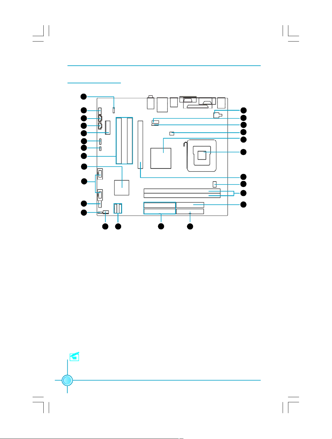
Motherboard Layout
1
Chapter 1 Product Introduction
2
3
4
5
6
7
8
9
10
11
12
13 14
1. S/PDIF OUT Connector
2. Front Audio Connector
3. CD_IN Connector
4. AUX_IN Connector
5.PCI Express X1 slot
6.Speaker Connector
7. Clear CMOS Jumper
8. PCI Slots
9. South Bridge: VIA VT8237R Plus
10. Front USB Connectors
11. Front Panel Connector
12. BIOS Write Protect Jumper
13. System Fan Connector
15
16
14.SATA Connectors
15.HDD Connectors
16.FDD Connector
17.24-pin ATX Power Connector
18.DDR 2 memory Slots
19.CPU Fan Connector
20.PCI Express X16 slot
21.CPU Socket
22.North Bridge: VIA P4M890
23.System Fan Connector
24. IrDA connector
25.COM2 Connector
26.4-pin ATX 12V Power Connector
26
25
24
23
22
21
20
19
18
17
Note: This motherboard layout is provided for reference only; please refer
to the physical motherboard.
4
Page 12
Chapter 1 Product Introduction
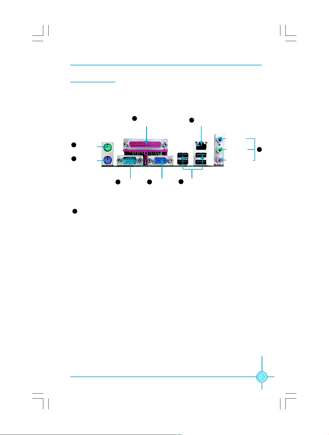
Rear Panel Ports
This motherboard provides the ports as below:
Parallel Port
4
(Printer Port)
7
LAN Port
PS/2 Mouse
1
Port
PS/2 Keyboard
2
Port
Serial Port
3
(COM1)
8
Use the three audio ports to connect audio devices. The Line-in jack is for a
VGA Port
5
6
USB 2.0 Ports
Line-in jack
Line-out jack
Microphone jack
tape player or other audio sources. The Line-out jack is for a headphone or a
speaker. The Microphone jack is for a microphone. In 6-Channel mode, the
function of the three jacks becomes Rear Speaker Out, Front Speaker Out and
Center/Subwoofer Speaker respectively.
8
5
Page 13

Chapter 2 Installation Instructions
Chapter
2
2
This chapter introduces the hardware installation process,
including the installation of the CPU and memory. It also
addresses the connection of your power supply, connection of hard drive and floppy drive data cables, and setting
up various other feature of the motherboard. Caution
should be exercised during the installation process.
Please refer to the motherboard layout prior to any
installation and read the contents in this chapter
carefully.
This chapter includes the following information:
v CPU
v Memory
v Power Supply
v Other Connectors
v Expansion Slots
v Jumpers
6
Page 14

Chapter 2 Installation Instructions
CPU
This motherboard supports Intel® Pentium® 4 Extreme Edition,Pentium® D,
Pentium® 4, Celeron® D processor in an LGA775 package.
For the detailed CPU support list on this motherboard, please visit the
website: http://w w w.fo xconn channel.com
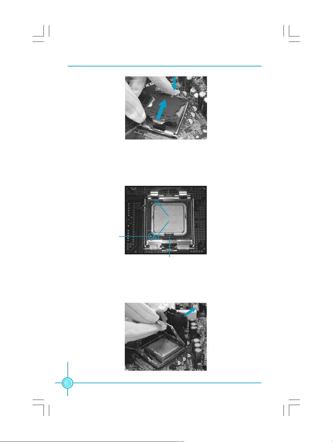
Installation of CPU
Below is the CPU socket illustration. Follow these procedures to install a CPU.
Load lever
1. Use thumb and forefinger to hold the hook of the load lever and pull the lever
down and away from socket to unlock it. Lift the load lever.
2. Push down the rear tab with your forefinger to bring the front end of the load
plate up slightly. Open the load plate with thumb. Be careful not to touch the
contacts.
Load plate
Protective cover
7
Page 15
Chapter 2 Installation Instructions
3. Hold CPU with thumb and forefinger. Ensure fingers align to socket cutouts.
Match the CPU triangle marker to Pin 1 position as shown below. The alignment
key also provides the orientation directed function. Lower the CPU straight down
without tilting or sliding the CPU in the socket.
Alignment Key
Pin 1 position
Socket Cutouts
4. After installing the CPU, remove the protective cover from load plate. The
protective cover is used to protect the contacts of the socket. Do not discard the
protective cover. Always replace the socket cover if the CPU is removed from the
socket.
8
Page 16
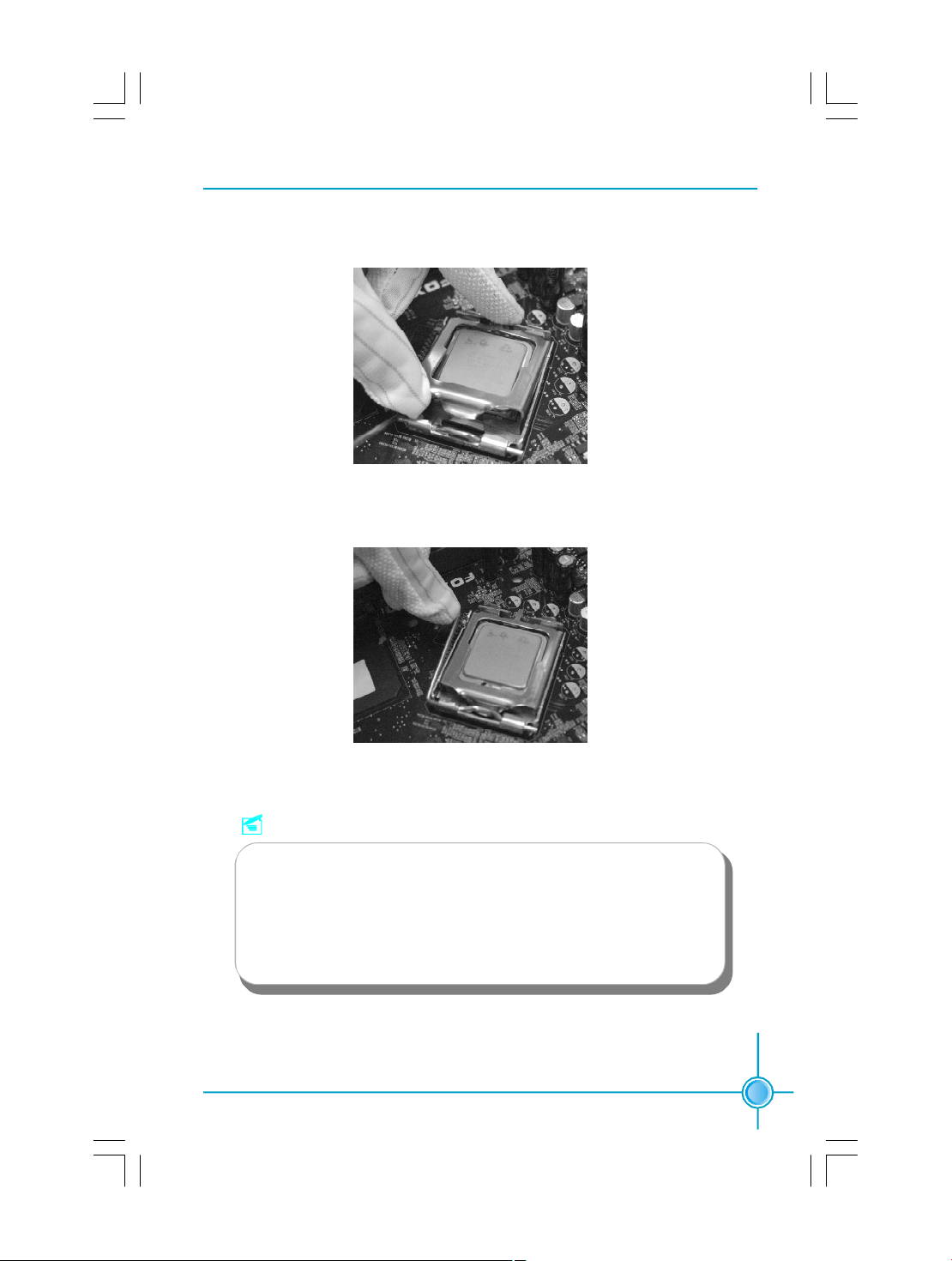
Chapter 2 Installation Instructions
5. Close the load plate, and slightly push down the tongue side.
6. Lower the lever and lock it to the load plate, then the CPU is locked completely.
Note :
Excessive temperatures will severely damage the CPU and
system. Therefore, you should install CPU cooling fan and make
sure that the cooling fan works normally at all times in order to
prevent overheating and damaging to the CPU. Please refer to your
CPU fan user guide to install it properly.
9
Page 17
Chapter 2 Installation Instructions
Memory
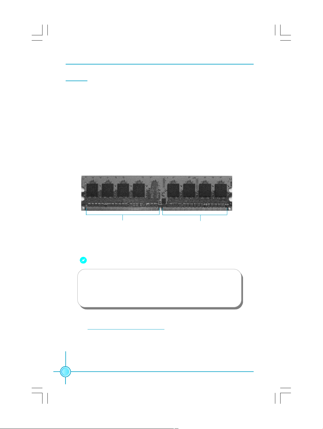
This motherboard includes two 240-pin slots for DDR2. You must install at
least one memory module to ensure normal operation. Mixed memory modules
from different manufacturers is not recommended.
Installation of DDR2 Memory
1.There is only one gap near the center of the DIMM slot, and the memory
module can be fixed in one direction only. Unlock a DIMM slot by pressing the
module clips outward.
2.Align the memory module to the DIMM slot, and insert the module vertically
into the DIMM slot.
128 Pins
3.The plastic clips at both sides of the DIMM slot will lock automatically.
112 Pins
Warning :
Be sure to unplug the AC power supply before adding or removing
expansion cards or other system peripherals, especially the
memory devices, otherwise your motherboard or the system
memory might be seriously damaged.
For the detailed memory support list on this motherboard, please visit the
website: http://w w w.fo xconn channel.com
10
Page 18
Chapter 2 Installation Instructions
Power Supply
This motherboard uses an ATX power supply. In order to avoid damaging any
devices, make sure that they have been installed properly prior to connecting the
power supply.
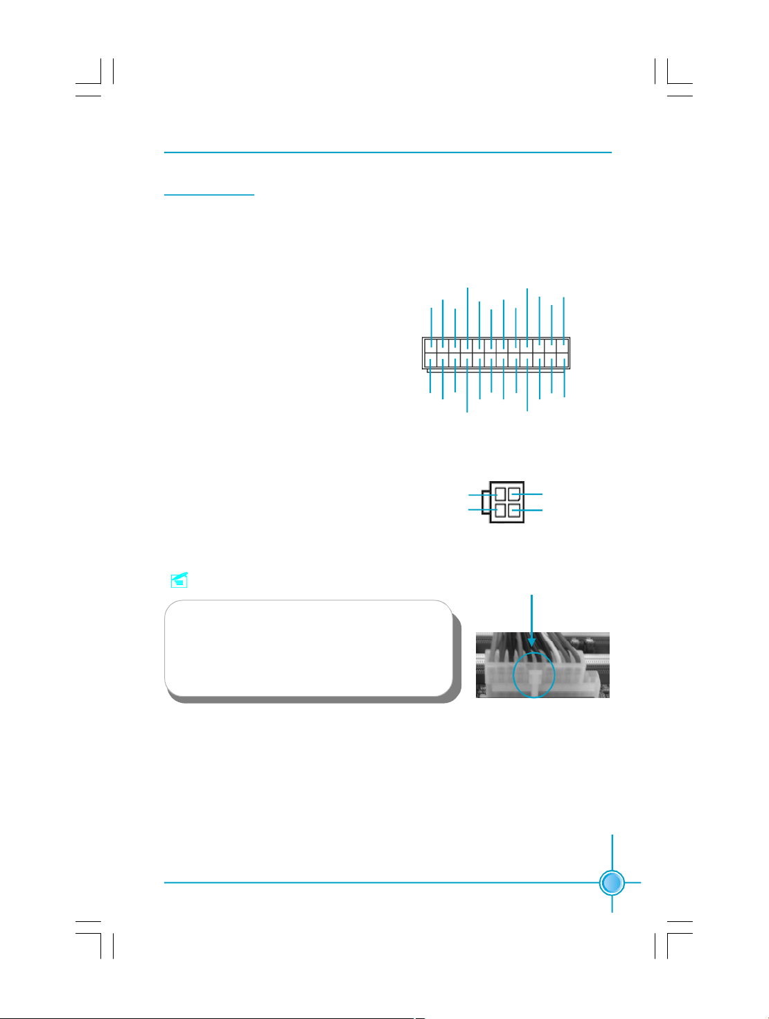
24-pin ATX power connector: PWR1
PWR1 is the ATX power supply connector.
Make sure that the power supply cable
and pins are properly aligned with the
connector on the motherboard. Firmly
plug the power supply cable into the connector and make sure it is secure.
24-pin ATX Power Connector
+5V
+3.3V
GND
GND GND
-12V
PSON
GND
GND
+3.3V
1
+3.3V
+5V_AUX
+3.3V
+12V
GND
+5V
GND
PWROK
NC
+5V
+5V
+12V
+5V
12
2413
GND
4-pin ATX_12V Power Connector: PWR2
The ATX power supply connects to PWR2
and provides power to the CPU.
Note:
We recommend that you use 300 W power
supply or above. If you want to use 20-pin power
supply, you need to align the ATX power connector according to the right picture.
4-pin ATX-12V Power Connector
12V
12V
3 1
4 2
GND
GND
Align the connector
11
Page 19
Chapter 2 Installation Instructions
Other Connectors
This motherboard includes connectors for FDD devices, IDE devices, Serial ATA
devices, USB devices, IR module, and others.
FDD Connector: FLOPPY
This motherboard includes a standard FDD connector, supporting 360K, 720K,
1.2M, 1.44M, and 2.88M FDDs.
HDD Connectors: PIDE & SIDE
This connectors support the provided Ultra DMA 133/100/66 IDE hard disk
ribbon cable. Connect the cable’s blue connector to the primary (recommended)
or secondary IDE connector, then connect the gray connector to the Ultra DMA
133/100/66 slave device (hard disk drive) and the black connector to the Ultra
DMA 133/100/66 master device.
Attention:
Ribbon cables are directional, therefore, make sure to
always connect with the cable on the same side as pin 1 of the
PIDE/SIDE or FDD connector on the motherboard.
COM2 Connector: COM2
This connector accommodates a second serial port using an optional serial port
bracket. Connect the bracket cable to this connector then install the bracket into
a slot opening at the back of the system chassis.
2
1
RLSD
SOUT
GND
RTS
RI
9
COM2
SIN
DTR
DSR
CTS
NA
10
12
Page 20

Chapter 2 Installation Instructions
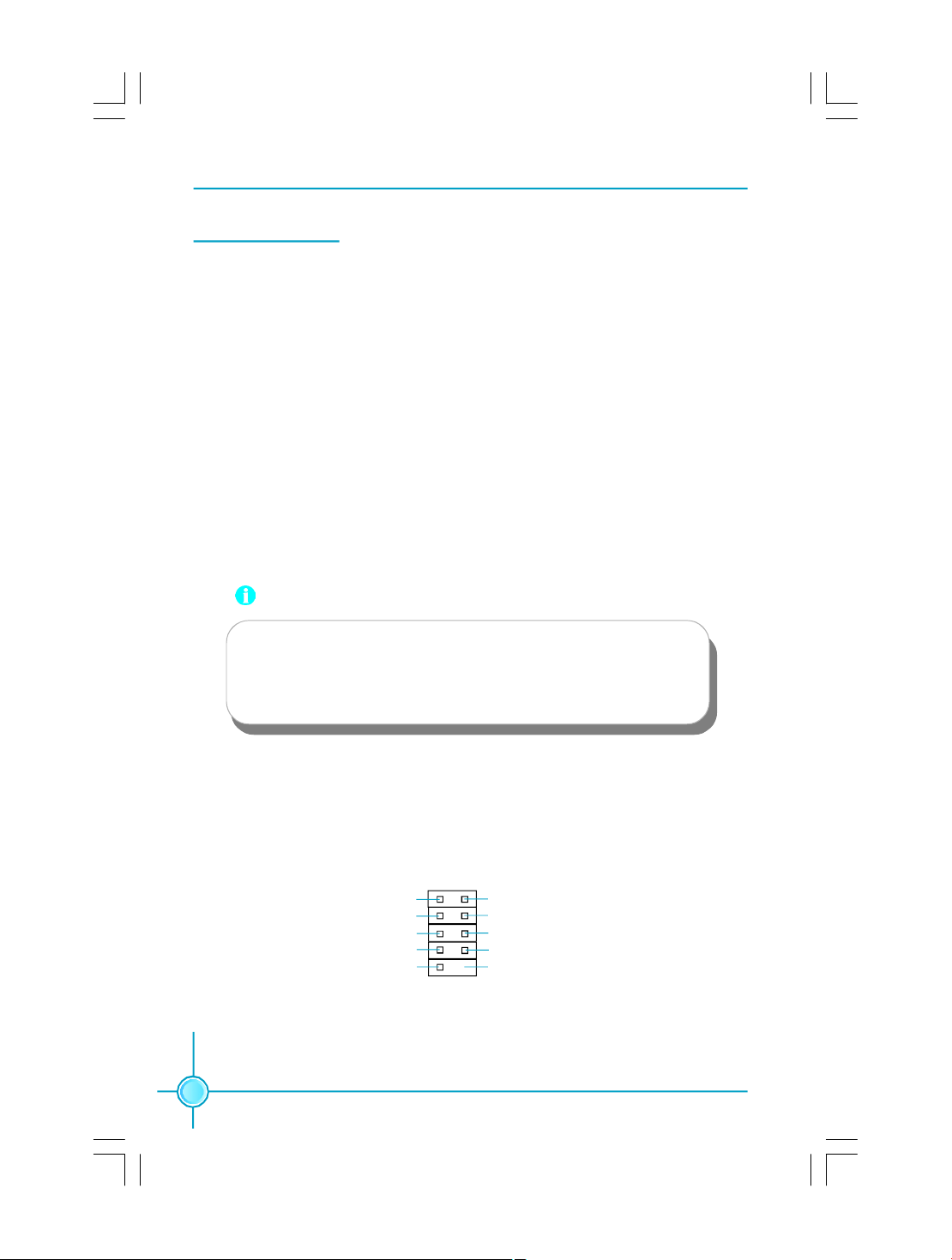
Front Panel Connector: FP1
This motherboard includes one connector for connecting the front panel switch
and LED indicators.
FP1
Hard Disk LED Connector (HDD_LED)
The connector connects to the case’s IDE indicator LED indicating the activity
status of IDE hard disk.
Reset Switch (RESET)
Attach the connector to the Reset switch on the front panel of the case; the
system will restart when the switch is pressed.
Power LED Connector (PLED)
Attach the connector to the power LED on the front panel of the case. The Power
LED indicates the system’s status. When the system is in S0 status, the LED is
on. When the system is in S1 status, the LED is blink; When the system is in S3,
S4, S5 status, the LED is off.
Power Swith Connector (PWRBTN#)
Attach the connector to the power button of the case. Pushing this switch allows
the system to be turned on and off rather than using the power supply button.
PLEDPWRBTN#
+ -
1 + -
NCHDD_LEDRESET
Front Audio Connector: F_AUDIO
The audio connector provides two kinds of audio output choices: the Front Audio,
the Rear Audio. Their priority is sequenced from high to low (Front Audio to Rear
Audio). If headphones are plugged into the front panel of the chassis (using the
Front Audio), then the Line-out (Rear Audio) on the rear panel will not work. If you
do not want to use the Front Audio, pin 5 and 6, pin9 and 10 must be short, and
then the signal will be sent to the rear audio port.
MIC_IN
MIC_PWR
AUD_OUT_R
NA
AUD_OUT_L
21
9
10
F_AUDIO
MIC_GND
+5VA
AUD_RET_R
Empty
AUD_RET_L
13
Page 21

Chapter 2 Installation Instructions
IrDA Connector: IR
This connector supports wireless transmitting
and receiving device. Before using this function,
configure the settings of IR Address, IR Mode
and IR IRQ from the “Integrated Peripherals”
section of the CMOS Setup.
1
+5V
Empty
RX
GND
TX
IR
USB Connectors: F_USB1, F_USB2
Besides four USB ports on the rear panel, the
series of motherboards also have two 10-pin
header on board which may connect to front
panel USB cable to provide additional four USB
ports.
Fan Connectors: CPU_FAN, SYS_FAN
The speed of CPU_FAN and SYS_FAN can be
detected and viewed in “PC Health Status” sec-
tion of the CMOS Setup. These fans will be automatically turned off after the system enters
suspend mode.
Audio Connectors: CD_IN, AUX_IN
CD_IN and AUX_IN are Sony standard CD audio connectors, they can be connected to a CDROM drive through a CD audio cable.
VCC
D-
D+
GND
Empty
F_USB1/2
1
CPU_FAN
GND
1
1
1
+12V
SENSE
CD_R
GND
CD_L
AUX_R
GND
AUX_L
VCC
DD+
GND
NC
CONTROL
SENSE
POWER
GND
SYS_FAN
CD_IN
AUX_IN
14
Page 22

Chapter 2 Installation Instructions
S/PDIF Out Connector: SPDIF_OUT
The S/PDIF out connector is capable of providing digital audio to external speakers or compressed AC3 data to an external Dolby digital
decoder.
Note:The empty pin of S/PDIF cable should be
aligned to empty pin of S/PDIF out connector.
Speaker Connector: SPEAKER
The speaker connector is used to connect
speaker of the chassis.
Serial ATA Connectors: SATA_1, SATA_2
The Serial ATA connectors are used to connect
the Serial ATA devices to the motherboard.
These connectors support the thin Serial ATA
cables for primary storage devices. The current
Serial ATA interface allows up to 150MB/s data
transfer rate.
These two serial ATA connectors support RAID
0, RAID 1, JBOD configuration.
+5V
1
Empty
SPDIF_OUT
GND
SPDIF_OUT
1
SPEAKER
1
GND GND
GND
RX+
TX+
RX-TX-
SATA_1/2
SPK (Pull high)
Empty
NC
SPKJ
15
Page 23

Chapter 2 Installation Instructions
Expansion Slots
This motherboard includes two 32-bit master PCI slots, one PCI Express x 1
slot, and one PCI Express x 16 slot.
PCI Slots
The expansion cards can be installed in the two PCI slots. PCI slots support
cards such as a LAN card, USB card, SCSI card and other cards that comply
with PCI specifications.
PCI Express x1 Slot
This motherboard has one PCI Express x1 slot that designed to accommodate
less bandwidth-intensive cards, such as a modem or LAN card.
PCI Express x16 Slot
This motherboard has one PCI Express x16 slot that reserved for graphics or
video cards. The difference in bandwidth between the x16 and x1 slot is notable
to be sure.
For the detailed PCI Express x16 graphics card supports list on this
motherboard, please visit the website: http://w w w .fo xco n n c h an n el.com
Installing an expansion card
1.Before installing the expansion card, read carefully the documentation that
came withit and make the necessary hardware settings for the card.
2.Make sure to unplug the power card before adding or removing any expansion cards.
3.Remove the bracket opposite the slot that you intend to use.
4.Align the card connector with the slot and press firmly until the card is
completely seated in the slot.
5.Secure the card to the chassis with the screw you removed earlier.
16
Page 24

Chapter 2 Installation Instructions
Jumpers
The users can change the jumper settings on this motherboard if needed. This section explains how to use the various functions of this motherboard by changing the
jumper settings. Users should read the following contents carefully prior to modifying
any jumper settings.
Description of Jumpers
1. For the jumpers on this motherboard, pin 1 can be identified by the bold
silk-screen printed next to it. However, in this manual, pin 1 is simply
labeled as “1”.
2. The following table provides some explanation of the jumper pin settings.
User should refer to this when adjusting jumper settings.
Jumper Diagram Definition Description
1
2-3 Set pin2 and pin3 closed
1
1
1
1
1
Clear CMOS Jumper: CLS_CMOS
This motherboard uses the CMOS RAM to store all
the set parameters. The CMOS can be cleared by
removing the CMOS jumper.
How to clear CMOS?
1.Turn off the AC power supply and quickly
connect pins 1 and 2 together using the
jumper cap.
2.Return the jumper setting to normal (pins 2
and 3 locked together with the jumper cap).
3.Turn the AC power supply back on.
1-2 Set pin1 and pin2 closed
Closed Set the pin closed
Open Set the pin opened
Normal Status
(Default)
Clear CMOS
Clear CMOS Jumper
3
1
2
3
2
1
Warning:
1. Disconnect the power cable before adjusting the jumper settings.
2. Do not clear the CMOS while the system is turned on.
17
Page 25

Chapter 2 Installation Instructions
BIOS protection Jumper: WP_EN (optional)
If the jumper WP_EN is set as OPEN, the system
BIOS is protected from being attacked by a serious
virus, such as the CIH virus. You will be unable to
flash the BIOS to the motherboard, when the system BIOS is protected.
CLOSED
Disabled
OPEN
Enabled
3
2
1
3
2
1
WP_EN
18
Page 26

Chapter 3 BIOS Description
Chapter
This chapter tells how to change system settings through the
BIOS Setup menus. Detailed descriptions of the BIOS parameters are also provided.
You have to run the Setup Program when the following cases
occur:
1.An error message appears on the screen during the system
POST process.
2.You want to change the default CMOS settings.
This chapter includes the following information:
v FOX Central Control Unit
3
3
v Enter BIOS Setup
v Main Menu
v Standard CMOS Features
v Advanced BIOS Features
v Advanced Chipset Features
v Integrated Peripherals
v Power Management Setup
v PnP/PCI Configurations
v PC Health Status
v Load Fail-Safe Defaults
v Load Optimized Defaults
v Set Supervisor/User Password
v Save & Exit Setup
v Exit Without Saving
19
Page 27

Chapter 3 BIOS Description
Enter BIOS Setup
The BIOS is the communication bridge between hardware and software,
correctly setting up the BIOS parameters is critical to maintain optimal system
performance. Power on the computer, when the following message briefly
appears at the bottom of the screen during the POST (Power On Self Test),
press <Del> key to enter the Award BIOS CMOS Setup Utility.
Press TAB to show POST Screen, DEL to enter SETUP.
Note:
We do not suggest that you change the default parameters in the
BIOS Setup, and we shall not be responsible for any damage that
result from any changes that you make.
Main Menu
The main menu allows you to select from the list of setup functions and two exit
choices. Use the arrow keys to select among the items and press <Enter> to
accept or go to the sub-menu.
Main Menu
The items in the main menu are explained as below:
Standard CMOS Features
The basic system configuration can be set up through this menu.
FOX Central Control Unit
The special features can be set up through this menu.
20
Page 28

Chapter 3 BIOS Description
Advanced BIOS Features
The advanced system features can be set up through this menu.
Advanced Chipset Features
The values for the chipset can be changed through this menu, and the system performance can be optimized.
Integrated Peripherals
All onboard peripherals can be set up through this menu.
Power Management Setup
All the items of Green function features can be set up through this menu.
PnP/PCI Configurations
The system’s PnP/PCI settings and parameters can be modified through
this menu.
PC Health Status
This will display the current status of your PC.
Load Fail-Safe Defaults
The default BIOS settings can be loaded through this menu.
Load Optimized Defaults
The optimal performance settings can be loaded through this menu,
however, the stable default values may be affected.
Set Supervisor Password
The supervisor password can be set up through this menu.
Set User Password
The user password can be set up through this menu.
Save & Exit Setup
Save CMOS value settings to CMOS and exit setup.
Exit Without Saving
Abandon all CMOS value changes and exit setup.
21
Page 29

Chapter 3 BIOS Description
Standard CMOS Features
This sub-menu is used to set up the standard CMOS features, such as the date,
time, HDD model and so on. Use the arrow keys select the item to set up, and
then use the <PgUp> or <PgDn> keys to choose the setting values.
Standard CMOS Features Menu
Date
This option allows you to set the desired date (usually as the current day) with
the <day><month><date><year> format.
Day—weekday from Sun. to Sat., defined by BIOS (read-only).
Month—month from Jan. to Dec..
Date—date from 1st to 31st, can be changed using the keyboard.
Year—year, set up by users.
Time
This option allows you to set up the desired time (usually as the current time)
with <hour><minute><second> format.
IDE Channel 0/1 Master/Slave, IDE Channel 2/3 Master
These categories identify the HDD types of 2 IDE channels installed in the
computer system. There are three choices provided for the Enhanced IDE BIOS:
None, Auto, and Manual. “None” means no HDD is installed or set; “Auto” means
the system can auto-detect the hard disk when booting up; by choosing “Manual”
and changing Access Mode to “CHS”, the related information should be entered
manually. Enter the information directly from the keyboard and press < Enter>:
Cylinder number of cylinders Head number of heads
Precomp write pre-compensationLanding Zone landing zone
Sector number of sectors
22
Page 30

Chapter 3 BIOS Description
Award (Phoenix) BIOS can support 3 HDD modes: CHS, LBA and Large or Auto mode.
CHS For HDD<528MB
LBA For HDD>528MB & supporting LBA (Logical Block Addressing)
Large For HDD>528MB but not supporting LBA
Auto Recommended mode
Drive A
This option allows you to select the kind of FDD to be installed, including “None”,
[360K, 5.25 in], [1.2M, 5.25 in], [720K, 3.5 in], [1.44M, 3.5 in] and [2.88 M, 3.5 in].
Video
The following table is provided for your reference in setting the display mode
for your system.
EGA/VGA Enhanced Graphics Adapter / Video Graphic Array. For
EGA, VGA, SEGA, SVGA, or PGA monitor adapters.
CGA 40 Color Graphic Adapter, powering up in 40 column mode.
CGA 80 Color Graphic Adapter, powering up in 80 column mode.
MONO Monochrome adapter, including high resolution monochrome adapters.
Halt On
This category determines whether or not the computer will stop if an error is
detected during powering up.
All Errors Whenever the BIOS detects a nonfatal error, the system
will stop and you will be prompted.
No Errors The system boot will not stop for any errors that may
be detected.
All, But Keyboard The system boot will not stop for a keyboard error; but
it will stop for all other errors.
All, But Diskette The system boot will not stop for a diskette error; but
it will stop for all other errors.
All, But Disk/Key The system boot will not stop for a keyboard or disk
error, but it will stop for all other errors.
23
Page 31

Chapter 3 BIOS Description
Memory
This is a Display-Only Category, determined by POST (Power On Self Test) of
the BIOS.
Base Memory The BIOS POST will determine the amount of base (or
conventional) memory installed in the system.
Extended Memory The BIOS determines how much extended memory
is present during the POST.
Total Memory Total memory of the system.
24
Page 32

Chapter 3 BIOS Description
FOX Central Control Unit
FOX Central Control Unit Menu
v[Smart BIOS]
Smart Power LED
Smart debug LED function within power LED. Enable this function, the power
LED status can show the system status of POST process.
System Status Power LED Status
Normal on
No CPU Fan blinking once (blinking 0.5 sec., off 0.5 sec.)
No Display blinking once (blinking 2 sec., off 2 sec.)
No Memory blinking twice
Post Error Message blinking thrice
Smart Boot Menu
Smart boot menu with a timer to let user to control boot device easily.
vSmooth Over Clock
To open smooth over clock function can let over clocking to be more stable.
vCPU Clock Ratio
This option is used to set the ratio of an unlocked CPU. Using different CPU
the setting values are different.
vAuto Detect PCI Clk
This option is used to set whether the clock of an unused PCI slot will be
disabled to reduce electromagnetic interference. The setting values are
Disabled and Enabled.
25
Page 33

Chapter 3 BIOS Description
vSpread Spectrum
If you enable spread spectrum, it can significantly reduce the EMI(Electro Magnetic Interference) generated by the system. The setting values are Dis abled and Enabled.
vCPU Clock
This option is used to set the CPU clock.
vDRAM Clock/Driver Control
Press Enter to set the items of DRAM Clock/Driver Control.
26
Page 34

Chapter 3 BIOS Description
DRAM Clock/Drive Control Menu
v1T CMD Support
This option is used to set whether the first command delay of 1 clock cycle
is enable.
vCurrent FSB/DRAM Frequency
This option is used to show current FSB and DRAM Frequency.
vDRAM Clock
This option is used to set DRAM clock.
vDRAM Timing
Selects whether DRAM timing is controlled by the SPD (Serial Presence Detect)
EEPROM on the DRAM module. Setting to “Auto By SPD” enables DRAM timings to be determined by BIOS based on the configurations on the SPD.
Selecting “Manual” allows users to configure the DRAM timings manually.
The setting values are:Manual, Auto By SPD, Turbo, Ultra.
vSDRAM CAS Latency [DDR/DDR2]
When synchronous SDRAM is installed, the number of clock cycles of CAS
latency depends on the SDRAM timing.
vBank Interleave
This field selects 2-bank or 4-bank interleave for the installed SDRAM. Disable the function if 16MB SDRAM is installed.
27
Page 35

Chapter 3 BIOS Description
vPrecharge to Active (Trp)
This option controls the number of cycles for Row Address Strobe (RAS) to
be allowed to precharge. If insufficient time is allowed for the RAS to
accumulate its charge before DRAM refresh, refresh may be incomplete
and DRAM may fail to retain data. This option applies only when synchronous DRAM is installed in the system.
v Active to Precharge(Tras)
This option is used to set active to precharge(Tras).
v Active to CMD<Trcd>
When DRAM is refreshed, both rows and columns are addressed separately.
This setup option allows you to determine the timing of the transition from
RAS (row address strobe) to CAS (column address strobe). The less the
clock cycles, the faster the DRAM performance.
v REF to ACT/REF (Trfc)
This option is used to set REF to ACT/REF (Trfc).
v ACT(0) to ACT(1) (TRRD)
This option is used to set ACT(0) to ACT(1) (TRRD).
28
Page 36

Chapter 3 BIOS Description
Advanced BIOS Features
Advanced BIOS Features Menu
vCPU Feature
Press enter to set the items of CPU feature.
vHard Disk Boot Priority
This option is used to select the priority for HDD startup. After pressing
<Enter>, you can select the HDD using the <PageUp>/<PageDn> or Up/Down
arrow keys, and change the HDD priority using <+> or <->. To exit this option,
press <Esc>.
vVirus Warning
Allows you to choose the VIRUS warning feature for IDE hard disk boot sector
protection. If this function is enabled and someone attempt to write data into
this area, BIOS will show a warning message on screen and an alarm will
beep. The setting values are: Disabled and Enabled.
Note: Such function provides protection to the start-up sector only; it does
not protect the entire hard disk.
vCPU L1 & L2 Cache
This option is used to enable or disable the L1 and L2 CPU cache. The
available setting values are: Disabled and Enabled.
vCPU L2 Cache ECC Checking
This option is used to enable or disable CPU L2 cache ECC Checking. The
setting values are: Disabled and Enabled.
vQuick Power On Self Test
Enable this option to shorten the power on tesing (POST) and have your sys
tem start up faster.
29
Page 37

Chapter 3 BIOS Description
vFirst/Second/Third Boot Device
This option allows you to set the boot device sequence. The available setting
values are: Floppy, LS120, Hard Disk, CDROM, ZIP100, USB-FDD, USB-ZIP,
USB-CDROM, Legacy LAN, NVIDIA Boot Age and Disabled.
vBoot Other Device
With this item enabled, the system will search all other possible locations if it
fails to find one in the devices specified under the first, second and third boot
devices.
vBoot Up Floppy Seek
This option controls shether the BIOS checks for a floppy drive while booting
up. If it cannot detect one (eiter due to improper configuration or physical
unavailability), it will appear an error message. The available setting values
are: Disabled and Enabled.
vBoot Up NumLock Status
This option defines if the keyboard Num Lock key is active when your system
is started. The setting values are: On and Off.
vTypematic Rate Setting
If this option is enabled, you can use the following two items to see the
typematic rate and the typematic delay settings for your keyboard. The available setting values are: Disabled and Enabled.
vTypematic Rate (Chars/Sec)
Use this option to define how many characters per second a held-down
key generated.
vTypematic Delay (Msec)
Use this option to define how many milliseconds must elapse before a helddown key beings generating repeat characters.
vSecurity Option
When it is set to “Setup”, a password is required to enter the CMOS Setup
screen; When it is set to “System”, a password is required not only to enter
CMOS Setup, but also to start up your PC.
vMPS Version Control For OS
This option is used to set up the version of MPS Table used in NT4.0 OS.
30
Page 38

Chapter 3 BIOS Description
vOS Select For DRAM > 64MB
This option is only required if you have installed more than 64 MB of memory
and you are running the OS/2 operating system. Otherwise, leave this option
at the default.
vDelay For HDD(Secs)
This option is used to set delay boot time of HDD controller.
vFull Screen LOGO Show
This option allows you to enable or disable the full screen logo. The available
setting values are: Disabled and Enabled.
vSmall Logo (EPA) Show
This option allows you to enable or disable the EPA logo. The available setting
values are: Disabled and Enabled.
31
Page 39

Chapter 3 BIOS Description
CPU Feature Menu
v Delay Prior to Thermal
This option is used to set the delay time before the CPU enters auto thermal
mode. The setting values are: 4 Min, 8 Min, 16 Min, 32 Min.
vThermal Management
This option is used to manage Prescott CPU thermal.
v TM2 Bus Ratio
Represents the frequency bus ratio of the throttled performance state that will
be initiated when the on-diesensor goes from not hot to hot .
v TM2 Bus VID
Represents the voltage of the throttled performance state that will be initiated
when the on-diesensor goes from not hot to hot.
vLimit CPUID MaxVal
The option is used to set limit CPUID MaxVal. The available setting values are:
Disabled and Enabled. Set Limit CPUID MaxVal to 3, should be "Disabled" for
WinXP.
vExecute Disable Bit
The option is used to enable or disable execute disable bit.
32
Page 40

Chapter 3 BIOS Description
Advanced Chipset Features
Advanced Chipset Features Menu
vAGP & P2P Bridge Control
Press enter to set the items about AGP & P2P bridge.
vCPU & PCI Bus Control
Press enter to set the items about CPU & PCI bus.
vMemory Hole
This option is used to select memory hole. The setting values are: Disabled,
15M-16M.
vSystem BIOS Cacheable
Select “Enabled” to allow caching of the system BIOS which may improve
performance. If any other program writes to this memory area, a system error
may result. The available setting values are: Enabled and Disabled.
vTop Performance
This option is used to set overclock performance.
33
Page 41

Chapter 3 BIOS Description
AGP & P2P Bridge Control Menu
vAGP Aperture Size
This option defines the size of the aperture if you use an AGP graphics adapter.
The aperture is a portion of the PCI memory address range dedicated for
graphic memory address space.
Note: This function does not work when onboard VGA is used.
vAGP 3.0 Mode
This option is used to set an appropriate mode for the installed AGP card.
vAGP Master 1 WS Write
When “Enabled”, writes to the AGP (Accelerated Graphics Port) are executed
with one wait states. The setting values are: Disabled and Enabled.
vAGP Master 1 WS Read
When “Enabled”, reads to the AGP (Accelerated Graphics Port) are executed
with one wait states. The setting values are: Disabled and Enabled.
vVGA Share Memory Size
This option is used to set the onboard VGA share memory size. If you are
running under Windows XP or Windows 2000, set this option to 32M or lower.
The setting values are: Disabled, 16M, 32M, 64M.
vDirect Frame Buffer
This option is used to enable or disable direct frame buffer.
34
Page 42

Chapter 3 BIOS Description
CPU & PCI Bus Control Menu
vPCI Master 0 WS Write
This option allows you to enable or disable the support of PCI Master 0 Wait
State Write. The setting values are: Disabled and Enabled.
vPCI Delay Transaction
This option allows you to enable or disable PCI delay transaction. The setting
value are: Disabled and Enabled.
vVLink mode selection
This option allows you to select VLink mode.
vVLink 8X Support
This option allows you to enable or disable the VLink 8X support. When
“Enabled”, it may increase system performance. The setting values are:
Disabled and Enabled.
vVIA PWR Management
This option is used to manage the power supply of VIA.
35
Page 43

Chapter 3 BIOS Description
Integrated Peripherals
Integrated Peripherals Menu
vVIA OnChip IDE Device
Press enter to set onchip IDE device.
vVIA OnChip PCI Device
Press enter to set onchip PCI device.
vSuperIO Device
Press enter to set onboard SuperIO device.
vOnboard Lan Device
This option is used to enable or disable onboard LAN device.
vOnboard Lan Boot ROM
The option enables or disables the initialization of the onboard LAN Boot
ROM during bootup.
36
Page 44

Chapter 3 BIOS Description
VIA OnChip IDE Device Menu
v OnChip SATA
This option is used to enable or disable onchip SATA. The setting values are:
Disabled and Enabled.
vSATA Mode
This option is used to select SATA mode. The settingvalues are: IDE and
RAID.
vIDE DMA transfer access
This option is used to enable or disable IDE DMA transfer access. The setting
values are: Disabled and Enabled.
vOnChip IDE Channel 0/1
The integrated peripheral controller contains an IDE interface with support for
two IDE channels. Choose “Enabled” to activate each channel separately.
The setting values are: Disabled and Enabled.
vIDE Prefetch Mode
This option is used to enable or disable IDE prefetch mode. The setting
values are: Disabled and Enabled.
vPrimary/Secondary Master/Salve PIO
These four items let you assign which kind of PIO (Programmed Input/Output)
is used by IDE devices. Choose Auto to let the system auto detect which PIO
mode is best or select a PIO mode from 0-4.
vPrimary/Secondary Master/Salve UDMA
UltraDMA technology provides faster access to IDE devices. If you install a
device that supports UltraDMA, change the appropriate item on this list to
Auto. The available setting values are: Disabled and Auto.
vIDE HDD Block Mode
This option is used to set whether the IDE HDD Block Mode is allowed. The
available setting values are: Disabled and Enabled.
37
Page 45

Chapter 3 BIOS Description
VIA OnChip PCI Device Menu
vVIA-3058 AC97 Audio
“Auto” allows the motherboard’s BIOS to detect whether you’re using any
audio devices. If so, the onboard audio controller will be enabled. If not, the
onboard audio controller will be disabled. If you want to use different controller cards to connect audio connectors, set the option to “Disabled”. The setting values are: Disabled and Auto.
vOnChip USB Controller
This option is used to set onchip USB controller.
vOnChip EHCI Controller
This option is used to enable or disable onchip EHCI controller. The setting
values are: Disabled and Enabled.
vUSB Emulation
This option is used to enable or disable USB legacy keyboard, mouse, and
USB storage.
vUSB Keyboard/Mouse Support
When USB Emulation is set as KM/MS, the two options are for choosing. This
option is used to enable or disable USB keyboard/mouse support. The
setting values are: Disabled and Enabled.
38
Page 46

Chapter 3 BIOS Description
SuperIO Device Menu
vOnboard FDC Controller
This option is used to set whether the Onboard FDC Controller is enabled.
The available setting values are: Disabled and Enabled.
vOnboard Serial Port1/2
This option is used to assign the I/O address and interrupt request (IRQ) for
the onboard serial port 1/2.
Note: Do not try to set the same values for serial ports 1 and 2.
vUART Mode Select
Use this option to select the UART mode. Setting values include Normal,
IrDA, and ASKIR. The setting value is determined by the infrared module in
stalled on the board.
vUR2 Duplex Mode
This option is available when UART 2 mode is set to either ASKIR or IrDA. This
item enables you to determine the infrared function of the onboard infrared chip.
vOnboard Parallel Port
This option allows you to determine onboard parallel port controller I/O address and interrupt request (IRQ). The setting values are: Disabled, 378/IRQ7,
278/IRQ5 and 3BC/IRQ7.
vParallel Port Mode
Select an address and corresponding interrupt for the onboard parallel port.
The setting values are: SPP, EPP, ECP, ECP+EPP.
vECP Mode Use DMA
When the Parallel Port Mode is set to ECP or ECP+ EPP, this option is used to
select the channel for the ECP mode. The setting values are: 1 and 3.
39
Page 47

Chapter 3 BIOS Description
Power Management Setup
Power Management Setup Menu
vACPI function
ACPI stands for “Advanced Configuration and Power Interface”. ACPI is a
standard that defines power and configuration management interfaces between an operating system and the BIOS. In other words, it is a standard that
describes how computer components work together to manage system
hardware. In order to use this function the ACPI specification must be supported by the OS (for example, Windows2000 or WindowsXP). The available
setting values are: Enabled and Disabled.
v ACPI Suspend Type
This option is used to set the energy saving mode of the ACPI function.
When you select “S1 (POS)” mode, the power will not shut off and the
supply status will remain as it is, in S1 mode the computer can beresumed
at any time. When you select “S3 (STR)” mode, the power will be cut off after
a delay period. The status of the computer before it enters STR will be saved
in memory, and the computer can quickly return to previous status when the
STR function wakes. When you select “S1 & S3” mode, the system will
automatically select the delay time.
vPower Management Option
This option is used to set the power management scheme. The available
settings are: User Define, Min Saving and Max Saving.
vHDD Power Down
This option is used to define the continuous HDD idle time before the HDD
enters power saving mode. The setting values are: Disabled, 1 Min, 2 Min, 3
Min, 4 Min, 5 Min, 6 Min, 7 Min, 8 Min, 9 Min, 10 Min, 11 Min, 12 Min, 13 Min, 14
Min, 15 Min.
40
Page 48

Chapter 3 BIOS Description
vSuspend Mode
This option is used to set the idle time before the system enters into sleep
status. The setting values are: Disabled, 1 Min, 2 Min, 4 Min, 6 Min, 8 Min, 12
Min, 20 Min, 30 Min, 40 Min, 1 Hour.
vVideo Off Option
This option is used to set video off option. The setting values are: Always On,
Suspend -> Off.
vVideo Off Method
This option is used to define the video off method. “Blank Screen” mode
means that after the computer enters into power saving mode, only the monitor
will close, however, the vertical and horizontal scanning movement of the screen
continues. When you select the “V/H SYNC + Blank” mode the vertical and horizontal scanning movement of screen stops when the computer enters power
saving mode. “DPMS Support” mode is a new screen power management
system, and it needs to be supported by the monitor you’re using.
vMODEM Use IRQ
This option is used to set the IRQ in which the modem can use. The setting
values are: NA, 3, 4, 5, 7, 9, 10, 11.
vSoft-Off by PWRBTN
This option is used to set the power down method. This function is only valid
for systems using an ATX power supply.
When “Instant-Off” is selected, press the power switch to immediately turn
off power.
When “Delay 4 Sec” is selected, press and hold the power button for four
seconds to turn off power.
vRun VGABIOS if S3 Resume
This option allows the system to initialize the VGABIOS from S3 (Suspend to
RAM) sleep state. The available setting values are: Auto, Yes and No.
vAc Loss Auto Restart
The system will switch which status when power comes back after a power
failure. The setting values are: Auto, On, Off.
v IRQ/Event Activity Detect
Press Enter to set IRQ/Event Activity Detect.
41
Page 49

Chapter 3 BIOS Description
IRQ/Event Activity Detect Menu
vPS2KB Wakeup Select
This option is used to select which action will wake up PS/2 keyboard from S3
/S4/S5 staus. Use <PgUp> or <PgDn> to select the desired item.
vPS2KB Wakeup from S3/S4/S5
This option is used to select which hotkey will wake up by PS/2 keyboard from
S3/S4/S5 staus or disable it.
vPS2MS Wakeup from S3/S4/S5
This option is used to enable or disable the system to be waken up by PS/2
mouse from S3/S4/S5 staus.
vUSB Resume from S3
This option is used to enable or disable the USB to be resume from S3.
vVGA
When on of VGA, any activity from one of the listed system peripheral
devices or IRQs wakes up the system.
vLPT & COM
When on of LPT & COM, any activity from one of the listed system peripheral
devices or IRQs wakes up the system. If select “NONE”, cannot wake up the
system.
vHDD & FDD
When on of HDD & FDD, any activity from one of the listed system peripheral
devices or IRQs wakes up the system.
vPCI Master
When on of PCI master, any activity from one of the listed system peripheral
devices or IRQs wakes up the system.
vWakeup on PCI Express
This option is used to set whether the system is wakeuped by PCI Express.
42
Page 50

Chapter 3 BIOS Description
vPowerOn by PCI Card
This option is used to set whether the system is wakeuped by PCI Card.If
“Enabled” any PCI interrupt will wake up the system.
vModem Ring Resume
This option is used to set the system to be waked up by the modem ring.
vRTC Alarm Resume
This option is used to set alarm to power on the system by the date (1-31) or
time (hh:mm:ss).
vDate (of Month)
This option is used to set the timing for the start-up day of the month. The setting
values contain 0 – 31.
vResume Time (hh:mm:ss)
This option is used to set the timing for the start-up time. The setting values
contain hh:0 – 23; mm:0 – 59; ss:0 – 59.
vIRQs Activity Monitoring
Press enter to set the items of IRQs activity monitoring.
43
Page 51

Chapter 3 BIOS Description
IRQs Activity Monitoring Menu
v Primary INTR
Selecting “ON” will cause the system to wake up from power saving modes
if activity is detected from any enabled IRQ channels. The setting values
are: ON and OFF.
vIRQ3 (COM2)
This option is used to enable or disable IRQ3 (COM2) activity monitoring. The
setting value are:Disabled and Enabled.
vIRQ4 (COM1)
This option is used to enable or disable IRQ4 (COM1) activity monitoring. The
setting value are:Disabled and Enabled.
vIRQ5 (LPT2)
This option is used to enable or disable IRQ5 (LPT2) activity monitoring. The
setting value are:Disabled and Enabled.
vIRQ6 (Floppy Disk)
This option is used to enable or disable IRQ6 (Floppy Disk) activity monitoring.
The setting values are: Disabled and Enabled.
vIRQ7 (LPT1)
This option is used to enable or disable IRQ7 (LPT1) activity monitoring. The
setting value are:Disabled and Enabled.
vIRQ8 (RTC Alarm)
This option is used to enable or disable IRQ8 (RTC Alarm) activity monitoring.
The setting values are: Disabled and Enabled.
vIRQ9 (IRQ2 Redir)
This option is used to enable or disable IRQ9 (IRQ2 Redir) activity monitoring.
The setting values are: Disabled and Enabled.
vIRQ10 (Reserved)
This option is used to enable or disable IRQ10 (Reserved) activity monitoring.
The setting values are: Disabled and Enabled.
44
Page 52

Chapter 3 BIOS Description
vIRQ11 (Reserved)
This option is used to enable or disable IRQ11 (Reserved) activity monitoring.
The setting values are: Disabled and Enabled.
vIRQ12 (PS/2 Mouse)
This option is used to enable or disable IRQ12 (PS/2 Mouse) activity monitoring.
The setting values are: Disabled and Enabled.
vIRQ13 (Coprocessor)
This option is used to enable or disable IRQ13 (Coprocessor) activity
monitoring. The setting values are: Disabled and Enabled.
vIRQ14 (Hard Disk)
This option is used to enable or disable IRQ14 (Hard Disk) activity monitoring.
The setting values are: Disabled and Enabled.
vIRQ15 (Reserved)
This option is used to enable or disable IRQ15 (Reserved) activity monitoring.
The setting values are: Disabled and Enabled.
45
Page 53

Chapter 3 BIOS Description
PnP/PCI Configurations
PnP/PCI Configurations Menu
v PNP OS Installed
Set this field to “Yes” if you are running Windows 95, which is PnP compatible.
It is recommended to keep the default setting.
vInit Display First
This option is used to set which display device will be used first when your PC
starts up.
v Reset Configuration Data
This option is used to set whether the system is permitted to automatically
distribute IRQ DMA and I/O addresses when each time that the machine is
turned on. The setting values are: Disabled and Enabled.
vResources Controlled By
This option is used to define the system resource control scheme. If all cards
you use support PnP, then select Auto (ESCD) and the BIOS automatically
distributes interruption resources. If you install ISA cards not supporting PnP,
you will need to select “Manual” and manually adjust interruption resources in
the event of hardware conflicts. However, since this motherboard has no ISA
slot, this option does not apply.
vIRQ Resources
Press the <Enter> key, then manually set IRQ resources.
vPCI/VGA Palette Snoop
If you use a non-standard VGA card, use this option to solve graphic acceleration card or MPEG audio card problems (e.g., colors not accurately displayed).
The setting values are: Disabled and Enabled.
vAssign IRQ For VGA
This option is used to set whether BIOS will assign IRQ for VGA.
46
Page 54

Chapter 3 BIOS Description
vAssign IRQ For USB
This option is used to set whether BIOS will assign IRQ for USB.
vMaximum Payload Size
This option is used to set maximum TLP payload size for PCI Express devices.
The unit is byte.
47
Page 55

Chapter 3 BIOS Description
PC Health Status
PC Health Status Menu
vCPU Warning Temperature
This option is used to set the warning temperature for the system.When the
temperature of CPU is higher than setting value, the motherboard will send
out warning information.
vVcore/ +3.3V/+5V/+12V/5VSB(V)
Display current voltage value including all significant voltages of the mainboard
+3.3V, +5V, +12V are voltages from the power supply.
vVoltage Battery
This option is used to show the voltage of battery.
vCurrent System/CPU Temperature
The current system/CPU temperature will be automatically detected by the
system.
vCurrent SYSTEM/CPU FAN Speed
The current speed of System/CPU fan automatically detected by the system/
CPU.
vSmart FAN Control
This option is used to enable or disable smart fan function.
48
Page 56

Chapter 3 BIOS Description
Load Fail-Safe Defaults
Press <Enter> to select this option. A dialogue box will pop up that allows you to
load the default BIOS settings. Select <Y> and then press <Enter> to load the
defaults. Select <N> and press <Enter> to exit without loading. The defaults set by
BIOS set the basic system functions in order to ensure system stability. But if
your computer cannot POST properly, you should load the fail-safe defaults to
restore the original settings. Then carry out failure testing. If you only want to
load the defaults for a single option, you can select the desired option and
press the <F6> key.
Load Optimized Defaults
Select this option and press <Enter>, and a dialogue box will pop up to let you
load the optimized BIOS default settings. Select <Y> and then press <Enter> to
load the optimized defaults. Select <N> and press <Enter> to exit without loading.
The defaults set by BIOS are the optimized performance parameters for the
system, to improve the performance of your system components. However, if
the optimized performance parameters are not supported by your hardware
devices, it will likely cause system reliability and stability issues. If you only want
to load the optimized default for a single option, select the desired option and
press the <F7> key.
Set Supervisor/User Password
The access rights and permissions associated with the Supervisor password are
higher than those of a regular User password. The Supervisor password can be
used to start the system or modify the CMOS settings. The User password can
also start the system. While the User password can be used to view the current
CMOS settings, these settings cannot be modified using the User password.
When you select the Set Supervisor/User Password option, the following message
will appear in the center of the screen, which will help you to set the password:
Enter Password:
Enter your password, not exceeding 8 characters, then press <Enter>. The
password you enter will replace any previous password. When prompted, key in
the new password and press <Enter>.
49
Page 57

Chapter 3 BIOS Description
If you do not want to set a password, just press <Enter> when prompted to enter
a password, and in the screen the following message will appear. If no password
is keyed in, any user can enter the system and view/modify the CMOS settings.
Password Disabled!!!
Press any key to continue …
Under the menu “Advanced BIOS Features”, if you select “ System” from the
Security Option, you will be prompted to enter a password once the system is
started or whenever you want to enter the CMOS setting program. If the incorrect
password is entered, you will not be permitted to continue.
Under the menu “Advanced BIOS Features”, if you select “Setup” from the Security Option, you will be prompted to enter a password only when you enter the
CMOS setting program.
Save & Exit Setup
When you select this option and press <Enter>, the following message will
appear in the center of the screen:
SAVE to CMOS and EXIT (Y/N)?Y
Press <Y> to save your changes in CMOS and exit the program; press <N> or
<ESC> to return to the main menu.
Exit Without Saving
If you select this option and press <Enter>, the following message will appear
in the center of the screen:
Quit Without Saving (Y/N)?N
Press <Y> to exit CMOS without saving your modifications; press <N> or <ESC>
to return to the main menu.
50
Page 58

Chapter 4 Driver CD Introduction
Chapter
4
4
The utility CD that came with the motherboard contains useful software and several utility drivers that enhance the
motherboard features.
This chapter includes the following information:
v Utility CD content
v Installing Drivers
v Installing Utilities
51
Page 59

Chapter 4 Driver CD Introduction
Utility CD content
This motherboard comes with one Utility CD. To begin using the CD, simply
insert the CD into your CD-ROM drive. The CD will automatically displays the
main menu screen.
1. Install Driver
Using this choice, you can install all the drivers for your motherboard. You should
install the drivers in order and you need to restart your computer after the drivers
all installed.
A.VIA Chipset Driver B.VIA VGA Driver
C.Realtek Audio Driver D.Realtek LAN Driver
2.Accessories
Use this option to install additional software programs.
A.FOX ONE B. Fox LiveUpdate
C.Microsoft DirectX 9.0 D. Adobe Acrobat Reader
E. Norton Security F. Create RAID Driver Floppy
3. Link to website
Click static Foxconn Logo to visit our homepage.
52
Page 60

Chapter 4 Driver CD Introduction
Installing Divers
There are two ways to install drivers, manual or auto. Click the drivers that you
want to install and begin the setup steps by manual. Or you just click “One Click
Setup” button to install the drivers by auto after install Intel Chipset Driver.
Install by manual
Install by auto
Installing Utilities
You can select the utilities that you want to install and begin the setup steps.
Click here
53
Page 61

Chapter 4 Driver CD Introduction
Chapter
5
5
This chapter will introduce how to use attached software.
This chapter provides the following information:
v FOX ONE
v Fox LiveUpdate
54
Page 62

Chapter 5 Directions for Bundled Software
FOX ONE
FOX ONE is a powerful utility for easily modifying system settings. It also allows
users to monitor various temperature values, voltage values, frequency and fan
speed at any time.
With FOX ONE, you can
-Modify system performance settings, such as bus speeds, CPU voltages,
fan speed, and other system performance options that are supported by the
BIOS
-Monitor hardware temperature, voltage, frequency and fan speed
Supported Operating Systems:
-Windows 2000
-Windows XP (32-bit and 64-bit)
-Windows 2003 (32-bit and 64-bit)
Using FOX ONE:
1. Main Page
Show CPU
Information
Toolbar
Monitor Frequency/Voltage/Fan
speed/Temperature value
Alert Lamp
Switch
Button
Exit
Minimum
Configuration
Homepage
55
Page 63

Chapter 5 Directions for Bundled Software
Toolbar
Use the toolbar to navigate to other pages.
Alert Lamp
When the system is in healthy status, the alert lamp color is green. When the
system is in abnormal status, the alert lamp color is red.
Switch Button
Click this button, it will shorten to below figure. It helps you to minitor your
system healthy status at any time.
Click here to return to
previous status
Exit
Click this button to exit the program.
Minimum
Click this button to minimize the window.
Configuration
Click this button to configurate the parameters for the program. It determines
which items will be shown in shorten mode.
Homepage
Click this button to visit Foxconn motherboard website.
2. CPU Page - CPU Control
This page lets you select and run the FOX ONE developed benchmarks to
determine the current performance level of the system. You can also adjust by
manual. Only this page is set to Manual Adjustment, the Freq., Vlotage, and Fan
pages can be adjusted by manual.
56
Page 64

Chapter 5 Directions for Bundled Software
Go to CPU page
Close this page
Ajust by manual
Reset the
changes
Select the different
benchmarks
Apply the
changes
3. Freq. Page - Frequency Control
This page lets you set memory and PCI Express frequency by manual.
Go to Freq. page
Close this page
Select the option
you want to set
Adjust by manual
Reset the changes Apply the changes
57
Page 65

Chapter 5 Directions for Bundled Software
4.1 Limit Setting - CPU Temp.
This page lets you to set CPU high limit temperature and enable the alert
function.
Show current CPU
Go to Adjust page
temperature value
Enable alert function
when the CPU
temperature is higher
than high limit value
Show current high
limit value of CPU
temperature
Set high limit by
dragging the lever
4.2 Limit Setting - Sys Temp.
This page lets you to set system high limit temperature and enable the alert
function.
58
Show current system
temperature value
Enable alert function
when the system
temperature is higher
than high limit value
Show current high
limit value of system
temperature
Set high limit by
dragging the lever
Page 66

Chapter 5 Directions for Bundled Software
4.3 Limit Setting - CPU Fan
This page lets you to set CPU fan low limit rpm and enable the alert function.
Show current CPU
fan rpm value
Enable alert function
when the CPU fan rev
is lower than low limit
rpm value
Show current low limit
rpm value of CPU fan
Set low limit rpm by
dragging the lever
4.4 Limit Setting - Sys Fan
This page lets you to set system low limit rpm and enable the alert function.
Show current system
fan rpm value
Set low limit rpm by
dragging the lever
Enable alert function
when the system fan
is lower than low limit
rpm value
Show current low limit
rpm value of system fan
59
Page 67

Chapter 5 Directions for Bundled Software
4.5 Limit Setting - Chassis Fan
This page lets you to set chassis fan low limit rpm and enable the alert function.
Show current Chassis
fan rpm value
Enable alert function when
the chassis fan is lower
than low limit rpm value
Show current low limit
rpm value of chassis fan
Set low limit rpm by
dragging the lever
5. Fan Page - Fan Control
This page lets you enable smart Fan function or set fan speed by manual.
60
Go to Fan page
Enable or disable
smart fan function
Set fan speed by
dragging the lever
Reset the changes Apply the changes
Page 68

Chapter 5 Directions for Bundled Software
Fox LiveUpdate
Fox LiveUpdate is a useful utility for backuping and updating the system BIOS,
drivers and utilities by local or online.
Supported Operating Systems:
-Windows 2000
-Windows XP (32-bit and 64-bit)
-Windows 2003 (32-bit and 64-bit)
Using Fox LiveUpdate:
1.1 Local Update - BIOS Info.
This page lets you know your system BIOS information.
Toolbar
Link to website
Minimum
Exit
Show current
BIOS information
61
Page 69

Chapter 5 Directions for Bundled Software
1.2 Local Update - Backup
This page lets you backup your system BIOS. Click “Backup”, then give a name.
Click “Save” to finish the backup operation.
Key in a BIOS name
Click here
1.3 Local Update - Update
This page lets you update your system BIOS from Internet. After click “Update”,
there will show warning message, please read it carefully. If you still want to
continue, click “Yes”. Then load a local BIOS file and follow the wizard to finish
the operation.
62
Note:
Fox LiveUpdate will auto backup BIOS before update because
we have enabled this function in Configure option.
Page 70

Chapter 5 Directions for Bundled Software
2.1 Online Update - Update BIOS
This page lets you update your system BIOS from Internet. Click “start”, it will
search the new BIOS from Internet. Then follow the wizard to finish the update
operation.
Click here
Current information
Search new BIOS
from Internet
Select BIOS to update
Browse detail
information
Update BIOS
Close the window
63
Page 71

Chapter 5 Directions for Bundled Software
2.2 Online Update - Update Driver
This page lets you update your system drivers from Internet. Click “start”, it will
search the new drivers from Internet. Then follow the wizard to finish the update
operation.
Click here
Current information
Search new drivers
from Internet
Select the drivers to update
64
Browse detail
information
Install the selected
drivers
Close the window
Page 72

Chapter 5 Directions for Bundled Software
2.3 Online Update - Update Utility
This page lets you update utilities from Internet. Click “start”, it will search the new
utilities from Internet. Then follow the wizard to finish the update operation.
Click here
Current information
Search new utilities
from Internet
2.4 Online Update - Update All
This page lets you update your system drivers from Internet. Click “start”, it will
search all new BIOS/drivers/utilities from Internet. Then follow the wizard to finish
the update operation.
Click here
Current information
Search all new
BIOS/drivers/utilities
from Internet
65
Page 73

Chapter 5 Directions for Bundled Software
3.1 Configure - option
This page lets you set auto search options. After your setting, the utility will
start searching and related information will show on the task bar.
Click here
Set auto
search options
Select search
which kind of
versions
Apply the changes Reset to default value
Note:
66
When enable auto search function, Fox LiveUpdate will appear
searching result on task-bar. Double click the icon, you can see the
detail information.
Double click here
Page 74

Chapter 5 Directions for Bundled Software
3.2 Configure - System
This page lets you set the backup BIOS location and change different skin of
the utility.
Click here
Set the location of
download files or
auto backup BIOS
Select different skin
of the software
Determine if the Fox
LiveUpdate can auto run
when the system starts up
Apply the changes
Reset to default value
4. About & Help
This page shows some information about Fox LiveUpdate.
Click here
Show information
about Fox LiveUpdate
67
 Loading...