

Page 1

Statement:
This manual is the intellectual property of Foxconn, Inc. Although the
information in this manual may be changed or modified at any time,
Foxconn does not obligate itself to inform the user of these changes.
Trademark:
All trademarks are the property of their respective owners.
Version:
User’s Manual V1.0 for P35AX Series motherboard.
Symbol description:
Note: refers to important information that can help you to use motherboard
better.
Attention: indicates that it may damage hardware or cause data loss,
and tells you how to avoid such problems.
Warning: means that a potential risk of property damage or physical
injury exists.
More information:
If you want more information about our products, please visit Foxconn’s
website: http://www.foxconnchannel.com
WEEE: The use of the symbol indicates that this product may not be
treated as household waste. By ensuring this product is disposed of
correctly, you will help prevent potential negative consequences for the
environment and human health, which could otherwise be caused by
inappropriate waste handling of this product. For more detailed informa-
tion about recycling of this product, please contact your local city office,
your household waste disposal service or the shop where you pur-
chased the product.
Page 2

Declaration of conformity
HON HAI PRECISION INDUSTRY COMPANY LTD
66 , CHUNG SHAN RD., TU-CHENG INDUSTRIAL DISTRICT,
TAIPEI HSIEN, TAIWAN, R.O.C.
declares that the product
Motherboard
P35AX/P35AX-S
is in conformity with
(reference to the specification under which conformity is declared in
accordance with 89/336 EEC-EMC Directive)
þ EN 55022: 1998/A2: 2003Limits and methods of measurements of radio disturbance
characteristics of information technology equipment
þ EN 61000-3-2/:2000 Electromagnetic compatibility (EMC)
Part 3: Limits
Section 2: Limits for harmonic current emissions
(equipment input current <= 16A per phase)
þ EN 61000-3-3/A1:2001 Electromagnetic compatibility (EMC)
Part 3: Limits
Section 2: Limits of voltage fluctuations and flicker in low-voltage
supply systems for equipment with rated current <= 16A
þ EN 55024/A2:2003 Information technology equipment-Immunity characteristics limits
and methods of measurement
Signature : Place / Date : TAIPEI/2007
Printed Name : James Liang Position/ Title : Assistant President
Page 3

Declaration of conformity
Trade Name: FOXCONN
Model Name: P35AX/P35AX-S
Responsible Party: PCE Industry Inc.
Address: 458 E. Lambert Rd.
Fullerton, CA 92835
Telephone: 714-738-8868
Facsimile: 714-738-8838
Equipment Classification: FCC Class B Subassembly
Type of Product: Motherboard
Manufacturer: HON HAI PRECISION INDUSTRY
COMPANY LTD
Address: 66 , CHUNG SHAN RD., TU-CHENG
INDUSTRIAL DISTRICT, TAIPEI HSIEN,
TAIWAN, R.O.C.
Supplementary Information:
This device complies with Part 15 of the FCC Rules. Operation is subject to the follow-
ing two conditions : (1) this device may not cause harmful interference, and (2) this
device must accept any interference received, including interference that may cause
undesired operation.
Tested to comply with FCC standards.
Signature : Date : 2007
Page 4

Table of Contents
Chapter
Specifications............................................................................................ 2
Jumpers ...................................................................................................18
Chapter
Enter BIOS Setup.................................................................................20
Main menu............................................................................................20
1. Standard BIOS Features................................................................21
2. Fox Central Control Unit.................................................................22
3. Boot Configuration Features.........................................................25
4. Advanced BIOS Features...............................................................26
5. PCI/PnP Resource Management.................................................27
6. Power Management Features......................................................28
7. Hardware Health Configure..........................................................29
8. BIOS Security Features..................................................................29
9. Load Optimal Defaults..................................................................30
10. Load FailSafe Defaults................................................................30
11. Save Changes and Exit................................................................30
12. Discard Changes and Exit..........................................................30
1
1
2
2
Main Features
BIOS Description
Chapter
FOX ONE...............................................................................................32
FOX LiveUpdate...................................................................................35
FOX LOGO............................................................................................37
FOX DMI................................................................................................38
Directions for Bundled Software
3
3
Page 5

Attention:
1.Attach the CPU and heatsink using silica gel to ensure full contact.
2.It is suggested to select high-quality, certified fans in order to avoid
damaging the motherboard and CPU due to high temperature.
3. Never turn on the computer if the CPU fan is not properly installed.
4.Ensure that the DC power supply is turned off before inserting or
removing expansion cards or other peripherals, especially when
you insert or remove a memory module. Failure to switch off the DC
power supply may result in serious damage to your system or
memory module.
Attention:
We cannot guarantee that your system will operate normally while
over-clocked. Normal operation depends on the over-clock capacity
of your device.
Attention:
Since BIOS programs are upgrated from time to time, the BIOS
description in this manual is just for reference. We do not guarantee
that the content of this manual will remain consistent with the actual
BIOS version at any given time in the future.
Attention:
The pictures of objects used in this manual are just for your reference.
Please refer to the physical motherboard.
Attention:
Please visit the Foxconn global English website (http://www.
foxconnchannel.com) to download the latest BIOS file and drivers
for this motherboard.
Page 6

Page 7

Chapter
Thank you for buying Foxconn’s P35AX Series motherboard.
This series of motherboard is one of our new products, and
offers superior performance, reliability and quality, at a reason-
able price. This motherboard adopts the advanced Intel® P35 +
ICH9 chipset, providing users a computer platform with a high
integration-compatibility-performance price ratio.
This chapter includes the following information:
v Specifications
v Jumpers
1
1
Page 8
Chapter 1 Main Features
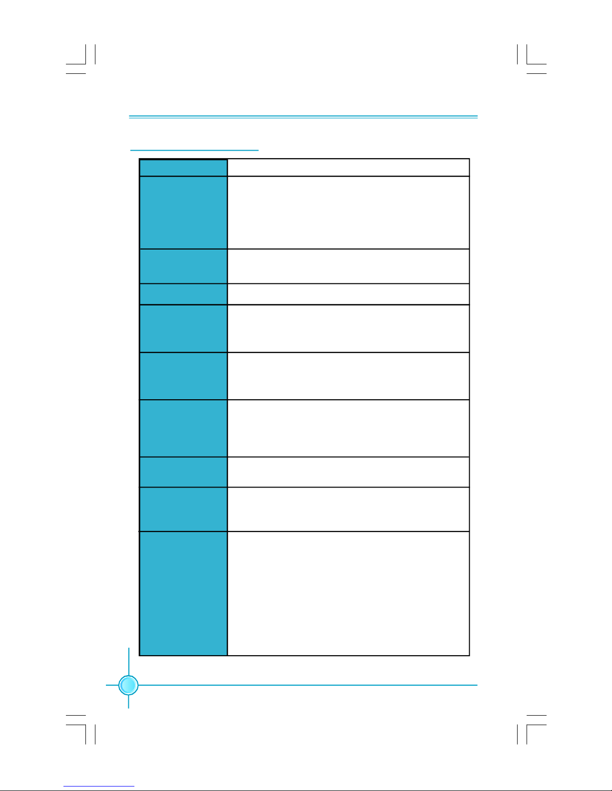
Specifications - - English
Size
CPU
Chipset
Front Side Bus
Memory
·ATX form factor : 305mm x 208mm
· LGA775 socket for Intel
Extreme, CoreTM 2 Duo, Pentium® Dual-Core E2xxx,
Celeron® 4xx, Pentium® 4 Extreme Edition,
Pentium® D, Pentium® 4 processors
· Supports Hyper-Threading Technology
·Northbridge: Intel® P35
·Southbridge: Intel® ICH9
·1333/1066/800 MHz
·2 x 240-pin DIMM slots
·Supports Dual-Channel DDR2 800/667
·Supports up to 4GB
®
Expansion Slots ·2 x PCI Express x16 slots
·1 x PCI Express x1 slot
·3 x PCI slots
Audio
·Realtek 6-channel Audio CODEC / Realtek 8-channel
Audio CODEC
·Supports S/PDIF output, Jack-Sensing function,Intel
High Definition Audio
CoreTM 2 Quad, CoreTM 2
®
LAN
Storage
Rear Panel I/O
2
·Realtek 10/100Mb/s LAN Controller / Realtek Gigabit
LAN Controller
· 4 x SATA 300MB/s devices
· 2 x Ultra DMA 133/100/66 devices
· 1 x eSATA 300MB/s device
·1 x PS/2 Mouse Port
·1 x PS/2 Keyboard Port
·1 x Serial Port(COM1)
·1 x Parallel Port
·1 x Coaxial S/PDIF Output Port
·1 x eSATA Port
·4 x USB 2.0 Ports
·1 x RJ45 LAN Port
·6/8-channel Audio Ports
(continued on the next page)
Page 9

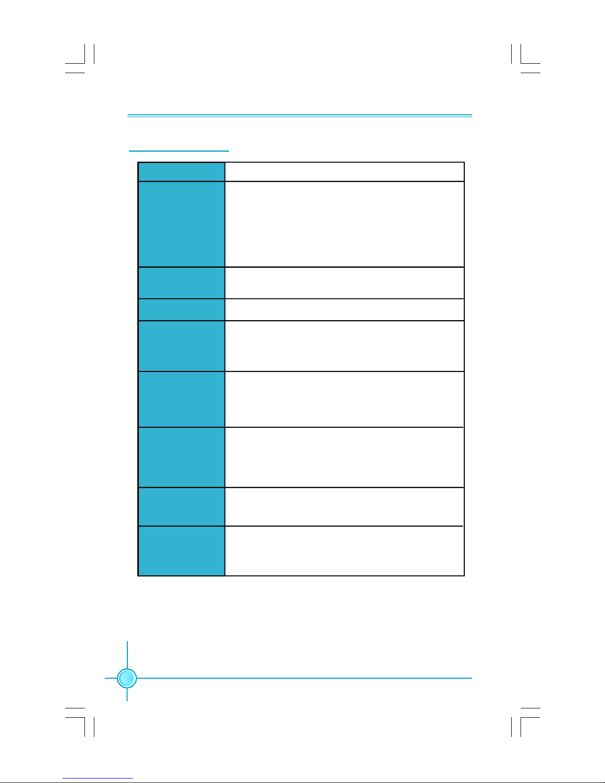
Chapter 1 Main Features
Internal I/O
Connectors
Support CD
·4 x USB 2.0 headers(supports 8 USB 2.0 ports)
·4 x SATA connectors
·1 x Floppy connector
·1 x IDE connector
·1 x Chassis intruder header(INTR) (optional)
·1 x CD_IN header
·1 x Speaker header (optional)
·1 x COM2 header (optional)
·1 x Front Audio connector
·1 x 24-pin ATX Power Connector
·1 x 8-pin ATX_12V Power Connector
·1 x IrDA header (optional)
·1 x CPU Fan connector
·1 x System Fan connector
·2 x Other Fan connectors
·Front panel connector
· Driver
· Utility
·Specifications are subject to change without notice
3
Page 10
第一章
主要性能
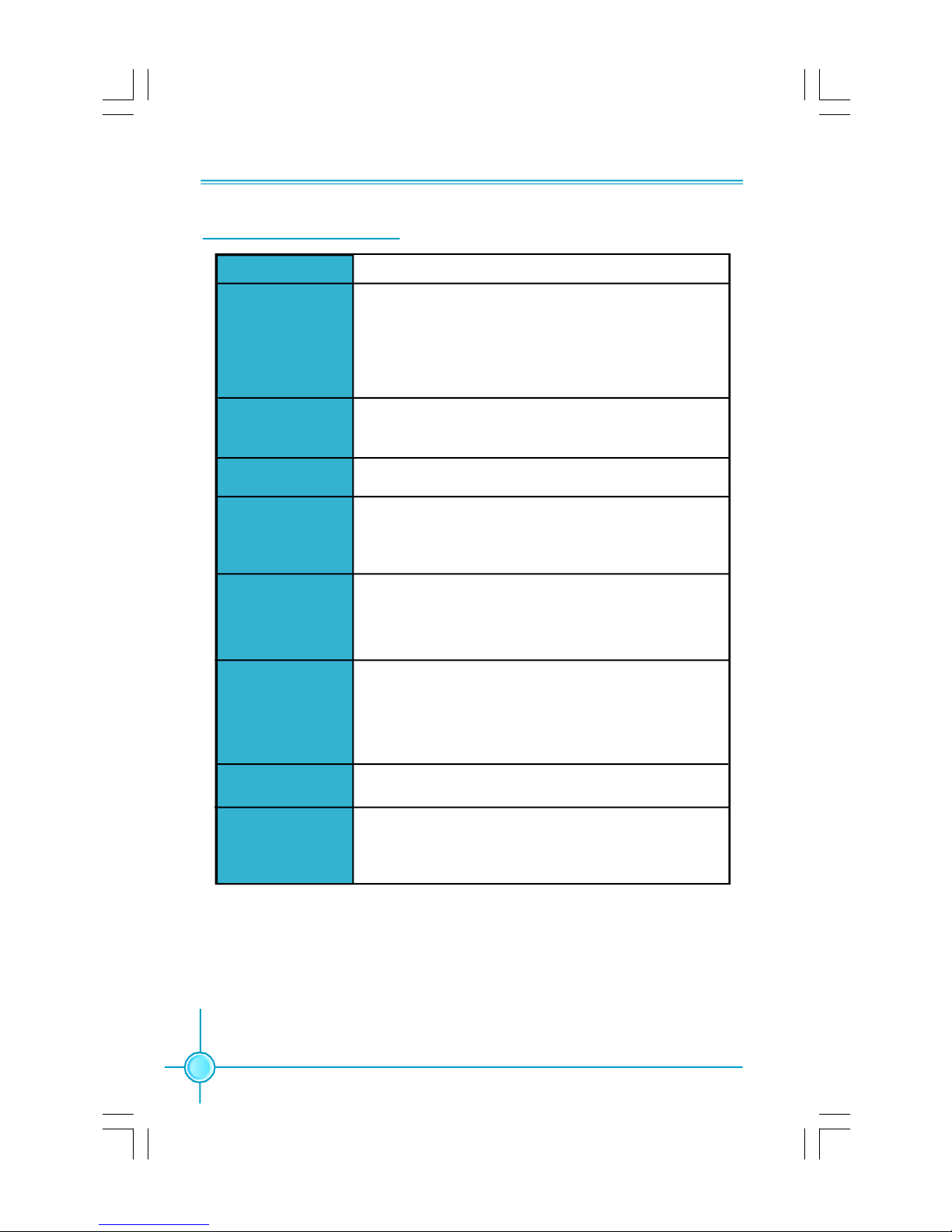
产品规格- -简体中文
尺寸
中央处理器
芯片组
系统总线
内存
扩展槽
音频
· ATX 结构: 305mm x 208mm
· 支持采用 LGA775 封装的 Intel® CoreTM 2 Quad,
CoreTM 2 Extreme,CoreTM 2 Duo,Pentium® Dual-Core
E2xxx, Celeron® 4xx, Pentium® 4 Extreme
Edition,Pentium® D,Pentium® 4 处理器
· 支持 Hyper-Threading 技术
·北桥:Intel® P35
·南桥:Intel® ICH9
·1333/1066/800 MHz
·2 个 240针脚内存插槽
· 支持双通道 DDR2 800/667
· 内存总容量最大可达 4GB
·2 个 PCI Express x16 插槽
·1 个 PCI Express x1 插槽
·3 个 PCI 插槽
·Realtek 6 声道音频编解码器/ Realtek 8 声道音频
编解码器
·支持 S/PDIF 输出,Jack-Sensing 功能, Intel
High Definition Audio
®
LAN
存储
4
·Realtek 10/100 Mb/s LAN Controller/ Realtek
Gigabit LAN Controller
·4 个 SATA 300MB/s 设备
·2 个 Ultra DMA 133/100/66 设备
·1 个 eSATA 300MB/s 设备
(下页继续)
Page 11

第一章
主要性能
后面板I/O
内置连接器
·1 个 PS/2 鼠标接口
·1 个 PS/2 键盘接口
·1 个 串行接口(COM1)
·1 个 并行接口
·1 个 同轴 S/PDIF 数码音频输出接口
·1 个 eSATA 接口
·4 个 USB 2.0 接口
·1 个 RJ45 网络接口
·6/8声道音频接口
·4 个 USB 2.0 接头(提供 8 USB 2.0 接口)
·4 个 SATA 接头
·1 个 软驱接口
·1 个 IDE 接口
·1 个 机箱开启侦测接头(选配)
·1 个 CD_IN 接头
·1 个 Speaker 接头(选配)
·1 个 COM2 接头(选配)
·1 个 前置音频接头
·1 个 24 针ATX 电源接口
·1 个 8 针 ATX_12V 电源接口
·1 个 红外线通讯接头(选配)
·1 个 CPU 风扇接头
·1 个 系统风扇接头
·2 个 其它风扇接头(FAN1,FAN2)
·前端面板接头
实用程序光盘
·规格若有任何更改,恕不另行通知
·驱动程序
·应用程序
5
Page 12

Kapitel 1 Hauptmerkmale
Technische Daten--Deutsch
Größe
CPU
Chipsatz
Front Side Bus
Speicher
Erweiterungs
steckplätze
Audio
·ATX-Formfaktor: 305 mm x 208 mm
· LGA775-Sockel für Intel®_ CoreTM 2 Quad-, CoreTM 2
Extreme-, CoreTM 2 Duo-, Pentium®_Dual-Core E2xxx-,
Celeron®_4xx-, Pentium®_4 Extreme Edition-, Pentium®_D-,
Pentium®_4-Prozessoren
· Unterstützt Hyper-Threading-Technologie
·Northbridge: Intel P35
·Southbridge: ICH9
·1333/1066/800 MHz
·2 x 240-polige DIMM-Steckplätze
· Unterstützt Dual-Channel DDR2 800/667
·Unterstützt bis 4 GB
·2 x PCI Express x16-Steckplätze
·1 x PCI Express x1-Steckplatz
·3 x PCI-Steckplätze
·Realtek 6-Kanal-Audio CODEC / Realtek 8-Kanal-Audio
CODEC
·Unterstützt S/PDIF-Ausgang, Anschlusserkennung, Intel®
High Definition Audio
LAN
Speichergeräte
6
·Realtek 10/100 Mb/s LAN / Realtek Gigabit LAN
· 4 x SATA-Geräte, 300 MB/s
· 2 Ultra DMA 133/100/66-Geräte
· 1 x eSATA 300MB/s Gerät
(Fortsetzung auf der nächsten Seite)
Page 13

Kapitel 1 Hauptmerkmale
I/O-Anschlüsse an
der Rückseite
Interne I/OAnschlüsse
·1 x PS/2-Mausanschluss
·1 x PS/2-Tastaturanschluss
·1 x Seriellanschluss(COM1)
·1 x Parallelanschluss
·1 x Koaxialer S/PDIF-Ausgang-Port
·1 x eSATA-Port
·4 x USB 2.0-Ports
·1 x RJ45-LAN-Port
·6/8-Kanal-Audio-Ports
·4 x USB 2.0-Anschlussleisten (Unterstützung für 8 USB
2.0-Ports)
·4 x SATA-Anschlüsse
·1 x Diskettenlaufwerkanschluss
·1 x IDE-Anschluss
·1 x Gehäuse-offen-Anschluss (INTR)(optional)
·1 x CD_IN-Anschluss
·1 x Lautsprecher-Anschluss(optional)
·1 x COM2-Anschluss(optional)
·1 x Front-Audio-Anschluss
·1 x ATX Power, 24-polig-Anschluss
·1 x ATX_12V Power, 8-polig-Anschluss
·1 x IrDA-Anschluss(optional)
·1 x CPU-Lüfter-Anschluss
·1 x Systemlüfter-Anschluss
·2 x Anderer Lüfter-Anschlüsse
·Frontbedienfeld-Anschluss
Support-CD
·Angaben können sich ohne Vorankündigung ändern.
· Treibe
· Dienstprogramme
7
Page 14
Capítulo 1 Principales funciones
Características- - Español
Tamaño
CPU
Conjunto de chips
Bus frontal
Memoria
Ranuras
de expansión
Audio
·ATX factor de forma: 305mm x 208mm
· Conector LGA775 para procesadores Intel ® CoreTM 2
Quad, CoreTM 2 Extreme, CoreTM 2 Duo, Pentium® Dual Core E2xxx, Celeron® 4xx, Pentium® 4 Extreme Edition,
Pentium® 4, Pentium® D
· Compatible con Hyper-Threading
·Northbridge: Intel P35
·Southbridge: ICH9
·1333/1066/800 MHz
·2 x ranuras DIMM de 240-pin
·Compatible DDR 2 de doble canal 800/667
·Compatible con hasta 4GB
·2 x ranuras PCI Express x16
·1 x ranura PCI Express x1
·3 x ranuras PCI
·Realtek 6 canales Audio CODEC / Realtek 8canales Audio
CODEC
·Compatible salida S/PDIF, sensible a conexión, sonido
Intel® de Alta Definición
LAN
Almacenamiento
8
·Realtek 10/100 Mb/s LAN / Realtek Gigabit LAN
· 4 x dispositivos SATA 300MB/s
· 2 x dispositivos Ultra DMA 133/100/66
· 1 x dispositivo eSATA 300MB/s
(continúa en la página siguiente)
Page 15

Capítulo 1 Principales funciones
Panel de E/S
trasero
Conectores
internos de E/S
·1 x Puerto de ratón PS/2
·1 x Puerto de teclado PS/2
·1 x Puerto Serie(COM1)
·1 x Puerto Paralelo
·1 x Puerto de salida coaxial S/PDIF
·1 x Puerto de eSATA
·4 x Puertos USB 2.0
·1 x Puerto LAN RJ45
·Puertos 6/8 canales Audio
·4 x Cabeceras USB 2.0 (admite 8 puertos USB 2.0)
·4 x Conectores SATA
·1 x Conector de disco flexible
·1 x Conector de IDE
·1 x Cabecera de intrusos en bastidor (INTR)(opcional)
·1 x Cabecera de CD_IN
·1 x Cabecera de altavoz(opcional)
·1 x Conector de COM2 (opcional)
·1 x Conector de Audio frontal
·1 x Conector de 24-pin ATX Power
·1 x Conector de 8-pin ATX_12V Power
·1 x Cabecera de IrDA(opcional)
·1 x Conector de Ventilador de CPU
·1 x Conector de Ventilador Sistema
·2 x Conector de Otro ventilador
·Conector de panel frontal
CD de soporte
·Controlador
·Utilidades
·Las características se encuentran sujetas a cambios sin aviso previo.
9
Page 16

Capítulo 1 Principais características
Especificações- -Portugués
Tamanho
CPU
Chipset
FSB (Front Side
Bus)
Memória
Ranhuras de
expansão
Áudio
·Factor de forma ATX de 305 x 208 mm
· Socket LGA775 para processadores Intel ® _CoreTM 2
Quad, CoreTM 2 Duo, CoreTM 2 Extreme, Pentium®_Dual Core E2xxx, Celeron®_4xx, Pentium®_4 Extreme Edition,
Pentium®_D, Pentium®_4
· Suporta a tecnologia Hyper-Threading
·Northbridge: Intel P35
·Southbridge: ICH9
·1333/1066/800 MHz
·2 ranhuras DIMM de 240 pinos
·Suporta módulos de memória DDR2 800/667 de canal duplo
·Suporta até 4 GB
·2 ranhuras PCI Express x16
·1 ranhura PCI Express x1
·3 ranhuras PCI
·Realtek 6 canais, codec de áudio / Realtek com 8 canais,
codec de áudio
·Suporta saída S/PDIF, função Jack-Sensing, áudio de alta
definição da Intel®
LAN
Armazenamento
10
·Realtek 10/100 Mb/s LAN / Realtek Gigabit LAN
· 4 dispositivos SATA de 300 MB/s
· 2 dispositivos Ultra DMA 133/100/66
· 1 dispositivo eSATA 300MB/s
(continua na página seguinte)
Page 17

Capítulo 1 Principais características
Entrada/Saída
pelo painel
traseiro
Conectores
internos de
entrada/saída
·1 x Porta para rato PS/2
·1 x Porta para Teclado PS/2
·1 x Porta série (COM1)
·1 x Porta paralela
·1 x Porta saída S/PDIF coaxial
·1 x Porta eSATA
·4 x Portas USB 2.0
·1 x Porta LAN RJ45
·Portas 6/8 canais, áudio
·4 x Conectores USB 2.0 (para 8 portas USB 2.0)
·4 x Conectores SATA
·1 x Conector da unidade de disquetes
·1 x Conector IDE
·1 x Conector para detecção de intrusão no chassis(INTR)
(opcional)
·1 x Conector CD_IN
·1 x Conector de altifalante (opcional)
·1 x Conector da COM2 (opcional)
·1 x Conector Áudio frontal
·1 x Conector de alimentação ATX de 24 pinos
·1 x Conector de alimentação ATX de 8 pinos e de 12 V
·1 x Conector IrDA (opcional)
·1 x Conector da ventoinha da CPU
·1 x Conector ventoinha do sistema
·2 x Conectores Outra ventoinha
·Conector de painel frontal
CD de suporte
·As especificações estão sujeitas a alteração sem aviso prévio.
·Controlador
·Utilitários
11
Page 18

Capitolo 1 Caratteristiche principali
Specifiche- -Italiano
Dimensioni
CPU
Chipset
FSB (Front Side
Bus)
Memoria
Alloggi
d’espansione
Audio
·Formato ATX: 305 mm x 208 mm
· Socket LGA775 per processori Intel® CoreTM 2 Quad,
CoreTM 2 Extreme, CoreTM 2 Duo, Pentium® Dual-Core
E2xxx, Celeron® 4xx, Pentium® 4 Extreme Edition,
Pentium® D, Pentium® 4
· Supporto tecnologia Hyper-Threading
·Northbridge: Intel P35
·Southbridge: ICH9
· 1333/1066/800 MHz
·2 alloggi DIMM 240 pin
·Supporto DDR2 800/667 Dual-Channel
·Supporto fino a 4GB
·2 Alloggi PCI Express x16
·1 Alloggio PCI Express x1
·3 Alloggi PCI
·Realtek 6-canali audio CODEC / Realtek 8-canali audio
CODEC
·Supporto output S/PDIF, funzione di rilevamento
connettori, Intel® High Definition Audio
LAN
Archivio
12
·Realtek 10/100 Mb/s LAN / Realtek Gigabit LAN
·4 dispositivi SATA 300MB/s
·2 dispositivi Ultra DMA 133/100/66
·1 dispositivo eSATA 300MB/s
(segue alla pagina successiva)
Page 19

Capitolo 1 Caratteristiche principali
Pannello
posteriore I/O
Connettori I/O
interni
·1 x Porta mouse PS/2
·1 x Porta tastiera PS/2
·1 x Porta Seriale (COM1)
·1 x Porta Parallela
·1 x Porta output coassiale S/PDIF
·1 x Porta eSATA
·4 x Porta USB 2.0
·1 x Porta LAN RJ45
·Porta 6/8-canali audio
·4 x Collettori USB 2.0 (supportano 8 porte USB 2.0)
·4 x Connettori SATA
·1 x Connettore Floppy
·1 x Connettore IDE
·1 x Collettore intrusione telaio (INTR)(optional)
·1 x Collettore CD_IN
·1 x Collettore altoparlante(optional)
·1 x Collettore COM2 (optional)
·1 x Connettore Audio frontale
·1 x Connettore potenza ATX 24 pin
·1 x Connettore potenza ATX_12V 8 pin
·1 x Connettore IrDA(optional)
·1 x Connettore ventolina CPU
·1 x Connettore ventolina di sistema
·2 x Connettori altra ventolina
·Connettore pannello frontale
CD di supporto
·Driver
·Utilità
·Le specifiche tecniche sono soggette a cambiamenti senza preavviso.
13
Page 20

Глава 1 Основные характеристики
Технические характеристики- -Русский
Размер
Процессор
Набор микросхем
Частота
системной шины
Память
Слоты
расширения
Звук
·Форм-фактор ATX размером 305 х 208 мм
· Гнездо LGA775 для процессоров Intel®_ CoreTM 2
Quad, CoreTM 2 Extreme, CoreTM 2 Duo, Pentium®_Dual-
Core E2xxx, Celeron®_4xx, Pentium®_4 Extreme Edition,
Pentium®_D, Pentium®_4
· Поддержка технологии Hyper-Threading
·Северный мост: Intel P35
·Южный мост: ICH9
·1333, 1066, 800 МГц
·2 240-контактных гнезда DIMM
·Поддержка Двухканальная память DDR2 800, 667
·Поддержка до 4 Гб
·2 слота PCI Express x16
·1 слот PCI Express x1
·3 слота PCI
·Realtek 6 каналов, звуковой КОДЕК / Realtek 8 каналов,
звуковой КОДЕК
·Поддержка Выход S/PDIF, функция определения
разъема, поддержка технологии Intel® High Definition
Audio
ЛВС
Устройство
хранения
14
·Realtek ЛВС10/100 Мбит/с / Realtek Gigabit ЛВС
·4 устройства с интерфейсом SATA и скоростью
передачи данных 300 Мб/с
·2 устройства с интерфейсом Ultra DMA 133/100/66
·1 устройствo eSATA 300 Мб/с
(продолжение на следующей странице)
Page 21

Глава 1 Основные характеристики
Входы и
выходы на
задней панели
Встроенные
входы и
выходы
·1 Порт мыши PS/2
·1 Порт Клавиатура PS/2
·1 Последовательный порт (COM1)
·1 Параллельный порт
·1 Порт коансианьный выходы S/PDIF
·1 Порт eSATA Port
·4 Порты USB 2.0
·1 Разъем ЛВС RJ45
·Порты 6, 8 каналов, звуковой
·4 Разъемы USB 2.0 (поддержка 8 портов USB 2.0)
·4 Разъемы SATA
·1 Разъем дисковода гибких дисков
·1 Разъем IDE
·1 Разъем датчика открывания корпуса (INTR)
(дополнительный)
·1 Разъем CD_IN
·1 Разъем Динамик (дополнительный)
·1 Разъем COM2 (дополнительный)
·1 Передний звуковой разъем
·1 Разъем 24-контактный ATX
·1 Разъем 8-контактый ATX_12V
·1 ИК-порт (дополнительный)
·1 Разъем Вентилятор процессора
·1 Разъем системный вентилятор
·2 Разъемы другой вентилятор
·Передняя панель разъем
Поддержка
компакт-дисков
·Технические характеристики могут изменяться без уведомления.
·Драйвер
·Служебная программа
15
Page 22

لﺼﻔﻟﺍ1 ﺔﻴﺴﻴﺌﺭﻟﺍ ﺹﺌﺎﺼﺨﻟﺍ
ﺔﻴﺯﻜﺭﻤﻟﺍ ﺔﺠﻟﺎﻌﻤﻟﺍ ﺓﺩﺤﻭ
ﺕﺎﻔﺼﺍﻭﻤﻟﺍ - -ﻲﺒﺭﻌﻟﺍﺓ
Ÿ ﻉﻭﻨ ﻥﻤ ﺔﻴﻭﺎﺤ ATX ﺱﺎﻘﻤ 305ﻡﻤ × 208ﻡﻤ
Ÿ ﺱﺒﻘﻤLGA775 ﺕﺎﺠﻟﺎﻌﻤﻟ Intel®_ CoreTM 2 QuadﻭCoreTM 2 Duoﻭ
Celeron®_4xx ﻭ Pentium®_Dual-Core E2xxxﻭ CoreTM 2 Extreme
Pentium®_4ﻭ Pentium®_Dﻭ Pentium®_4 Extreme Edition.
Ÿ ) ﻕﺌﺎﻔﻟﺍ ﻁﺒﺭﻟﺍ ﺔﻴﻨﻘﺘ ﻡﻋﺩHyper-Threading(
Ÿ ) ﻲﻟﺎﻤﺸﻟﺍ ﺭﺴﺠﻟﺍNorthbridge:( Intel P35
Ÿ ) ﻲﺒﻭﻨﺠﻟﺍ ﺭﺴﺠﻟﺍSouthbridge:( ICH9
ﻲﻤﺎﻤﻷﺍ ﺏﻨﺎﺠﻟﺍ لﻗﺎﻨ
Ÿ 800/1066/1333ﺯﺘﺭﻫ ﺎﺠﻴﻤ
ﻡﺠﺤﻟﺍ
ﻕﺌﺎﻗﺭﻟﺍ
Ÿ ﺩﺩﻋ2 ﺕﺎﺤﺘﻓDIMM × 240 ﺎﺴﻭﺒﺩ
Ÿ ﺓﺎﻨﻘﻟﺍ ﻲﺌﺎﻨﺜ ﻡﻴﻤﺼﺘﻟﺍ ﻡﻋﺩDual-Channel DDR2 800/667
Ÿ ﻰﻟﺇ لﺼﻴ ﻡﻋﺩ4ﺕﻴﺎﺒ ﺎﺠﻴﺠ
Ÿ ﺩﺩﻋ2 ﺢﺘﻓﺓ PCI Express x16
Ÿ ﺩﺩﻋ1 ﺔﺤﺘﻓPCI Express x1
Ÿ ﺩﺩﻋ3ﺕﺎﺤﺘﻓ PCI
Ÿ ﺔﻴﻨﻘﺘﺒ ﺕﺍﻭﻨﻗ ﺕﺴﺒ ﻲﺘﻭﺼ ﺯﻴﻤﺭﺘ / Realtek ﺯﻴﻤﺭﺘ ﻲﺘﻭﺼ ﻥﺎﻤﺜﺒ ﺕﺍﻭﻨﻗ ﺔﻴﻨﻘﺘﺒ Realtek
Ÿ ﺝﺭﺨ ﻡﻋﺩS/PDIFﺔﻴﻨﻘﺘ ،ﺱﺒﻘﻤﻟﺍ ﺭﺎﻌﺸﺘﺴﺍ ﺔﻔﻴﻅﻭ ،Intel® High Definition Audio
ﺔﻴﻠﺤﻤﻟﺍ لﺎﺼﺘﻻﺍ ﺔﻜﺒﺸ
Ÿ Realtek Gigabit LAN / Realtek 10/100 Mb/s LAN
Ÿ ﺩﺩﻋ2 ﺓﺯﻬﺠﺃUltra DMA 133/ 100/66
Ÿ ﺩﺩﻋ4 ﺓﺯﻬﺠﺃSATA 300MB/s
Ÿ ﺩﺩﻋ1 زﺎﮭﺟ eSATA 300MB/s
Ÿ ﺩﺩﻋ1 ﺱﻭﺎﻤ ﺫﻔﻨﻤ PS/2
Ÿ ﺩﺩﻋ1 ﺢﻴﺘﺎﻔﻤ ﺔﺤﻭﻟ ﺫﻔﻨﻤPS/2
Ÿ ﺩﺩﻋ1 ﻲﻠﺴﻠﺴﺘ ﺫﻔﻨﻤ(COM1)
Ÿ ﺩﺩﻋ1 ﻱﺯﺍﻭﺘﻤ ﺫﻔﻨﻤ
Ÿ ﺩﺩﻋ1 ﺝﺭﺨ ﺫﻔﻨﻤS/PDIFﺭﻭﺤﻤﻟﺍ ﺩﺤﺘﻤ
Ÿ ﺩﺩﻋ1 ﺫﻔﻨﻤeSATA
Ÿ ﺩﺩﻋ4 ﺫﻓﺎﻨﻤUSB 2.0
Ÿ ﺩﺩﻋ1 ﺔﻴﻠﺤﻤ لﺎﺼﺘﺍ ﺔﻜﺒﺸ ﺫﻔﻨﻤRJ45
Ÿ ﺫﻓﺎﻨﻤ/ ﺕﺴﺒ ﻲﺘﻭﺼ ﻥﺎﻤﺜﺒ ﺔﻴﻨﻘﺘﺒ ﺕﺍﻭﻨﻗ
ﺓﺭﻜﺍﺫﻟﺍ
ﺔﻌﺴﻭﺘﻟﺍ ﺕﺎﺤﺘﻓ
ﺕﻭﺼﻟﺍ
ﻥﻴﺯﺨﺘﻟﺍ
ﺫﻓﺎﻨﻤ ﺝﺭﺨﻟﺍ/لﺨﺩﻟﺍ
ﺔﺤﻭﻠﻟ ﺔﻴﻔﻠﺨﻟﺍ
16
ﺔﻴﻟﺎﺘﻟﺍ ﺔﺤﻔﺼﻟﺍ ﻊﺒﺎﺘ
Page 23

/ لﺨﺩﻟﺍ لﻴﺼﻭﺘ ﺫﻓﺎﻨﻤ
Ÿ ﺩﺩﻋ4 ﻑﺍﺭﻁﺃ لﻴﺼﻭﺘ USB 2.0) ﻡﻋﺩﺘ 8 ﺫﻓﺎﻨﻤ USB 2.0(
Ÿ ﺩﺩﻋ4 لﻴﺼﻭﺘ ﺫﻓﺎﻨﻤSATA
Ÿ ﺩﺩﻋ1ﺔﻨﺭﻤﻟﺍ ﺹﺍﺭﻗﻷﺍ ﻙﺭﺤﻤ لﻴﺼﻭﺘ ﺫﻔﻨﻤ
Ÿ ﺩﺩﻋ1 لﻴﺼﻭﺘ ﺫﻔﻨﻤ IDE
Ÿ ﺩﺩﻋ1 لﻴﺼﻭﺘ ﻑﺭﻁ Intruder لﻜﻴﻬﻠﻟ )(INTR)ﻱﺭﺎﻴﺘﺨﺍ(
Ÿ ﺩﺩﻋ1 لﻴﺼﻭﺘ ﻑﺭﻁ CD_IN
Ÿ ﺩﺩﻋ1ﺔﻋﺎﻤﺴﻟﺍ لﻴﺼﻭﺘ ﻑﺭﻁ )ﻱﺭﺎﻴﺘﺨﺍ(
Ÿ ﺩﺩﻋ1 لﻴﺼﻭﺘ ﻑﺭﻁ COM2)ﻱﺭﺎﻴﺘﺨﺍ(
Ÿ ﻲﻤﺎﻤﻷﺍ ﺕﻭﺼﻟﺍ لﺼﻭﻤ
Ÿ ﺩﺩﻋ1 ﺔﻗﺎﻁ لﺼﻭﻤ ATX ﺀ، 24 ﺱﻭﺒﺩ
Ÿ ﺩﺩﻋ1 ﺔﻗﺎﻁ لﺼﻭﻤ ATX_12V ×8 ﺱﻴﺒﺎﺒﺩ
Ÿ ﺩﺩﻋ 1 لﻴﺼﻭﺘ ﻑﺭﻁ IrDA)ﻱﺭﺎﻴﺘﺨﺍ(
Ÿ ﺩﺩﻋ1 ﺔﻴﺯﻜﺭﻤﻟﺍ ﺔﺠﻟﺎﻌﻤﻟﺍ ﺓﺩﺤﻭﻟ ﺔﺤﻭﺭﻤ
Ÿ ﺩﺩﻋ1ﻡﺎﻅﻨﻟﺍ ﺔﺤﻭﺭﻤﻟ لﺼﻭﻤ
Ÿ ﺩﺩﻋ2لﻴﺼﻭﺘ ﺫﻓﺎﻨﻤ ىﺮﺧأ ﺔﺣوﺮﻣ
Ÿ ﺔﻴﻤﺎﻤﻷﺍ ﺔﺤﻭﻠﻟﺍ لﺼﻭﻤ
ﻡﺩﻤﻟﺍ ﺹﺭﻘﻟﺍ ﻡﻋﺩ Ÿ لﻴﻐﺸﺘﻟﺍ ﺞﻤﺎﻨﺭﺒ
Ÿ ﺕﺍﻭﺩﻷﺍ
لﺼﻔﻟﺍ1ﺔﻴﺴﻴﺌﺭﻟﺍ ﺹﺌﺎﺼﺨﻟﺍ
ﺔﻴﻠﺨﺍﺩﻟﺍ
Ÿ .ﻕﺒﺴﻤ ﺭﺎﻁﺨﺇ ﻥﻭﺩﺒ ﺕﺎﻔﺼﺍﻭﻤﻟﺍ ﺭﻴﻐﺘﺘ ﺩﻗ
17
Page 24

Chapter 1 Main Features
Jumpers
This section explains how to setup jumpers. You should read the following
content carefully prior to modifying any jumper settings.
Attention
The jumpers on the motherboard, pin 1 can be identified by the
bold silkscreen next to it. and in this manual, pin 1 is simply labeled as “ 1”.
Clear CMOS Jumper: CLR_CMOS
The CLR_CMOS jumper allows you to clear the data in CMOS. The data
includes system setup information such as system password, data, time,
and system setup parameters. To clear and reset the system parameters to
default setup, please do as follows:
1. Turn off the computer and unplug the power cord
from the power supply.
2. Move the jumper cap from pins 2-3 (default) to pins
1-2. Keep the cap on pins 1-2 for several seconds,
then move the cap back to pins 2-3.
3. Plug the power cord and turn on the computer.
1
Normal
(default)
1
Clear
CLR_ CMOS
18
Page 25

Chapter 2 BIOS Description
Chapter
This chapter introduces how to change system settings
through the BIOS Setup menus. Detailed descriptions of the
BIOS parameters are also provided.
You have to run the Setup Program when the following cases
occur:
1.An error message appears on the screen during the system
2.You want to change the default CMOS settings.
This chapter includes the following information:
2
POST process.
v Enter BIOS Setup
v Main Menu
v Standard BIOS Features
v Fox Central Control Unit
v Boot Configuration Features
v Advanced BIOS Features
v PCI/PNP Resource Management
v Power Management Features
v Hardware Health Configure
v BIOS Security Features
v Load Optimal Defaults
v Load Failsafe Defaults
v Save Changes and Exit
v Discard Changes and Exit
19
Page 26

Chapter 2 BIOS Description
Enter BIOS Setup
The BIOS is the communication bridge between hardware and software,
correctly setting up the BIOS parameters is critical to maintain optimal system
performance. Power on the computer, when the following message briefly
appears at the bottom of the screen during the POST (Power On Self Test),
press <Del> key to enter the BIOS CMOS Setup Utility.
Press TAB to show POST Screen, DEL to enter SETUP.
Note:
We do not suggest that you change the default parameters in the BIOS Setup,
and we shall not be responsible for any damage that result from any changes
that you make.
Main Menu
The main menu displays a list of options that are available. Use the arrow keys
to select among the items, when the correlative information of the the items will
appear at the bottom, and execute the sub-menu by pressing <Enter>.
The items in the main menu are explained as below:
1. Standard BIOS Features
The basic system configuration can be set up through this menu.
2. Fox Central Control Unit
The special features can be set up by this menu.
3. Boot Configuration Features
This menu is used for Boot setting.
4. Advanced BIOS Features
The advanced system features can be set up through this menu.
5. PCI/PNP Resource Management
The system’s PnP/PCI settings and parameters can be modified by this menu.
20
Main Menu
Page 27

Chapter 2 BIOS Description
6. Power Management Features
Through this menu you can set up all the items of Green function features.
7. Hardware Health Configure
This menu will display the current status of your PC.
8. BIOS Security Features
The user password can be set up through this menu.
9. Load Optimal Defaults
You can load the optimal performance settings by this menu, however,the
stable default values may be affected.
10. Load Failsafe Defaults
You can load the Failsafe default BIOS settings through this menu.
11. Save Changes and Exit
Save CMOS value settings to CMOS and exit setup.
12. Discad Changes and Exit
Abandon all CMOS value changes and exit setup.
1.Standard BIOS Features
This sub-menu is used to set up the standard BIOS parameters, such as the
date, time, floppy driver and so on. Select the item by the arrow keys, and then
use the <+> or <-> keys to choose the setting values.
AMIBIOS/Processor/System Memory
These items show the information of the AMIBIOS/system processor and the
system memory detemined by POST of the BIOS.
1.1 System Time/System Date
This item allows you to set up the desired time and date format (usually as
the current time and date) with <hour><minute><second><day><month>
<date><year> format.
Day—weekday from Sun. to Sat.
Standard BIOS Features Menu
21
Page 28

Chapter 2 BIOS Description
Month—month from 1 to 12
Date—date from 1st to 31
st
Year—year, set up by users.
Use <ENTER>,<TAB> or <SHIFT+TAB]>to select a field.Use <+>or <-> to
configure system time and date.
1.2 Floppy A
This option allows you to select the kind of FDD to be installed, including
[none],[360K, 51/4 in], [1.2M, 51/4in], [720K, 31/2 in], [1.44M, 31/2 in] and
[2.88 M, 31/2 in].
2.Fox Central Control Unit
Fox central control Unit Menu
2.1 Smart power LED
Enable this function, the smart LED can show the system status of POST
process.
2.2 Overclock Options
Fox Ratio Select
Use it to enabled or disabled the Fox Ratio selection.
CPU FSB Type
22
Overclock Options Menu
Page 29

Chapter 2 BIOS Description
This item shows the CPU FSB type.
Memory Target Frequency
This item shows the memory target frequency.
CPU FSB Over clock Choice
This item is used to program the CPU FSB.
PCIE Freq Over Clock(MHz)
This item is used to adjust the PCI slot frequency.
CPU Spread Spectrum
This item is used to set the CPU spread spectrum functions.
NOTE: The Spread Spectrum function can influence the EMI degree.
PCIE Spread Spectrum
This item is used to set the PCIE spread spectrum functions.
NOTE: The Spread Spectrum function can influence the EMI degree.
Memory Remap Feature
This item is used to set the memory remap feature.
DRAM Frequency
This item is used to adjust the DRAM frequency.
Configure DRAM Timing by SPD
This item is used to configure DRAM timing by SPD.
Memory Hole
This item is used to set the memory hole.
2.3 Voltage Options
Voltage Options Menu
Current CPU Voltage/Current Memory Voltage/Current GMCH Voltage
These items show the current CPU/Memory/GMCH voltage.
CPU Voltage Margining Step
This item is used to set the CPU voltage margining offset. Every voltage
margining step is 0.0125V.
23
Page 30

Chapter 2 BIOS Description
Memory Voltage Control
This item is used to change the voltage of memory group.
1.28X Memory Voltage Table
This item is used to enable or disable 1.28X for memory voltage.
1.13X Memory Voltage Table
This item is used to enable or disable 1.13X for memory voltage.
NB/PCIE Voltage Control
This item is used to set the NB/PCIE voltage control.
2.4 CPU Configuration
CPU Configuration menu
Manufacturer/Frequency/FSB Speed/Cache L1/Cache L2/Ratio Status/Ratio
Actual Value
These items show the related information of the CPU that used on the motherboard.
Super Clock Free
This item is used for the Super Clock Free technology.
It is available only when the CPU is not the XE CPU and EIST is enabled.
Intel(R) SpeedStep(tm) tech.
This item is used for the Intel speed step technology.
[Maximum]: CPU speed is set to maximum.
[Minimum]: CPU speed is set to minimum.
[Automatic]: CPU speed controlled by operating system.
[Disabled]: default CPU speed.
C1E Support
This item is used to set the C1E support. It should be enabled in order to
enable or disable the ”Enhanced Halt State”.
Hardware Prefetcher
This item is used to enable or disable the hardware prefetcher function.
Adjacent Cache Line prefetch
This item is used to enable or disable the Adjacent Cache Line prefetch function.
24
Page 31

Chapter 2 BIOS Description
Intel(R) Virtualization Tech
This item is used to enable or disable Intel Virtualization Technology.
CPU TM function
This item is used to enable or disable CPU TM function. For the processorits
CPUID belows 0F41h.
Execute-Disable Bit Capabili
This item allows you to enable or disable the Execute Disable Bit feature.
Execute Disable Bit capability is a robust hardware feature, detectable
using the CPUID instruction, which protects against malicious software
executing code on IA-32 systems.
3. Boot Configuration Features
Boot Configuration Features Menu
3.1 Quick Boot
While Enabled, this option allows BIOS to skip certain tests while booting, this
will decrease the time needed to boot the system.
3.2 Quiet Boot
This item is used to enable or disable the quiet boot.
[Disabled]: Displays normal POST messages.
[Enabled]: Displays OEM Logo instead of POST messages.
3.3 AddOn ROM Display Mode
This item is used to set the display mode for option ROM. When “Quiet Boot”
is enabled, this option controls whether output from the option ROM is displayed.
The available setting values are: Force BIOS; Keep Current.
3.4 Interrupt 19 Capture
This item, when enabled, allows option ROMs to trap interrupt 19.
3.5 Wait For ‘F1’ If Error
This item is used to set whether to wait for ‘F1’ key to be pressed if error
occurs. Enabling this option causes the system to pause the POST if it en counters an error, and wait for user to press the ‘F1’ key before resuming.
25
Page 32

Chapter 2 BIOS Description
3.6 Hit ‘DEL’ Message Display
This item is used to set whether to show the information about press <DEL>
to run BIOS setup in POST.
3.7 Boot Device Priority
This option is used to select the priority for devices. After pressing <Enter>,
you can select the devices using the Up/Down arrow keys, and change the
devices priority using <+> or <->; you can exit this menu by pressing <Esc>.
3.8 Hard Disk Drives
This is used to specify the Boot Device priority for available Hard Disk Drives.
3.9 Removable Drives
This option is used to specify the Boot Device priority sequence from available
removable drives.
4.Advanced BIOS Features
Advanced BIOS Features Menu
Use the arrow keys to select the options and press <Enter> to enter it.
4.1 IDE Configuration
This sub-menu is used for the configuration of IDE/SATA devices. You can
press <Enter> to set the available values of items.
NOTE: The Netghost can not be used on SATA 1 and SATA 2 ports.
4.2 SuperIO Configuration
This sub-menu is used for the configuration of I/O devices, such as Floppy,
Serial Port, Parallel Port and so on.
4.3 OnBoardDevice Configuration
This sub-menu is used for the configuration of onboard devices, such as
USB controller, Graphic Adapter, HDA controller, PEG port and so on.
26
Page 33

Chapter 2 BIOS Description
5.PCI/PNP Resource Management
PCI/PNP Resource Management Menu
5.1 IRQ & DMA Settings
Press <Enter> to enter the IRQ and DMA setup. The available setting values:
IRQ 3/4/5/7/9/10/11/14/15, DMA Channel 0/1/3/5/6/7.
5.2 Plug & Play O/S
This item is used to set the plug and play function for your OS.
[No]: Lets the BIOS configure all the devices in the system.
[Yes]: Lets the operating system configure plug and play devices not required
for boot if your system has a plug and play operating system.
5.3 PCI Latency Timer
This item is used to set the PCI latency timer. The value is in units of PCI clock
for PCI device latency timer register.
5.4 Allocate IRQ to PCI VGA
This item is used to set if allocate IRQ to PCI VGA.
[Yes]: Assigns IRQ to PCI VGA card if card requests IRQ.
[No]: Does not assign IRQ to PCI VGA card even if card requests an IRQ.
5.5 Palette Snooping
This item is used to set whether the palette snooping is enabled.
5.6 PCI IDE BusMaster
This item, when enabled, the BIOS can use PCI bus mastering for reading/
writing to IDE drives.
27
Page 34

Chapter 2 BIOS Description
6.Power Management Features
Power Management Features Menu
6.1 Suspend mode
This item can let you select the ACPI state used for system suspend.
6.2 ACPI Version Features
This item can let you select the ACPI version.
6.3 ACPI APIC support
This item is used to set if add the ACPI APIC table pointer to RSDT pointer
list.
6.4 APIC ACPI SCI IRQ
This item is used to enable or disable the APIC ACPI SCI IRQ. Enabling APIC
mode will expand available IRQs resources.
6.5 USB Device Wakeup From S3/S4
This item allows you to enable or disable the USB device wakeup from S3/S4.
6.6 Restore on AC Power Loss
This item is used to set which state the PC will take with when it resumes after
an AC power loss.
6.7 High performance Event Timer
This item is used to enable or disable the High Performance Event Timer(HPET).
6.8 Enable KB MS wake from S5
This item is used to enable or disable keyboard and mouse
wake_up function from S5.
6.9 Resume On Ring / PME# / RTC Alarm
This item allows you to enable or disable Ring /PME# / RTC alarm event to
generate a wake event.
28
Page 35

Chapter 2 BIOS Description
7.Hardware Health Configure
Hardware Health Configure Menu
7.1 Fan 1 Mode Setting
This item is used to set the fan 1 configuration mode.
7.2 Temperature 1 Limit of Hig/Sec/Thi/Low
These items are used to set the fan temperature limit.
7.3 Fan 1 Highest/Second/Third/Fourth/Lowest Setting
These items are used to set the fan speed.
CPU Temperature /System Temperature/CPU Fan Speed/System Fan
Speed/Vcore/1.8V SUS/1.2V CORE/+5V/+12V/+3.3V/VCC/VSB/VBAT
These items display the current CPU/chipset/system temperature,fan
speed and voltages that are automatically detected by the system.
8.BIOS Security Features
BIOS Security Features Menu
8.1 Change Supervisor Password
This item is used to install or change supervisor password.
8.2 BIOS Write Protect
This item is used to enable or disabled the BIOS write protect function.
29
Page 36

Chapter 2 BIOS Description
8.3 Chassis Intrusion
This item allows you to enable or disable intrusion detection function.
9.Load Optimal Defaults
This menu can let you load the optimized defaults set by BIOS, which have set
the optimized performance parameters of system to improve the performances
of system components.You can select <Y> or <N> and then press <Enter> to
load or not load the optimized defaults.
10.Load Failsafe Defaults
This menu allows you to load defaults set by BIOS ,which have set the basic
functions of system in order to ensure the stability of system.You can select <Y>
or <N> and then press <Enter> to load or not load defaults.
11.Save Changes and Exit
When you select this option and press <Enter>, the following message will
appear in the center of the screen:
SAVE to CMOS and EXIT (Y/N)?Y
Press <Y> to save your changes in CMOS and exit the program; press <N> or
<ESC> to return to the main menu.
12.Discard Changes and Exit
If you select this option and press <Enter>, the following message will appear
in the center of the screen:
Quit Without Saving (Y/N)?Y
Press <Y> to exit CMOS without saving your modifications; press <N> or
<ESC> to return to the main menu.
30
Page 37

Chapter 4 Driver CD Introduction
Chapter
This chapter will introduce how to use bundled software.
This chapter provides the following information:
3
3
v FOX ONE
v FOX LiveUpdate
v FOX LOGO
v FOX DMI
31
Page 38

Chapter 3 Directions for Bundled Software
FOX ONE
FOX ONE is a powerful utility for easily modifying system settings. It also allows
users to monitor various temperature values, voltage values, frequency and fan
speed at any time.
With FOX ONE, you can modify system performance settings such as bus speed,
CPU voltage, fan speed, and other system performance options that are supported
by the BIOS and you also can monitor hardware temperature, voltage, frequency
and fan speed.
Supported Operating Systems:
-Windows 2000 -Windows XP (32-bit and 64-bit)
-Windows 2003 (32-bit and 64-bit) -Windows Vista (32-bit and 64-bit)
Using FOX ONE:
1. Main Page
Show CPU Information
Use the toolbar to navigate to
other pages
Alert Lamp
Switch Button
Skin Button
Exit
Minimum
Configuration
Homepage
Alert Lamp
When the system is in healthy status, the alert lamp color is green. And if the system
is in abnormal status,the alert lamp color will turn red.
Switch Button
Click this button, it will simplify the interface to HW monitor information bar as the
below figure shows. The bar could help you to monitor if your system is in the
healthy status at any time.
32
Monitor Frequency/Voltage/Fan speed/Temperature value
Page 39

Chapter 3 Directions for Bundled Software
Click here to return to
previous status
Skin Button
Click this button, you will see the additive figures such as “crystal”and “rock”.Please
select your favorite skin.
Exit
Click this button to exit the program.
Minimum
Click this button to minimize the window.
Configuration
This function is used to configurate the parameters for the program. It deter-
mines which items will be shown in simple mode.Besides,it also provides F.I.S
calibration function which will re-calibrate the CPU’s loading. F.I.S calibration
function is optional.
Homepage
Click this button to visit FOXCONN motherboard website.
2. CPU Page - CPU Control
This page is used to select and run the CPU frequency to determine the current
performance level of the system. You can adjust manually or select “Auto
Overclock”. Otherwise, it also provides FOX Intelligent Stepping,But this function
is optional.
Go to CPU page
Reset the
changes
Select the different
benchmarks
Close this page
Auto
Overclocking
Ajust by manual
Apply the
changes
33
Page 40

Chapter 3 Directions for Bundled Software
3. Freq. Page - Frequency Control
In this page ,you can set memory and PCI Express frequency manually.
Go to Freq. page
Close this page
Select the option
you want to set
Adjust manually
Reset the changes
Apply the changes
4. Limit Setting - Adjust page
This page includes five different sections. “CPU Temp.” and “Sys Temp.” will help
you to set high limit temperature. “CPU Fan”, “Sys. Fan” and“FAN1 fan” are used
to set low limit rpm. And all of them have alert function.
Go to Limit Setting page
Set high limit by dragging the lever
Show current CPU temperature value
Enable alert function
when the CPU
temperature is higher
than high limit value
Show current high
limit value of CPU
temperature
5. Voltage Page - Voltage Control
This page allows you to set CPU , memory and North Bridge voltage manually.
34
Page 41

Chapter 3 Directions for Bundled Software
Go to Voltage page
Select the option
you want to set
Adjust manually
Reset the changes
Apply the changes
6. Fan Page - Fan Control
This page allows you to enable Smart Fan function and set fan speed manually.
Go to Fan page
Enable or disable
smart fan function
Set fan speed by
dragging the lever
Apply the changesReset the changes
FOX LiveUpdate
FOX LiveUpdate is a useful utility to backup and update the system BIOS online
or locally.Drivers and utilities are aslo can be updated online.
Supported Operating Systems:
-Windows 2000 -Windows XP (32-bit and 64-bit)
-Windows 2003 (32-bit and 64-bit) -Windows Vista (32-bit and 64-bit)
35
Page 42

Chapter 3 Directions for Bundled Software
Using FOX LiveUpdate:
1. Local Update
“BIOS Info” tells you the system BIOS information; “Backup BIOS” could
backup your system BIOS ,please click this button ,then key in a BIOS name
and save it ; “Update BIOS” helps to update your system BIOS from local BIOS
files ,please follow the wizard to finish the operation.
Exit
Link to website
Minimum
Toolbar
Show current
BIOS information
2. Online Update
This area lets you update your system BIOS,Drivers,Utilities and all of them from
Internet. Click “start”, it will search the new BIOS ,Drivers and Utilities from Internet.
Then follow the wizard to finish the update operation.
Current
Click here
information
Search new BIOS,
Drivers and
Utilities from Internet
3. Configure
“Option” provides auto search options and version filter. After setting the auto search
options, the utility will work in the background and the related information will show in
a pop balloon notification;
36
Page 43

Chapter 3 Directions for Bundled Software
click the “System” button,you can set the backup BIOS location and change different
skin of the utility;“Advance”helps you to flash BIOS,Boot Block and clear CMOS ,we
recommend that you keep the default setting
unchanged to avoid damagement.
Set auto
search options
Click here
Apply the
changes
4. About & Help
This page shows some information about FOX LiveUpdate.
Click here
FOX LOGO
Select search
which kind of
versions
Reset to default
value
Show information
about FOX
LiveUpdate
FOX LOGO is a simple and useful utility to backup, change and delete the boot
Logo. The boot Logo is the image that appears on screen during the Power-On
Self-Tests (POST).
Supported Operating Systems:
-Windows 2000 -Windows XP (32-bit and 64-bit)
-Windows 2003 (32-bit and 64-bit) -Windows Vista (32-bit and 64-bit)
Using FOX LOGO:
37
Page 44

Chapter 3 Directions for Bundled Software
Main Page
Main screen
Backup
Change
Delete
Exit
Minimize
Website
About
Warning:
When you change Logo or delete current Logo, the system will flash BIOS
file automatically.During this time , please DO NOT shut down the application
and the system ,or the motherboard will be damaged seriously.
FOX DMI
FOX DMI is a full DMI information viewer,and it supports three kinds of DMI Data
format :Report , Data Fields and memory Dump.
Supported Operating Systems:
-Windows 2000 -Windows XP (32-bit and 64-bit)
-Windows 2003 (32-bit and 64-bit) -Windows Vista (32-bit and 64-bit)
Using FOX DMI:
Please operate this utility as the comments shows .
Click here to select
the type you want
to view.
38
Click here to select
the DMI Data format
you need
 Loading...