


8288 451 100
Owner’s Manual
Digital Multitracker
INPUT MON OUT PHONES
1/9/A |
2/10/B |
3/11/C |
4/12/D |
5/13/E |
6/14/F |
|
7/15/G |
|
|
|
8/16/H |
L |
R |
|
|
|
|
|
|
|
BAL |
UNBAL |
INSERT |
BAL |
|
UNBAL |
INSERT |
|
|
|
|
|
|
TRIM |
|
|
|
|
MON OUT |
PHONES |
|
|||
LINE |
MIC LINE MIC LINE MIC |
LINE MIC |
LINE MIC |
LINE MIC |
LINE MIC |
LINE |
MIC |
0 10 |
0 |
10 |
DIGITAL |
|||
MULTITRACKER |
||||||||||||||
PEAK |
PEAK |
PEAK |
PEAK |
PEAK |
PEAK |
PEAK |
PEAK |
|
|
|
||||
|
|
|
|
|||||||||||
1/9/A |
2/10/B |
3/11/C |
4/12/D |
5/13/E |
6/14/F |
7/15/G |
8/16/H |
|
|
|
|
|
|
|
|
|
|
|
||
CH STATUS |
ORANGE |
INPUT |
RED |
REC |
GREEN |
PLAY |
OFF |
MUTE |
|
|
|
|
|
|
|
|
|
|
|
|
|
|
|
CH STATUS/CH SEL |
|
|
|
|
|
SCENE |
|
|
|
|
|
|
|
|
|||
|
|
|
|
|
|
|
|
|
|
RECALL |
STORE |
|
|
|
|
|
|
|
|
|
|
|
|
|
|
|
|
|
|
|
|
|
|
OPTICAL |
|
|
|
|
|
|
|
|
|
|
|
|
|
|
|
|
|
DIRECT RCL |
MAP |
|
|
|
|
|
|
|
|
|
|
|
|
|
|
|
|
|
|
|
|
CLEAR |
|
|
|
|
|
|
|
|
|
|
|
|
|
|
|
|
|
|
|
|
EFF EDIT |
|
|
|
|
|
|
|
|
|
|
|
|
|
|
|
|
|
|
|
EFF1 |
EFF2 |
|
|
|
|
|
|
|
|
|
+6 |
+6 |
+6 |
+6 |
|
+6 |
+6 |
|
+6 |
+6 |
|
|
|
ACCESS |
|
|
|
|
|
|
|
|
|
|
|
|
|
|
|
|
|
|
|
|
||||||||
|
|
|
|
|
|
|
|
|
|
MUTE |
MUTE |
|
|
|
|
|
|
|
|
|
|
|
|
|
|
|
|
|
|
|
|
CH PARAM EDIT |
PHANTOM |
|
|
|
|
|
|
|
|
0 |
0 |
0 |
0 |
|
0 |
0 |
|
0 |
0 |
|
|
EQ/COMP |
|
|
|
|
|
|
|
|
|
|
EFF1/EFF2 |
HI-G/F/Q |
|
|
|
|
|
|
|
|
|||||||||
|
|
|
|
|
|
|
|
|
|
PRE/POST |
COMP |
|
REC ASSIGN |
|
|
|
|
|
||
|
|
|
|
|
|
|
|
|
|
|
|
|
BUSS |
DIRECT |
|
|
|
|
|
|
-10 |
-10 |
-10 |
-10 |
|
-10 |
-10 |
|
-10 |
-10 |
|
|
INPUT SEL |
SOURCE |
REC TRK |
REC TRK |
|
DISP SEL PGM SEL |
SETUP |
||
|
|
|
|
|
|
|
|
|
|
AUX1/AUX2 |
MID-G/F/Q |
|
|
|
|
|
|
|
|
|
-20 |
-20 |
-20 |
-20 |
|
-20 |
-20 |
|
-20 |
-20 |
|
|
|
|
|
|
|
|
|
|
|
-30 |
-30 |
-30 |
-30 |
|
-30 |
-30 |
|
-30 |
-30 |
PRE/POST |
|
AUTO RTN |
|
|
|
TIME BASE |
|
|
||
|
|
|
AUTO PUNCH |
|
|
CLIPBOARD |
|
A RTN |
||||||||||||
|
|
|
|
|
|
|
|
|
|
|
|
|
|
|
|
|||||
-40 |
-40 |
-40 |
-40 |
|
-40 |
-40 |
|
-40 |
-40 |
|
|
START |
IN |
OUT |
END |
IN |
|
ALIGN SEL |
OUT |
A PLAY |
|
|
|
|
|
|
|
|
|
|
PAN |
LO-G |
|
|
|
|
|
|
|
|
|
-∞ |
-∞ |
-∞ |
-∞ |
|
-∞ |
-∞ |
|
-∞ |
-∞ |
|
|
1 |
2 |
3 |
|
4 |
5 |
6 |
7 |
|
|
|
|
|
|
|
|
|
|
|
|
|
|
|
|
MARK |
|
|
|
|
SCENE SEQ. |
|
|
|
|
|
|
|
|
|
|
FADER |
CH VIEW |
|
|
UNDO/ |
|
|
VARI |
|
|
|
|
|
|
|
|
|
|
|
|
|
|
|
HOLD/ |
STORE |
EDIT |
REDO |
|
|
PITCH |
LOCATE |
SCRUB |
1 |
2 |
3 |
|
4 |
5 |
|
6 |
7 |
8 |
TRACK |
|
|
|
|
|
|
|
|
|
|
|
|
|
CH STATUS/CH SEL |
|
|
|
|
|
|
|
|
|
|
|
|
|
|
|
||
|
|
|
|
|
|
|
|
|
|
|
|
|
|
|
|
|
|
P.EDIT |
EVT MEM |
|
|
|
|
|
|
|
|
|
|
|
|
|
RECORD |
STOP |
|
PLAY |
|
REWIND |
F FWD |
||
|
|
|
|
|
|
|
|
|
|
|
|
AUTO PUNCH |
CLIPBOARD PLAY |
|
PREV |
|
NEXT |
|||
|
|
|
|
|
|
|
|
|
|
|
|
|
|
LOCATE ABS |
0 |
|
|
|
|
|
+6 |
+6 |
+6 |
+6 |
|
+6 |
+6 |
|
+6 |
+6 |
|
+6 |
|
|
LOCATE REC END |
|
|
|
|
||
|
|
|
|
|
|
|
|
|
|
|
|
|||||||||
|
|
|
|
|
|
|
|
|
|
|
|
|
|
|
|
|
|
JOG |
|
|
0 |
0 |
0 |
0 |
|
0 |
0 |
|
0 |
0 |
|
0 |
|
|
|
|
|
|
SHUTTLE |
|
|
|
|
|
|
|
|
|
|
|
|
|
|
FADER |
|
|
|
|
|
|
|
|
|
|
|
|
|
|
|
|
|
|
|
|
ADJUST |
|
EXIT/NO |
|
|
|
|
|
|
-10 |
-10 |
-10 |
-10 |
|
-10 |
-10 |
|
-10 |
-10 |
|
-10 |
|
|
|
|
|
|
|
|
|
|
|
|
|
|
|
|
|
|
|
|
|
LEVEL |
|
|
EJECT |
|
|
|
|
|
-20 |
-20 |
-20 |
-20 |
|
-20 |
-20 |
|
-20 |
-20 |
|
-20 |
ADJUST |
|
|
|
|
|
|
|
|
|
|
|
|
|
|
|
|
|
|
|
|
|||||||||
-30 |
-30 |
-30 |
-30 |
|
-30 |
-30 |
|
-30 |
-30 |
|
-30 |
|
|
ENTER/YES |
|
|
|
|
||
-40 |
-40 |
-40 |
-40 |
|
-40 |
-40 |
|
-40 |
-40 |
|
-40 |
|
|
|
|
|
|
|
|
|
-∞ |
-∞ |
-∞ |
-∞ |
|
-∞ |
-∞ |
|
-∞ |
-∞ |
|
-∞ |
SHIFT |
|
|
|
|
|
|
|
|
9 |
10 |
11 |
|
12 |
13 |
|
14 |
15 |
16 |
TRACK |
MASTER |
|
|
|
|
|
|
|
|
|
A |
B |
C |
|
D |
E |
|
F |
G |
H |
INPUT |
|
|
|
|
|
|
|
|
||
|
|
|
|
|
|
|
|
|
|
|
|
|||||||||
CAUTION
RISK OF ELECTRIC SHOCK
DO NOT OPEN
CAUTION: TO REDUCE THE RISK OF ELECTRIC SHOCK,
DO NOT REMOVE COVER (OR BACK).
NO USER - SERVICEABLE PARTS INSIDE.
REFER SERVICING TO QUALIFIED SERVICE PERSONNEL.
"WARNING"
"TO REDUCE THE RISK OF FIRE OR ELECTRIC SHOCK,
DO NOT EXPOSE THIS APPLIANCE TO RAIN OR
MOISTURE."
SAFETY INSTRUCTIONS
1.Read Instructions - All the safety and operating instructions should be read before the appliance is operated.
2.Retain Instructions - The safety and operating instructions should be retained for future reference.
3.Heed Warnings - All warnings on the appliance and in the operating instructions should be adhered to.
4.Follow Instructions - All operating and use instructions should be followed.
5.Water and Moisture - The appliance should not be used near water - for example, near a bathtub, washbowl, kitchen sink, laundry tub, in a wet basement, or near a swimming pool, and the like.
6.Carts and Stands - The appliance should be used only with a cart or stand that is recommended by the manufacturer.
An appliance and cart combination should be moved with care. Quick stops, excessive force, and uneven surfaces may cause the appliance and cart combination to overturn.
7.Wall or Ceiling Mounting - The appliance should be mounted to a wall or ceiling only as recommended by the manufacturer.
8.Ventilation - The appliance should be situated so that its location or position dose not interfere with its proper ventilation.
For example, the appliance should not be situated on a bed, sofa, rug, or similar surface that may block the ventilation openings; or, placed in a built-in installation, such as a bookcase or cabinet that may impede the flow of air through the ventilation openings.
CAUTION:
TO PREVENT ELECTRIC SHOCK, MATCH WIDE BLADE OF PLUG TO WIDE SLOT, FULLY INSERT.
ATTENTION:
POUR ÉVITER LES CHOCS ÉLECTRIQUES, INTRODUIRE LA LAME LA PLUS LARGE DE LA FICHE DANS LA BORNE CORRE-SPONDANTE DE LA PRISE ET POUSSER JUSQU' AU FOND.
The lightning flash with arrowhead symbol, within an equilateral triangle, is intended to alert the user to the presence of uninsulated "dangerous voltage" within the product's enclosure that may be of sufficient magnitude to constitute a risk of electric shock to persons.
The exclamation point within an equilateral triangle is intended to alert the user to the presence of important operating and maintenance (servicing) instructions in the literature accompanying the appliance.
9.Heat - The appliance should be situated away from heat sources such as radiators, heat registers, stoves, or other appliances (including amplifiers) that produce heat.
10.Power Sources - The appliance should be connected to a power supply only of the type described in the operating instructions or as marked on the appliance.
11.Grounding or Polarization - The precautions that should be taken so that the grounding or polarization means of an appliance is not defeated.
12.Power Cord Protection - Power supply cords should be routed so that they are not likely to be walked on or pinched by items placed upon or against them, paying particular attention to cords at plugs, convenience receptacles, and the point where they exit from the appliance.
13.Cleaning - The appliance should be cleaned only as recommended by the manufacturer.
14.Nonuse Periods - The power cord of the appliance should be unplugged from the outlet when left unused for a long period of time.
15.Object and Liquid Entry - Care should be taken so that objects do not fall and liquids are not spilled into the enclosure through openings.
16.Damage Requiring Service - The appliance should be serviced by qualified service personnel when:
A.The power supply cord or the plug has been damaged; or
B.Objects have fallen, or liquid has been spilled into the appliance; or
C.The appliance has been exposed to rain; or
D.The appliance does not appear to operate normally or exhibits a marked change in performance; or
E.The appliance has been dropped, or the enclosure damaged.
17.Servicing - The user should not attempt to service the appliance beyond that described in the operating instructions.
All other servicing should be referred to qualified service personnel.
2

Precautions
About power supply
*Be sure to connect the VF-16 to the power supply specified in the Specifications section of this owner’s manual. Do not use an AC outlet of any other voltage.
*Do not connect the VF-16 to the same AC outlet to which devices that could generate noise (such as a large motor or dimmer), or the devices that consume a large amount of power (such as an air conditioning system or large electric heater) are connected.
*If you use the VF-16 in an area with a different power voltage, first consult your dealer or the nearest Fostex service station. You can use the VF-16 with a power frequency of 50Hz or 60Hz.
*It is very dangerous to use a power cord that is frayed or damage. In such a case, stop using the VF-16 immediately and ask your dealer to repair the cord.
*To avoid possible electric shock and damage to the VF-16, avoid contact with water or other liquids, or do not handle the power plug while your hands are wet.
*To prevent possible electric shock and damage to the VF-16, do not remove the main unit cover or reach the inside the VF-16.
*Do not let water or other liquid, or metal objects such as pins, accidentally enter the inside of the VF16 because this may lead to electric shock or damage. Should water enter the inside of the VF16, remove the power plug from AC outlet, and consult your dealer or the nearest FOSTEX service station.
*To prevent damage to the VF-16, be sure to power on the connected devices first, then turn on the power to the VF-16. When you remove or connect the cables to the input/output connectors on the VF-16, make sure that the channel faders and volume controls are set to “0.”
*Before turning the power off to the VF-16, first quit setup mode and make sure that the recorder section is stopped. Especially, never attempt to turn off the power to the VF-16 while the hard disk is accessing data (the HD ACCESS LED is lit or flashing).
Otherwise, not only will you lose recorded data, but you may damage to the VF-16.
Fostex is not responsible for the data lost during operation of the VF-16.
*Before you change the location of the VF-16, pack the unit in the shipping carton or an impactresistant case. Make sure that the VF-16 is kept free from external vibration or impact since the VF-16 is very sensitive to vibration.
*Do not install the VF-16 in locations subject to the following:
*Extremely high or low temperature, or significant changes in temperature.
*Excessive humidity or dust.
*Excessive changes in power supply voltage.
*Unstable or significantly vibrating or shaking surfaces.
*Near a strong magnetic field (such as a TV or speaker).
*If you move the unit from a place with an excessively low temperature to a warm place, or if you use the VF-16 in a room in which the temperature varies significantly during winter, condensation may occur on the hard disk or other parts. In such cases, leave the VF-16 for about an hour in the new location before you turn on the power.
Note on repair
*The VF-16 does not use any parts that user can repair easily. Contact your dealer or the nearest FOSTEX service station to ask about repairs.
*Use the packing carton designed for the VF-16 when you transport the VF-16 to the dealer for repair or return. If you have discarded the packing box, try to pack the VF-16 completely using shock absorbing materials. Fostex is not responsible for malfunction or damage due to incomplete packaging or caused during transport.
About copyrights
*It is prohibited by law to use any part of a CD recording or video images or audio data for which copyright is possessed by a third party for commercial purposes such as contents, broadcasts, sales, or distribution-any purpose other than for your personal pleasure.
About damage
*Fostex is not responsible for any “direct damage” or “indirect damage” caused by using the VF-16.
3

Table of Contents
Safety Instructions ............................................. |
2 |
Precautions ..................................................... |
3 |
Chapter 1 Basic Features of VF-16 |
|
Introduction ................................................................... |
6 |
Product Features ........................................................... |
6 |
Before Operating .................................................. |
7 |
Two RECORDING Modes ............................................. |
7 |
RECORDING System .................................................... |
9 |
PROGRAM .................................................................... |
9 |
REMAIN Indicator ....................................................... |
9 |
CHANNEL and TRACK ................................................. |
9 |
ADDITIONAL TRACK ................................................... |
9 |
INPUT Monitoring and PLAYBACK Monitoring ....... |
10 |
EVENT ........................................................................ |
10 |
TRIM .......................................................................... |
10 |
FADER ........................................................................ |
11 |
[CH STATUS/CH SEL] key ......................................... |
11 |
TIME BASE ................................................................. |
12 |
Names and Functions ........................................ |
13 |
Analog Input/Output Section .................................. |
14 |
Mixer Section ............................................................ |
15 |
Recorder Section ....................................................... |
17 |
Display Section ......................................................... |
20 |
Rear Panel Section .................................................... |
20 |
About the hard disk storage device ................... |
21 |
Reformatting the Hard Disk ..................................... |
21 |
Replacing a Hard Disk .............................................. |
22 |
Formatting the New Hard Disk ................................ |
24 |
Chapter 2 Basic Recording and Playback |
|
Connections of Peripheral Equipment .............. |
25 |
LCD ..................................................................... |
27 |
Instructions to DIRECT Record ......................... |
28 |
Recording to One Track ............................................ |
28 |
Recording to Two Track ........................................... |
29 |
Locating a mark point using a Memory key ...... |
30 |
Saving on the Memory key and Mark key ............... |
31 |
Direct Location of Memory key or Mark key........... |
31 |
Changing the Time Saved in the Memory key and Mark key.. 31 |
|
ABS Locate ......................................................... |
31 |
Locating an Event Memory ................................ |
32 |
Creating an Event Memory ...................................... |
32 |
Viewing the Event Memories .................................... |
32 |
Skip Locate ................................................................ |
32 |
Punch In/Out ...................................................... |
33 |
Manual Punch In/Out ............................................... |
33 |
Punch In/Out with Foot Switch ................................ |
33 |
Auto Punch In/Out ................................................... |
33 |
Track Exchange ................................................... |
34 |
Mixing ................................................................. |
34 |
Level Adjustment ...................................................... |
34 |
PAN Adjustment ....................................................... |
34 |
Equalizer Adjustment ............................................... |
35 |
Effect Send Level Adjustment .................................. |
35 |
Modifying Effect Type .............................................. |
35 |
Mix Down ............................................................ |
36 |
Analog Mix Down ...................................................... |
36 |
Digital Mix Down ...................................................... |
36 |
Instructions to Record with BUSS RECORD ..... |
37 |
Recording the “H” Input Signal to Track 1 .............. |
37 |
Recording 8 INPUTs to Tracks 7 and 8 .................... |
39 |
Chapter 3 Advanced Mixer Operations |
|
The initial condition when the power is turned on ...... |
41 |
Operations while the Normal Display is shown .......... |
41 |
Channel Parameter Edit ..................................... |
42 |
Adjusting PAN ........................................................... |
42 |
Adjusting EQ ............................................................. |
43 |
Controlling Effect Send Level ................................... |
44 |
Selecting Pre/Post of Effect Sends ............................ |
44 |
Controlling AUX Send Level ..................................... |
45 |
Selecting Pre/Post of AUX Sends .............................. |
45 |
Controlling Fader Levels .......................................... |
46 |
Setting the Compressor ............................................ |
46 |
Channel View ............................................................ |
47 |
Effect Edit Mode ................................................. |
48 |
About the Effect Types ............................................. |
49 |
Selecting the Effect Type .......................................... |
50 |
Effect Parameter Settings ......................................... |
51 |
Effect Parameter Details ........................................... |
51 |
Scene Memory ................................................... |
53 |
Storing to a Scene Memory ...................................... |
53 |
Recalling a Scene Memory ........................................ |
53 |
Level Adjust ............................................................... |
54 |
Fader Adjust .............................................................. |
54 |
Direct Recall of a Scene Memory ............................. |
55 |
Clearing a Scene Memory ......................................... |
55 |
Scene Event Map ................................................ |
55 |
Creating an Event Memory ...................................... |
55 |
Creating the Scene Event Map ................................. |
56 |
Deleting an Event Memory ....................................... |
57 |
Scene Sequence Mode On/Off Selection .................. |
57 |
Executing the Scene Sequence ................................. |
57 |
Chapter 4 Recorder Functions |
|
Cueing ................................................................. |
58 |
Cueing with the [F FWD]/[REWIND] key ................. |
58 |
Digital Scrubbing with the [SCRUB] key .................. |
58 |
Shuttle Cueing ........................................................... |
58 |
Variable Pitch Control ........................................ |
59 |
4

Variable Pitch Control ON/OFF ................................ |
59 |
Setting the Speed ...................................................... |
59 |
Auto Function ..................................................... |
60 |
Auto Play ................................................................... |
60 |
Auto Return............................................................... |
60 |
Set (Store) Start/End Point ....................................... |
60 |
Auto Repeat ............................................................... |
60 |
Program .............................................................. |
61 |
Creating a New Program ........................................... |
61 |
Selecting a Program .................................................. |
62 |
Erasing a Program ..................................................... |
62 |
Editing a Program Title............................................. |
62 |
Editing the Track ................................................. |
63 |
Copy & Paste and Move & Paste ............................... |
64 |
Undo/Redo Paste ...................................................... |
65 |
Erase .......................................................................... |
66 |
Undo/Redo Erase ...................................................... |
67 |
Track Exchange ......................................................... |
67 |
Chapter 5 Features Application |
|
Applications of DIRECT RECORD ............................... |
69 |
DIRECT RECORD while Listening to the Input signal .. |
69 |
Applications of BUSS RECORD .................................. |
70 |
Record by Mixing the Input Sound and Play sound ... |
70 |
Ping-Pong RECORD ..................................................... |
71 |
Metronome Function ................................................... |
72 |
Digital Recording ......................................................... |
73 |
Digital Recording from an External Digital Device ..... |
73 |
Recording 16 Tracks at the Same Time ........................ |
74 |
MIDI Clock Sync System .............................................. |
75 |
MIDI Sync/MIDI Machine Control System ................... |
76 |
External MIDI equipment Sync System by the Slave Mode..78 |
|
Chapter 6 Save/Load of Song Data |
|
About Song Data .......................................................... |
80 |
Items that can be saved or loaded as song data ......... |
80 |
Notes for DAT and adat machine to be used .............. |
80 |
Notes for saving data using the S/P DIF or adat ......... |
80 |
Saving data using the S/PDIF or adat digital Signal ... |
82 |
Loading data using the S/PDIF or adat digital Signal . 84 |
|
Saving /Loading Data using SCSI ............................... |
86 |
Save/Load a WAV File .................................................. |
92 |
Chapter 7 SETUP Mode |
|
To enter the SETUP mode ............................................ |
99 |
Time Signature Setting ................................................ |
99 |
New Registering of Time Signature ............................ |
99 |
Correcting the Registered Time Signature ............... |
100 |
Deleting of Time Signature ...................................... |
100 |
Clearing All Time Signature data ............................. |
100 |
Changing the Bar Offset Figure ................................ |
100 |
Setting a Tempo ......................................................... |
101 |
New Registering of Tempo ....................................... |
101 |
Correction of the Registered Tempo ........................ |
102 |
Erasing of the Registered Tempo ............................. |
102 |
Setting the Metronome function ................................ |
102 |
Setting a preroll value ................................................ |
103 |
Setting MIDI sync output signal ................................ |
103 |
Setting an MTC frame rate ......................................... |
104 |
Setting an MTC offset value ....................................... |
104 |
Setting MTC offset mode ........................................... |
105 |
Setting the Slave mode .............................................. |
105 |
Setting the Slave type ................................................ |
106 |
Setting the Record Protect function .......................... |
106 |
Setting Digital Input ................................................... |
107 |
Setting Digital Output ................................................ |
108 |
Setting BAR/BEAT Resolution mode ........................ |
108 |
Setting the MIDI device number ................................ |
109 |
Checking the number of track events ....................... |
109 |
The Drive Format Information ................................... |
110 |
Drive Setting .............................................................. |
110 |
Fader Fix mode Setting .............................................. |
111 |
Fader Recall mode Setting ........................................ |
111 |
On/Off of Phantom Power Setting ............................. |
112 |
Compressor Channel Setting .................................... |
112 |
Trouble Shooting |
|
Troubles at recording? .............................................. |
114 |
Troubles at Editing? ................................................... |
115 |
Others |
|
MIDI Implementation Chart ........................................ |
116 |
MMC Command List .................................................. |
117 |
Inquiry Message List ................................................. |
117 |
Maintenance ............................................................... |
118 |
Specifications ............................................................ |
118 |
Block Diagram ........................................................... |
120 |
Declaration of EC Directive ....................................... |
121 |
5

Chapter 1 Basic Features of VF-16
Introduction
Congratulations! You have chosen a truly unique multitracking device.
The VF-16 Fostex Digital Multitracker features a myriad of high-tech functions. These include a digital mixer incorporates high-performance DSP multieffect made possible using the Fostex-original A.S.P. (Fostex Advanced Signal Processing) technology, as well as an integrated 16-track (+8 additional tracks) digital recorder that can record or play uncompressed 44.1kHz/16 bit high quality sound.
Please read the entire User’s Manual to ensure safe and proper use of your recorder.
Product Features
Mixer Section
*Standard high performance DSP multi-effects with A.S.P. Fostex Advanced Signal Processing technology.
*Intuitive control of all signals with 16-input and stereo master fader.
*All input channels come with channel ON/OFF switch, 3-band equalizer, PRE/POST switchable 2- channel EFF/AUX send.
*All 8 channel analog inputs come with built-in trim. Mic to line level compatibility.
*Analog channel input 7 and 8 come with phones connector and XLR connector for phantom power. Built-in insert terminals.
*2 Record Assigns: DIRECT Rec to simultaneously record 8 analog channels and REC BUS Rec for pingpong recording. 16-track simultaneous recording of adat digital signals in DIRECT Rec.
*Built-in Scene Memory function to set fader/effect setting and to program/search up to a maximum of 99 mixer modes.
*Output mixed-down signals as S/P DIF digital signals and digital record with DAT and other external digital recorders.
Recorder Section
*Employs the FDMS-3 (Fostex Disk Management System-3) Fostex format.
16-track (plus 8 additional tracks) REC/PLAY with high quality uncompressed 16 bit/44.1kHz sound. Roughly 3 hour recording per 1GB in mono-track.
*Nondestructive voice editing of copy/paste, move/ paste, erase, and undo/redo features as expected from a digital recorder.
*PROGRAM feature names musical pieces and manage up to a maximum of 99 titles.
*+/-6% pitch control.
*CD S/P DIF or adat digital signal direct digital recording.
*Auto punch IN/OUT with rehearsal function set in 1/100 frame units.
Foot switch for manual punch IN/OUT.
Others
*Dot matrix LCD and auto-illuminating keys. Graphic display of mixer and recorder settings/ modes.
*3.5-inch E-IDE hard disk compatibility.
*Standard SCSI terminal to connect external SCSI equipment. Save/load all VF-16 data (recorder/ mixer data), as well as read/write recorded sounds as WAVE files.
*Save/load to S/P DIF or adat digital signal.
*MIDI clock and song position pointer and MTC (MIDI Time Code) output.
*MMC (MIDI Machine Control).
*Slave program (run) from external MTC input.
*Internal metronome function to rhythm guide recordings.
*Bar/beat edit (cut off clock) with bar/beat resolution.
*Six editing memory points and 7 marked points.
*0-10 second pre-roll time settings.
6
Before Operating
This section defines the contents, names and terms the user should know prior to actually operating the VF-16. Please read the overview before going any farther with your new recorder as it will save you a lot of time in the long run.
Two RECORDING Modes
The VF-16 has 2 recording modes, called REC ASSIGN.
DIRECT Recording
The first recording mode is the DIRECT REC mode. This recording mode is mainly used to:
*Record signals that are not processed and input in A to H; and
*Simultaneously record all signals input in A to H on separate tracks.
In this mode, the signals input in A to H are gain tuned with the TRIM knob, then directly sent to the recorder track. The tracks are recorded as shown at the input terminal. The A input signals are recorded on track 1/9. Similarly, the B input signals are recorded on track 2/10 and finally the H input signals are recorded on track 8/16.
Therefore, it is possible to easily record on all tracks by simply tuning the gain with the TRIM knob.
Note that the same signals are sent to tracks 1/9 to 8/ 16. Therefore, when 16 tracks are simultaneously recorded, two tracks of the same sound will each be created. In other words, only a maximum of 8 tracks can be simultaneously recorded with different sounds for input signals A to H.
By using the adat digital input it becomes possible to simultaneously record different sounds on 16 tracks. Refer to the later section for more specific instructions.
INPUT |
|
|
|
|
INPUT |
|
|
|
|
|
|
|
|
|
|
|
|
|
|
|
|
A~H |
1/9/A |
2/10/B 3/11/C |
4/12/D 5/13/E |
6/14/F |
7/15/G |
|
8/16/H |
|
||
|
|
|
|
|
BAL |
UNBAL INSERT |
BAL |
UNBAL |
INSERT |
|
|
A |
B |
C |
D |
E |
F |
G |
H |
||
|
|
|
|
|
TRIM |
|
|
|
|
|
TRIM |
|
|
|
|
|
|
|
|
|
|
A~H |
LINE |
MIC |
LINE MIC |
LINE MIC |
LINE MIC |
LINE MIC |
LINE MIC |
LINE MIC |
LINE |
MIC |
PEAK |
PEAK |
PEAK |
PEAK |
PEAK |
PEAK |
PEAK |
PEAK |
|||
|
1/9/A |
2/10/B |
3/11/C |
4/12/D |
5/13/E |
6/14/F |
7/15/G |
8/16/H |
||
|
1/9 |
2/10 |
3/11 |
4/12 |
5/13 |
6/14 |
7/15 |
8/16 |
||
RECORDER |
|
|
|
|
|
|
|
|
|
|
|
|
|
|
|
|
|
|
|
|
|
|
|
|
|
|
|
|
|
|
|
|
|
|
|
|
|
|
|
|
|
|
|
|
|
|
|
|
|
|
|
|
|
|
|
|
|
|
|
|
|
|
|
|
|
1~16 Track |
1 |
2 |
3 |
4 |
5 |
|
|
|
|
|
|
9 |
10 |
11 |
12 |
13 |
|
|
|
|
|
|
||||||||||
6 |
|
|
|
|
14 |
|
|
|
|
|||||||||||||||||||||||
|
|
|
|
|
|
|
|
|
|
|
|
|
|
|
|
|
|
|
||||||||||||||
|
|
|
|
|
|
|
|
|
|
|
7 |
8 |
|
|
|
|
|
|
|
|
|
|
15 |
16 |
||||||||
|
|
|
|
|
|
|
|
|
|
|
|
|
|
|
|
|
|
|
|
|
|
|
|
|
||||||||
|
|
|
|
|
|
|
|
|
|
|
|
|
|
|
|
|
|
|
|
|
|
|
|
|
|
|
|
|
||||
|
|
|
|
|
|
|
|
|
|
|
|
|
|
|
|
|
|
|
|
|
|
|
|
|
|
|
|
|
|
|
|
|
|
|
|
|
|
|
|
|
|
|
|
|
|
|
|
|
|
|
|
|
|
|
|
|
|
|
|
|
|
|
|
|
|
|
|
|
|
|
|
|
|
|
|
|
|
|
|
|
|
|
|
|
|
|
|
|
|
|
|
|
|
|
|
|
|
|
|
|
|
|
|
|
|
|
|
|
|
|
|
|
|
|
|
|
|
|
|
|
|
|
|
|
|
|
|
|
|
|
|
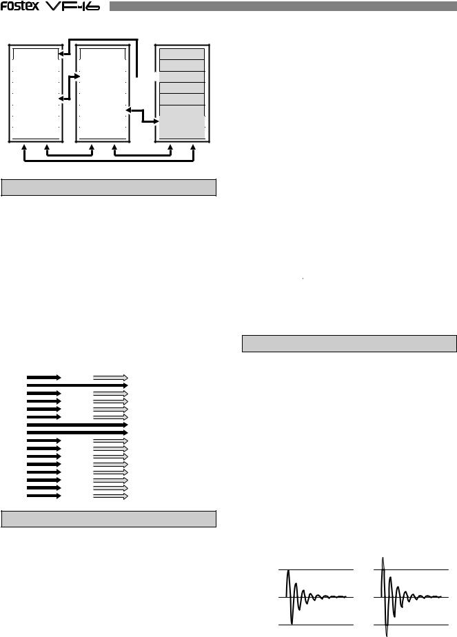
BUSS Recording
The second recording mode is the BUSS REC mode. This recording mode is mainly used to:
*Record sounds while applying equalizer and built-in effects; and
*Record (ping-pong recording, etc.) signals mixed on multiple channels on two or one track.
This mode is used to record signals sent to the REC BUSS, that is the recording buss, after the input signal or track play sound is processed through the mixer and level tuned or equalized. Built-in effect signals can also be sent to the REC BUSS, therefore, sounds applied with an effect can also be recorded.
The channels sent to REC BUSS are called SOURCE.
The REC BUSS comes with L/R 2-channels, therefore, it is possible to simultaneously BUSS REC either 2 or 1 track.
Playback sound
Playback sound
Input signal
|
|
|
MIXER |
|
|
|
|
|
|
|
CH STATUS |
ORANGE |
INPUT |
RED |
REC |
GREEN |
PLAY |
OFF |
MUTE |
|
|
|
|
|
CH STATUS/CH SEL |
|
|
|
|
|
|
|
|
|
|
|
|
|
|
|
|
EFF EDIT |
|
|
|
|
|
|
|
|
|
|
EFF1 |
EFF2 |
+6 |
+6 |
+6 |
+6 |
+6 |
+6 |
+6 |
+6 |
|
|
|
|
|
|
|
|
|
|
|
|
MUTE |
MUTE |
|
|
|
|
|
|
|
|
|
CH PARAM EDIT |
|
0 |
0 |
0 |
0 |
0 |
0 |
0 |
0 |
|
|
EQ/COMP |
|
EFF1/EFF2 |
HI-G/F/Q |
||||||||
|
|
|
|
|
|
|
|
|
PRE/POST |
COMP |
-10 |
-10 |
-10 |
-10 |
-10 |
-10 |
-10 |
-10 |
|
|
|
|
|
|
|
|
|
|
|
|
AUX1/AUX2 |
MID-G/F/Q |
-20 |
-20 |
-20 |
-20 |
-20 |
-20 |
-20 |
-20 |
|
|
|
-30 |
-30 |
-30 |
-30 |
-30 |
-30 |
-30 |
-30 |
|
PRE/POST |
|
-40 |
-40 |
-40 |
-40 |
-40 |
-40 |
-40 |
-40 |
|
|
|
-∞ |
-∞ |
-∞ |
-∞ |
-∞ |
-∞ |
-∞ |
-∞ |
|
PAN |
LO-G |
|
|
|
||||||||
|
|
|
|
|
|
|
|
|
FADER |
CH VIEW |
1 |
2 |
3 |
4 |
5 |
|
6 |
7 |
8 |
TRACK |
|
|
|
|
CH STATUS/CH SEL |
|
|
|
|
|
|
|
+6 |
+6 |
+6 |
+6 |
+6 |
+6 |
+6 |
+6 |
|
|
|
0 |
0 |
0 |
0 |
0 |
0 |
0 |
0 |
|
|
|
-10 |
-10 |
-10 |
-10 |
-10 |
-10 |
-10 |
-10 |
|
|
|
-20 |
-20 |
-20 |
-20 |
-20 |
-20 |
-20 |
-20 |
|
|
|
-30 |
-30 |
-30 |
-30 |
-30 |
-30 |
-30 |
-30 |
|
|
|
-40 |
-40 |
-40 |
-40 |
-40 |
-40 |
-40 |
-40 |
|
|
|
-∞ |
-∞ |
-∞ |
-∞ |
-∞ |
-∞ |
-∞ |
-∞ |
|
|
|
9 |
10 |
11 |
12 |
13 |
14 |
15 |
16 |
TRACK |
A |
B |
C |
D |
E |
F |
G |
H |
INPUT |
RECORDER |
REC BUSS |
|
|
|||||||||||||||||||||||||||||||||||||||||||||
1 ~ 16 Track |
|
|
|
L R |
|
|
||||||||||||||||||||||||||||||||||||||||||
Mix and record to 1 or 2 tracks |
|
|
|
|
|
|
|
|
|
|
|
|
|
|
|
|
|
|
|
|
|
|
|
|
|
|
|
|
|
|
|
|
|
|
||||||||||||||
|
|
|
|
|
|
|
|
|
|
|
|
|
|
|
|
|
|
|
|
|
|
|
|
|
|
|
|
|
|
|
|
|
|
|
|
|
|
|
|
|
|
|
|
|
|
|
|
|
|
|
|
|
|
|
|
|
|
|
|
|
|
|
|
|
|
|
|
|
|
|
|
|
|
|
|
|
|
|
|
|
|
|
|
|
|
|
|
|
|
|
|
|
|
|
|
|
|
|
|
|
|
|
|
|
|
|
|
|
|
|
|
|
|
|
|
|
|
|
|
|
|
|
|
|
|
|
|
|
|
|
|
|
|
|
|
|
|
|
|
|
|
|
|
|
|
|
|
|
|
|
|
|
|
|
|
|
|
|
|
|
|
|
|
|
|
|
|
|
|
|
|
|
|
|
|
|
|
|
|
|
|
|
|
|
|
|
|
|
|
|
|
|
|
|
|
|
|
|
|
|
|
|
|
|
|
|
|
|
|
|
|
|
|
|
|
|
|
|
|
|
|
|
|
|
|
|
|
|
|
|
|
|
|
|
|
|
|
|
|
|
|
|
|
|
1 |
3 |
5 |
7 |
9 |
11 |
13 |
15 |
2 |
4 |
6 |
8 |
10 |
12 |
14 |
16 |
7
The keys below play important roles when executing DIRECT recording or BUSS recording. Please learn their functions before operating the VF-16.
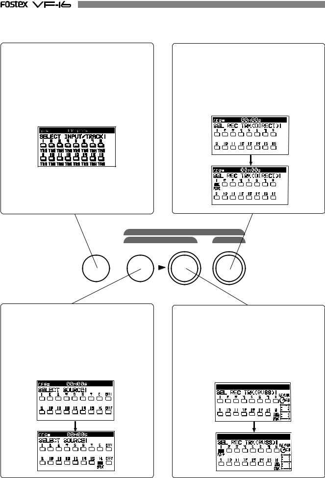
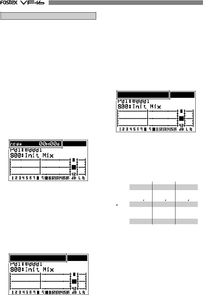
[INPUT SEL] key
This key is used to determine whether signals to be input to tracks Ch1-Ch16 should be the recorder output (TRACK) or the input signal (INPUT).
When this key is pressed, the display shown below will be shown to enable selection of "TRACK" or "INPUT." This display will always appear when the [INPUT SEL] key is pressed after switch ON of power to indicate that it is set for input of recorder output to Ch1-Ch16. DIRECT recording is normally executed under this setting.
The Ch9-Ch16 icons can be changed and when the [CH STATUS/CH SEL] key for these tracks are pressed, it will alternately switch between "TRK" and "INPUT." Signals applied to input connectors (A-H) will be routed to the channel switched to "INPUT."
[DIRECT-REC TRK] key
This key is used to setup the "recording track" for DIRECT recording. When this key is pressed, the display for selecting the DIRECT recording track will appear. If any one [CH STATUS/CH SEL] key is pressed while in this display, the track for DIRECT recording will enter the READY mode. The example display below shows track 1 set to READY and that sound sources input to inputs 1/9/A connectors can be DIRECT recorded in track 1.
REC ASSIGN |
|
BUSS |
DIRECT |
INPUT SEL SOURCE REC TRK REC TRK
[BUSS-SOURCE] key
This key is used to select the source channel for BUSS recording. The display shown below will appear when this key is pressed and the source channel can then be selected. If the [CH STATUS/CH SEL] key is pressed under this condition, that channel will be selected for the source channel and then BUSS recorded in the track selected with the [BUSS-REC TRK] key. The display below is indicating that the input H signal in Ch16 is set as the source channel.
[BUSS-REC TRK] key
This key is used to select the recording track at executing BUSS recording. When this key is pressed, the example shown below will be displayed and then the BUSS recording channel can be selected. If the desired [CH STATUS/CH SEL] key is pressed, that track will be selected for the recording track and be in the READY state. The example below indicates that the input H signal in Ch16 is selected as the source channel and set for BUSS recording in track 1.
8
RECORDING System
Unlike conventional systems, the VF-16 records on a hard disk storage device, instead of cassette tape. Sound source recording can start from any point on a formatted disk, as long as the point is within a 24 hour time range in ABS time. Note that it is also possible to move (locate) to any point within that time range, as well. Just think of the VF-16 as coming with a tape that is pre-programmed with a 24 hour counter.
ABS0 |
|
|
|
|
REC END |
23h 59m 59s |
||||
00m 00s |
05m 00s |
10m 00s |
15m 00s |
|||||||
|
|
|
|
|
|
|
|
...... |
|
|
|
|
|
|
|
|
|
|
|
|
|
|
recorded area |
unrecorded area |
recorded area |
unrecorded area |
|
|
||||
|
|
|
|
|||||||
|
|
|
|
|
|
|
|
|
|
|
You can record at any point within 24 hours in ABS time.
The REC time of cassette tape type recorders vary according to the REC time of the tape. Recording with the VF-16 is more efficient since unrecorded areas of the disk are not used although the REC time is not unlimited.
unrecorded |
5 minute recording 5 minute recording |
24 hour recording |
|||||
|
|
|
|
|
|
|
|
|
|
|
|
|
|
|
|
|
recorded area |
recorded area |
unrecorded area (remain) ...... |
|
|||
|
|
|
|
|
|
|
|
PROGRAM
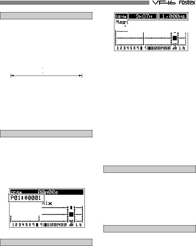
You can use up to a maximum of 99 “24-hour time counted tapes” with the VF-16. This tape is called a “Program”.
Note that a program exists individually on the hard disk. Therefore, each respective program can be freely recorded, played and edited without affecting other programs. A program can be named with a program title, making it easier to identify and file the musical piece. In the usual menu, the Program appears on the LCD as shown in the following Figure.
Program: P01 |
|
Title: |
#0001 |
REMAIN Indicator
The REMAIN indicator shows how much recording time is left on hard disk in use.
The VF-16 is controlled with a 24-hour clocked program. Note that the REC time varies according to how much space there is left on the hard disk.
By switching the LCD, the VF-16 remain display appears in the following manner, as shown in the figure below. The rough recordable time is on the hard disk is computed in terms of a mono-track basis. The value indicates the available recordable time and disk space when recording one mono track.
Remain Time |
Hard disk space |


 3h 07m


 1,000MB=1GB
A mono-track refers to one track. Therefore, a monotrack REMAIN time is the recordable length on the hard disk space available when recording only one track.
It is possible to compute the recordable time by dividing the REMAIN time with the number of tracks to record. Therefore, if four tracks are simultaneously recorded, then the recordable time is 46 minutes (3 hours 7 minutes divided by 4). If eight tracks are simultaneously recorded then the recordable time is 23 minutes (divided by 8), and for sixteen tracks the recordable time would be 12 minutes (divided by 16).
The VF-16 manages up to 99 programs on the hard disk. Note that the space on the hard disk is slightly reduced as the number of programs increase, since each program contains various settings, in addition to the REC data.
Therefore, it is important to always check the REMAIN time left prior to starting the recording, to ensure that you have enough hard disk space to work with.
A shortage of hard disk space will stop the recording.
CHANNEL and TRACK
According to this manual, “channel” refers to mixer items and “track” refers to recorder items.
For example, a sentence may read as follows.
“One track of recorder play music will be started on the channel 1 fader of the mixer.” “Eight channels worth of signals from input A to H will be recorded on tracks 7 and 8 of the recorder.”
ADDITIONAL TRACK
One program on the VF-16 consists of 24 tracks. The user can record, play and edit Tracks 1-16. There are also 8 additional tracks (17-24). These 24 tracks can be alternately exchanged in one track or an 8 track block. This is called track exchange. This makes it possible to record solo parts on several tracks, exchange the parts and compare the results. The rhythm section recorded on multiple tracks can also be completely exchanged and remixed with this feature, which is a convenience in numerous ways. Note that tracks 17-24 cannot be recorded, played or edited. They must be exchanged with tracks 1-16 to execute these features.
9
Track 1 |
Track 2 |
Track 3 |
Track 4 |
Track 5 |
Track 6 |
Track 7
Track 8
One track exchange
Track 9 |
Track 10 |
Track 11 |
Track 12 |
Track 13 |
Track 14 |
Track 15
Track 16
Track 17
Track 18

 Track 19
Track 20
Track 21
Track 22 |
Track 23 |
Track 24 |
8 track block exchange
INPUT Monitoring and PLAYBACK Monitoring
There are two ways to monitor the signal output (track sound) from each track with the VF-16 recorder: input monitoring and playback monitoring.
Playback monitoring means that the track output is the sound that is played. This feature is generally used to playback and listen to sounds that have already been recorded. Playback monitoring is generally used to playback sound.
Input monitoring means the signals (sounds to be recorded) input on that track are directly sent to the track output. This feature is used to check the REC level of the sound to record.
Therefore, tracks that are able to be input monitored are either in the “READY” or recording state.
Signal input in the recorder |
Signal output from the recorder |
|
|
1 track |
Playback sound (Playback monitor) |
|
2 track READY |
Input signal (Input monitor) |
|
3 track |
Playback sound (Playback monitor) |
|
4 track |
Playback sound (Playback monitor) |
|
5 track |
Playback sound (Playback monitor) |
|
||
|
6 track |
Playback sound (Playback monitor) |
|
7 track READY |
Input signal (Input monitor) |
|
8 track READY |
Input signal (Input monitor) |
|
9 track |
Playback sound (Playback monitor) |
|
10 track |
Playback sound (Playback monitor) |
|
||
|
11 track |
Playback sound (Playback monitor) |
|
12 track |
Playback sound (Playback monitor) |
|
||
|
13 track |
Playback sound (Playback monitor) |
|
14 track |
Playback sound (Playback monitor) |
|
15 track |
Playback sound (Playback monitor) |
|
||
|
16 track |
Playback sound (Playback monitor) |
EVENT
When recording with the VF-16, an independent audio file for each recording is respectively created on the tracks recorded. Remember that silence is also recognized as one 0 file. These audio files and 0 (silent) files are called an “events”. A total of 512 events can be created for each track with the VF-16. An excess of 512 events cannot be recorded. It is rare that this happens in normal use. The VF-16 is also complete with the function to indicate the current number of events. An alarm will sound when exceeding the maximum number of events authorized. This problem can be resolved by saving or loading the program (procedures described later) in such case. The following are specific examples of the number of events.
A.The VF-16 counts the silent portion of a silent track, which is counted as one file, but not recorded with any sound. Therefore, this means that there will be one file on the track.
B.One audio file is created when recording sound on a track. Therefore, this means that there will be two files on the track.
C.A new audio file is created when consecutively recording. Therefore, this means that there will be three files on the track.
D.An audio files is created after a 0 file, when re-recording after fast forward. Therefore, this means that there will be five files on the track.
E.When straddling (b) and (c) to record, the track will have four files, and thus, the number of events are reduced.
A |
|
|
Silence |
|
|
|
|
|
|
|
|
|
|
|
|
|
|
|
|
|
|
|
|
|
|
|
B |
Rec B |
|
|
|
Silence |
|
|
|
|
|
|
|
|
|
|
|
|
C |
Rec B |
|
Rec C |
|
|
|
Silence |
|
|
|
|
|
|
|
|
|
|
D |
Rec B |
|
Rec C |
|
Silence |
|
Rec D |
Silence |
|
|
|
|
|
|
|
||
E |
Rec E |
|
|
Silence |
|
Rec D |
Silence |
|
|
|
|
|
|
|
|
|
|
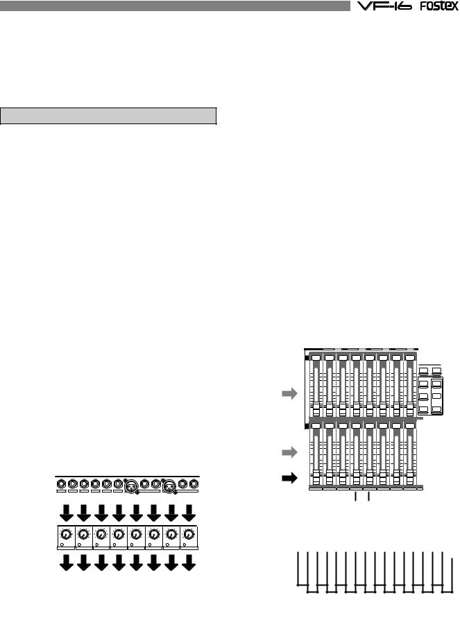
TRIM
It is important to take care when analog signals input are converted into digital signals (A/D conversion) when recording with the VF-16.
TRIM is used to tune this process and the PEAK LED is used to monitor the process.
If the trim gain is too high ([PEAK] LED illuminated) for the analog signals input into [INPUT] A to H, then the signals input will be converted into distorted (clipped) digital signals, which will sound like noise. Once converted with this noise, it is not possible to eliminate this distortion from the sound with the mixer or recorder. Therefore, it is important to tune the [TRIM] to a level where the “[PEAK] LED fluctuates between the illuminating or not” point at the maximum volume of the signal input.
Appropriate gain |
Excessive gain |
Clip level
Clip level
10
FADER
The VF-16 features 16 channel faders and 1 master fader. Among the faders, the faders for channels 1 to 8 are always started up with output signals from the recorder of tracks 1 to 8 (PLAYBACK or INPUT Monitoring) to adjust this level. The master fader is always used to adjust the output level of the stereo output.
“Signals input from A to H” or “signals output from the recorder” can be selected as signals to fade and the fade level can be adjusted with faders for channels 9 to 16.
This is a way to easily record with the minimum faders along with the earlier mentioned “2 recording modes.”
It is not possible to mix the playback sound of tracks 9 to 16 if inputs A to H are started for all channel faders of 9 to 16. However, this can be prevented, since during normal use, the number of signals input are reduced when recording to tracks 9 to 16 (leaving only the solo part, etc.).
CH STATUS |
ORANGE |
INPUT |
|
RED |
REC |
GREEN |
PLAY |
OFF |
MUTE |
|
|
|
|
|
|
|
|
CH STATUS/CH SEL |
|
|
|
|
SCENE |
||
|
|
|
|
|
|
|
|
|
|
|
RECALL |
STORE |
|
|
|
|
|
|
|
|
|
|
|
DIRECTRCL |
MAP |
|
|
|
|
|
|
|
|
|
|
|
CLEAR |
|
|
|
|
|
|
|
|
|
|
|
|
EFF EDIT |
|
|
|
|
|
|
|
|
|
|
|
|
EFF1 |
EFF2 |
+6 |
+6 |
|
+6 |
|
+6 |
+6 |
+6 |
|
+6 |
+6 |
|
|
|
|
[CH STATUS/CH SEL] key |
|
MUTE |
MUTE |
|||||||
|
|
|
|
|
|
|
|
|
|
|
CH PARAM EDIT |
|
0 |
0 |
|
0 |
|
0 |
0 |
0 |
|
0 |
0 |
|
EQ/COMP |
|
|
|
EFF1/EFF2 |
HI-G/F/Q |
||||||||
|
|
|
|
Channels 1 to 8 |
|
|
||||||
|
|
|
|
|
|
|
|
|||||
|
|
|
|
|
Channel fader |
|
|
|
PRE/POST |
COMP |
||
|
|
|
|
|
|
|
|
|
|
|||
-10 |
-10 |
|
-10 |
|
-10 |
-10 |
-10 |
|
-10 |
-10 |
|
|
|
|
|
|
|
|
|
|
|
|
|
AUX1/AUX2 |
MID-G/F/Q |
-20 |
-20 |
|
-20 |
|
-20 |
-20 |
-20 |
|
-20 |
-20 |
|
|
-30 |
-30 |
|
-30 |
|
-30 |
-30 |
-30 |
|
-30 |
-30 |
PRE/POST |
|
-40 |
-40 |
|
-40 |
|
-40 |
-40 |
-40 |
|
-40 |
-40 |
|
|
-∞ |
-∞ |
|
-∞ |
|
-∞ |
-∞ |
-∞ |
|
-∞ |
-∞ |
PAN |
LO-G |
|
|
|
|
|
||||||||
|
|
|
|
|
|
|
|
|
|
|
FADER |
CH VIEW |
1 |
|
2 |
|
3 |
4 |
5 |
|
6 |
7 |
8 |
TRACK |
|
|
|
|
|
|
CH STATUS/CH SEL |
|
|
|
|
|
|
|
+6 |
+6 |
[CH STATUS/CH SEL] key |
+6 |
+6 |
|
|
|
|
||||||||||||||||||||||||||||||||||||
|
|
|
|
|||||||||||||||||||||||||||||||||||||||||
+6 |
+6 |
+6 |
+6 |
|
|
+6 |
|
|
|
|
|
|
||||||||||||||||||||||||||||||||
0 |
0 |
0 |
0 |
0 |
0 |
|
|
0 |
|
|
0 |
|
|
Master0 fader |
||||||||||||||||||||||||||||||
|
|
|
|
|
|
|
|
|
|
|
Channels 9 to 16 |
|
|
|
|
|
|
|
|
|
|
|
|
|
|
|
|
|
||||||||||||||||
|
|
|
|
|
|
|
|
|
|
|
|
Channel fader |
|
|
|
|
|
|
|
|
|
|
|
|
|
|
|
|
|
|||||||||||||||
-10 |
-10 |
-10 |
-10 |
-10 |
-10 |
|
|
-10 |
|
|
-10 |
-10 |
|
|
|
|
||||||||||||||||||||||||||||
|
|
|
|
|
|
|
|
|
|
|
|
|
|
|
|
|
|
|
|
|
|
|
|
|
|
|
|
|
|
|
|
|
|
|
|
|
|
|
|
|
|
|
|
|
-20 |
|
|
|
-20 |
|
|
|
|
-20 |
|
|
|
-20 |
|
|
|
-20 |
|
|
|
-20 |
|
|
|
-20 |
|
|
|
-20 |
|
|
|
|
-20 |
|
|
|
|
||||||
-30 |
|
|
|
-30 |
|
|
|
|
-30 |
|
|
|
-30 |
|
|
|
-30 |
|
|
|
-30 |
|
|
|
-30 |
|
|
|
-30 |
|
|
|
|
-30 |
|
|
|
|
||||||
-40 |
|
-40 |
|
-40 |
|
-40 |
|
-40 |
|
-40 |
|
|
-40 |
|
|
-40 |
|
-40 |
|
|
|
|
||||||||||||||||||||||
|
|
|
|
|
|
|
|
|
|
|
|
|
|
|
|
|
|
|
|
|
|
|
|
|
|
|
|
|
|
|
|
|
|
|
|
|
|
|
|
|
|
|
|
|
-∞ |
|
|
|
|
-∞ |
|
|
|
|
-∞ |
|
|
|
|
-∞ |
|
|
|
|
-∞ |
|
|
|
|
-∞ |
|
|
|
|
-∞ |
|
|
|
|
-∞ |
|
|
|
|
-∞ |
|
|
|
|
9 |
10 |
11 |
12 |
13 |
14 |
15 |
16 |
TRACK MASTER |
A |
B |
C |
D |
E |
F |
G |
H |
INPUT |
[CH STATUS/CH SEL] Key
The [CH STATUS/CH SEL] Key is the most important key when operating the VF-16.
The status and contents of operation varies according to selections made with this key.
*Under normal conditions, the key illuminates or flashes to indicate that the signal is input “INPUT” into the current channel fader, the playback sound “TRACK” is started, or the track is ready to record (READY). This key also functions as the fader ON/ OFF (Mute) key. In this case the key is not lit.
CH STATUS |
ORANGE |
INPUT |
RED |
REC |
GREEN |
PLAY |
OFF |
MUTE |
|
|
|
CH STATUS/CH SEL |
|
|
|
|
|
+6 |
+6 |
+6 |
+6 |
+6 |
+6 |
+6 |
|
+6 |
0 |
0 |
0 |
0 |
0 |
0 |
0 |
|
0 |
*To set the send level to the built-in effect or set the equalizer settings of each channel, press the keys to set each parameter shown in the figure below and then press the [CH STATUS/CH SEL] key to select the channel to set.
It is possible, for example, to set the PAN of one channel signal when the channel 1 [CH STATUS/CH SEL] key is pressed after pressing the [PAN] key. All channels can be set by pressing the [CH STATUS/CH SEL] key of channels 1 to 16.
CH PARAM EDIT
EQ/COMP
EFF1/EFF2 HI-G/F/Q
PRE/POST COMP
AUX1/AUX2 MID-G/F/Q
PRE/POST |
|
PAN |
LO-G |
FADER |
CH VIEW |
*When the [CH STATUS/CH SEL] key is pressed, the status will require selection of either “INPUT” or “TRACK” for channel faders 9 to 16, as mentioned earlier. Therefore, operate only the [CH STATUS/CH SEL] key of channels 9 to 16 to switch between “INPUT” or “TRACK,” each time the key is pressed.
*When pressing the [BUSS-SOURCE] key, the status will require selection of a channel to send to “REC BUSS”, as mentioned earlier. Therefore, the channel in which the [CH STATUS/CH SEL] key is pressed is sent to the “REC BUSS”.
All channels are selected up to this point. The following two types only select tracks.
*It is possible to select the track to record (REC READY) in each respective REC mode by pressing the [BUSS-REC TRK] key and [DIRECT-REC TRK] key.
REC ASSIGN |
|
BUSS |
DIRECT |
INPUT SEL SOURCE REC TRK REC TRK
11
TIME BASE
The term “Time Base” frequently appears in the text of this manual. The time base plays the same role as the “tape counter” of conventional tape recorders, and is used to show the location of the recorder.
There are 3 types of time bases:
1.ABS (Absolute Time) indication
2.BAR/BEAT/CLK (Bar, Beat, Clock) indication
3.MTC (MIDI Time Code)
The user can switch between time bases by pressing the [DISP SEL/TIME BASE] key, while the [SHIFT] key is depressed.
An ABS (Absolute Time) base is the “absolute time” of the hard disk. A time base counter between 00H 00M 00S (ABS 0) and 23H 59M 59S is created when creating a program. According to the following figure, the recorder is located at a 00M (minute) 00S (second) ABS point. The H (hour) appears when the ABS exceeds the one hour mark.
ABS 0 is the universal standard point to manage the recorder location, and correlates with other time bases.
BAR/BEAT/CLK indicate the “Bar, Beat, Clock” that are created with the tempo map (beat and tempo) of the VF-16.
According to the following figure, the recorder is located at -002BAR (Bar 2) 1BEAT (Beat 1) of the BAR/ BEAT/CLK.
BAR/BEAT/CLK set the ABS 0 location as Bar -002 as the offset position.
The location of the bar thereafter is determined according to the beat and tempo setting.
The default setting of ABS 0 is set at Bar -002, however, this setting is variable between Bars -009 and -002.
MTC set the ABS 0 location to MTC ** H** M**S. In other words, MTC sets the time base to start MTC from a certain time, which serves as the offset time, to synchronize the following 24 hour MTC time base with the ABS to count the time. If, for example, ABS 0 is set to MTC 1H, then MTC starts from 1H and ABS 1H (one hour elapsed) will be MTC 2H.
The MTC time set as ABS 0 is called the “MTC Offset”. According to the figure below, the current location of the recorder is at MTC 00H (hour), 59M (minutes), 57S (seconds).
The default setting of the MTC offset is set to 00H 59M 57S 00F 00SF. This time base can be changed to any 24 hour clock.
It is also possible to change the setting to Bar 001 and Beat 1 of BAR/BEAT/CLK, instead of using the ABS 0 location point.
The following illustrates the relationship between the 3 time bases.
ABS 0
|
|
|
00M 00S |
00M 03S |
00M 06S |
|
|
|
ABS |
|
|
..... |
|
|
|
|
|
|
|
|
|
|
|
- 002BAR 1 |
001BAR 1 |
002BAR 1 |
|
BAR/ |
|
/CLK |
|
|
..... |
|
|
|
|
||||
|
|
|
||||
|
|
|
|
|
|
|
|
|
|
00H 59M 57S |
01H 00M 00S |
01H 00M 03S |
|
|
|
MTC |
|
|
..... |
|
|
|
|
|
|
|
|
12

Names and Functions
INPUT MON OUT PHONES
1/9/A |
2/10/B |
3/11/C |
4/12/D |
5/13/E |
6/14/F |
|
7/15/G |
|
|
|
8/16/H |
L |
R |
|
|
|
|
|
|
|
BAL |
UNBAL |
INSERT |
BAL |
|
UNBAL |
INSERT |
|
|
|
|
|
|
TRIM |
|
|
|
|
MON OUT |
PHONES |
|
|||
LINE |
MIC LINE MIC LINE MIC |
LINE MIC |
LINE MIC |
LINE MIC |
LINE MIC |
LINE |
MIC |
0 10 |
0 |
10 |
DIGITAL |
|||
MULTITRACKER |
||||||||||||||
PEAK |
PEAK |
PEAK |
PEAK |
PEAK |
PEAK |
PEAK |
PEAK |
|
|
|
||||
|
|
|
|
|||||||||||
1/9/A |
2/10/B |
3/11/C |
4/12/D |
5/13/E |
6/14/F |
7/15/G |
8/16/H |
|
|
|
|
|
|
|
|
|
|
||
CH STATUS |
ORANGE |
INPUT |
RED |
REC |
GREEN |
PLAY |
OFF |
MUTE |
|
|
|
|
|
|
|
|
|
|
|
|
|
|
CH STATUS/CH SEL |
|
|
|
|
SCENE |
|
|
|
|
|
|
|
|
|||
|
|
|
|
|
|
|
|
|
|
RECALL |
STORE |
|
|
|
|
|
|
|
|
|
|
|
|
|
|
|
|
|
|
|
|
OPTICAL |
|
|
|
|
|
|
|
|
|
|
|
|
|
|
|
|
|
DIRECT RCL |
MAP |
|
|
|
|
|
|
|
|
|
|
|
|
|
|
|
|
|
|
CLEAR |
|
|
|
|
|
|
|
|
|
|
|
|
|
|
|
|
|
|
|
EFF EDIT |
|
|
|
|
|
|
|
|
|
|
|
|
|
|
|
|
|
|
|
EFF1 |
EFF2 |
|
|
|
|
|
|
|
|
+6 |
+6 |
+6 |
+6 |
|
+6 |
+6 |
|
+6 |
+6 |
|
|
ACCESS |
|
|
|
|
|
|
|
|
|
MUTE |
MUTE |
|
|
|
|
|
|
|
|
||||||||
|
|
|
|
|
|
|
|
|
|
|
|
|
|
|
|
|
|
||
|
|
|
|
|
|
|
|
|
|
CH PARAM EDIT |
PHANTOM |
|
|
|
|
|
|
|
|
0 |
0 |
0 |
0 |
|
0 |
0 |
|
0 |
0 |
|
EQ/COMP |
|
|
|
|
|
|
|
|
|
|
EFF1/EFF2 |
HI-G/F/Q |
|
|
|
|
|
|
|
|
||||||||
|
|
|
|
|
|
|
|
|
|
|
|
|
|
|
|
|
|
||
|
|
|
|
|
|
|
|
|
|
PRE/POST |
COMP |
|
REC ASSIGN |
|
|
|
|
|
|
-10 |
-10 |
-10 |
-10 |
|
-10 |
-10 |
|
-10 |
-10 |
|
|
BUSS |
DIRECT |
|
|
|
|
|
|
|
|
|
INPUT SEL |
SOURCE |
REC TRK |
REC TRK |
|
|
DISP SEL PGM SEL |
SETUP |
|||||||||
|
|
|
|
|
|
|
|
|
|
AUX1/AUX2 |
MID-G/F/Q |
|
|
|
|
|
|
|
|
-20 |
-20 |
-20 |
-20 |
|
-20 |
-20 |
|
-20 |
-20 |
|
|
|
|
|
|
|
|
|
|
-30 |
-30 |
-30 |
-30 |
|
-30 |
-30 |
|
-30 |
-30 |
PRE/POST |
|
AUTO RTN |
|
|
|
TIME BASE |
|
|
|
|
|
|
AUTO PUNCH |
|
|
CLIPBOARD |
|
A RTN |
|||||||||||
|
|
|
|
|
|
|
|
|
|
|
|
|
|
|
|||||
-40 |
-40 |
-40 |
-40 |
|
-40 |
-40 |
|
-40 |
-40 |
|
START |
IN |
OUT |
END |
IN |
|
ALIGN SEL |
OUT |
A PLAY |
-∞ |
-∞ |
-∞ |
-∞ |
|
-∞ |
-∞ |
|
-∞ |
-∞ |
PAN |
LO-G |
|
|
|
|
|
|
|
|
|
|
|
1 |
2 |
3 |
4 |
|
5 |
6 |
7 |
|
||||||||
|
|
|
|
|
|
|
|
|
|
|
|
|
|
MARK |
|
|
|
|
SCENE SEQ. |
|
|
|
|
|
|
|
|
|
|
FADER |
CH VIEW |
|
|
UNDO/ |
|
|
VARI |
|
|
|
|
|
|
|
|
|
|
|
|
|
HOLD/ |
STORE |
EDIT |
REDO |
|
|
PITCH |
LOCATE |
SCRUB |
1 |
2 |
3 |
|
4 |
5 |
|
6 |
7 |
8 |
TRACK |
|
|
|
|
|
|
|
|
|
|
|
|
CH STATUS/CH SEL |
|
|
|
|
|
|
|
|
|
|
|
|
|
|
||
|
|
|
|
|
|
|
|
|
|
|
|
|
|
|
|
|
P.EDIT |
EVT MEM |
|
|
|
|
|
|
|
|
|
|
|
|
RECORD |
STOP |
PLAY |
|
|
REWIND |
F FWD |
||
|
|
|
|
|
|
|
|
|
Top Panel |
AUTO PUNCH |
CLIPBOARD PLAY |
PREV |
NEXT |
||
|
|
|
|
|
|
|
|
|
|
|
|
|
LOCATE ABS 0 |
|
|
+6 |
+6 |
+6 |
+6 |
+6 |
+6 |
|
+6 |
|
+6 |
|
+6 |
|
LOCATE REC END |
|
|
|
|
|
|
|
|
Analog Input/Output Section |
|
|
JOG |
|
|||||
0 |
0 |
0 |
0 |
0 |
0 |
|
0 |
|
0 |
|
0 |
|
|
SHUTTLE |
|
|
|
|
|
|
|
|
|
Mixer Section |
FADER |
|
|
|
|||
|
|
|
|
|
|
|
|
Recorder Section |
ADJUST |
EXIT/NO |
|
|
|||
-10 |
-10 |
-10 |
-10 |
-10 |
-10 |
|
-10 |
|
|
|
|
||||
|
|
-10 |
|
-10 |
|
|
|
|
|||||||
|
|
|
|
|
|
|
|
|
|
|
|
LEVEL |
EJECT |
|
|
-20 |
-20 |
-20 |
-20 |
-20 |
-20 |
|
-20 |
|
-20 |
|
-20 |
ADJUST |
|
|
|
|
|
|
|
|
|
|
|||||||||
|
|
|
|
|
|
|
|
Display Section |
|
ENTER/YES |
|
|
|||
-30 |
-30 |
-30 |
-30 |
-30 |
-30 |
|
-30 |
|
-30 |
|
-30 |
|
|
|
|
-40 |
-40 |
-40 |
-40 |
-40 |
-40 |
|
-40 |
|
-40 |
|
-40 |
|
|
|
|
-∞ |
-∞ |
-∞ |
-∞ |
-∞ |
-∞ |
|
-∞ |
|
-∞ |
|
-∞ |
SHIFT |
|
|
|
9 |
10 |
11 |
12 |
13 |
|
14 |
|
15 |
16 |
TRACK |
MASTER |
|
|
|
|
A |
B |
C |
D |
E |
|
F |
|
G |
H |
INPUT |
|
|
|
|
|
|
|
|
|
|
|
|
|||||||||
Rear Panel
CAUTION |
WARNING: |
RISK OF ELECTRIC SHOCK |
TO REDUCE THE RISK OF FIRE OR ELECTRIC |
DO NOT OPEN |
SHOCK, DO NOT EXPOSE THIS EQUIPMENT |
AVIS: RISQUE DE CHOC ELECTRIQUE NE PAS OUVRIR |
TO RAIN OR MOISTURE. |
DIGITAL
MULTITRACKER
AUX SEND |
ST OUT |
MIDI |
DIGITAL / DATA |
FOOT SW |
SCSI |
POWER |
AC-IN |
|
IN |
OUT |
|
R |
L |
IN |
OUT |
*1. All keys on the panel will be indicated with a [ ] around the name in this manual. Example: [PLAY] key, [INPUT] terminal, etc.
*2. All keys that require the [SHIFT] key to be depressed to take effect will be underlined. Example: [EFF EDIT-EFF1/MUTE] key, etc.
*3. Channel is represented as “ch” and track as “trk” according to the contents. Example: ch1 fader, trk16, etc.
13
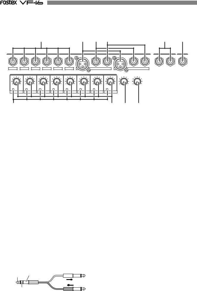
Top Panel
Analog Input/Output Section
1 |
2 |
3 |
4 |
INPUT
1/9/A |
2/10/B |
3/11/C |
4/12/D |
5/13/E |
6/14/F |
7/15/G |
|
8/16/H |
|
|
|
|
|
|
BAL |
UNBAL |
INSERT BAL |
UNBAL |
INSERT |
|
|
|
|
TRIM |
|
|
MON OUT PHONES |
||
LINE MIC |
LINE MIC |
LINE MIC |
LINE MIC |
LINE MIC |
LINE MIC |
LINE MIC |
LINE MIC |
0 |
10 |
0 |
10 |
PEAK |
PEAK |
PEAK |
PEAK |
PEAK |
PEAK |
PEAK |
PEAK |
|
|
|
|
1/9/A |
2/10/B |
3/11/C |
4/12/D |
5/13/E |
6/14/F |
7/15/G |
8/16/H |
|
|
|
|
7 |
8 |
9 |
10 |
5 |
6 |
MON OUT |
PHONES |
L |
R |
1. [INPUT] (Unbalanced) Jack: A to F
*This adjusts the unbalanced output of the external sound source.
*Standard Input Level: -50dBV to + 2dBV
*Connector: Phones jack
5. [MON OUT] (Monitor Output) Jack: L, R
*Connect a speaker with internal amp or amp + speaker for monitoring purposes.
*Standard Output Level: -10dBV
*Connector: Phones jack
2. [INPUT BAL] (Balanced) Jack: G, H
*Connect to the balanced output of the external sound source.
*Standard Input Level: -50dBV to + 2dBV (approx. -48dBu to +4dBu)
*Connector: XLR-3-31 type (No. 2 Hot)
*Phantom power (+48V) for condenser mics.
*This input is disconnected when [INPUT UNBAL] jacks G and H are plugged.
3. [INPUT UNBAL] (Unbalanced) Jack: G, H
*Connections with unbalanced output from external sound source.
*Standard Input Level: -50dBV to + 2dBV
*Connector: Phones jack
*[INPUT UNBAL] jacks G and H are disconnected when this input is plugged.
4. [INSERT] Jack: G, H
*External effector (generally a compressor/limiter, etc.) only used for G and H channel input is connected.
*Standard Input/Output Level: -10dBV
*Use a Y-cable, as shown below, to connect an external effector since the ø6 TRS phones jack is used.
TIP: |
To Effect Input |
SEND GND |
|
RING: |
|
RETURN |
From Effect Output |
6. [PHONES] (Headphones) Jack
*Headphones connection for monitoring purposes.
*Connector: TRS Phones jack
7. [PEAK] LED: 1 to 8
*Lights ON if the input signal is approx. 2dB lower than the clipping level.
*Tune the [TRIM] knob whether to light ON or OFF the LED for the gain.
8. [TRIM] Knob: 1 to 8
*Adjusts the gain according to the input signal.
*Gain is adjustable between -50dBV (MIC) and +2dBV (LINE).
9. [MON OUT] (Monitor Output) Knob
* Adjusts the output level from the [MON OUT] jack.
10. [PHONES] (Headphones) Knob
* Adjusts the output level form the [PHONES] jack.
For more details, refer to the respective instructions of each item.
14
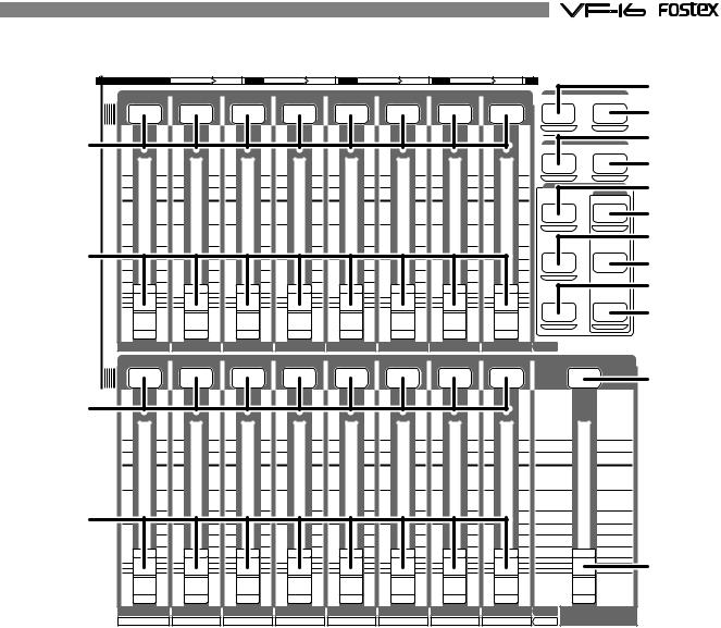
Mixer Section
CH STATUS |
ORANGE |
INPUT |
RED |
REC |
GREEN |
PLAY |
OFF |
MUTE |
|
|
|
|
|
CH STATUS/CH SEL |
|
|
|
|
SCENE |
||
|
|
|
|
|
|
|
|
|
RECALL |
STORE |
11 |
|
|
|
|
|
|
|
|
DIRECT RCL |
MAP |
|
|
|
|
|
|
|
|
CLEAR |
||
|
|
|
|
|
|
|
|
EFF EDIT |
||
|
|
|
|
|
|
|
|
|
EFF1 |
EFF2 |
+6 |
+6 |
+6 |
+6 |
+6 |
+6 |
+6 |
+6 |
|
MUTE |
MUTE |
|
|
|
|
|
|
|
|
|
||
|
|
|
|
|
|
|
|
|
CH PARAM EDIT |
|
0 |
0 |
0 |
0 |
0 |
0 |
0 |
0 |
|
|
EQ/COMP |
|
EFF1/EFF2 |
HI-G/F/Q |
||||||||
|
|
|
|
|
|
|
|
|
||
|
|
|
|
|
|
|
|
|
PRE/POST |
COMP |
-10 |
-10 |
-10 |
-10 |
-10 |
-10 |
-10 |
-10 |
|
|
|
12 |
|
|
|
|
|
|
|
|
AUX1/AUX2 |
MID-G/F/Q |
-20 |
-20 |
-20 |
-20 |
-20 |
-20 |
-20 |
-20 |
|
|
|
-30 |
-30 |
-30 |
-30 |
-30 |
-30 |
-30 |
-30 |
|
PRE/POST |
|
-40 |
-40 |
-40 |
-40 |
-40 |
-40 |
-40 |
-40 |
|
|
|
-∞ |
-∞ |
-∞ |
-∞ |
-∞ |
-∞ |
-∞ |
-∞ |
|
PAN |
LO-G |
|
|
|
||||||||
|
|
|
|
|
|
|
|
|
FADER |
CH VIEW |
1 |
2 |
3 |
4 |
5 |
|
6 |
7 |
8 |
TRACK |
|
|
|
|
CH STATUS/CH SEL |
|
|
|
|
|
|
|
11 |
|
|
|
|
|
|
|
|
|
|
+6 |
+6 |
+6 |
+6 |
+6 |
+6 |
+6 |
+6 |
|
+6 |
|
0 |
0 |
0 |
0 |
0 |
0 |
0 |
0 |
|
0 |
|
-10 |
-10 |
-10 |
-10 |
-10 |
-10 |
-10 |
-10 |
|
-10 |
|
12 |
|
|
|
|
|
|
|
|
|
|
-20 |
-20 |
-20 |
-20 |
-20 |
-20 |
-20 |
-20 |
|
-20 |
|
-30 |
-30 |
-30 |
-30 |
-30 |
-30 |
-30 |
-30 |
|
-30 |
|
-40 |
-40 |
-40 |
-40 |
-40 |
-40 |
-40 |
-40 |
|
-40 |
|
-∞ |
-∞ |
-∞ |
-∞ |
-∞ |
-∞ |
-∞ |
-∞ |
|
-∞ |
|
9 |
10 |
11 |
12 |
13 |
14 |
15 |
16 |
TRACK |
MASTER |
|
A |
B |
C |
D |
E |
F |
G |
H |
INPUT |
||
|
13
14
15
16
17
18
19
20
21
22
23
24
11. [CH STATUS/CH SEL] Key: channels 1-16
*ON/OFF key for each channel during normal display (explained later).
*Select the channel to CHECK/CHANGE the setting with ([CH PARAM EDIT] Key (No. 17-22) when CHECKING/ CHANGING various PAN, equalizer and other mixer parameters.
*Select the recorder track (1-16) for REC READY or REC CANCEL (SAFE) status (flashing [REC ASSIGN-DIRECT] key or [REC ASSIGN-BUSS] key]) when selecting the track to record.
*The flashing key illustrates the following STATUS:
[ORANGE]: |
The level of the input signals [INPUT] into input |
|
Ato H are adjustable. Only channels 9-16 are |
|
adjustable with the fader. |
[GREEN]: |
The level of the audio [TRACK (PLAY)] on the |
|
track are adjustable with the fader. |
[OFF]: |
The signals to the fader are [MUTE] (no |
|
sound). |
[RED]: |
The corresponding tracks (1-16) are READY |
|
(to record). The [GREEN] and [RED] key will |
|
alternately flash. The light will remain ON |
|
during the recording process. |
12. Channel Fader: channels 1-16
*The 1-8 channel faders are used to adjust the audio level [TRACK] of tracks 1-8.
*The 9-16 channel faders are used to adjust the sound level of signals input into A to H or audio levels [TRACK] of 9-16. Use the [INPUT SEL] key to choose which level to adjust.
13. [SCENE-RECALL/DIRECT RCL] Key
*This is used to recall the scene memory.
*Press this key while the [SHIFT] key is depressed for direct scene memory recall.
*Simultaneously press this key and the [SCENE-STORE/ MAP] key to erase the scene memory.
14. [SCENE-STORE/MAP] Key
*This is used to store scene memory.
*Press this key while the [SHIFT] key is depressed to CHECK/CHANGE the scene map.
*Simultaneously press this key and the [SCENERECALL/DIRECT RCL] key to erase the scene memory.
15

15. [EFF EDIT-EFF1/MUTE] Key
*This is used to CHECK/CHANGE the EFFECT type and parameter settings of EFFECT 1.
*Press this key while the [SHIFT] key is depressed to turn ON/OFF the mute feature of EFFECT 1.
16. [EFF EDIT-EFF2/MUTE] Key
*This is used to CHECK/CHANGE the effect type and parameter settings of EFFECT 2.
*Press this key while the [SHIFT] key is depressed to turn ON/OFF the mute feature of EFFECT 2.
17. [CH PARAM EDIT-EFF1/EFF2/PRE/POST] Key
*This is used to CHECK/CHANGE the send level settings of EFFECT 1 or EFFECT2. The EFFECT 1 and EFFECT 2 settings alternate every time the key is pressed.
*Press this key while the [SHIFT] key is depressed to CHECK/CHANGE the PRE/POST settings of EFFECT1 or EFFECT 2.
*Use the [CH STATUS/CH SEL] Key to select the channel to change any settings together.
18. [CH PARAM EDIT-EQ/COMP-HI/G/F/Q/COMP] Key
*This is used to CHECK/CHANGE the high frequency parametric equalizer settings. The parameter settings alternate every time the key is pressed.
*Press this key while the [SHIFT] key is depressed to CHECK/CHANGE the COMPRESSOR settings.
*Use the [CH STATUS/CH SEL] Key to select the channel to CHECK/CHANGE any settings together.
19. [CH PARAM EDIT-AUX1/AUX2/PRE/POST] Key
*This is used to CHECK/CHANGE the send level settings of AUX 1 or AUX 2. The AUX 1 and AUX 2 settings alternate every time the key is pressed.
*Press this key while the [SHIFT] key is depressed to CHECK/CHANGE the PRE/POST settings of AUX 1 or AUX 2.
*Use the [CH STATUS/CH SEL] Key to select the channel to change any settings together.
20. [CH PARAM EDIT-EQ/COMP-MID-G/F/Q] Key
*This is used to CHECK/CHANGE the midrange frequencies of the parametric equalizer settings.
*Press this key while the [SHIFT] key is depressed to CHECK/CHANGE the settings.
21. [CH PARAM EDIT-PAN/FADER] Key
*This is used to CHECK/CHANGE the PAN settings.
*Press this key while the [SHIFT] key is depressed to show the current fader location. Finer level adjustment is possible by using the [JOG] dial.
*Use the [CH STATUS/CH SEL] key to select the channel to change any settings together.
22. [CH PARAM EDIT-EQ/COMP-LO-G/CH VIEW] Key
*This is used to CHECK/CHANGE the low frequencies of the parametric equalizer settings.
*Press this key while the [SHIFT] key is depressed to show the settings of the selected channel.
*Use the [CH STATUS/CH SEL] key to select the channel to change any settings together.
23. [MASTER CH STATUS/CH SEL] Key
*This becomes the master channel ON/OFF key when the LCD is in the normal display mode (described later).
*Select the channel to CHECK/CHANGE any settings with the ([CH PARAM EDIT] Key (No. 17-22)] to CHECK/CHANGE any PAN, equalizer or other mixer settings.
*The STATUS of the key lights ON are defined below.
[GREEN]: |
The level of the stereo buss L, R outputs are |
|
adjustable with the fader. |
[OFF]: |
The signals to the master fader are [MUTE] |
|
(no sound). |
24. [MASTER] Fader
*This is used to adjust the master level of the sound signals output from the STEREO OUT L, R jacks.
For more details, refer to the respective instructions of each item.
16
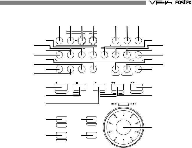
Recorder Section
25 26 27 28 |
29 30 31 |
|
|
|
|
REC ASSIGN |
|
|
|
|
|
|
|
|
|
|
|
BUSS |
DIRECT |
|
|
|
|
|
|
|
|
35 |
INPUT SEL |
SOURCE |
REC TRK REC TRK |
|
DISP SEL PGM SEL SETUP |
36 |
|
|||||
|
|
|
|
|
|
|
|
|
|
|
||
32 33 |
1 |
|
AUTO RTN |
3 |
4 |
5 |
TIMEBASE |
7 |
|
38 |
39 |
|
|
2 |
|
6 |
A RTN |
||||||||
34 |
|
|
AUTO PUNCH |
|
|
CLIPBOARD |
|
|
37 |
|||
|
START |
|
IN |
OUT |
END |
IN |
|
ALIGN SEL |
OUT |
A PLAY |
|
|
42 40 |
|
|
|
|
MARK |
|
|
|
|
SCENESEQ. |
46 45 |
|
|
|
|
|
UNDO/ |
|
|
VARI |
|
|
|||
43 |
HOLD/ |
|
STORE |
EDIT |
|
|
|
|
44 |
|
||
|
|
REDO |
|
|
PITCH |
LOCATE |
SCRUB |
|
|
|||
41 |
|
|
|
|
|
|
|
P.EDIT |
EVT MEM |
|
|
|
47 |
RECORD |
|
STOP |
|
PLAY |
|
REWIND |
F FWD |
51 |
|
||
|
|
|
|
|
|
|
|
|
|
|
||
48 |
AUTO PUNCH |
|
CLIPBOARD PLAY |
|
PREV |
|
NEXT |
50 |
|
|||
|
|
|
LOCATE ABS |
0 |
|
|
|
|
|
|||
49 |
|
|
|
LOCATE REC END |
|
|
|
|
|
|
||
|
|
|
|
|
|
|
JOG |
|
|
|
||
|
|
|
|
|
|
|
|
SHUTTLE |
|
|
|
|
|
FADER |
|
|
|
|
|
|
|
|
|
|
|
52 |
ADJUST |
|
54 |
EXIT/NO |
|
|
|
|
|
|
|
|
LEVEL |
|
EJECT |
|
|
|
|
|
56 |
|
|||
|
|
|
|
|
|
|
|
|
|
|||
|
ADJUST |
|
|
|
|
|
|
|
|
|
|
|
53 |
|
|
55 |
ENTER/YES |
|
|
|
|
|
|||
SHIFT |
|
|
|
|
|
|
|
|
|
|||
|
|
|
|
|
|
|
|
|
|
|
|
|
25. [INPUT SEL] Key
*Set whether to send the A to H input signals [INPUT] or track 9-16 play [TRACK] sounds to the faders of channel faders 9 to 16.
26. [REC ASSIGN-BUSS-SOURCE] Key
*Select the channel (SOURCE) to send to the REC BUSS during “BUSS” recording. Select the SOURCE channel with the [CH STATUS/CH SEL] key.
*This key lights ON when the SOURCE is selected.
27. [REC ASSIGN-BUSS-REC TRK] Key
*The track (READY) to record in “BUSS” recording is selectable when this key is flashing. Set READY track with the [CH STATUS/CH SEL] Key.
*This key lights ON when the READY track is set for “BUSS” recording.
28. [REC ASSIGN-DIRECT-REC TRK] Key
*The track (READY) record in “DIRECT” recording is selectable when this key is flashing. Set READY track with the [CH STATUS/CH SEL] key.
*This key lights ON when the READY track is set for “DIRECT” recording.
a.Current location of TIME BASE selected
Shows the current location of the sound.
b.REMAINING TIME BASE Selected (time remaining)
Shows the time remaining and space available on the disk for recordings (in terms of mono track).
c.MTC Time Input
Shows the MTC time input in the [MIDI IN] jack. This is a convenience for operations as a slave device.
*The user can switch between time bases, as shown below, by pressing the [DISP SEL/TIME BASE] key, while the [SHIFT] key is depressed.
a.ABS (Absolute Time) Indication
An absolute time base from 00H 00M 00S (ABS 0) to 24H 00M 00S.
b.BAR/BEAT/CLK (Bar)
The “Bar, Beat, Clock” of the beat and tempo set with the internal tempo map.
c.MTC (MIDI Time Code)
Display of the MTC time setting.
30. [PGM SEL] Key
*This is used to switch between programs 01 to 99. This is also used to create new programs.
29. [DISP SEL/TIMEBASE] Key
*This key is used to alternate the menu shown on the LCD in the following order.
*The tracks recorded vary, as shown below, according to the connection jack.
31. [SETUP] Key
*This is used to go into the setup mode to set various parameters of the recorder and mixer.
17

32. [AUTO RTN-START/MARK1] Key
*This key is used to CHECK/CHANGE the parameters saved at the start point (AUTO RETURN START POINT) when executing auto return or auto repeat.
*Press this key while the [SHIFT] key is depressed to CHECK/CHANGE the parameters saved in [MARK1].
*This can be used as Locate Memory.
33. [AUTO PUNCH-IN/MARK2] Key
*This key is used to CHECK/CHANGE the parameters saved at the recording start point (PUNCH IN POINT) when executing auto punch in/out, paste or erase.
*Press this key while the [SHIFT] key is depressed to CHECK/CHANGE the parameters saved in [MARK2].
*This can be used as Locate Memory.
34. [AUTO PUNCH-OUT/MARK3] Key
*This key is used to CHECK/CHANGE the parameters saved at the recording end point (PUNCH OUT POINT) when executing auto punch in/out or erase.
*Press this key while the [SHIFT] key is depressed to CHECK/CHANGE the parameters saved in [MARK3].
*This can be used as Locate Memory.
35. [AUTO RTN-END/MARK4] Key
*This key is used to CHECK/CHANGE the parameters saved at the end point (AUTO RETURN END POINT) when executing auto return or auto repeat.
*Press this key while the [SHIFT] key is depressed to CHECK/CHANGE the parameters saved in [MARK4].
*This can be used as Locate Memory.
36. [CLIPBOARD-IN/MARK5] Key
*This key is used to CHECK/CHANGE the parameter saved at the start point (CLIPBOARD IN POINT) when copying from or pasting to the clipboard.
*Press this key while the [SHIFT] key is depressed to CHECK/CHANGE the parameters saved in [MARK5].
*This can be used as Locate Memory.
37. [CLIPBOARD-ALIGN SEL/MARK6] Key
*This key is used to CHECK/CHANGE the parameter saved at the align point (ALIGN POINT) when copying/pasting or moving/pasting.
*Press this key while the [SHIFT] key is depressed to CHECK/CHANGE the parameters saved in [MARK6].
*This can be used as Locate Memory.
38. [CLIPBOARD-OUT/MARK7] Key
*This key is used to CHECK/CHANGE the parameter saved at the end point (CLIPBOARD OUT POINT) when copying from or pasting to the clipboard.
*Press this key while the [SHIFT] key is depressed to CHECK/CHANGE the parameters saved in [MARK7].
*This can be used as Locate Memory.
39. [A RTN/A PLAY/SCENE SEQ.] Key
*Every time this key is pressed the mode switches from Auto Play -> Auto Return -> Auto Repeat -> OFF, and this mode is shown on the LCD.
AUTO |
|
|
AUTO |
||
PLAY |
|
RETURN |
|||
|
|
|
|
|
|
|
|
|
|
|
|
OFF
AUTO
REPEAT
*Press this key while the [SHIFT] key is depressed to turn ON/OFF the scene sequence.
When scene sequence is switched “on”, the normal display section “S**” will change to reversed black and white display.
40. [HOLD/>] Key
*This key is used to hold the parameter (time or BAR/ BEAT/CLK) when the key is pressed. The parameter is simultaneously displayed and is editable.
*When this key is pressed at editing of the value, the digit can be moved to the right or below, and if this key is pressed while pressing on the [SHIFT] key, it can be moved to the left or above.
41. [STORE] Key
*This key is used to store the edited parameters (time or BAR/BEAT/CLK) to the editing point (AUTO PUNCH POINT, etc.), MARK point, LOCATE MEMORY, etc.
42. [EDIT] Key
*This key is used to copy, past and edit the sound. The following 5 types of sound editing types are possible.
a.[Copy Clip]
b.[Move Clip]
c.[Copy Paste] or [Move Paste]
d.[Erase]
e.[Track Exchange]
43. [UNDO/REDO] Key
*This key is used to copy, past and edit sound as well as cancel and undo the auto punch in/out, recording and other processes.
*Press this key again to return to the state prior to undo (redo).
44. [VARI PITCH/P.EDIT] Key
*Every time this key is pressed the mode alternates between VARI PITCH (PLAY/REC at different speed) ON (Key: Light ON)/OFF (Key: Light OFF).
*Press this key while the [SHIFT] key is depressed to alter the speed variation (Pitch Edit).
45. [LOCATE/EVT MEM] Key
*This key is used to locate the editing point (AUTO PUNCH POINT, etc.) and Mark Point.
*The last located parameter is saved as the parameter of this key, every time. Therefore, it is possible to simply press this key to go to the last located point (LAST LOCATE).
*Press this key while the [SHIFT] key is depressed to edit the parameter saved in Event Memory (Event number 01-99).
18

46. [SCRUB] Key
*This is used to digitally scrub sounds in the FWD and REV direction without any change in pitch.
47. [RECORD/AUTO PUNCH] Key
*Press the [PLAY] key while this key is depressed (or press this key while the [PLAY] key is depressed) to start recording the READY track. (Key: Light ON)
*The READY track goes in the input monitor mode when only this key is pressed (Key: Flashing).
Pressing this key again cancels the input monitor and the READY track goes to the Playback Monitor mode.
*Press this key while the [SHIFT] key is depressed to turn ON/OFF AUTO PUNCH.
48. [STOP] Key
*Press this key during PLAY, REC, F FWD, REW to stop recorder operations.
*Press this key in the SETUP mode to escape one stage each from the SETUP mode.
*Press the [PLAY]/[REWIND]/[F FWD] key while this key is depressed for the following operations.
*This is used to CANCEL/PAUSE the SETUP menu settings, copy/paste and various other sound editing processes.
[STOP]+[PLAY]: CLIPBOARD PLAY
Play the sound that is copied or moved to the clipboard.
[STOP]+[REWIND]: LOCATE ABS0
Locate the beginning of the ABS (ABS = 00M 00S 00F) of the current program.
[STOP]+[F FWD]: LOCATE REC END
Locate the portion in which sound is recorded (REC END) on the current program.
49. [PLAY] Key
*Press this key to start playing the recorder.
*Press the [RECORD] key while this key is depressed (or press this key while the [RECORD] key is depressed) to start recording the READY track.
*PUNCH OUT (REC CANCEL) takes place when only the [PLAY] key is pressed during the recording process.
*Press this key while the [STOP] key is depressed to start “CLIPBOARD PLAY”.
50. [REWIND/PREV] Key
*Press this key while the machine is stopped for 30X rewind speed.
*3X cuing (rewinding with sound) takes place when this key is pressed during the PLAY status.
*Press this key while the [SHIFT] key is depressed to locate the “PREV” (previous) memory (locate the previous event memory).
*Press this key while depressing the [STOP] key to “LOCATE ABS 0”.
*Press this key while editing the parameters to move the column (digit) to edit.
51. [F FWD/NEXT] Key
*Press this key while the machine is stopped for 30X rewind speed.
*3X cuing (rewinding with sound) takes place when this key is pressed during the PLAY status.
*Press this key while the [SHIFT] key is depressed to locate the “NEXT” memory (locate the next event memory).
*Press this key while depressing the [STOP] key to “LOCATE REC END”.
*Press this key while editing the parameters to move the column (digit) to edit.
52. [FADER ADJUST/LEVEL ADJUST] Key
*This key flashes during scene memory recall, etc. to notify the user that the currently set fader parameter and the internally set fader position are not the same.
*Press this key to go to the Fader Adjust Mode. The internally set fader position is checked.
By adjusting the fader setting manually it is possible to adjust the actual fader position according to the internally set fader position.
*Press this key while the [SHIFT] key is depressed to go to the Level Adjust Mode. This forcibly adjusts the volume to the current fader position.
53. [SHIFT] Key
*This key is used as the function key for various keys and dials that have a shift function.
The key functions are shown at the bottom of the key if the key has a shift function.
54. [EXIT/NO/EJECT] Key
*This is used to CANCEL/PAUSE the SETUP menu settings, copy/paste and various other sound editing processes. This key is the opposite of the [ENTER/YES] key.
*Press this key while the [SHIFT] key is depressed to remove the removable type SCSI disk used for backup purposes.
55. [ENTER/YES] Key
*This is used to SET/EXECUTE the SETUP menu settings, copy/paste and various other sound editing processes. This key is the opposite of the [EXIT/NO] key.
56. [JOG/SHUTTLE] Dial
*Turn ON the [SCRUB] key, press [CH STATUS/CH SEL] key of a voluntary channel, then turn the jog dial for digital sound scrubbing in the FWD and REV direction without any change in pitch.
*Turn this dial while the [SHIFT] key is depressed to F FWD/REW between a shuttle speed of 1X to 64X depending on the degree the dial is turned.
*The jog dial can be used to increase/decrease the parameter settings during the editing process.
For more details, refer to the respective instructions of each item.
19
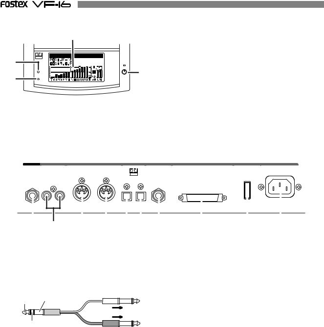
Display Section
59 |
57 |
OPTICAL |
|
|
60 |
|
58 |
ACCESS |
|
PHANTOM |
|
57. [ACCESS] LED
This LED lights ON when the internal hard disk drive or external SCSI device for backup purposes is writing or reading data.
58. [PHANTOM] LED
This lights ON when the phantom power is ON.
The phantom power is turned ON/OFF with the setup mode.
59. LCD (Liquid Crystal Display)
The recorder and mixer status and parameters are shown on the LCD.
60. Contrast Adjusting Knob
This is used to adjust the contrast (difference in brightness) of the LCD. Increase or decrease the contrast by turning it clockwise or counterclockwise, respectively.
Rear Panel
AUX SEND |
ST OUT |
MIDI |
DIGITAL / DATA |
FOOT SW |
SCSI |
POWER |
AC-IN |
|
|
IN |
|
OUT |
OPTICAL |
|
|
|
|
|
|
|
|
|
|
|
||
R |
L |
|
IN |
OUT |
|
|
|
|
61 |
62 |
63 |
64 |
65 66 |
67 |
68 |
69 |
70 |
61. [AUX SEND-1/2] Jack
*External effector or other devices are connected to output the AUX SEND 1/2 signals.
*Standard Output Level: -10dBV
*Use a Y-cable, as shown below, to connect an external effector since the ø6 TRS Phones jack is used.
TIP: |
GND |
To Effect 1 |
AUX1 |
|
|
|
|
|
RING: |
|
|
AUX2 |
To Effect 2 |
|
62. [ST OUT-L/R] Jack
*Master recorders and other devices are connected to output stereo L/R signals.
*Standard Output Level: -10dBV
*Connector: RCA (pin)
65. [DIGITAL/DATA IN] Jack
*Connect to OPTICAL DIGITAL OUT (S/P DIF) or adat DIGITAL OUT of an external digital device for signal input to the VF-16.
*This is used to load DAT/adat song data.
*Connector: Square optical
66. [DIGITAL/DATA OUT] Jack
*Connect to OPTICAL DIGITAL IN (S/P DIF) or adat DIGITAL IN of an external digital device for signal output from the VF-16.
*This is used to save DAT/adat song data.
*Connector: Square optical
67. [FOOT SW] Jack
*Punch IN/OUT option by connecting the Fostex Model 8051 foot switch (unlatched type).
63. [MIDI IN] Jack
*Connect to the MIDI OUT jack of an external MIDI device.
*MIDI control signals such as MMC (MIDI Machine Control) is mainly input.
*Connector: DIN 5 PIN
64. [MIDI OUT] Jack
*Connect to the MIDI IN jack of an external MIDI device.
*MIDI synchronization signals such as MTC (MIDI Time Code) and MIDI clock signals & song position pointers are mainly output.
*Connector: DIN 5 PIN
68. [SCSI] Connector
*This is where external SCSI devices (SCSI ID to 6) for backup purposes are connected.
*Connector: Half pitch D-sub, 50-pin, female
69. [POWER] switch
* This turns ON/OFF the power of the VF-16.
70. [AC IN] Jack
* This is where the accessory power cable is inserted.
For more details, refer to the respective instructions of each item.
20
About the hard disk storage device
The VF-16 is complete with a 3.5-inch E-IDE hard disk (storage device) which is formatted in the Master 16 mode. Therefore, there is no need to newly assemble a hard disk or to format the hard disk. The user can immediately start recording with the VF-16. Note that the current hard disk can also be replaced with another model for use with the VF-16. (However, please only use hard disks that Fostex recommends.)
Reformatting the hard disk
This section describes how to reformat the hard disk. The VF-16 adopts a “FDMS-3 (Fostex Disk Management System-3)” format which is a Fostex exclusive format. Eight additional tracks can be used in addition to recording and playing 16-tracks of uncompressed 44.1kHz/16 bit high quality sound.
<Precaution>
Note that, when you reformat your hard disk, you will erase all data saved or recorded on the hard disk, as well as all the settings made. Reformatting your hard disk restore the VF-16 back to the default setting.
Always make a point to check that there is no data that you need remaining on the hard disk prior to reformatting.
1.Turn ON the VF-16.
2.Press the [SETUP] key.
The system will go to the SETUP mode. The select display of the SETUP menu appears. (The highlight indicates the menu that is currently selected.)
The hard disk formatted in the “Standard” type upon newly formatting the hard disk will show “Standard” and “Erase”. The hard disk formatted in the “Quick” type upon newly formatting the hard disk will show “Standard” and “Quick”. The user can select one.
flashing
or
flashing |
3. Turn the [JOG] dial to highlight the “Disk Format” menu title.
“IDE” indicates the current drive. “SCSI” indicates the backup SCSI drive.
flashing
4. Press the [ENTER/YES] key while “IDE” is highlighted.
The menu to select the format type appears.
The display will appear as follows, according to the previous format type. “****” represents the name of the drive.
The hard disk is formatted with the access time of the unit sectors, while judging whether the
sectors are good or bad. The formatting time “Standard” tends to be longer with this type, however, the
reliability is better. Therefore, it is recommended that this default format type is selected under normal conditions.
This choice is only available when a hard disk previously formatted in the “Standard” type is being reformatted. With this format, the
“Erase” “Standard” type is maintained, while all data on the hard disk are erased.
The formatting time is shorter than the time required to format a “Standard” type.
This is a quick formatting procedure in which all hard disk sectors are considered to be good sectors. The formatting time is fast, however, the
“Quick” procedure cannot discover bad sectors.
Therefore, it is recommended that this format type is only used when formatting a new hard disk that Fostex has already confirmed to operate normally.
21
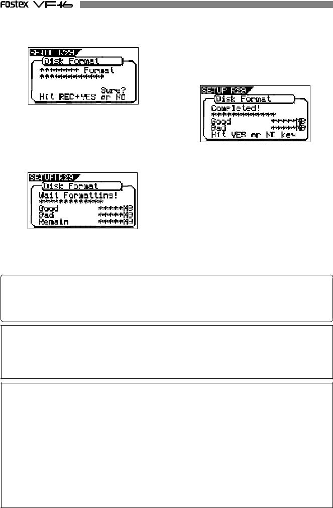
5. Select the format type with the [F FWD] key or [REWIND] key. Then press the [ENTER/YES] key.
The format type selected is set and “Sure?” flashes.
When the hard disk is successfully formatted (formatting completed), the number of sectors and noncontiguous sectors are shown after formatted, then “Completed!” lights up. Formatting is completed instantaneously if either “Erase” or “Quick” is selected and executed.
For this reason, the “Completed!” message lights up without showing the progress status while formatting is taking place.
6. Press the [ENTER/YES] key while the [RECORD] key is depressed.
If the “Standard” format is selected and executed, the formatting process takes place while showing the progress of the good sectors (Good ***MB) on the disk, bad sectors on the disk (Bad ***MB) and remainder (Remain ***MB). Nothing can be done during the formatting process. Please wait for a while until the process is completed.
7. Press the [EXIT/NO] key (or [STOP] key) to escape from the SETUP mode.
The Normal Display appears indicating the beginning of the program (P01) that is automatically created after formatting the hard disk.
Replacing a hard disk
<Operation Confirmed HD & Backup Media List for the VF-16>
The updated information on the operation-confirmed HD and backup media for VF-16 is mentioned in the following Fostex international web site.
<http: // www. fostex.co.jp/int/index.htm>
For those who are unable to check our web site, please contact the Fostex distributor in your territory.
<Warning>
This section describes the procedures to replace the hard disk. However, we recommended that the customer ask the Fostex Customer Service Department to replace the VF-16 hard disk. Note that the product is not warranted for any malfunctions that may occur after the customer replaces the hard disk on their own. Also note that Fostex will not be held liable for any accidents that may occur during the replacement process or any hard disk damages, if the customer decides to replace their own hard disk on their own.
<Precautions Upon Replacement>
*Always turn OFF the power of the VF-16 and unplug the power plug from the electric outlet when replacing the hard disk.
*Always place the hard disk on a flat and stable platform during the replacement process. Place a soft cloth under the unit to protect the product from scratching. Gloves are recommended to prevent any hand injuries.
<Precautions Upon Handling the Hard Disk>
*A hard disk is an extremely sensitive precision device. Never expose the hard disk to “strong shocks” when replacing, assembling or handling. Never leave the hard disk by a device that generates strong magnetic fields.
*Always set the DIP switch and Jumper of the newly assembled hard disk to the [MASTER] setting. The hard disk will not operate normally if the setting is set to [SLAVE] when the hard disk is assembled. Refer to the User’s Manual of the hard disk for more details on the DIP switch and Jumper settings.
*Note that the connector of some hard disks may be stiff, and thus make it difficult or impossible to insert or connect. Never apply excessive force to insert the connector in such case. Always make a point to gently insert the connector. Failure to do so may result in unexpected injuries or damage the hard disk.
22
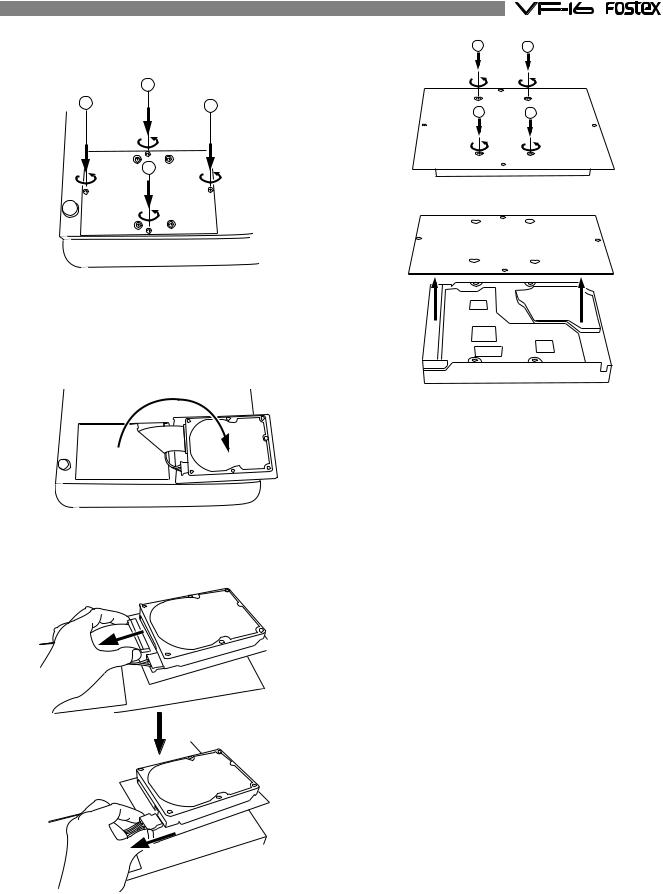
1. Unscrew the four screws from the bottom of the |
1 |
2 |
|
main unit that are fixing the panel. |
|
|
|
|
2 |
|
|
1 |
3 |
3 |
|
|
4 |
||
|
|
||
|
4 |
|
|
2. Turn over the panel that the hard disk is fixed according to the instructions shown in the figure below.
Note that hard disk cables will be connected.
Be careful not to apply excessive force when turning over the panel.
3. Remove the two cable connectors that are connected to the hard disk.
Gently hold the connector and slowly pull out.
4. After disconnecting the cables, remove the panel that is fixing the hard disk.
Unscrew the four screws with a screwdriver, as shown in the Figure.
5.Fix a new hard disk to the panel in the reverse order of removing the hard disk as performed earlier. Connect the cables. Then house the hard disk at
the bottom of the main unit.
Follow the <Precautions> described earlier, and properly assemble the parts.
When the new hard disk is successfully assembled, go to the next section. Now, format the unformatted hard disk.
23

Formatting the Hard disk
Carefully follow the instructions below to newly format the hard disk properly.
1. Turn ON the VF-16 after plugging the power cable in the electric outlet.
The VF-16 will startup. “Unformat!” will appear on the LCD. The menu will automatically go to the SETUP mode. The display showing the “Disk Format” menu appears.
6. Press the [EXIT/NO] key (or [STOP] key) to escape from the SETUP mode.
The Normal Display appears indicating the beginning of the program (P01) that is automatically created after formatting the hard disk.
<Normal Display>
2. Press the [ENTER/YES] key.
The drive selection display appears. “IDE” will be flashed.
flashing
3. Press the [ENTER/YES] key where the “IDE” is flashed.
The menu to select the format type appears. “****” represents the name of the drive.
flashing
<CAUTION>
Either the “Standard” or “Quick” format type can be selected. However, make sure that the “Standard” format type is selected when formatting a newly installed hard disk.
4. Press the [ENTER/YES] key where the “Standard” is flashed.
The format type selected is set and “Sure?” flashes.
5. Press the [ENTER/YES] key while the [RECORD] key is depressed.
The formatting process is started. The formatting process will take some time.
When the formatting is successfully completed, “Completed!” will light up on the display.
24
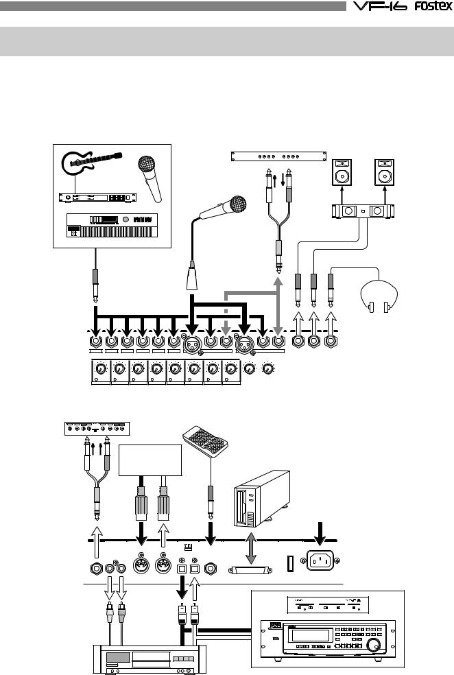
Chapter 2 Basic Recording and Playback
Connections of Peripheral Equipment
The VF-16 is equipped with input/output jacks to connect the following sound sources and external equipment. Always turn the [MASTER] fader, [MON OUT] knob and [PHONES] knob to “0” when connecting the external equipment to the input/output jacks.
Microphone |
Compressor/Limiter |
|
Monitor speaker |
|
|
||
|
|
|
|
|
Input |
Output |
|
Guitar & Processor |
|
|
|
|
Microphone |
|
|
|
|
Monitor amplifier |
|
Keyboard |
|
|
|
Unbalanced output |
|
|
|
Balanced output |
|
|
|
|
|
|
Headphone |
|
INPUT |
MON OUT |
PHONES |
1/9/A |
2/10/B |
3/11/C |
4/12/D |
5/13/E |
6/14/F |
|
7/15/G |
|
|
|
8/16/H |
L |
R |
||
|
|
|
|
|
|
|
|
BAL |
UNBAL |
INSERT |
BAL |
|
UNBAL |
INSERT |
|
|
|
|
|
|
|
TRIM |
|
|
|
|
MON OUT |
PHONES |
|
||
LINE |
MIC |
LINE |
MIC |
LINE |
MIC |
LINE MIC |
LINE MIC |
LINE MIC |
LINE MIC |
LINE |
MIC |
0 10 |
0 |
10 |
|
PEAK |
PEAK |
PEAK |
PEAK |
PEAK |
PEAK |
PEAK |
PEAK |
|
|
|
|
||||
1/9/A |
2/10/B |
3/11/C |
4/12/D |
5/13/E |
6/14/F |
7/15/G |
8/16/H |
|
|
|
|
||||
Signal processor etc. |
|
Foot switch |
|
|
|
|
|
|
|
|
|
|
|
|
Sequncer |
|
SCSI device |
|
||
|
PC w/sequence |
|
(Save/Load) |
|
|
|
|
software etc. |
|
|
|
|
|
|
MIDI OUT |
MIDI IN |
|
|
|
|
|
|
|
|
|
|
AC 100V |
AUX SEND |
ST OUT |
MIDI |
DIGITAL / DATA FOOT SW |
SCSI |
POWER |
AC-IN |
|
IN |
OUT |
OPTICAL |
|
|
|
|
|
|
|
|
||
R |
L |
|
IN OUT |
|
|
|
|
|
adat digital input |
|
Digital in/out |
|
Analog inputs |
(S/P DIF) |
adat digital output |
|
|
adat digital equipment
Master recorder etc.
25
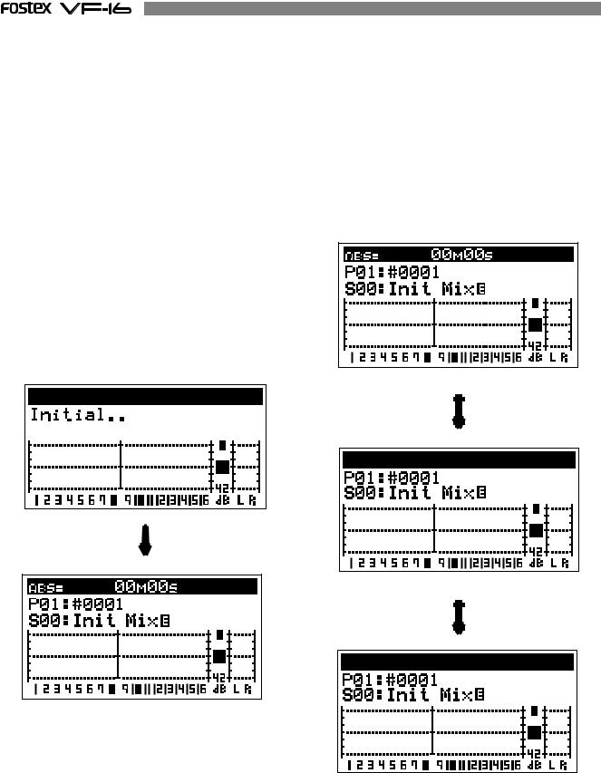
LCD
The follwing describes the contents shown on the LCD and their operations.
Menu shown when turning power ON
When the VF-16 is turned ON with a hard disk already formatted, the following menu will appear in order: [Initial... (Initializing)] & [Version] -> [Current Dr] -> [IDE] -> [Name of Hard disk (Instantly)] -> [Recording mode (Standard or Quick)].
The head of the program (ABS 0) will then start up at the time base when the power was turned OFF. The LCD menu appearing immediately after turning the power ON is called the “Normal Display”.
The “Normal Display” shows the following items for the 3 time bases:
*Current Location/Program Number & Program Title
*Scene Number & Scene Name
*Level Meter of Tracks 1-16
*Stereo OUT L/R Master Level/Meter
Switching the Time Base
The user can switch between time bases, by pressing the [DISP SEL] key, while the [SHIFT] key is depressed. In this case the time base alternates in the order of “1. ABS” -> “2. BAR/BEAT/CLK” -> “3. MTC” ->... The normal display always appears when the time base is switched. Make use of these displays accordingly.
Time Base: Normal Display in ABS.
Normal display
Time Base: Normal Display in BAR/BEAT/CLK.
Time Base: Normal Display in MTC.
26
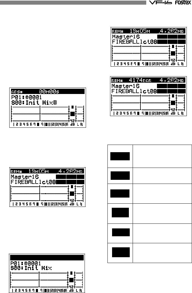
Switching with [DISP SEL] Key
Every time the [DISP SEL] key is pressed the LCD alternately shows the “1.
Normal Display of Current Time Base” -> “2. REMAIN Display of Current Time Base” -> “3. MTC Time Display Input”. The description of each display is defined below.
1. Normal Display of Current Time Base
*Current time according to current time base.
*Program number and program title.
The first 9 characters of the program title are shown.
*Scene number and scene name.
The first 9 characters of the scene name are shown.
*Level meter of tracks 1 to 16.
*L/R master level meter
2. REMAIN Display of Current Time Base
*REMAIN time and space available in mono-track converted units according to the current time base (the following is the case in ABS).*1
*Format type.
*Name of hard disk.
*Level meter of tracks 1 to 16.
*L/R master level meter.
3. MTC Time Display Input
*MTC time input.
“00H 00M 00S 00F” appears if there is no time input.
*Program number and program title.
The first 9 characters of the program title are shown.
*Scene number and scene name.
The first 9 characters of the scene name are shown.
*Level meter of tracks 1 to 16.
*L/R master level meter.
*1. The REMAINING time display appears as follows according to the time base that has been selected.
Time Base: ABS and MTC
Time Base: BAR/BEAT/CLK
*2. Icons of the program setup details appear at the right side of the menu. Refer to examples below.
This indicates recording/no recording setup by the “Rec Protect” menu. The icon shown here is indicating that it is presently set “Off” and thus recording is possible.
This is indicating the VF-16 sampling frequency (Fixed to 44.1kHz).
This indicates the drive setup by the “Drive Sel” menu. The icon here is indicating that it is set to an “E-IDE hard disk.”
This indicates the MIDI sync output signal setup by the “Midi Sync Out” menu. The icon here is indicating that it is presently set to “CLK.”
This indicates the slave type setup by the “Slave Type” menu.
This icon is indicating that it is presently set to “VARI.”
Frame rate figure setup by the “MTC Frame Rate” menu is indicated here. The icon here is indicating that it is presently set to “25 Frames.”
27
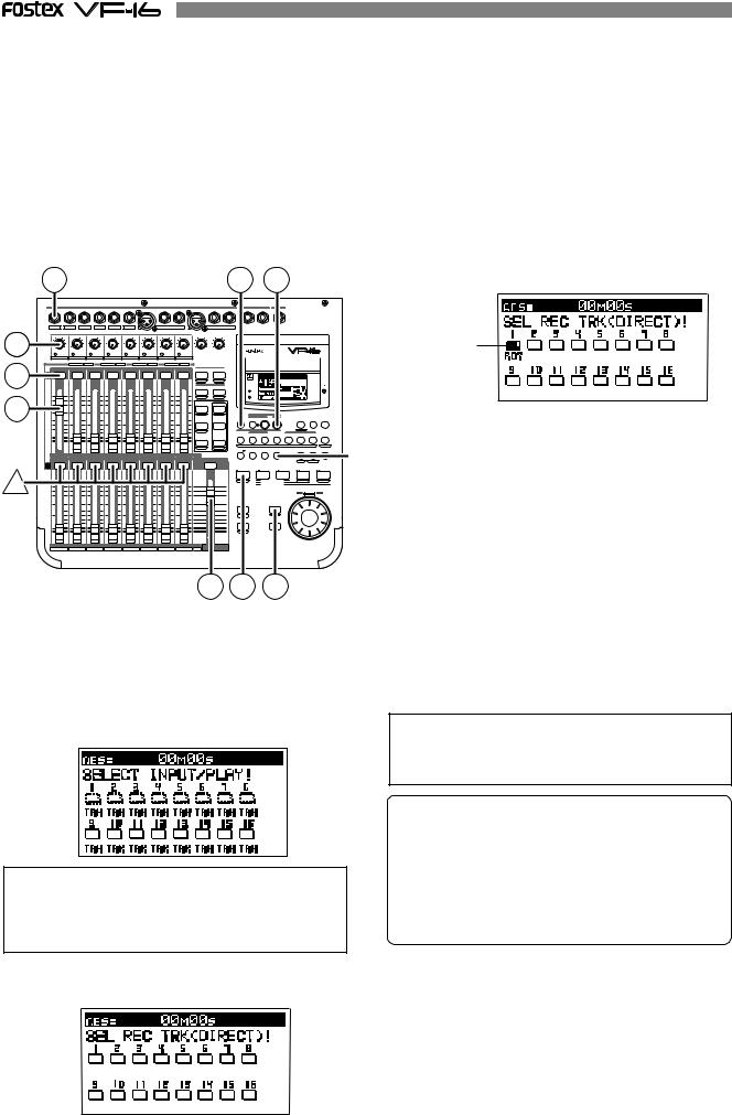
Instructions for DIRECT Record
This section describes the basic REC/PLAY procedures in the “DIRECT” recording mode, which is the easiest recording procedure and also provides recordings that most closely resemble the original. Hints and tips to successfully operate the VF-16 are included according to the workflow, ranging from the actual recording to mix down process. Both experienced and novice users of multitracker should try this process so as to learn the VF16 operations. The following description assumes that the VF-16 has been started up without any recordings.
Recording to One Track
Here, we will record to track 1 of the recorder. Check to see that the channel faders of ch1-16 and the master fader are set to -∞ (completely down) and that [TRIM] A to H are set to LINE position (fully turn to left). Also use (connect) a headphone or monitor speakers to monitor the sound.
1 |
2 |
3 |
4. Press the [CH STATUS/CH SEL] key of ch1 (Key: Flashing |
|
|
|
|
|
|
|
RED). |
INPUT |
MON OUT |
PHONES |
|
1/9/A |
2/10/B |
3/11/C |
4/12/D |
5/13/E |
6/14/F |
|
|
7/15/G |
|
|
|
8/16/H |
|
|
L |
R |
|
|
|
|
|
|
|
I n d i c a t e s |
|||
|
|
|
|
|
|
|
|
|
|
BAL |
|
UNBAL |
INSERT |
BAL |
|
UNBAL |
INSERT |
|
|
|
|
|
|
|
|
|
|
|
98 |
|
|
|
|
|
|
|
TRIM |
|
|
|
|
|
MON OUT |
PHONES |
|
|
|
|
|
|
|
|
|
|
|||
LINE |
MIC LINE |
MIC LINE MIC |
LINE |
MIC |
LINE MIC LINE MIC |
LINE MIC |
LINE |
MIC |
0 10 |
0 10 |
|
|
|
|
DIGITAL |
|
|
|
|
|
that ch1 is |
|||||||
|
|
|
|
|
|
|
|
|
|
|
||||||||||||||||||
PEAK |
PEAK |
|
PEAK |
PEAK |
PEAK |
|
PEAK |
PEAK |
PEAK |
|
|
|
|
|
MULTITRACKER |
|
|
|
|
|
||||||||
|
1/9/A |
2/10/B |
3/11/C |
4/12/D |
5/13/E |
6/14/F |
7/15/G |
8/16/H |
|
|
|
|
|
|
|
|
|
|
|
|
|
READY. |
||||||
4 |
CH STATUS |
ORANGE |
INPUT |
|
RED |
REC |
GREEN |
PLAY |
OFF |
MUTE |
RECALL |
STORE |
|
|
|
|
|
|
|
|
|
|
|
|||||
|
|
|
|
|
|
CH STATUS/CH SEL |
|
|
|
|
|
SCENE |
|
|
|
|
|
|
|
|
|
|
|
|
||||
|
|
|
|
|
|
|
|
|
|
|
|
|
|
DIRECT RCL |
MAP |
|
|
|
|
|
|
|
|
|
|
|
|
|
|
|
|
|
|
|
|
|
|
|
|
|
|
|
CLEAR |
|
|
|
|
|
|
|
|
|
|
|
|
||
|
|
|
|
|
|
|
|
|
|
|
|
|
|
EFF1 EFF EDIT EFF2 |
|
|
|
|
|
|
|
|
|
|
|
|
||
|
+6 |
|
+6 |
|
+6 |
|
+6 |
|
+6 |
+6 |
|
+6 |
+6 |
|
|
|
|
|
ACCESS |
|
|
|
|
|
|
|
|
|
7 |
|
|
|
|
|
|
|
|
|
|
|
|
|
|
MUTE |
MUTE |
|
|
|
|
|
|
|
|
|
|
|
|
|
|
|
|
|
|
|
|
|
|
|
|
|
|
CH PARAM EDIT |
|
|
PHANTOM |
|
|
|
|
|
|
|
|
|
||
0 |
|
0 |
|
0 |
|
0 |
|
0 |
0 |
|
0 |
0 |
|
|
EQ/COMP |
|
|
|
|
|
|
|
|
|
|
|
|
|
|
|
|
|
|
|
EFF1/EFF2 |
HI-G/F/Q |
|
|
|
|
|
|
|
|
|
|
|
5. Press the [EXIT/NO] key to return to the Normal Display. |
|||||||||
-10 |
|
-10 |
|
-10 |
|
-10 |
|
-10 |
-10 |
|
-10 |
-10 |
|
AUX1/AUX2 |
MID-G/F/Q |
CH STATUS SOURCE |
REC TRK |
REC TRK |
|
DISP SEL PGM SEL |
SETUP |
|
||||||
|
|
|
|
|
|
|
|
|
|
|
|
|
|
|
PRE/POST |
COMP |
|
|
|
REC ASSIGN |
|
|
|
|
|
|
|
|
|
|
|
|
|
|
|
|
|
|
|
|
|
|
|
|
|
|
|
BUSS |
DIRECT |
|
|
|
|
|
|
|
|
|
-20 |
|
-20 |
|
-20 |
|
-20 |
|
-20 |
-20 |
|
-20 |
-20 |
|
PAN |
LO-G |
|
|
|
|
|
|
|
|
|
|
|
[CH STATUS/CH SEL] key of ch1 -> Alternately Flashes |
|
|
|
|
|
|
|
|
|
|
|
|
|
|
|
|
|
AUTO RTN |
|
|
|
TIME BASE |
|
|
|
||||
|
-30 |
|
-30 |
|
-30 |
|
-30 |
|
-30 |
-30 |
|
-30 |
-30 |
|
PRE/POST |
|
|
|
|
|
|
|
|
|
|
|
||
|
|
|
|
|
|
|
|
|
|
|
AUTO PUNCH |
|
|
|
CLIPBOARD |
|
A RTN |
|
|
|||||||||
|
-40 |
|
-40 |
|
-40 |
|
-40 |
|
-40 |
-40 |
|
-40 |
-40 |
|
|
|
|
START |
IN |
OUT |
END |
IN |
|
ALIGN SEL |
OUT |
A PLAY |
|
|
|
-∞ |
|
-∞ |
|
-∞ |
3 |
-∞ |
|
-∞ |
-∞ |
6 |
-∞ |
-∞ |
|
TRACK |
|
|
1 |
2 |
3 |
MARK |
4 |
5 |
6 |
7 |
SCENE SEQ |
! |
GREEN/RED |
|
1 |
|
2 |
|
|
4 |
|
5 |
|
7 |
8 |
|
|
|
|
|
|
|
|
|
|
|
||||||
|
|
|
|
|
|
|
|
|
|
|
|
|
|
|
FADER |
CH VIEW |
|
|
|
|
UNDO/ |
|
|
VARI |
|
|
|
|
|
|
|
|
|
|
|
|
|
|
|
|
|
|
|
|
|
|
HOLD/ |
STORE |
EDIT |
REDO |
|
|
PITCH |
LOCATE |
SCRUB |
|
|
|
|
|
|
|
|
|
CH STATUS/CH SEL |
|
|
|
|
|
|
|
|
RECORD |
STOP |
|
PLAY |
|
REWIND |
F FWD |
* Indicates that trk1 is “READY”. |
|||||
|
|
|
|
|
|
|
|
|
|
|
|
|
|
|
|
|
|
|
|
|
|
|
|
P.EDIT |
LOC MEM |
|
|
|
! |
|
|
|
|
|
|
|
|
|
AUTO PUNCH |
CLIPBOARD PLAY |
PREV NEXT |
|
|
|
|
|
|
|
|
|
|
|
|
LOCATE ABS 0 |
|
|
||
+6 |
+6 |
+6 |
+6 |
+6 |
+6 |
+6 |
+6 |
+6 |
|
LOCATE REC END |
|
|
||
|
|
|
|
|
|
|
|
|
ADJUST |
EXIT/NO |
JOG |
6. Press [RECORD] key to set trk1 to the Input Monitor mode |
||
0 |
0 |
0 |
0 |
0 |
0 |
0 |
0 |
0 |
SHUTTLE |
|||||
|
|
|
||||||||||||
|
|
|
|
|
|
|
|
|
|
FADER |
|
|
|
|
|
-10 |
-10 |
-10 |
-10 |
-10 |
-10 |
-10 |
-10 |
-10 |
|
|
|
(Key: Flashing RED). |
|
|
-30 |
-30 |
-30 |
-30 |
-30 |
-30 |
-30 |
-30 |
-30 |
LEVEL |
ENTER/YES |
|
||
|
|
|
|
|
|
|
|
|
|
EJECT |
|
|
||
|
-20 |
-20 |
-20 |
-20 |
-20 |
-20 |
-20 |
-20 |
-20 |
ADJUST |
|
|
|
|
|
-40 |
-40 |
-40 |
-40 |
-40 |
-40 |
-40 |
-40 |
-40 |
|
|
|
|
|
|
-∞ |
-∞ |
-∞ |
-∞ |
-∞ |
-∞ |
-∞ |
-∞ |
-∞ |
SHIFT |
|
|
|
9 |
10 |
11 |
12 |
13 |
14 |
15 |
16 |
TRACK MASTER |
|
|
7. |
Set the ch1 fader and master fader to “0”. |
A |
B |
C |
D |
E |
F |
G |
H |
INPUT |
|
|
||
|
|
|
|
|
|
|
|
7 |
6 |
5 |
8. |
Output sound from the sound source while adjusting the |
|
|
|
|
|
|
|
|
|
|
|
||
|
|
|
|
|
|
|
|
|
|
|
|
[TRIM]1/9/A gain to an optimal level. |
Preparing to Record (refer to Figure above)
1.Connect the sound source to record to the [INPUT] 1/9/ A jack.
2.Press the [INPUT SEL] key (Key: Flashes ORANGE).
[CH STATUS/CH SEL] key of ch9-16 -> Flashes GREEN Indicates that all channels are [TRACK] (the following LCD display appears).
WARNING!
In DIRECT Recording, all channel faders are basically [TRACK]. If there is channel in which the [INPUT] (RED: Flashing), press the [CH STATUS/CH SEL] key of that channel so it is a [TRACK].
3.Press the [DIRECT-REC TRK] key (RED: Flashing).
The menu to select the track to record appears.
The guideline for optimal gain is the border of the [PEAK] LED lighting ON or OFF, when the sound source is at the maximum volume. Adjustments should also ensure that the signal does not exceed 0 on the LCD level meter.
To listen to the sound turn up the [MON OUT] knob or [PHONES] knob.
WARNING!
Be careful not to excessively raise the volume of the [MON OUT] or [PHONES] level. Prolonged exposure to loud sounds may have an adverse effect on hearing.
Tips: Changing the recording mode
To change the DIRECT recording mode to the BUSS recording mode, press the [BUSS-REC TRK] key while the tracks to be directly recorded are selected using the step above. "Rec Mode Change!" appears and "Sure?" flashes on the screen. Pressing the [ENTER/YES] key cancels the selection of tracks for the DIRECT recording and changes the display to the track selection screen for the BUSS recording.
RECORD
1.Press the [REWIND] key while the [STOP] key is depressed, to locate ABS 0 (Locate ABS 0).
2.Press the [PLAY] key while the [RECORD] key is depressed to start recording.
The RED light of [CH STATUS/CH SEL] key and [RECORD] key of ch1 lights up to indicate that ch1 is recording.
28
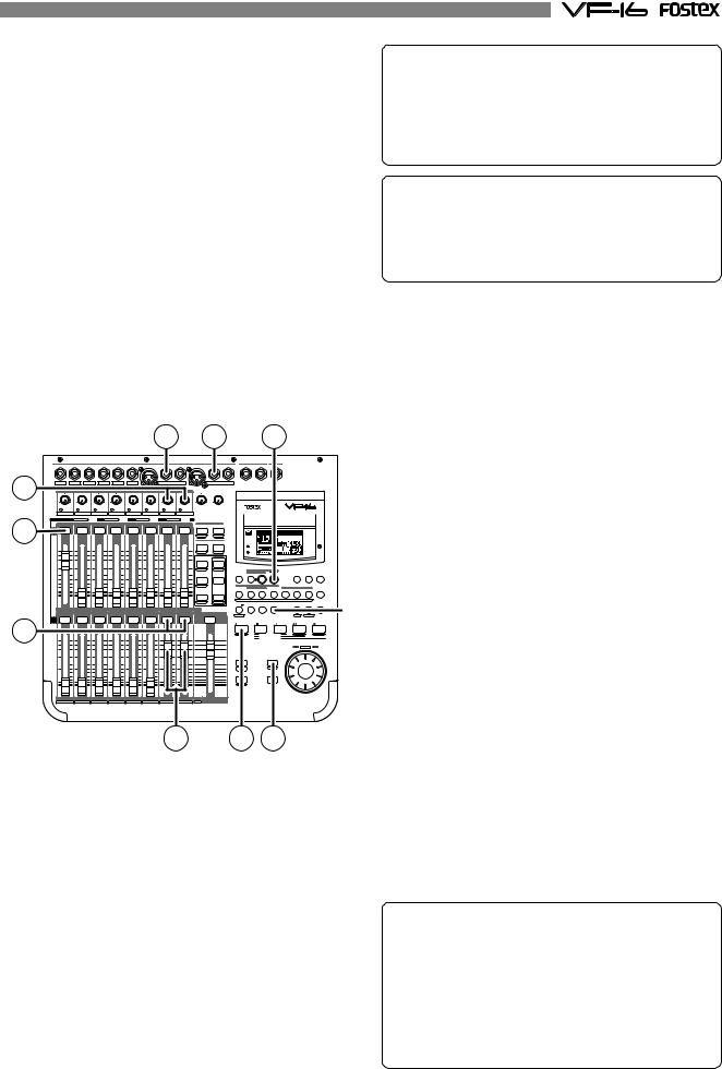
3.Press the [STOP] key to stop the recording operations.
The LCD will show a “Please Wait” message and then return to the Normal Display.
This completes the process to record on track 1.
Check the sound recorded using the following procedures.
PLAY
1.Press the [REWIND] key while the [STOP] key is depressed to locate ABS 0.
2.Press the [PLAY] key to start playback.
The play level of track 1 can be adjusted with the ch1 fader. This concludes the procedures to check the sound recorded.
Cancel READY Status of Recording Track
Press once again the [DIRECT-REC TRACK] key that is lit up RED, then press the [CH STATUS/CH SEL] key of the channel that is in the READY mode to cancel the ready state of the track recorded and to put that track in the SAFE mode. Then press the [EXIT/NO] key to return to the Normal Display.
Tips: UNDO/REDO
Press the [UNDO/REDO] key after recording to return to the prerecording state (UNDO). Press the [UNDO/REDO] key again to return to the original state of the recording on track 1 (REDO). The UNDO/REDO function is effective for all recordings.
RECORDING to 2 Tracks
With track 1 now recorded, we will record the stereo sound source to tracks 15 and 16 of the recorder.
1 |
1 |
7 |
|
|
|
|
|
|
|
|
INPUT |
|
|
|
|
|
|
|
|
1/9/A |
2/10/B |
3/11/C |
4/12/D |
5/13/E |
6/14/F |
|
|
7/15/G |
|
|
|
|
8/16/H |
|
|||
|
|
|
|
|
|
|
|
|
BAL |
|
UNBAL |
INSERT |
BAL |
|
|
UNBAL |
INSERT |
|
|
|
|
|
|
|
TRIM |
|
|
|
|
|
MON OUT |
PHONES |
|||
|
LINE |
MIC |
LINE |
MIC |
LINE |
MIC |
LINE MIC |
LINE MIC |
LINE |
MIC |
LINE MIC |
LINE |
MIC |
0 |
10 |
0 |
10 |
|
PEAK |
PEAK |
PEAK |
PEAK |
PEAK |
PEAK |
PEAK |
PEAK |
|
|
|
|
|||||
1/9/A |
2/10/B |
3/11/C |
4/12/D |
5/13/E |
6/14/F |
7/15/G |
8/16/H |
CH STATUS |
ORANGE |
INPUT |
RED |
REC |
GREEN |
PLAY |
OFF |
MUTE |
|
! 3 |
|
|
CH STATUS/CH SEL |
|
|
|
SCENE |
|
|
|
|
|
|
|
|
|
RECALL |
STORE |
|
|
|
|
|
|
|
|
DIRECT RCL |
MAP |
|
|
|
|
|
|
|
|
CLEAR |
|
|
|
|
|
|
|
|
|
EFF1 EFF EDIT EFF2 |
||
+6 |
+6 |
+6 |
+6 |
+6 |
+6 |
+6 |
+6 |
|
|
|
|
|
|
|
|
|
|
MUTE |
MUTE |
|
|
|
|
|
|
|
|
CH PARAM EDIT |
|
0 |
0 |
0 |
0 |
0 |
0 |
0 |
0 |
|
EQ/COMP |
EFF1/EFF2 |
HI-G/F/Q |
||||||||
|
|
|
|
|
|
|
|
PRE/POST |
COMP |
-10 |
-10 |
-10 |
-10 |
-10 |
-10 |
-10 |
-10 |
|
|
|
|
|
|
|
|
|
|
AUX1/AUX2 |
MID-G/F/Q |
-20 |
-20 |
-20 |
-20 |
-20 |
-20 |
-20 |
-20 |
|
|
-30 |
-30 |
-30 |
-30 |
-30 |
-30 |
-30 |
-30 |
PRE/POST |
|
-40 |
-40 |
-40 |
-40 |
-40 |
-40 |
-40 |
-40 |
|
|
-∞ |
-∞ |
-∞ |
-∞ |
-∞ |
-∞ |
-∞ |
-∞ |
PAN |
LO-G |
FADER |
CH VIEW |
||||||||
|
1 |
2 |
3 |
4 |
5 |
6 |
7 |
8 |
TRACK |
|
|
|
|
CH STATUS/CH SEL |
|
|
|
|
|
! 3 |
+6 |
+6 |
+6 |
+6 |
+6 |
+6 |
+6 |
+6 |
+6 |
|
0 |
0 |
0 |
0 |
0 |
0 |
0 |
0 |
0 |
|
-10 |
-10 |
-10 |
-10 |
-10 |
-10 |
-10 |
-10 |
-10 |
|
-20 |
-20 |
-20 |
-20 |
-20 |
-20 |
-20 |
-20 |
-20 |
|
-30 |
-30 |
-30 |
-30 |
-30 |
-30 |
-30 |
-30 |
-30 |
|
-40 |
-40 |
-40 |
-40 |
-40 |
-40 |
-40 |
-40 |
-40 |
|
-∞ |
-∞ |
-∞ |
-∞ |
-∞ |
-∞ |
-∞ |
-∞ |
-∞ |
|
9 |
10 |
11 |
12 |
13 |
14 |
15 |
16 |
TRACK MASTER |
|
A |
B |
C |
D |
E |
F |
G |
H |
INPUT |
|
|
|
|
|
|
|
|
6 |
|
|
|
2 |
|
|
|
MON OUT |
PHONES |
|
|
|
|
L |
|
R |
|
|
|
|
|
DIGITAL |
|
|
|
|
|
MULTITRACKER |
|
|
|
ACCESS |
|
|
|
|
|
PHANTOM |
|
|
|
|
|
|
REC ASSIGN |
|
|
|
|
BUSS |
DIRECT |
|
TIME BASE |
|
|
CH STATUS SOURCE |
REC TRK REC TRK |
DISP SEL |
SEL |
SETUP |
|
|
AUTO RTN |
|
|
|
|
|
|
|
|
AUTO PUNCH |
|
|
|
CLIPBOARD |
|
A RTN |
|
START |
IN |
OUT |
END |
IN |
|
ALIGN SEL |
OUT |
A PLAY |
1 |
2 |
3 |
|
4 |
5 |
6 |
7 |
|
|
|
|
MARK |
|
|
|
|
|
|
|
|
UNDO/ |
|
|
VARI |
|
|
HOLD/ |
STORE |
EDIT |
REDO |
|
|
PITCH |
LOCATE |
SCRUB |
PGM SEL |
|
|
|
|
|
P.EDIT |
LOC MEM |
|
RECORD |
|
STOP |
|
PLAY |
|
REWIND |
F FWD |
|
AUTO PUNCH |
|
CLIPBOARD PLAY |
|
PREV |
|
NEXT |
||
|
|
LOCATE |
ABS |
0 |
|
|
|
|
|
|
LOCATE REC END |
|
|
|
|
||
|
|
|
|
|
|
JOG |
|
|
|
|
|
|
|
|
SHUTTLE |
|
|
FADER |
|
|
|
|
|
|
|
|
ADJUST |
|
EXIT/NO |
|
|
|
|
|
|
LEVEL |
|
EJECT |
|
|
|
|
|
|
ADJUST |
|
|
|
|
|
|
|
|
|
|
ENTER/YES |
|
|
|
|
||
SHIFT |
|
|
|
|
|
|
|
|
5 |
4 |
6.Set the ch15 and ch16 fader and master fader to “0”.
7.Output sound from the sound source while adjusting the [TRIM] 7/15/G and 8/16/H gain to an optimal level.
RECORD
1. |
Locate the time to start recording. |
2. |
Press the [PLAY] key while the [RECORD] key is |
! |
depressed to start recording. |
The [CH STATUS/CH SEL] key and [RECORD] key of ch15 |
|
|
and 16 lights up RED to indicate that the channels are |
|
recording. By increasing the fader level of track 1, the |
|
user can record to tracks 15 and 16 (overdubbing) while |
|
listening to the playback sounds of track 1. |
3. Press the [STOP] key to stop recording. |
|
PLAY
Preparing to Record
1.Connect the stereo sound source to record to [INPUT] jacks 7/15/G and 8/16/H.
2.Press the [DIRECT-REC TRK] key (RED: Flashing).
3.Press the [CH STATUS/CH SEL] key for ch15 and ch16 (RED: Flashing).
Trk15 and 16 will go to the “READY” mode. The other tracks will be in the “SAFE” mode (Key: Light OFF).
4.Press the [EXIT/NO] key.
[CH STATUS/CH SEL] key of ch 15 and 16 -> GREEN/RED: Alternately Flash
*Indicates that trk15 and 16 are “READY”.
5.Press the [RECORD] key to put trk15 and 16 in the Input Monitor mode (RED: Flashing).
Trk15 and 16 will got to the Input Monitor mode.
1.Locate the time to playback.
2.Press the [PLAY] key to start playback.
Ch1, ch15 and ch16 faders can be used to adjust the play level of each track.
After recording, put the “READY” track in the “SAFE” mode, as described earlier.
Tips: UNDO/REDO
Press the [UNDO/REDO] key after recording to return to the prerecording state (UNDO). Press the [UNDO/REDO] key again to return to the original state of the recording on two tracks (REDO).
Tips: MUTE
Press the [CH STATUS/CH SEL] key in the Normal Display to MUTE (silence) that channel ([CH STATUS/CH SEL] key: Light OFF).
29
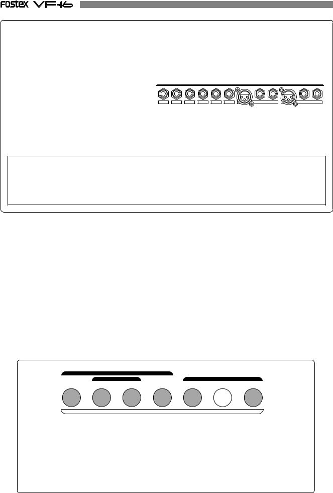
DIRECT Recording
After reading the instructions up to this point, you are probably aware that the track recorded varies according to the input channel. With DIRECT Recording, the relationship between the channel input and track recorded are as follows.
Connect to [INPUT] 1/9/A: Recordable on track 1/9. Connect to [INPUT] 2/10/B: Recordable on track 2/10. Connect to [INPUT] 3/11/C: Recordable on track 3/11. Connect to [INPUT] 4/12/D: Recordable on track 4/12. Connect to [INPUT] 5/13/E: Recordable on track 5/13. Connect to [INPUT] 6/14/F: Recordable on track 6/14. Connect to [INPUT] 7/15/G: Recordable on track 7/15. Connect to [INPUT] 8/16/H: Recordable on track 8/16.
[1/9/A], etc. also appears on the panel.
INPUT
1/9/A |
2/10/B |
3/11/C |
4/12/D |
5/13/E |
6/14/F |
7/15/G |
|
8/16/H |
|
|
|
|
|
|
BAL |
UNBAL |
INSERT BAL |
UNBAL |
INSERT |
Based on the above, it is possible to simultaneously record 8 input channels with DIRECT Recording. Try recording to other tracks according to the procedures already explained.
WARNING!
*It is also possible to simultaneously record 16 tracks. However, there will be 2 consecutive tracks on which the same sound is recorded.
*The channel with the ORANGE light ON ([INPUT]) from among ch9-16 of the [CH STATUS/CH SEL] keys cannot output the audio sound on the tracks corresponding to 9-16, therefore, recording will be prohibited.
As a result, the READY state cannot be established with the [DIRECT-REC TRK] key.
Locating a mark point using a Memory Key
You can store desired locate memory points using the Memory keys shown in the figure below.
Each of the 6 keys shown in gray below can hold two memory points: one is primarily used as an edit point for track editing functions such as Auto return, Auto punch and Copy/paste, while the other is a locate memory point.
The edit point also can be used as a locate memory point when the corresponding editing function is not active.
The key shown in white below ([CLIPBOARD-ALIGN SEL/MARK 6]) can also hold two points but you can store only one point for a locate memory (MARK 6). The other point the key holds is the ALIGN SEL point, which is copied automatically from the point stored in the [CLIPBOARD IN] key when carrying out copy clip (or move clip) during the Copy/paste (or Move/paste).
Therefore, up to 13 locate memory points are available when no editing function is active. You can store memory points with any time base setting.
|
AUTO RTN |
|
|
|
|
|
|
AUTO PUNCH |
|
CLIPBOARD |
|
||
START |
IN |
OUT |
END |
IN |
ALIGN SEL |
OUT |
1 |
2 |
3 |
4 |
5 |
6 |
7 |
|
|
|
MARK |
|
|
|
The following details are saved in each Memory Key.
[AUTO RTN-START/MARK 1] Key |
-> |
START point and MARK 1 memory. |
[AUTO PUNCH-IN/MARK 2] Key |
-> |
PUNCH IN point and MARK 2 memory. |
[AUTO PUNCH-OUT/MARK 3] Key |
-> |
PUNCH OUT point and MARK 3 memory. |
[AUTO RTN-END/MARK 4] Key |
-> |
END point and MARK 4 memory. |
[CLIPBOARD-IN/MARK 5] Key |
-> |
CLIP IN point and MARK 5 memory. |
[CLIPBOARD-ALIGN SEL/MARK 6] Key -> |
ALIGN SEL point and MARK 6 memory. |
|
[CLIPBOARD-OUT/MARK 7] Key |
-> |
CLIP OUT point and MARK 7 memory. |
30
 Loading...