

Forney D85 User Manual
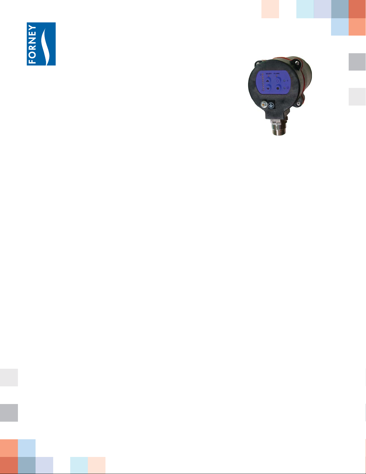
D85 Unitized Flame Detector
Forney’s D85 series ame detectors
provide unparalleled ease of installation
and operation, with fully automatic
ame characterization and optimum
gain detection.
Features & Bene ts
• Rapid installation and con guration
with quick disconnects and fully
automated tuning.
• Advanced, programmable settings for
more demanding applications
• Expanded diagnostic analysis for
superior ame characterization and
troubleshooting.
• Multiple UV and IR ame detection
options support a wide range of
combustion processes including:
industrial burners, duct burners,
re nery applications, low NOx
burners, waste fuel units and
incinerators.
Product Overview
e Forney D85 series is a microprocessor based ame detector
utilizing a solid state ame detection sensor. e D85 incorporates an
internal ame relay with automatically set ON/OFF thresholds and
advanced programming features for ne tuning.
Forney’s D85 detects the modulation of the target ame’s amplitude
( ame “ icker”) over a wide frequency. During the detector setup the
amplitudes of the target ame are automatically stored in the ame
detector along with optimum ON/OFF criteria. e appropriate
sensor gain is also automatically selected and stored. Forney D85
detectors incorporate full self-diagnostic and electronic self-checking.
Forney D85 ame detectors are powered by 24Vdc with standard
analog 4-20mA ame signal strength output. Electrical connection
• Integrated sensor and electronics
eliminates need for external ampli ers.
• Standard NEMA 4X, IP66 housing
for Class I, Div 2 environments
• Optional CEX models for ATEX Ex
II 2 G/D environments
Forney Corporation • 3405 Wiley Post Road • Carrollton, TX 75006 • 800-356-7740 • Fax 972-458-6650 • www.forneycorp.com
is via an 8-pin electrical quick-disconnect (QD) tting for standard
models. CEX models utilize internal terminal blocks.
Forney D85 ame detectors are available in multiple models based on
spectral range (UV or IR), hazardous area classi cations and agency
approvals.
D85 Series Unitized Flame Detector
Part Number for D85 Detector Heads
Pub # 404005-26
Rev 11/2012
D85
Base Model
__ __
Sensor
UV
IR
__ __
Mount
FM = Front Mount
FO = Fiber Optic
__ __ __
Electrical Connection
QD = Quick Disconnect
CEX = CEX compliant
__ __
Optional Filter
K3 = K3 Filter
(for UV only)
Sample Part Number: D85 UV FM QD = D85 Model with UV sensor, Front Mount and Quick Disconnect Connection.
Mechanical Specifi cations:
Housing Material: Standard Models: Engineered material - GE Valox CEX Models: Aluminum, painted fi nish
Standard Models: NEMA 4X, IP66 / Class I Div II CEX Models: Ex II 2 G/D, ATEX certifi ed
Detector Weight: Standard Models: 3.30 lbs (1.5kg) CEX Models: 9.5 lbs (4.3kg)
Cooling / Purge Air
Requirements:
Source: Clean, dry, cool
Volume: 10 SCFM (113 l/min) at 3/8” threaded mounting fl ange, or 1 inch “Y” fi tting, mounted on scanner sight pipe. Temperature near
the upper limit of the operating range and/or dirty fuels may require up to 15 SCFM (425 l/min).
Pressure: Adequate to overcome furnace or windbox pressure
Environmental: -40° F to + 150°F (-40°C to +65°C), 0-95% relative humidity, non-condensing
Mounting
(Ordered Separately):
Standard Models: P/N 35-318-1, Standard, non-metallic, 1” NPT female pipe mount fl ange with 3/8” NPT female cooling air connection
P/N 35-318-2, Standard, non-metallic, 1” BSP female pipe mount fl ange with 3/8” BSP female cooling air connection
P/N 129-182-1, Optional, aluminum 1” NPT kit for standard models with 3/8” NPT female cooling air connection
P/N 129-182-2, Optional, aluminum 1” BSP kit for standard models with 3/8” BSP female cooling air connection
CEX Models: P/N 129-168-1, 1” NPT female pipe mount fl ange with 3/8” NPT female cooling air connection
P/N 129-168-2, 1” BSP female pipe mount fl ange with 3/8” BSP female cooling air connection
Optical:
UV Models: 295 to 340 nanometers (K3 option 310-500 nanometers); IR Models: 830 to 1100 nanometers
Electrical Specifi cations:
Input Power: 24 Vdc, +20%, -15% supply current 200mA
Electrical Connection: Standard Models: 8-pin quick disconnect
CEX Models: internal terminal blocks
Relay Output: FLAME RELAY, SPST (N.O.)
FAULT RELAY, SPST (N.C.)
Contact Rating: Minimum: 10mA @ 5 Vdc
Maximum: 2A@30 Vdc, 2A@230 Vac Resistive load
Analog Output: Optically isolated 4-20mA dc current referenced to 24
Vdc common, maximum connected load: 750 Ohms.
Forney recommends the 60-2685-X 24 Vdc power
supply for best performance and for a SELV rating of
the 4-20mA analog output leads.
Status Indication: Multiple LED indication for fl ame signal strength,
fl ame relay, ready, target, background select and fault
codes
Cable Specifi cation: Quick Connect P/N 401119-xx, Bulk Cable
P/N 401119-00 Multi-core, 8 (color coded) Eight
#18 AWG with foil wrap and overall braided shield.
PLTC-ER rating.
Temperature Rating: -40°F to 221°F (-40°C to 105°C)
Cable Jacket: PVC (fl ame-retardant, low smoke, zero
halogen)
Nominal O.D. 0.44” (11.2 mm); Maximum O.D.
0.48” (12.2 mm)
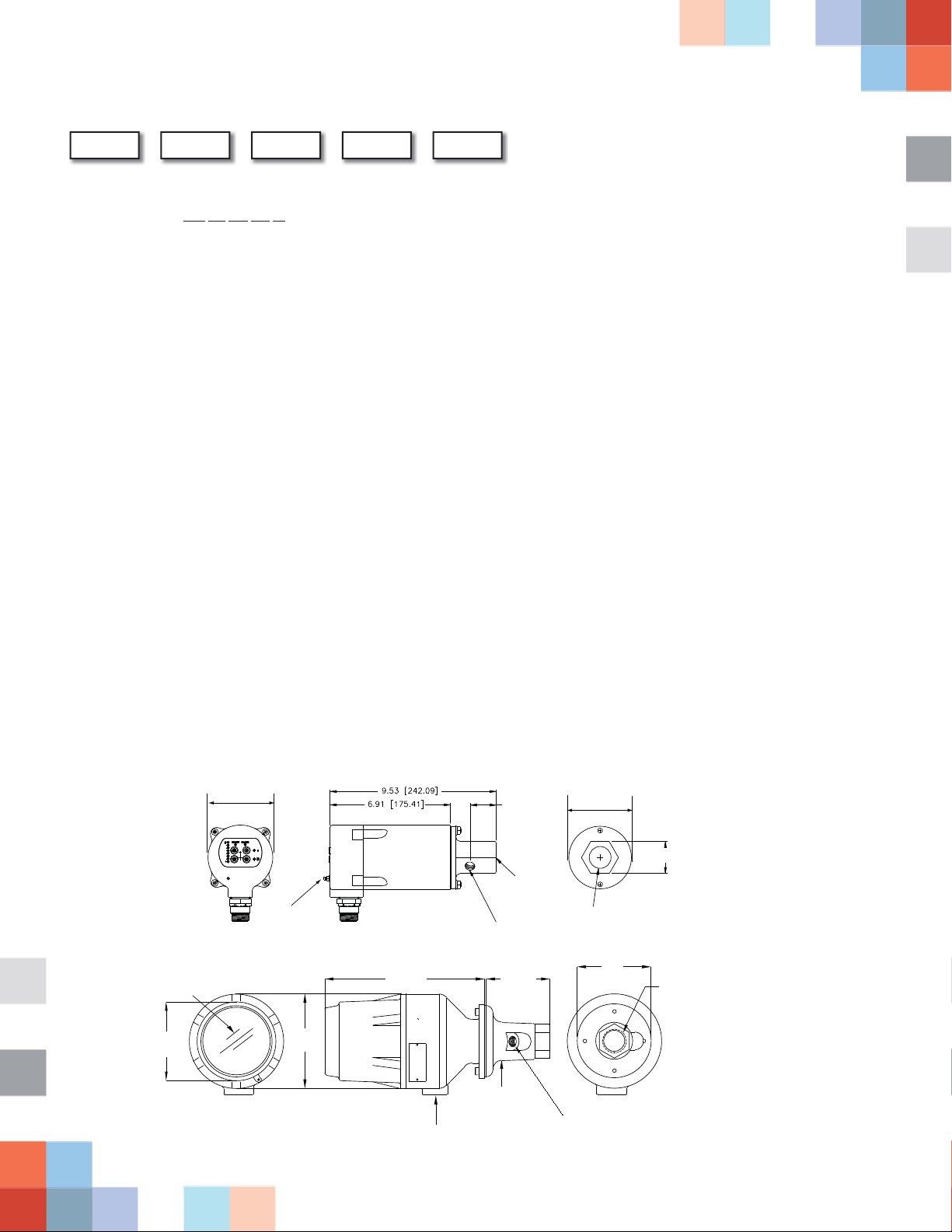
Standard Models
CEX Models
4.41
[112]
DIMENSIONS IN INCHES (mm)
VIEWING
WINDOW
3.72 [94.49]
GROUNDING
SCREW
5.28
[134]
PURGE AIR
CONNECTION
8.94 (227) 3.56 (90)
MOUNTING FLANGE
1” BSP
3/4” NPT THREADED OPENING
FOR CABEL ENTRY
1.46 [36.97]
MOUNTING
FLANGE
(ORDERED
SEPARATELY)
3/8” THREADED OPENING
SIGHT PIPE
CONNECTION
FOR COOLING AIR
3.59 [91.28]
4.13
[105]
1.84 [46.79]
THREADED
1” BSP
Forney Corporation • 3405 Wiley Post Road • Carrollton, TX 75006 • 800-356-7740 • Fax 972-458-6650 • www.forneycorp.com
 Loading...