

Page 1
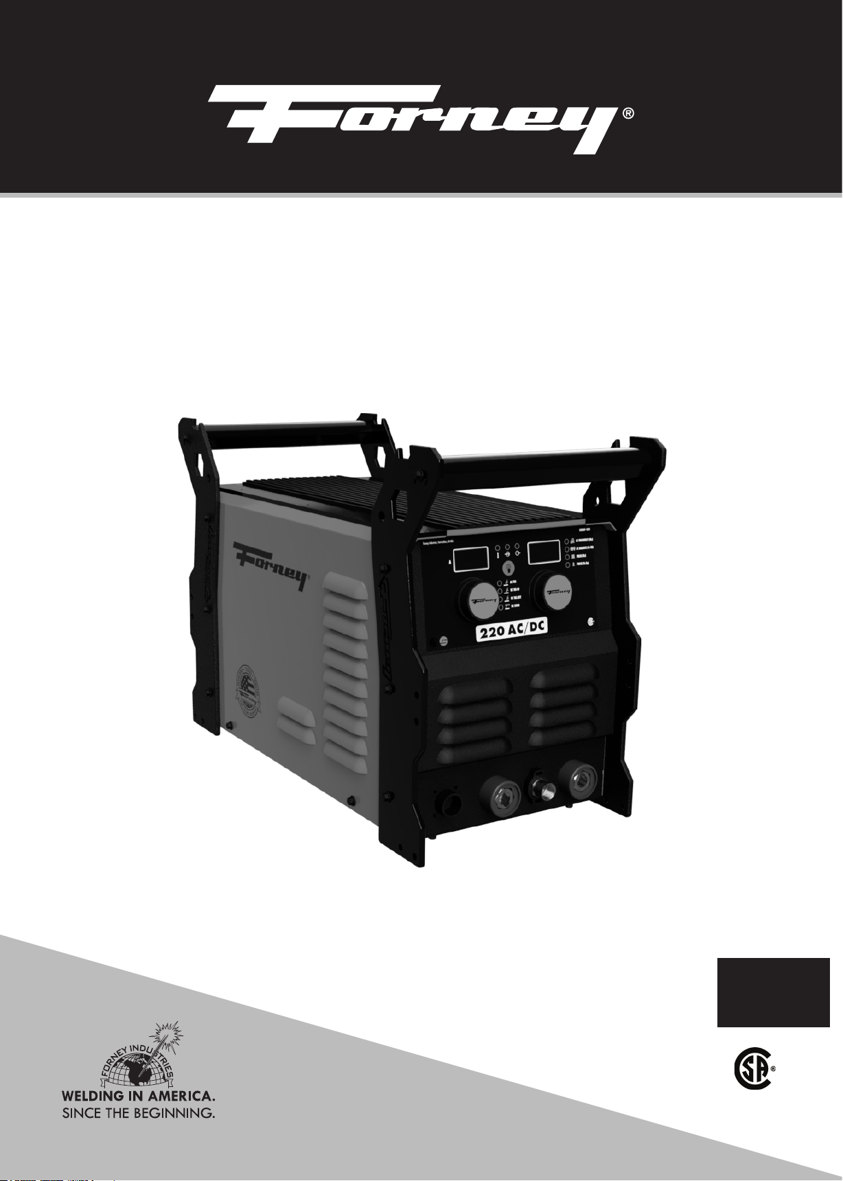
220 AC/DC STICK/TIG ARC
WELDER OPERATING MANUAL
ENGLISH
ITEM# 420
REV 08.08.2019
Page 2
FIVE WAYS TO ORDER
Forney Promise
Web: www.forneyind.com
Phone: 800-521-6038
Fax: 970-498-9505
Mail: Forney Industries
2057 Vermont Drive
Fort Collins, CO 80525
Email: [email protected]
U.S. Facilities:
- Fort Collins, CO
- Tipp City, OH
We are committed to your success regardless of location, size or
needs. We understand it is your goal to get the job done right,
and we are ready to help you do just that.
President's Message
We market the highest quality tools, equipment and accessories
for the do-it-yourselfer and professional. Our passion and
dedication in bringing new products to the industrial and retail
market, combined with our personal service, is unmatched in our
industry. Our ability to listen to our customers’ needs enables us to
create solutions to their problems.
Our dedication to the highest quality customer service within our
corporate headquarters and the service provided in the field is
unequaled. We are committed to creating the best solutions to our
customer’s needs. Above all, our employees will provide the same
respect and caring attitude within the organization as they are
expected to share with every Forney customer. Our goal will be to
exceed our customers’ expectations through empowered people,
guided by shared values and commitments.
Copyright© 2019 Forney Industries,
Inc. All rights reserved. Unauthorized
reproduction and/or distribution is
subject to US copyright laws.
2
We work hard so our customers trust us because of our integrity,
teamwork and innovation in the welding & metalworking industry.
80 years of unmatched product quality and an unwavering
commitment to our customers.
When our customers succeed we succeed.
Steven G. Anderson
STEVEN G. ANDERSON, President & CEO
WWW.FORNEYIND.COM
Page 3
TECHNICAL ISSUES?
FORNEY CAN HELP!
Thank you for choosing Forney! Please note: The store you purchased
this m achine from DOES NOT handle product r eturns. F orney
Industries will repair or replace defective products at no charge to you!
When you call Forney's Technical Service department, you will speak
to a
to get your machine up and running in as little time as possible. In fact,
trained product and application expert. Forney's primary goal is
the majority of issues can be fixed over the phone! Please be near your
machine when you call, so the Forney technician can guide you.
Speaking to a Forney Technician directly helps us gather better data,
and i mprove our p roducts. I t is our h ighest priority t o ensure our
customers are cared for.
WE MAKE IT EASY!
Please contact Forney Industries Technical
Service at 800-521-6038 x2 or
[email protected] for inquires,
technical and general questions.
WWW.FORNEYIND.COM
3
Page 4

Table of Contents
WARRANTY ..........................................................................................................................................................................3
TABLE OF CONTENTS ............................................................................................................................................................4
SYMBOLS LEGEND ................................................................................................................................................................5
SAFETY SUMMARY ...............................................................................................................................................................5
PRINCIPAL SAFETY STANDARDS .....................................................................................................................................5
CALIFORNIA PROPOSITION 65 WARNING .....................................................................................................................6
EMF INFORMATION .......................................................................................................................................................6
PERSONAL PROTECTION ...............................................................................................................................................6
FIRE PREVENTION ..........................................................................................................................................................7
HIGH FREQUENCY RADIATION ......................................................................................................................................8
ARC WELDING ..............................................................................................................................................................8
ELECTRIC SHOCK ...........................................................................................................................................................8
NOISE ...........................................................................................................................................................................9
ADDITIONAL SAFETY INFORMATION .............................................................................................................................9
INSTALLATION ....................................................................................................................................................................10
WELDER SPECIFICATIONS ............................................................................................................................................10
SITE SELECTION ...........................................................................................................................................................10
POWER SOURCE CONNECTION..................................................................................................................................10
GENERATORS ..............................................................................................................................................................11
EXTENSION CORDS .....................................................................................................................................................11
VENTILATION ..............................................................................................................................................................11
ADDITIONAL WARNINGS ............................................................................................................................................11
GETTING TO KNOW YOUR WELDER ....................................................................................................................................13
DESCRIPTION ..............................................................................................................................................................12
WELDER LAYOUT AND CONTROLS ..............................................................................................................................12
OPERATION ........................................................................................................................................................................16
PERFORMANCE DATA PLATE & DUTY CYCLE .................................................................................................................14
INTERNAL THERMAL PROTECTION ...............................................................................................................................14
WELDING PREPARATION..............................................................................................................................................15
SETUP FOR STICK WELDING (SMAW) ...........................................................................................................................15
SETUP FOR TIG WELDING (GTAW) WITH LIFT ARC ........................................................................................................16
GAS SELECTION ..........................................................................................................................................................16
MAINTENANCE & SERVICING .............................................................................................................................................19
GENERAL MAINTENANCE ...........................................................................................................................................19
TROUBLESHOOTING ...........................................................................................................................................................21
MACHINE PARTS DIAGRAM & CONSUMABLES LIST ..............................................................................................................23
TIG TORCH & TIG CONSUMABLES LIST (SOLD SEPARATELY) ..................................................................................................20
USER NOTES ......................................................................................................................................................................24
4
WWW.FORNEYIND.COM
Page 5
CAUTION!
BEFORE INSTALLING, OPERATING OR CARRYING OUT MAINTENANCE ON THE MACHINE, READ THE CONTENTS
OF THIS MANUAL CAREFULLY, PAYING PARTICULAR ATTENTION TO THE SAFETY RULES AND HAZARDS.
In the event of these instructions not being clear, please contact your
Forney Authorized Dealer or Forney Customer Service 1-800-521-6038.
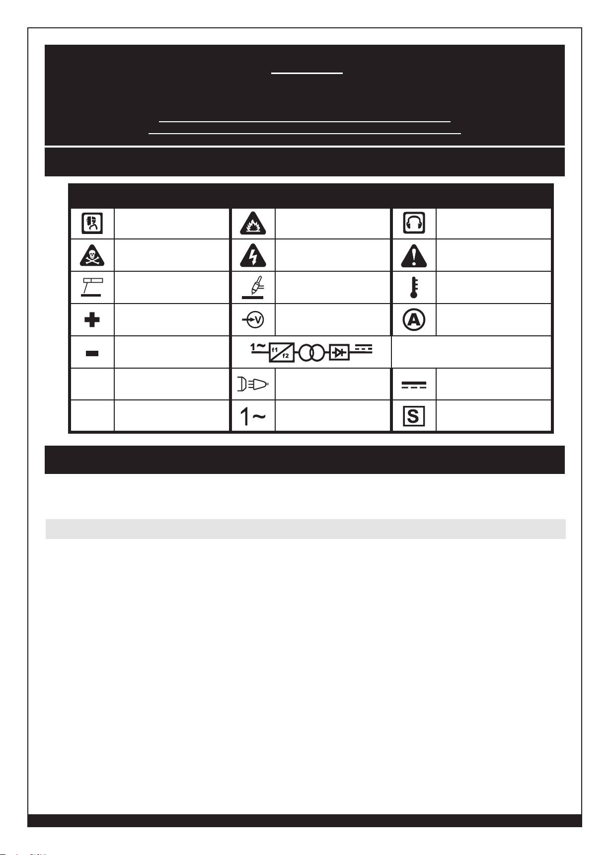
Symbols Legend
SYMBOL
I
O
ARC RAYS HAZARD
POISON
STICK (SMAW) TIG (GTAW) TEMPERATURE
POSITIVE DINSE INPUT VOLTAGE AMPERAGE
NEGATIVE DINSE
ON LINE CONNECTION DIRECT CURRENT (DC)
OFF
MEANING
HAZARD
Safety Summary
SYMBOL MEANING SYMBOL MEANING
FIRE HAZARD NOISE HAZARD
ELECTRICAL HAZARD WARNING/CAUTION
SINGLE PHASE STATIC FREQUENCY
CONVERTER TRANSFORMER RECTIFIER
SINGLE PHASE ALTERNATING
CURRENT (AC)
SUITABLE FOR WELDING IN AN
ENVIRONMENT WITH INCREASED
RISK OF ELECTRIC SHOCK
The data within this safety summary are highlights of various safety standards. It is
recommended that you familiarize yourself with the standards listed below before beginning
welding.
Principal Safety Standards
• ANSI Z49.1: SAFETY IN WELDING AND CUTTING - Obtainable from the American Welding Society, 550 NW Le Jeune
Road, Miami, FL 33126 Telephone (800) 443-9353, Fax (305) 443-7559 - www.aws.org.
• OSHA 29 CFR, Part 1910, Subpart Q.: WELDING, CUTTING AND BRAZING - Obtainable from your state OSHA office
or U.S. Dept. of Labor OSHA, Office of Public Affairs, Room N3647, 200 Constitution Ave., Washington, DC 20210 www.osha.gov.
• AWS F4.1: SAFE PRACTICES FOR THE PREPARATION FOR WELDING AND CUTTING OF CONTAINERS AND PIPING
FOR WELDING AND CUTTING. - Obtainable from the American Welding Society, 550 NW Le Jeune Road, Miami, FL
33126 Telephone (800) 443-9353, Fax (305) 443-7559 - www.aws.org.
• AWS A6.0. WELDING AND CUTTING CONTAINERS WHICH HAVE HELD COMBUSTIBLES - Obtainable from the
American Welding Society, 550 NW Le Jeune Road, Miami, FL 33126 Telephone (800) 443-9353, Fax (305) 443-7559
- www.aws.org.
• NFPA 70: NATIONAL ELECTRICAL CODE - Obtainable from the National Fire Protection Association, 1 Batterymarch
Park, P.O. Box 9101, Quincy, MA 02269-9101 Telephone (617) 770-3000 Fax (617) 770-0700 - www.nfpa.org.
• CGA Publication P-1: SAFE HANDLING OF COMPRESSED GASES IN CONTAINERS - Obtainable from Compressed
Gas Association, 14501 George Carter Way, Suite 103, Chantilly, VA 20151 Telephone (703) 788-2700 Fax (703)
961-1831 - www.cganet.com.
• CSA W117.2 - Code for SAFETY IN WELDING AND CUTTING. - Obtainable from Canadian Standards Association,
178 Rexdale Blvd., Etobicoke, Ontario M9W 1R3 - www.csa.ca.
WWW.FORNEYIND.COM
5
Page 6
• ANSI Z87.1 - SAFE PRACTICE FOR OCCUPATION AND EDUCATIONAL EYE AND FACE PROTECTION - Obtainable
from the American National Standards Institute, 11 West 42nd St., New York, NY 10036 Telephone (212) 642-900, Fax
(212) 398-0023 - www.ansi.org.
• NFPA 51B: STANDARD FOR FIRE PREVENTION DURING WELDING, CUTTING, AND OTHER HOT WORK- Obtainable
from the National Fire Protection Association, 1 Batterymarch Park, P.O. Box 9101, Quincy, MA 02269-9101 Telephone
(617) 770-3000 Fax (617) 770-0700 - www.nfpa.org.
California Proposition 65 Warning
WARNING: This product can expose you to chemicals, including lead, which are known to the State of California to
cause cancer and birth defects or other reproductive harm. For more information go to www.P65Warnings.ca.gov. P65
details at forneyind.com. Wash hands after use.
EMF Information
Welding current, as it flows through the welding cables, will cause electromagnetic fields. There has been and still is some
concern about such fields. However, after examination, the committee of the National Research Council concluded that:
“The body of evidence, in the committee’s judgment, has not demonstrated that exposure to power-frequency electric and
a magnetic field is a human health hazard.” However, studies are still going forth and evidence continues to be examined.
Until the final conclusions of the research are reached, you may wish to minimize your exposure to electromagnetic fields
when welding.
To reduce magnetic fields in the workplace, use the following procedures:
1. Keep electrode and ground cables close together by twisting or taping them when possible.
2. Arrange cables to one side and away from the operator.
3. Do not coil or drape cables around your body.
4. Keep welding power source and cables as far away from operator as practical.
5. Connect ground clamp to workpiece as close to the cut or weld as possible.
ABOUT PACEMAKERS & HEARING AIDS:
Pacemaker and hearing aid wearers consult your doctor first. If cleared by your doctor, then following the above
procedures is recommended.
Personal Protection
Weld
ing processes of any kind can be dangerous not only to the operator but to any person situated near the
equipment, if safety and operating rules are not strictly observed.
THE WELDING ARC PRODUCES VERY BRIGHT ULTRAVIOLET AND INFRARED LIGHT. THESE
ARC RAYS WILL DAMAGE YOUR EYES AND BURN YOUR SKIN IF YOU ARE NOT
PROPERLY PROTECTED. To reduce the risk of injury from arc rays, read, understand, and follow the safety
instructions. In addition, make certain that anyone else that uses this welding equipment, or is a bystander in the
welding area understands and follows these safety instructions as well. Helmets and filter should conform to ANSI Z87.1
stan dards.
• Do not look at an electric arc without proper protection. A welding arc is extremely bright and intense and, with
inadequate or no eye protection, the retina can be burned, leaving a permanent dark spot in the field of vision. A
shield or helmet with a #10 shade filter lens (minimum) must be used.
• Provide bystanders with shields or helmets fitted with an appropriate shade filter lens.
• Do not strike a welding arc until all bystanders and you (the welder) have welding shields and/or helmets in place.
• Do not wear a cracked or broken helmet and replace any cracked or broken filter lenses immediately.
• Do not allow the uninsulated portion of the TIG torch to touch the ground clamp or grounded workpiece to prevent an
arc flash from being created on contact.
• Wear protective clothing. The intense light of the welding arc can burn the skin in much the same way as the sun, even
through lightweight clothing. Wear dark clothing of heavy material. The shirt worn should be long sleeved and the
collar kept buttoned to protect chest and neck.
• Protect against reflected arc rays. Arc rays can be reflected off shiny surfaces such as a glossy painted surface,
aluminum, stainless steel, and glass. It is possible for your eyes to be injured by reflected arc rays even when wearing
a protective helmet or shield. If welding with a reflective surface behind you, arc rays can bounce off the surface and
off the filter lens. It can get inside your helmet or shield and into your eyes. If a reflective background exists in your
6
WWW.FORNEYIND.COM
Page 7
welding area, either remove it or cover it with something non-flammable and non- reflective. Reflective arc rays can
also cause skin burn in addition to eye injury.
• Flying sparks can injure. Wear proper safety equipment to protect eyes and face. Shape tungsten electrode on grinder
wearing proper protection and in a safe location. Keep flammables away and prevent fire from flying sparks.
FUMES, GASSES, AND VAPORS CAN CAUSE DISCOMFORT, ILLNESS, AND DEATH!
To reduce the risk, read, understand, and follow the safety instructions. In addition, make certain that anyone else that uses
this welding equipment or is a bystander in the welding area, understands and follows these safety instructions as well.
• Read and understand manufacturers Safety Data Sheets (SDS) and Material Safety Data Sheets (MSDS).
• Do not weld in an area until it is checked for adequate ventilation as described in ANSI standard Z49.1. If ventilation
is not adequate to exchange all fumes and gasses generated during the welding process with fresh air, do not weld
unless you (the welder) and all bystanders are wearing air-supplied respirators.
• Do not heat metals coated with, or that contain, materials that produce toxic fumes (such as galvanized steel), unless
the coating is removed. Make certain the area is well ventilated, and the operator and all bystanders are wearing airsupplied respirators.
• Do not weld, cut or heat lead, zinc, cadmium, mercury, beryllium, antimony, cobalt, manganese, selenium, arsenic,
copper, silver, barium, chromium, vanadium, nickel, or similar metals without seeking professional advice and
inspection of the ventilation of the welding area. These metals produce extremely toxic fumes which can cause
discomfort, illness and death.
• Do not weld or cut in areas that are near chlorinated solvents. Vapors from chlorinated hydrocarbons, such as
trichloroethylene and perchloroethylene, can be decomposed by the heat of an electric arc or its ultraviolet radiation.
These actions can cause phosgene, a highly toxic gas to form, along with other lung and eye- irritating gasses. Do
not weld or cut where these solvent vapors can be drawn into the work area or where the ultraviolet radiation can
penetrate to areas containing even very small amounts of these vapors.
• Do not weld in a confined area unless it is being ventilated or the operator (and anyone else in the area) is wearing
an air-supplied respirator.
• Stop welding if you develop momentary eye, nose, or throat irritation as this indicates inadequate ventilation.
Stop work and take necessary steps to improve ventilation in the welding area. Do not resume welding if physical
discomfort persists.
Fire Prevention
FIRE OR EXPLOSION CAN CAUSE DEATH, INJURY, AND PROPERTY DAMAGE! To reduce these
risks, read, understand and follow the safety instructions. In addition, make certain that anyone else that uses this welding
equipment, or is a bystander in the welding area, understands and follows these safety instructions as well. Remember:
arc welding by nature produces sparks, hot spatter, molten metal drops, hot slag and hot metal parts that can start fires,
burn skin and damage eyes.
• Do not wear gloves or other clothing that contains oil, grease, or other flammable substances.
• Do not wear flammable hair preparations.
• Do not touch the hot weld bead or weld puddle until fully cooled.
• Do not weld in an area until it is checked and cleared of combustible and/or flammable materials. Be aware that
sparks and slag can fly 35 feet and can pass through small cracks and openings. If work and combustibles cannot be
separated by a minimum of 35 feet, protect against ignition with suitable, snug-fitting, fire resistant, covers or shields.
• Do not weld on walls until checking for and removing combustibles touching the other side of the walls.
• Connect the ground cable to the workpiece as close as possible to the welding area. Do not connect ground cables
to building framing or other locations away from the welding area. This increases the possibility of welding current
passing through alternate circuits, creating fire hazards and other safety hazards.
• Do not weld, cut, or perform other such work on used barrels, drums, tanks, or other containers that had a flammable
or toxic substance. The techniques for removing flammable substance and vapors, to make a used container safe for
welding or cutting, are quite complex and require special education and training.
• Do not strike an arc on a compressed gas or air cylinder, and never allow any electrically “hot” parts to touch a
cylinder. Doing so will create a brittle area that can result in a violent rupture immediately or at a later time as a result
of rough handling.
• Ensure any compressed gas cylinders in the work area have properly operating regulators rated for the gas and
pressure used. All hoses, fittings, etc. should be in good condition.
• Do not stand in front of or put your head or face in front of a cylinder valve outlet when opening the valve.
• If a cylinder is not in use or connected for use, keep a valve protection cap in place to protect the valve.
WWW.FORNEYIND.COM
7
Page 8

• Keep cylinders upright and securely chain them to a fixed support to prevent tipping.
• Keep cylinders away from areas where they may be subjected to physical damage or accidentally struck. Keep them
a safe distance from any source of flame, sparks, or heat.
• Do not weld or cut in an area where the air may contain flammable dust (such as grain dust), gas, or liquid vapors
(such as gasoline).
• Do not handle hot metal, such as the workpiece or electrode stubs, with bare hands.
• Wear leather gloves, heavy long sleeve shirt, cuff-less pants, high-topped shoes, helmet, and cap. As necessary, use
additional fire-resistant protective clothing to cover and protect the upper and lower body. Hot sparks or metal can
lodge in rolled up sleeves, pant cuffs, or pockets. Sleeves and collars should be kept buttoned and pockets eliminated
from the shirt front.
• Have fire extinguisher equipment handy for immediate use. A portable chemical fire extinguisher, type ABC, is
recommended.
• Wear ear plugs when welding overhead to prevent spatter or slag from falling into ear.
• Make sure welding area has a good, solid, safe floor, preferably concrete or masonry, not tiled, carpeted, or made of
any other flammable material.
• Protect flammable walls, ceilings, and floors with heat resistant covers or shields.
• Check welding area to make sure it is free of sparks, glowing metal or slag, and flames before leaving the welding
area.
• Wear garments free of oil or other flammable substances such as leather gloves, thick cotton shirts with no synthetic
materials, cuffless trousers, closed toed shoes. Keep long hair pulled back.
• Remove any combustibles such as lighters and matches before doing any welding.
• Follow requirements in OSHA and NFPA for hot work and have an extinguisher nearby.
High Frequency Radiation
• High Frequency (H.F) can interfere with radio navigation, safety services, computers and communication equipment.
• It is the user’s responsibility to have a qualified electrician promptly correct any interference problem resulting from the
installation. Electrician should regularly check and maintain installation.
• Stop using the equipment if notified by the FCC about interference.
• Keep H.F. source doors and panels tightly shut and keep spark gaps at correct setting.
Arc Welding
• Computers and computer driven equipment can be harmed with electromagnetic energy.
• Be sure all equipment is compatible with electromagnetic energy.
• Keep welding cables short to reduce interference.
• Follow manual to install and ground machine.
• If interference continues, shield the work area or move the welding machine.
Electric Shock
WARNING: ELECTRIC SHOCK CAN KILL! To reduce the risk of death or serious injury from shock, read,
understand, and follow the safety instructions. In addition, make certain that anyone else who uses this welding
equipment, or who is a bystander in the welding area understands and follows these safety instructions as well.
IMPORTANT! TO REDUCE THE RISK OF DEATH, INJURY, OR PROPERTY DAMAGE, DO NOT
ATTEMPT OPERA TION of this welding equipment until you have read and understand the following safety summary.
• Do not, in any manner, come into physi cal contact with any part of the welding current circuit. The welding current
circuit includes:
a. the workpiece or any conductive material in contact with it,
b. the ground clamp,
c. the electrode or welding wire,
d. any metal parts on the electrode holder, or TIG torch.
• Do not weld in a damp area or come in contact with a moist or wet surface.
• Do not attempt to weld if any part of clothing or body is wet.
8
WWW.FORNEYIND.COM
Page 9
• Do not allow the welding equipment to come in contact with water or moisture.
• Do not drag welding cables, TIG torch, electrode holder or welder INPUT POWER CABLE (8) through or allow them
to come into contact with water or moisture.
• Do not touch welder, attempt to turn welder ON or OFF if any part of the body or clothing is moist or if you are in
physical contact with water or moisture.
• Do not attempt to plug the welder into the power source if any part of body or clothing is moist, or if you are in
physical contact with water or moisture.
• Do not connect ground clamp to electrical conduit, and do not weld on electrical conduit.
• Do not alter INPUT POWER CABLE or plug in any way.
• Do not attempt to plug the welder into the power source if the ground prong on INPUT POWER CABLE plug is bent
over, broken off, or missing.
• Do not allow the welder to be connected to the power source or attempt to weld if the welder, welding cables, welding
site, or welder INPUT POWER CABLE are exposed to any form of atmospheric precipitation, or salt water spray.
• Do not carry coiled welding cables around shoulders, or any other part of the body, when they are plugged into the
welder.
• Do not modify any wiring, ground connections, switches, or fuses in this welding equipment.
• Wear welding gloves to help insulate hands from welding circuit.
• Keep all liquid containers far enough away from the welder and work area so that if spilled, the liquid cannot
possibly come in contact with any part of the welder or electrical welding circuit.
• Replace any cracked or damaged parts that are insulated or act as insulators such as welding cables, INPUT POWER
CABLE, or electrode holder immediately.
• When not welding, cut wire back to contact tip or remove electrode from electrode holder.
Noise
Noise can cause permanent hearing loss. Welding processes can cause noise levels that exceed safe limits. You must
protect your ears from loud noise to prevent permanent loss of hearing.
• To protect your hearing from loud noise, wear protective ear plugs and/or ear muffs.
• Noise levels should be measured to be sure the decibels (sound) do not exceed safe levels.
Additional Safety Information
For additional information concerning welding safety, refer to the standards listed at the beginning of this safety summary
and comply with them as applicable.
WWW.FORNEYIND.COM
9
Page 10
Installation
Welder Specifications
Primary (Input) Volts 120VAC/230VAC
Maximum Output 220A
Phase Single
Frequency 50/60Hz
Recommended Circuit Breaker 50A for 230V or 30A for 120V
Extension Cord Recommendations 230V- 3 conductor # 8AWG
Generator Requirements 230V -Minimum 10,000W continuous output with no low-idle
CSA Rated Output and Duty Cycle Refer to the data plate of your machine and the DUTY CYCLE
Dimensions 22" (558.8mm) X 11" (279.4mm) X 15.5" (393.7mm)
Recommended Electrode Diameter Up to 3/16” (depending on type)
Site Selection
120V -3 conductor #12AWG or larger up to 25 ft.
function (or low-idle off), 5% THD Max.
120V- Minimum 5,000W continuous output with no low-idle
function (or low-idle off), 5% THD Max.
section of this manual, page 14.
BE SURE TO LOCATE THE WELDER ACCORDING TO THE FOLLOWING GUIDELINES:
• In areas free from moisture and dust;
• In areas with ambient temperature between 30° to 90°F;
• In areas free from oil, steam and corrosive gases;
• In areas not subjected to abnormal vibration or shock;
• In areas not exposed to direct sunlight or rain;
• Place at a distance of 12” or more from walls or similar obstructions that could restrict natural air flow for cooling.
Power Source Connection
Before you make any electrical connection, make sure that the POWER SWITCH is OFF, power supply voltage and
frequency available at site are those stated in the ratings label of your welder.
The main power supply voltage should be within ±10% of the rated main power supply voltage. Too low a power supply
voltage may cause poor welding performance. Too high a power supply voltage will cause components to overheat and
possibly fail. The welder outlet must be:
• Correctly installed, if necessary, by a qualified electrician;
• Correctly grounded (electrically) in accordance with national and local regulations;
• Connected to an electric circuit that is rated for sufficient amperage per the ratings label of your welder.
If you are unsure of any of the above, have your outlet inspected by a qualified electrician before using the welder.
NOTE:
• Periodically inspect INPUT POWER CABLE for any cracks or exposed wires. If it is not in good condition, have it
repaired by a Service Center.
• Do not cut off the grounding prong or alter the plug in any way and do not use any adapters between the welder’s
INPUT POWER CABLE and the power source receptacle.
• Do not violently pull the INPUT POWER CABLE to disconnect it from power outlet.
• Do not lay material or tools on the INPUT POWER CABLE. The INPUT POWER CABLE may be damaged and result in
electrical shock.
• Keep the INPUT POWER CABLE away from heat sources, oils, solvents or sharp edges.
• Do not use this welder on a circuit with a Ground Fault Circuit Interrupter (GFCI) on it. GFCIs are tripped by welding
arcs and your welding operations will be interrupted regularly.
10
WWW.FORNEYIND.COM
Page 11
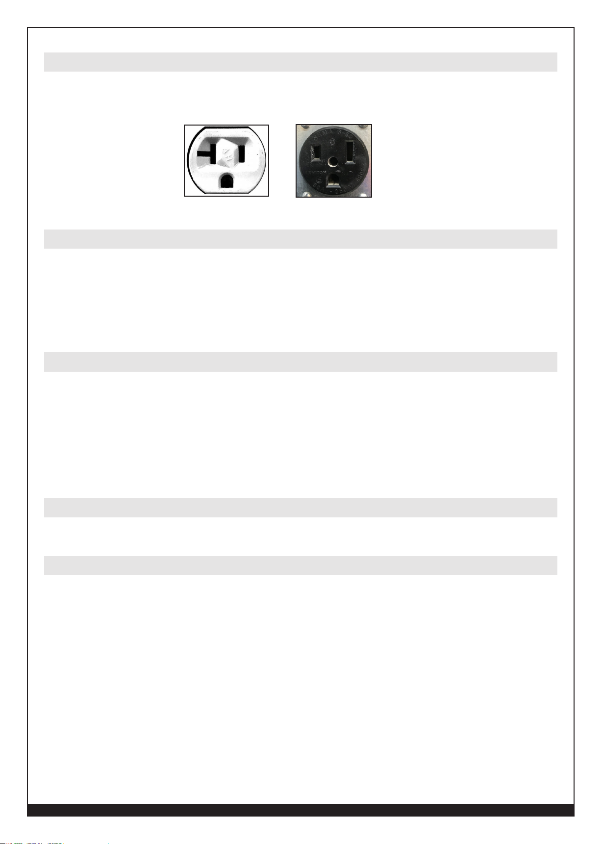
Using the 230 volt – 120 volt Plug Adapter
If a 230V (50A) circuit is not available, you can connect your 220 AC/DC Forney welder to 120V outlet (with a 30A
breaker) using the plug adapter. When using the plug adapter, use lower power settings on the machine to avoid frequent
circuit breaker trips. At maximum settings on 120V, the machine will draw more than 20 amps regularly.
230V/50A120V/20A
Generators
This welder can be operated from an AC generator. As this is a dual voltage machine please ensure that when using on
230V, the generator must supply a minimum of 10,000 watts of continuous output. When using the 120V option, the
generator must supply a minimum of 5,000 watts of continuous output. The generator must not have an auto-idle fuel
saving feature or must have the option to turn auto-idle off. The generator must run at full speed at all times while your
welder is plugged into it or you risk damaging your welder. Any other power draws on the generator or anything that
reduces the generator RPM may damage your welder.
Extension Cords
For optimum welder performance, an extension cord should not be used unless absolutely necessary. If necessary, care
must be taken in selecting an extension cord appropriate for use with your specific welder.
Select a properly grounded extension cord that will mate directly with the AC power source receptacle and the welder
INPUT POWER CABLE without the use of adapters. Make certain that the extension cord is properly wired and in good
electrical condition. Extension cords must fit the following wire size guidelines:
• #8 AWG for 230V-3 conductor.
• #12 AWG for 120V-3 conductor.
• Do not use an extension cord over 25 ft. in length.
Ventilation
Since the inhalation of welding fumes can be harmful, ensure that the welding area is effectively ventilated. See the
“Safety Summary” for more details (pages 5-9).
Additional Warnings
FOR YOUR SAFETY, BEFORE CONNECTING THE POWER SOURCE TO THE LINE CLOSELY
FOLLOW THESE INSTRUCTIONS:
• An adequate two-pole breaker must be inserted before the main outlet. This breaker must be equipped with
time-delay fuses.
• When working in a confined space, the welder must be kept outside the welding area and the ground cable
should be fixed to the workpiece. Never work in a damp or wet confined space.
• Do not use damaged INPUT POWER CABLE or welding cables.
• The welding torch/electrode should never be pointed at the operator or other people.
• The welder must never be operated without its panels attached. This could cause serious injury to the operator
and could damage the equipment.
WWW.FORNEYIND.COM
11
Page 12

Getting to Know Your Welder
Description
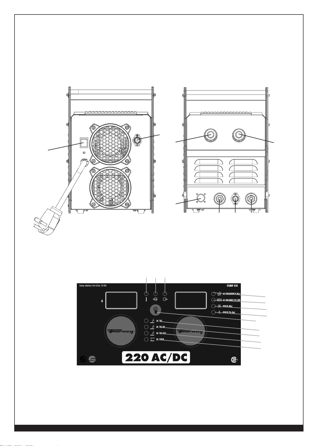
Your new single phase inverter welder offers Stick and TIG welding processes in the same power source. These processes
can be selected with the process SELECTOR BUTTON on the front panel of the unit.
TIG Welding
In the TIG position, a TIG torch with a gas valve in the handle is NOT required. The gas valve is automatically turned on
when pedal is pushed or torch trigger is engaged. The arc is activated using a lift arc technique or high frequency start
technique.
Using the AMPERAGE ADJUSTMENT KNOB, maximum welding current can be adjusted.
DC Stick Welding
Both rutile and basic electrodes can be welded. Welding current is adjusted using the AMPERAGE ADJUSTMENT KNOB.
Welder Layout and Controls
1. PROCESS SELECT SWITCH for the welding process selection:
a. AC TIG – Alternating Current TIG welding High Frequency.
b. DC TIG HF – Direct Current TIG High Frequency (automatic start when pedal or torch button engaged).
c. DC TIG LIFT – Direct Current TIG automatic start when touch and lifted to create arc.
d. DC STICK – Direct Current Stick welding.
2. THERMAL FAULT LED - thermal overload protection has been activated.
3. INPUT VOLTAGE LED – machine is powered on and operating normally.
4. OUTPUT FAULT LED – there is a general welding or machine fault.
5. AMPERAGE ADJUSTMENT KNOB is used to adjust the following welding parameters:
Using 120V
a. In STICK (“SMAW”) Mode it adjusts welding current (amperage) from 10A to 80A.
b. In TIG, (“GTAW”) Mode it adjusts welding current (amperage) from 5A to 130A.
Using 230V
a. In STICK (“SMAW”) Mode it adjusts welding current (amperage) from 10A-170A.
b. In TIG, (“GTAW”) Mode it adjusts welding current (amperage) from5A-200A.
6. SELECTOR SWITCH for the function selection:
a. AC Frequency (Hz) – Alternating Current Frequency in Hertz.
b. AC Balance (% EN) – Alternating Current % Electrode Negative.
c. PULSE (Hz) – Frequency: Pulses per second or Hertz.
d. PULSE (% On) – High/Low Balance: % at time Amperage Peak.
7. AMPHENOL – plug for the foot pedal or amptrol TIG torch (unit automatically detects accessory).
8. NEGATIVE (-) DINSE SOCKET – 35/50 dinse.
9. OUTPUT GAS.
10. POSITIVE (+) DINSE SOCKET - 35/50 dinse.
11. POWER SWITCH.
12. INPUT TIG GAS.
Advanced Function Selection (6) Details
1. AC (Hz) (6a): Normal AC frequency from the wall outlet is 60 Hz, which is the number of times the current
alternates between EN and EP in one second. A higher frequency (90-240 Hz) focuses the arc. A lower frequency (4090 Hz) softens the arc.
2. AC (% EN) (6B): Normal AC frequency spends 50% of the time in EN and 50% of the time in EP. Adjusting the
balance determines how long the polarity stays in EN. A higher percentage of EN (60-80%) creates a tighter arc, less
cleaning, and reduces tungsten balling. A lower percentage of EN (40-60%) creates a less-focused arc, more cleaning,
and will likely create a ball at the end of the tungsten.
12
WWW.FORNEYIND.COM
Page 13
3. PULSE (Hz) (6c): Changes how often amperage switches between Base Current and Peak (High) Current per
second. A higher pulse setting creates focused puddle and tight ripple bead pattern. A lower PPS creates broader
puddle and unique ripple bead pattern.
4. PULSE (% On) (6d): changes the amount of time the pulse stays at Main (Peak) current. A higher Pulse (% On) will
increase penetration while a lower value is better for thin material.
REAR VIEW OF FORNEY 220 AC/DC STICK/TIG ARC WELDER FRONT VIEW OF FORNEY 220 AC/DC STICK/TIG ARC WELDER
12
5
11
6
2 3 4
7
8 9 10
6a
6b
6c
6d
1
1a
1b
1c
1d
WWW.FORNEYIND.COM
13
Page 14
Operation
Performance Data Plate and Duty Cycle
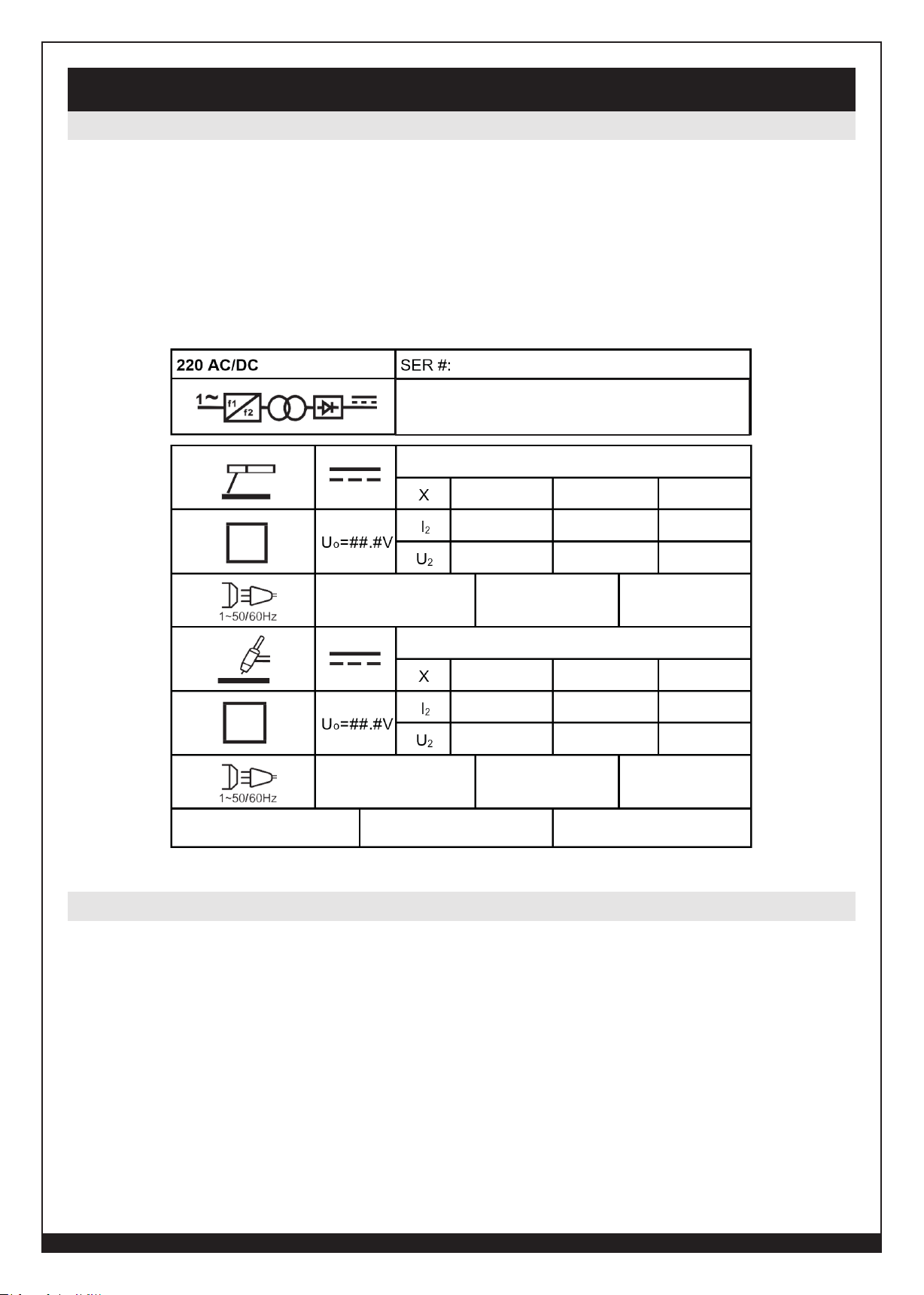
On the machine, there is a plate that includes all the operating specifications for your new unit. The serial number of the
product is also found on this plate.
The duty cycle rating of a welder defines how long the operator can weld and how long the welder must rest and be
cooled. Duty cycle is expressed as a percentage of 10 minutes and represents the maximum welding time allowed. The
balance of the 10-minute cycle is required for cooling.
For example, a welder has a duty cycle rating of 30% at the rated output of 90A. This means with that machine, you can
weld at 90 A output for three (3) minutes out of 10 with the remaining seven (7) minutes required for cooling. The duty
cycle of your new welder can be found on the data plate affixed to the machine. It looks like the diagram below. Referring
to the sample below, the “X” row lists duty cycle percentages while the “I2” row lists the
amp draw corresponding to the duty cycle. Various duty cycles at other amperages are listed on your data plate.
Internal Thermal Protection
If you exceed the duty cycle of the welder, the thermal protection system will engage, shutting off all welder output. After
cooling, the thermal protector will automatically reset and the welding functions can resume. This is normal and automatic
behavior of the machine, and does not require any user action. However, you should wait at least ten minutes after the
thermal protector engages before resuming welding. You must do this even if the thermal protector resets itself before the
ten minutes is up or you may experience less than specified duty cycle performance.
CAUTION: DO NOT REGULARLY EXCEED THE DUTY CYCLE OR DAMAGE TO THE WELDER
CAN RESULT.
14
IP21S
(Example Data Plate)
WWW.FORNEYIND.COM
Page 15
Welding Preparation
An important factor in making a satisfactory weld is preparation. This includes studying the process and equipment and
practicing welding before attempting to weld finished product. An organized, safe, ergonomic, comfortable, and well-lit
work area should be prepared for the operator. The work area should specifically be free of all flammables with both a
fire extinguisher and a bucket of sand available.
To properly prepare for welding with your new welder, it is necessary to:
• Read the safety precautions at the front of this manual.
• Prepare an organized, well-lit work area.
• Provide protection for the eyes and skin of the operator and bystanders.
• Attach the ground clamp to the bare metal to be welded, making sure of good contact.
• Plug the machine into a suitable outlet.
• Completely open the gas cylinder valve. Adjust the gas pressure regulator to the correct flow rate. (Not applicable to
Stick “SMAW” process).
EXPOSURE TO A WELDING ARC IS EXTREMELY HARMFUL TO THE EYES AND SKIN.
PROLONGED EXPOSURE TO A WELDING ARC CAN CAUSE BLINDNESS AND BURNS. NEVER
STRIKE AN ARC OR BEGIN WELDING UNLESS YOU ARE ADEQUATELY PROTECTED. WEAR
FIRE RESISTANT WELDING GLOVES, HEAVY LONG SLEEVED SHIRT, CUFFLESS PANTS; HIGH
TOPPED SHOES AND A WELDING HELMET.
Setup for Stick Welding (SMAW)
• Using the PROCESS SELECTOR BUTTON on the front panel to choose DC Stick (d) option.
• Check the electrode packaging to determine the recommended polarity and connect the electrode holder and ground
clamp to the POSITIVE (+) and NEGATIVE (-) DINSE SOCKETS accordingly.
• Direct current electrode positive (DCEP) or direct current reverse polarity (DCRP): electrode holder in POSITIVE (+)
DINSE SOCKET, ground clamp in NEGATIVE (-) DINSE SOCKET. Most electrodes use DCEP.
• Direct current electrode negative (DCEN) or direct current straight polarity (DCSP): electrode holder in NEGATIVE (-)
DINSE SOCKET, ground clamp in POSITIVE (+) DINSE SOCKET.
• Ensure the ground clamp has a good connection to the workpiece and is connected on clean, bare metal (not rusty or
painted).
• Secure the bare end of the welding electrode in-to the jaws of the electrode holder.
• Switch the unit ON with the ON/OFF SWITCH.
• Set the amperage with the AMPERAGE ADJUSTMENT KNOB.
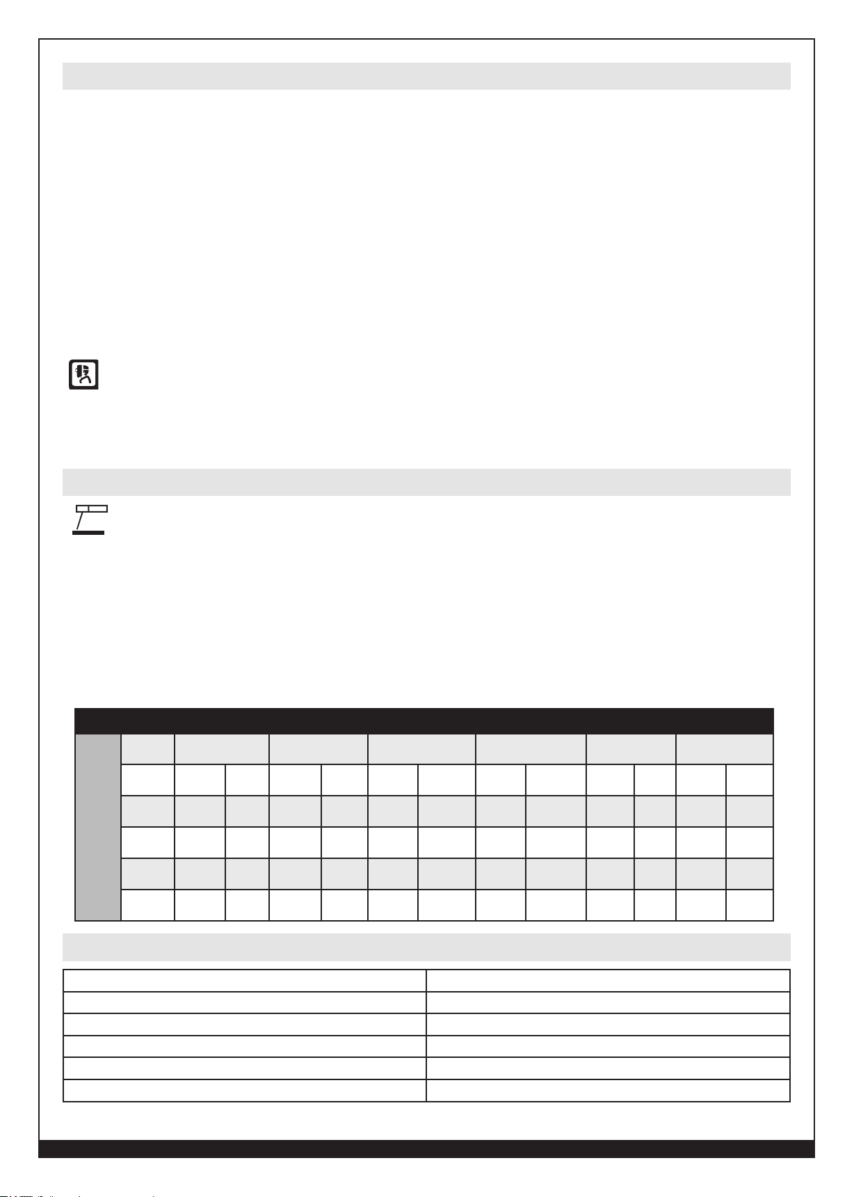
220 AC/DC STICK SET-UP CHART
STICK
(SMAW)
Electrode
Type
Electrode
Diam
1/16"
(1.6mm)
3/32"
(2.4mm)
1/8"
(3.2mm)
5/32"
(4.0mm)
E6010 E6011 E6013 E7014 E7018 E308L/E309L/E316L
Amperage Polarity Amperage Polarity Amperage Polarity Amperage Polarity Amperage Polarity Amperage Polarity
N/A DCEP N/A AC-DCEP 20-45 AC-DCEP-DCEN N/A AC-DCEP-DCEN N/A DCEP 20-40 DCEP
30-75 DCEP 40-85 AC-DCEP 40-90 AC-DCEP-DCEN 70-90 AC-DCEP-DCEN 65-100 DCEP 40-70 DCEP
75-125 DCEP 75-125 AC-DCEP 70-110 AC-DCEP-DCEN 90-140 AC-DCEP-DCEN 110-165 DCEP 75-115 DCEP
110-165 DCEP 110-165 AC-DCEP 115-140 AC-DCEP-DCEN 140-190 AC-DCEP-DCEN 150-220 DCEP 105-160 DCEP
Recommended Amperage Settings (SMAW)
1 /16” - 16 Gauge 30-40
5 /64” – 14 Gauge 50-65
3 /32” 70-100
1 /8” 100-140
5 /32” 140-180
3 /16” 150-220
WWW.FORNEYIND.COM
15
Page 16
Setup for TIG Welding (GTAW)
Setting up the Equipment for TIG Welding (GTAW):
Lanthanated Tungsten 1/16” to 1/8” (MAX) recommended for use.
WARNING: TIG TORCH IS ALWAYS LIVE (ELECTRICALLY HOT).
Use caution and ensure the TIG torch is not in contact with or near conductive or grounded materials.
• Connect the TIG torch cable to the NEGATIVE (-) DINSE SOCKET (8) of the welder.
• Connect the ground cable connector to the POSITIVE (+) DINSE SOCKET (10) of the welder.
• Ensure the ground clamp has a good connection to the workpiece and is connected on clean, bare metal (not rusty or
painted).
• Connect the TIG torch gas line to the gas regulator (argon gas or argon/helium).
INERT GAS (ARGON OR ARGON/HELIUM) ONLY.
TURN ON GAS AT THE GAS REGULATOR, CHECK FOR GAS FLOW AND ADJUST FLOW RATE
AS NEEDED.
• Fix the tungsten electrode so that it protrudes approximately ¼ inch from the torch nozzle.
• Ensure the TIG torch is safely away from all conductive materials.
• Switch the unit ON with the POWER SWITCH.
• Using the PROCESS SELECTOR BUTTON on the front panel to choose which TIG option needed: AC TIG (1a), DC TIG
HF (1b), or DC TIG LIFT (1c).
• Set the amperage with the SECONDARY PARAMETER KNOB/SELECTOR.
• Set the max amperage with the AMPERAGE ADJUSTMENT KNOB
• Press pedal or torch button.
• Initiate the weld arc.
• Use pedal or torch to adjust output amperage while working.
TIG
(AC)
(GTAW)
100%
Argon
TIG
(DC)
(GTAW)
100%
Argon
REMEMBER TO CLOSE THE VALVE ON THE GAS CYLINDER IMMEDIATELY AFTER ALL WELDING
IS COMPLETED.
220 AC TIG SET-UP CHART
DCEN
Material
Thickness
DCEN
-Recommend
2%
Certiated
Tungsten
Filler
Diameter
1/16"
(1.6mm)
1/16" (1.6mm) 3/32" (2.4mm) 1/8" (3.2mm) 3/16" (4.8mm)
Gas
Amperage
50-80
Cup
3/8"
(#6)
Tungsten
(1.6mm)
Diam
1/16"
Filler
Diameter
1/16"
(1.6mm)
Amperage
80-110
Gas
Cup
3/8"
(#6)
Tungsten
Diam
1/16"
(1.6mm)
Filler
Diameter
3/32"
(2.4mm)
Amperage
85-120
Gas
Cup
3/8"
(#6)
Tungsten
Diam
1/16:
(1.6mm)
Filler
Diameter
1/8"
(3.2mm)
Amperage
125-200
Gas
Cup
7/16"
(#7)
Tungsten
Diam
3/32"
(2.4mm)
Polarity
220 DC TIG SET-UP CHART
DCEN
Material
Thickness
DCEN
-Recommend
2%
Certiated
Tungsten
Filler
Diameter
1/16"
(1.6mm)
1/16" (1.6mm) 1/8" (3.2mm) 3/16" (4.8mm) 1/4" (6.4mm)
Gas
Amperage
50-80
Cup
3/8"
(#6)
Tungsten
(1.6mm)
Diam
1/16"
Filler
Diameter
1/16"
(1.6mm)
Amperage
80-110
Gas
Cup
3/8"
(#6)
Tungsten
Diam
1/16"
(1.6mm)
Filler
Diameter
3/32"
(2.4mm)
Amperage
85-120
Gas
Cup
3/8"
(#6)
Tungsten
Diam
1/16:
(1.6mm)
Filler
Diameter
1/8"
(3.2mm)
Amperage
125-200
Gas
Cup
7/16"
(#7)
Tungsten
Diam
3/32"
(2.4mm)
Polarity
Welding Tips:
• Always weld clean, dry and well-prepared material.
• Move the torch smoothly and steadily as you weld.
• Avoid welding in very drafty areas. A weak, pitted and porous weld will result due to drafts blowing away the
protective welding gas.
• Sharp bends or kinks in the welding cable should be avoided.
• The diameter of the welding electrode should be approximately the same as the thickness of the metal to be welded.
• The packaging of the welding electrode typically gives a recommended range for the welding current. Set the
amperage accordingly.
16
WWW.FORNEYIND.COM
Page 17
Gas Selection
Use 100% argon gas when TIG welding.
Accessory Connection Guide
This machine has a 7-pin Amphenol™ style connection for connecting accessories16
• Foot Pedal (adjusts amperage) – attach TIG torch to negative Dinse™ terminal and then plug in 7-pin foot pedal
connector.
• Double check the TIG process is selected.
• Set desired maximum current on the machine.
• Use pedal to fine control amperage.
• Amperage controlled TIG torch – attach TIG torch to negative Dinse™ terminal and then plug in 7-pin connector.
• Double check the TIG process is selected.
• Set desired maximum current on the machine.
• Use roller wheel on the TIG torch to fine control amperage.
Tungsten Recommendations
TUNGSTEN TYPE COMMENTS
1.5-2% Lanthanated (La) Most versatile tungsten (best overall)
1.5-2% Ceriated (Ce) Solid performance for most applications
1-2% Thoriated (Th) Performance OK but hazardous
Pure Ok but will ball up and not allow concentrated arc
Recommended Amperage Settings for SMAW (Arc) Electrodes
SIZE OF WELDING ELECTRODE AMPERAGE SETTING
1 / 16” – 16 Gauge 30-40
5 / 64” – 14 Gauge 50-65
3 / 32” 70-100
1 / 8 “ 100-140
5 / 32” 140-180
3 / 16” 150-200
Recommended Amperage & Electrode Types for TIG Welding
TUNGSTEN DCEN (Th,La,Ce) AC (La,Ce) AC (Pure)
.040” 10-50A 20-40A N/A
1 / 16” 40-120A 30-170A 30-90A
3 / 32” 90-200A 60-180A 40-120A
1 / 8” 150A+ 130A+ 100-200A
WWW.FORNEYIND.COM
17
Page 18
A Good Starting Point for Aluminum TIG
< 1/8 “ = 140 MAX
Amperage
1/8 “ – 3 /16” = 170 MAX
1 /4” + = 200 MAX
6a AC Freq 90 HZ
6b AC Balance 70 % EN
6c PULSE (HZ) 1
6d PULSE ( % ON) 50%
Maintenance & Servicing
General Maintenance
This welder has been engineered to need minimal service providing that a few very simple steps are taken to properly
maintain it.
1. Replace INPUT POWER CABLE, ground cable, ground clamp, or torch/electrode cable when damaged or worn.
2. Avoid directing grinding particles towards the welder. These conductive particles can build up inside the machine and
cause severe damage.
3. Periodically clean dust, dirt, grease, etc. from your welder. Every six months or as necessary, remove the side panels
from the welder and use compressed air to blow out any dust and dirt that may have accumulated inside the welder.
WARNING: DISCONNECT FROM POWER SOURCE WHEN CARRYING OUT THIS OPERATION.
4. Check all cables periodically. They must be in good condition and not cracked.
WARNING: ELECTRIC SHOCK CAN KILL! Be aware that the POWER SWITCH, when OFF, does not remove
power from all internal circuitry in the welder. To reduce the risk of electric shock, always unplug the welder from its AC
power source and wait several minutes for electrical energy to discharge before removing side panels.
Troubleshooting
The following is a troubleshooting table provided to help you determine a possible remedy when you are
having a problem with your welder.
This table does not provide all possible solutions, only those possibilities considered likely to be common
faults.
PROBLEM
All LEDs OFF.
No output power, Fan not
operating.
FAULT CODE F01 DISPLAYED.
FAULT CODE F02 DISPLAYED.
POSSIBLE CAUSE POSSIBLE SOLUTION
No input power. Connect machine to proper input power
source.
POWER SWITCH is OFF. Ensure POWER SWITCH (rear) is in the ON
position.
Exceeded duty cycle; thermal protector
engaged.
POWER SWITCH is OFF. Ensure POWER SWITCH (rear) is in the ON
No voltage or incorrect voltage supplied to
welder.
Verify that circuit breaker has not been tripped
in your main power panel. Reset if needed.
position.
Make sure the machine is plugged in. Check
the status of your INPUT VOLTAGE INDICATOR
LED. It should be illuminated. Check the voltage
of your outlet. If it is 10% more or less than
120V or 230V, call a qualified electrician.
FAULT CODE F05 DISPLAYED.
18
Torch triggered before machine is ready Torch triggered or turned on before
machine is powered on will fault. Release
torch trigger and machine will reset within
five seconds
WWW.FORNEYIND.COM
Page 19
PROBLEM
POSSIBLE CAUSE POSSIBLE SOLUTION
FAULT CODE F09 DISPLAYED.
No INDICATOR LED is
illuminated and nothing works
on the welder.
Low output or non-penetrating
weld.
Output short or abnormal voltage
feedback.
Stick electrode stuck to work piece Make sure that your stick electrode is not
Machine is not turned ON. Turn machine ON with ON/OFF SWITCH.
No input power present. Make sure machine is plugged in.
Weld parameters too low. Adjust welding parameters
Too long or improper extension cord. Use a proper extension cord (#12 AWG
Poor ground connection or torch/electrode
connection.
Make sure the MIG wire is not touching
the grounded work piece.
Make sure the TIG electrode is not
touching the grounded work piece.
stuck to the grounded work piece.
Verify that circuit breaker has not been
tripped. Reset if needed.
Verify output power from the outlet.
Do not use the machine on a GFI outlet.
wire or heavier, no longer than 25 ft.). See
“Extension Cords”, page 11.
Reposition clamp and check cable to
clamp connection.
Check connection of ground cable, torch
or electrode holder
Ground clamp, ground cable,
and/or welding cable get hot.
FREQUENT CIRCUIT BREAKER
TRIPS
Input power too low. Have a qualified electrician verify the
voltage at your outlet. If the voltage is
appropriate, verify that the circuit wiring is
sufficient for the circuit breaker size.
Bad ground or loose ground connection. Check connection of ground cable, torch
or electrode holder.
Check connection of the ground cable
to the ground clamp. Tighten cable
connection to ground clamp if needed.
Ensure the connection between the ground
clamp and workpiece is good and on
clean, bare (not painted or rusted) metal.
Make sure cable is not damaged.
Machine is drawing too much amperage
due to use of larger size electrode.
Machine is not the only piece of electrical
equipment on the circuit.
Circuit breaker is incorrect/insufficient for
use with this machine.
Use a smaller electrode.
Make sure the welder is on a dedicated
circuit or is the only thing plugged into a
circuit.
Verify that the circuit breaker for the circuit
is a 20A time-delay (slow-blow) breaker
for 120V and a 50A for 230V. If it is not,
have a qualified electrician install the
proper breakers.
WWW.FORNEYIND.COM
19
Page 20
PROBLEM
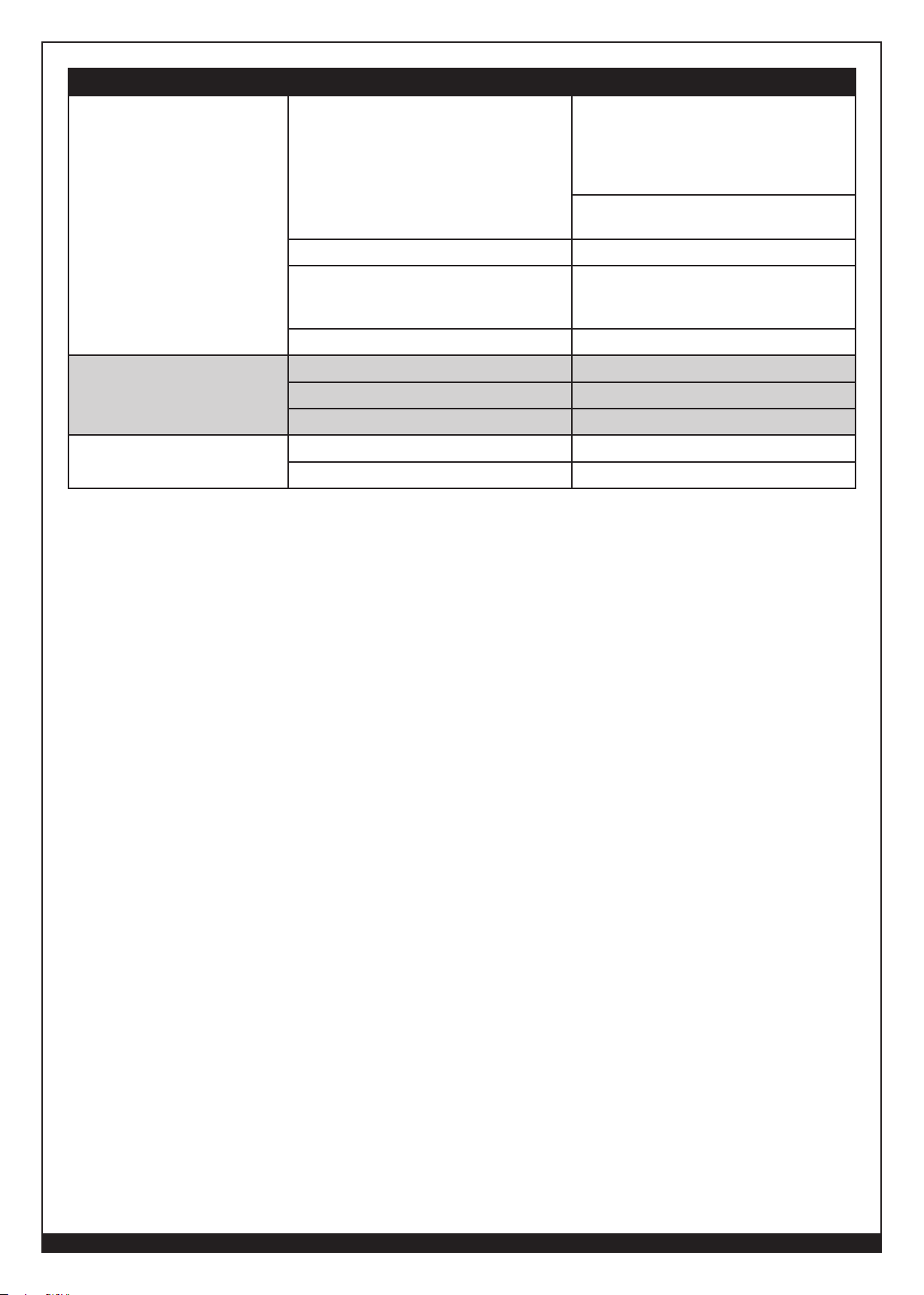
Poor quality welds.
POSSIBLE CAUSE POSSIBLE SOLUTION
Insufficient gas at weld area. Check that the gas is not being blown
away by drafts and, if so, move to a more
sheltered weld area. If not, check gas
cylinder contents, gauge, regulator setting,
and operation of gas valve.
Make sure gas connections are tight and
there are no leaks
Rusty, painted, oily or greasy workpiece. Ensure workpiece is clean and dry.
Difficult arc start.
Arc is wandering (TIG).
Poor ground connection or torch/electrode
connection.
Incorrect settings. Check welding parameters and polarity.
Amperage is too low. Increase amperage setting.
Make sure base metal is clean. Properly clean base metal.
Make sure electrode is not damaged. Replace electrode if needed.
Tungsten is too large. Use a smaller tungsten.
Gas flow is too high. Reduce gas flow.
Check ground clamp/workpiece
connection and all connections to the
machine.
20
WWW.FORNEYIND.COM
Page 21
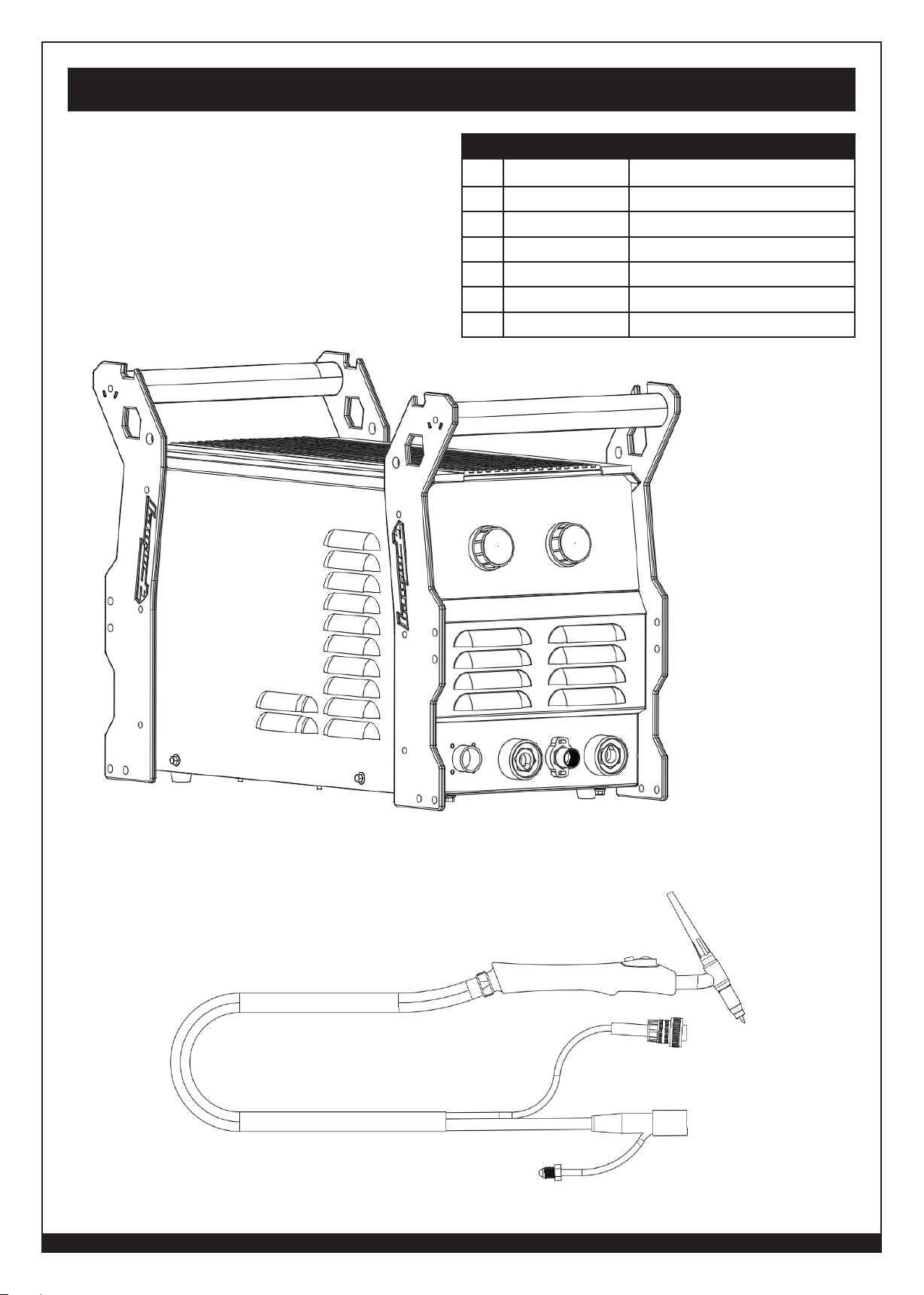
Machine Parts Diagram & Replacement Parts List
NO. PART NUMBER ITEM DESCRIPTION
1
2 85516 120-230 Volt Power Adapter Plug
3 85655 TIG Foot Pedal
4 85658 Standard TIG Torch
5 85668 Ground Clamp and Cable
6 85670 Electrode Holder with Cable
7 5084 Expert-Tech Tool
85364
Argon/Co2 Flow Meter
WWW.FORNEYIND.COM
21
Page 22

User Notes
_______________________________________________________________________________________________
________________________________________________________________________________
________________________________________________________________________________
________________________________________________________________________________
________________________________________________________________________________
________________________________________________________________________________
________________________________________________________________________________
________________________________________________________________________________
________________________________________________________________________________
________________________________________________________________________________
________________________________________________________________________________
________________________________________________________________________________
________________________________________________________________________________
________________________________________________________________________________
________________________________________________________________________________
________________________________________________________________________________
________________________________________________________________________________
________________________________________________________________________________
________________________________________________________________________________
________________________________________________________________________________
________________________________________________________________________________
________________________________________________________________________________
________________________________________________________________________________
________________________________________________________________________________
________________________________________________________________________________
________________________________________________________________________________
________________________________________________________________________________
________________________________________________________________________________
________________________________________________________________________________
________________________________________________________________________________
________________________________________________________________________________
________________________________________________________________________________
________________________________________________________________________________
________________________________________________________________________________
________________________________________________________________________________
________________________________________________________________________________
________________________________________________________________________________
________________________________________________________________________________
________________________________________________________________________________
________________________________________________________________________________
________________________________________________________________________________
________________________________________________________________________________
________________________________________________________________________________
________________________________________________________________________________
________________________________________________________________________________
________________________________________________________________________________
________________________________________________________________________________
________________________________________________________________________________
________________________________________________________________________________
________________________________________________________________________________
________________________________________________________________________________
22
WWW.FORNEYIND.COM
Page 23

User Notes
_______________________________________________________________________________________________
________________________________________________________________________________
________________________________________________________________________________
________________________________________________________________________________
________________________________________________________________________________
________________________________________________________________________________
________________________________________________________________________________
________________________________________________________________________________
________________________________________________________________________________
________________________________________________________________________________
________________________________________________________________________________
________________________________________________________________________________
________________________________________________________________________________
________________________________________________________________________________
________________________________________________________________________________
________________________________________________________________________________
________________________________________________________________________________
________________________________________________________________________________
________________________________________________________________________________
________________________________________________________________________________
________________________________________________________________________________
________________________________________________________________________________
________________________________________________________________________________
________________________________________________________________________________
________________________________________________________________________________
________________________________________________________________________________
________________________________________________________________________________
________________________________________________________________________________
________________________________________________________________________________
________________________________________________________________________________
________________________________________________________________________________
________________________________________________________________________________
________________________________________________________________________________
________________________________________________________________________________
________________________________________________________________________________
________________________________________________________________________________
________________________________________________________________________________
________________________________________________________________________________
________________________________________________________________________________
________________________________________________________________________________
________________________________________________________________________________
________________________________________________________________________________
________________________________________________________________________________
________________________________________________________________________________
________________________________________________________________________________
________________________________________________________________________________
________________________________________________________________________________
________________________________________________________________________________
________________________________________________________________________________
________________________________________________________________________________
________________________________________________________________________________
WWW.FORNEYIND.COM
23
Page 24

Forney Industries, Inc.
2057 Vermont Drive
Fort Collins, CO 80525
+1-800-521-6038
www.forneyind.com
 Loading...