

Ford Transit 1-Way Tipper Supplementary Owner's Handbook

1 Way Hand Book Nov'14:11-12 Seat Transit 28/11/14 11:13 Page 1
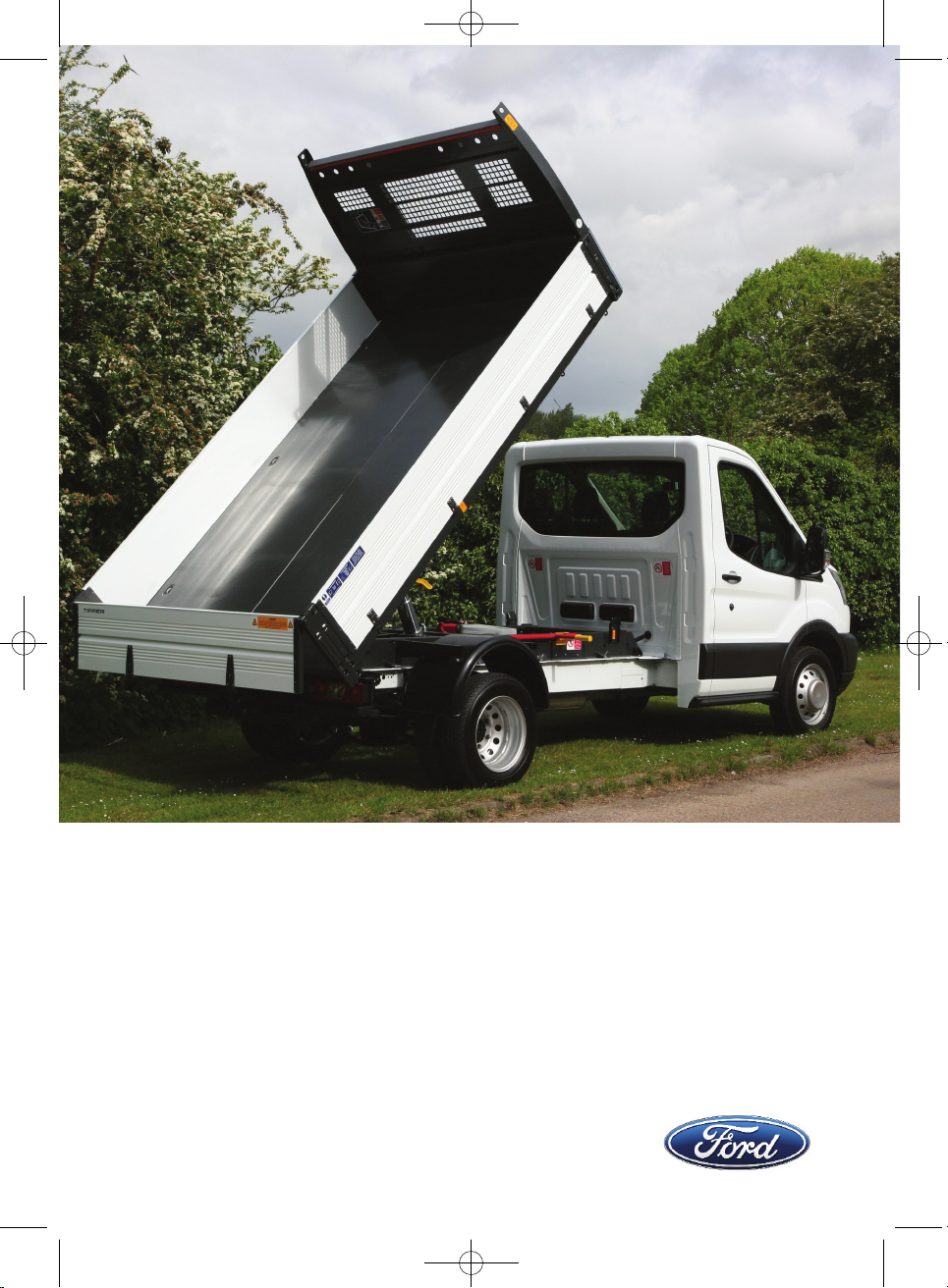
Supplementary Owner's Handbook
Ford Transit 1Way Tipper
December 2014 on
1 Way Hand Book Nov'14:11-12 Seat Transit 28/11/14 11:13 Page 2

The illustrations, technical information, data and descriptions contained in this publication, were correct
at the time of going to print. VFS (Southampton) Ltd reserve the right to make any changes necessary
in line with continuous development and improvement.
No liability can be accepted for any inaccuracies or omissions in this publication, although due care
has been taken to make it as complete and accurate as possible.
The publication may not be duplicated, reprinted, stored in a data processing system or transmitted
by electronic, mechanical, photographic or other means, or recorded, translated, edited, abridged or
expanded without the prior written consent of VFS (Southampton) Ltd.
The same also applies for parts of this manual and their use in other publications.
© Copyright 2014, issued by VFS (Southampton) Ltd. Part No: VFS01111492 issue 2
December 2014
1 Way Hand Book Nov'14:11-12 Seat Transit 28/11/14 11:13 Page 3

Table of Contents
1
Table of Contents
Introduction
About this Handbook . . . . . . . . . . . .2
Symbols Glossary . . . . . . . . . . . . . . .2
Parts and Accessories . . . . . . . . . . .3
Safety First . . . . . . . . . . . . . . . . . . . . .3
Warranty . . . . . . . . . . . . . . . . . . . . . . .4
Quick Start
Quick Start . . . . . . . . . . . . . . . . . . . . .5
Tipper Controls
Tailboard . . . . . . . . . . . . . . . . . . . . . .12
Sideboards . . . . . . . . . . . . . . . . . . . .16
Tipper Control Station . . . . . . . . . . .18
Isolation Switch . . . . . . . . . . . . . . . .19
Emergency Stop Switch . . . . . . . . .21
Warning LED . . . . . . . . . . . . . . . . . .22
Buzzers . . . . . . . . . . . . . . . . . . . . . . .23
Body Prop . . . . . . . . . . . . . . . . . . . .25
Manual Lowering Valve . . . . . . . . .27
Load Carrying
General Information . . . . . . . . . . . .28
Loading . . . . . . . . . . . . . . . . . . . . . . .28
Load Distribution . . . . . . . . . . . . . . .29
Load Retention and Sheeting . . . .30
Tipping
Tipping . . . . . . . . . . . . . . . . . . . . . . . .31
Maintenance
Daily Driver Checks . . . . . . . . . . . . .35
Monthly Maintenance Checks . . .36
Annual Maintenance Checks . . . .37
Hydraulic Oil Level Check . . . . . . .38
Hydraulic Body Latch Check . . . .39
Electrical
Fuse Locations . . . . . . . . . . . . . . . .42
Fuse Replacement . . . . . . . . . . . . .43
Vehicle Care
Cleaning the Exterior . . . . . . . . . . .44
Repairing Minor Paint Damage . . .44
Towing
Tailboard Protection . . . . . . . . . . . .45
Lighting
Changing a Lamp . . . . . . . . . . . . . .46
Emergency Equipment
Warning Triangle . . . . . . . . . . . . . . .47
Vehicle Identification
Vehicle Identification . . . . . . . . . . . .48
Index
Index . . . . . . . . . . . . . . . . . . . . . . . . .50
Notes . . . . . . . . . . . . . . . . . . . . . . . . .53
1 Way Hand Book Nov'14:11-12 Seat Transit 28/11/14 11:13 Page 4
Introduction
2
ABOUT THIS HANDBOOK
This supplementary Owners Handbook must be referred to in addition to the
standard Transit Owner’s Handbook. Read and understand both manuals and
familiarise yourself with the vehicle before operating the vehicle on the road.
Note: This handbook only details the features on the Transit 1Way Tipper that
are not covered in the standard Transit Owners Handbook, therefore it is
imperative that this supplementary handbook is kept with the standard Transit
Owner’s Handbook.
Note: Always use and operate your vehicle in line with all applicable laws and
regulations.
Note: Pass on this handbook when selling your vehicle; it is an integral part of
the vehicle.
SYMBOLS GLOSSARY
Symbols in this handbook
You risk death or serious injury to yourself and others if you do not
follow the instructions highlighted by the warning symbol.
When you see this symbol, read and follow the relevant instructions in
this handbook.
You risk damaging your vehicle if you do not follow the instructions
highlighted by the caution symbol.
WARNING
CAUTION
1 Way Hand Book Nov'14:11-12 Seat Transit 28/11/14 11:13 Page 5
Introduction
PARTS AND ACCESSORIES
Spare parts and Accessories are available from: VFS (Southampton) Ltd,
Unit 8, Barton Park Industrial Estate, Chickenhall Lane, Eastleigh SO50 6RR
Tel: 023 8065 1704 • Fax: 023 8062 0999 • Email: parts@vfs.co.uk
Detailed information can be found in the Spare Parts and Accessories
catalogue. Available on line at www.vfs.co.uk. All maintenance and repairs
should be logged in the section provided within the Spare Parts and
Accessories catalogue.
SAFETY FIRST!
Tipping is a potentially hazardous operation. It is essential that all
operators fully understand the procedures detailed in this handbook
and are aware of the Tipper controls on the vehicle. Health and Safety
legislation must be strictly applied. UK Construction & Use Regulations
must be observed when operating the vehicle on the public highway.
The basis for Health and Safety law in the UK is the Health and Safety at Work
Act 1974 and its amendments. However certain EU Law is now applicable; all
of which must be complied with before, during and after the use of this vehicle
and the Tipper bodywork supplied with it. The Tipper bodywork supplied with
this vehicle is recognised as a machine, therefore Health and Safety legislation
applicable to machinery must be recognised in addition to general Health and
Safety law.
It is the responsibility of the Driver, Owner and/or Operator to establish what
Health and Safety legislation applies when using this vehicle and that only persons
trained and qualified in line with that legislation be allowed to use this machine.
Depending on the circumstances and the territory that the vehicle is being used,
other legislation may apply. Always check that existing legislation has not been
updated or superseded, and whether new legislation has been introduced.
3
WARNING
1 Way Hand Book Nov'14:11-12 Seat Transit 28/11/14 11:13 Page 6

Introduction
WARRANTY
Full warranty exists on all parts and workmanship associated with the Tipper
body conversion for 3years / 100,000 miles. Warranty is only valid if the Tipper
is operated in accordance with the Supplementary Owner’s Handbook and
current Road Traffic Act Legislation.
Warranty claims for parts associated with the Tipper body conversion should
be made direct to VFS (Southampton) Ltd.
VFS (Southampton) Ltd.
Unit 8
Barton Park Industrial Estate
Chickenhall lane
Eastleigh
Hants
SO50 6RR
Tel: 023 8065 1704
Fax: 023 8062 0999
Email: parts@vfs.co.uk
4
1 Way Hand Book Nov'14:11-12 Seat Transit 28/11/14 11:13 Page 7
5
This quick start guide is intended to refresh operators of the
control layout, operation and loading of the vehicle only after the
entire handbook has been read and understood.
Tipping is a potentially hazardous operation. Ensure full familiarisation
of all Controls has been achieved in addition to reading and
understanding this manual before attempting to operate this vehicle.
If in any doubt do not attempt to operate the Tipper.
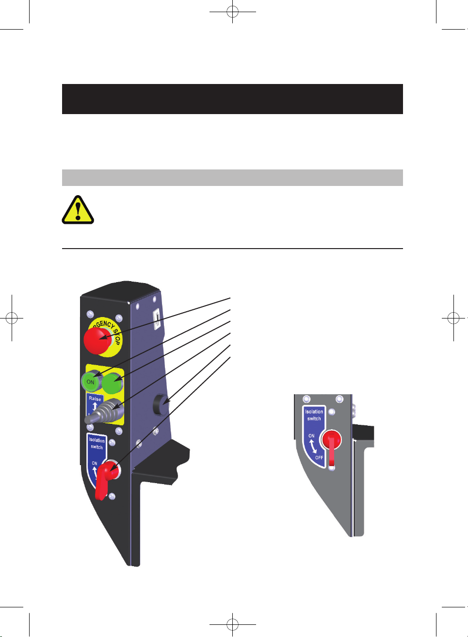
Tipper Control Module:
• Emergency stop button
• Power on switch
• Power indicator lamp
• Raise/lower joystick
• Audible warning buzzer
• On/Off isolation Switch
QUICK START
WARNING
Controls Layout – InCab
Isolation Switch
•On/Off
1 Way Hand Book Nov'14:11-12 Seat Transit 28/11/14 11:13 Page 8
6
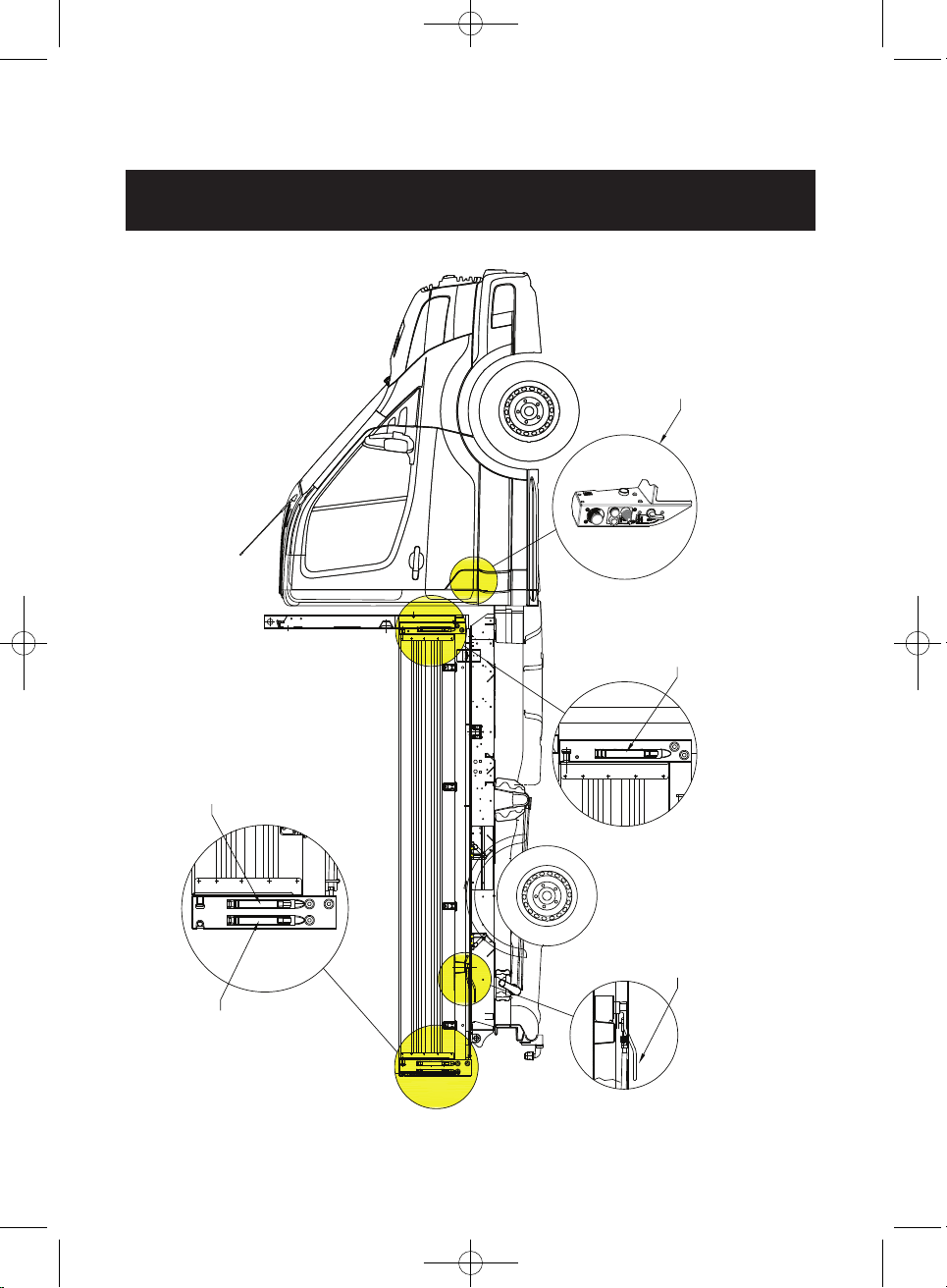
Controls Layout Body
QUICK START
1 Way Hand Book Nov'14:11-12 Seat Transit 28/11/14 11:13 Page 9
Tipper
Control Station
Sideboard
Release Latch
Sideboard
Release Latch
Tailboard Lower
Latch Release
Tip-Over Latch

7
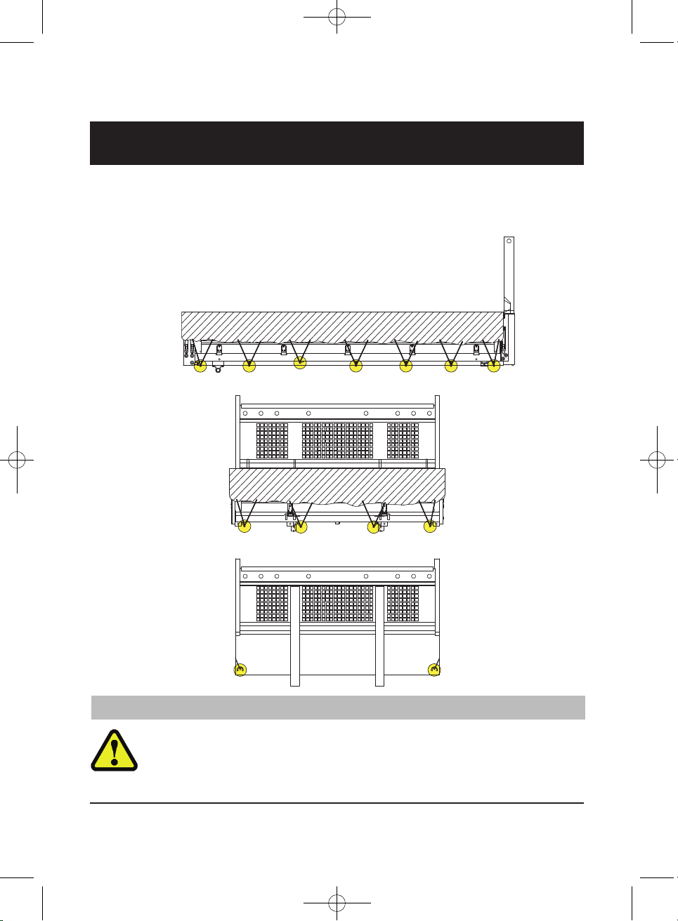
Loading The Tipper
Ensure the load is uniformly distributed across the Tipper bed.
All loads must be secured and restrained before operating the vehicle
on the public highway. Failure to adequately restrain the payload
present a hazard to other road users and is in contravention of the UK
Construction and Use Regulations.
Maximum gantry load – Refer to decal on cab protector.
CORRECT LOAD
DISTRIBUTION
INCORRECT LOAD DISTRIBUTION
QUICK START
WARNING
1 Way Hand Book Nov'14:11-12 Seat Transit 28/11/14 11:13 Page 10

8
Load Retention – Load Anchorage Points
Used for non fluid loads. Always ensure that all items are secured before
attempting to drive the vehicle. Do not tip with the items lashed down to the
anchorage points.
Refer to decal on cab protector for load anchorage ratings. Do not
exceed the maximum Gross Vehicle Mass (GVM) or individual front
and rear axle capacities. Refer to the Vehicle identification section in
the Ford Transit Owner’s Handbook.
QUICK START
WARNING
1 Way Hand Book Nov'14:11-12 Seat Transit 28/11/14 11:13 Page 11
9
QUICK START
Load Sheeting – Sheeting Hooks
It is recommended that all 'Fluid' loads for example Sand, Gravel, Soil, Wood
Chippings etc, are sheeted to prevent a hazard to other road users.
Refer to decal on cab protector for load anchorage ratings.
Do not use sheeting hooks to anchor loads.
WARNING
1 Way Hand Book Nov'14:11-12 Seat Transit 28/11/14 11:13 Page 12
10
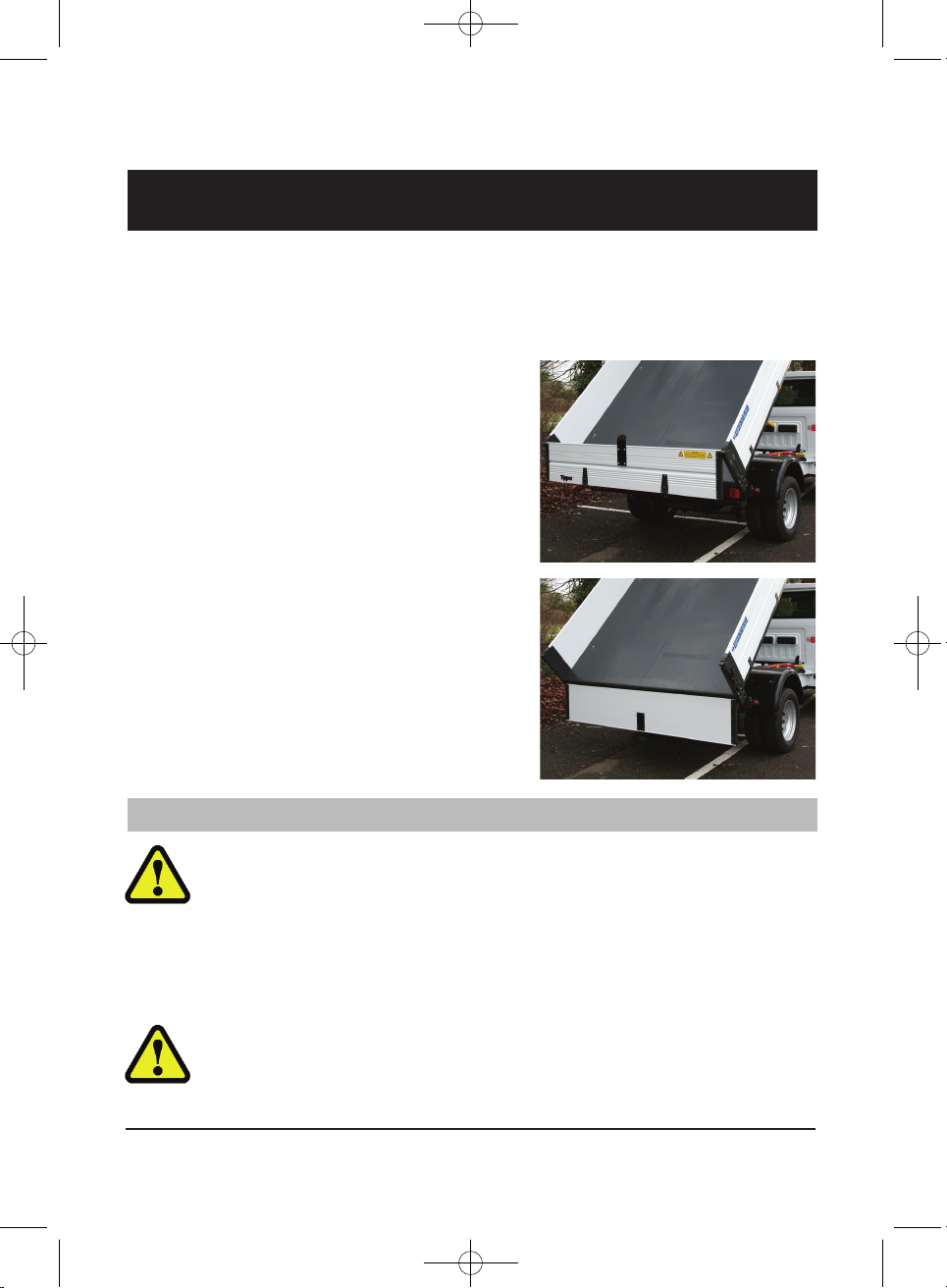
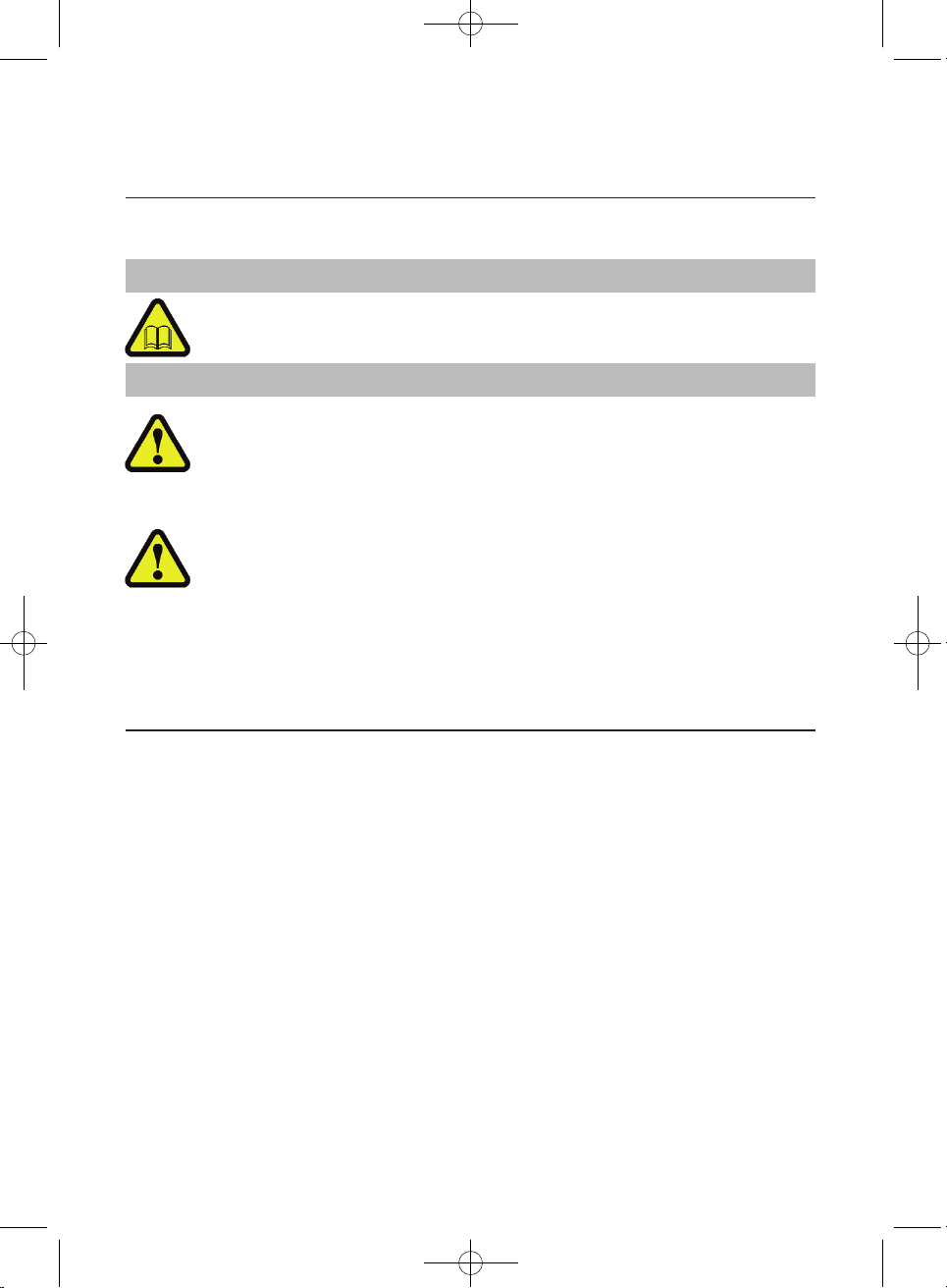
Rear Tailboard configuration – establish correct mode before
attempting to tip:
Dependent upon the type of load being tipped the dual mode tailboard can be
configured to open in one of two ways:
1) Top Hinged (TipThru) – best suited for
‘Fluid’ loads such as sand, gravel,
crushed concrete, type 1 aggregate,
soil, wood shavings etc.
2) Bottom Hinged (TipOver) – best
suited for loads consisting of one or
more large individual items for
example logs, tree cuttings, white
goods, furniture etc.
If in doubt, use the Bottom Hinged mode.
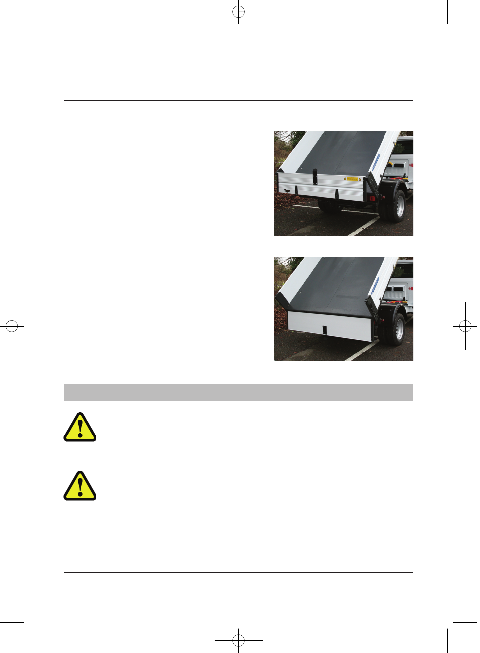
Bottom Hinged mode Always ensure sufficient clearance for the
tailboard to hang without touching the ground, a minimum of 12"
(300mm) is recommended with the tailboard in the lowered condition
body fully laden and in the lowered position.
If a tow bar has been fitted, ensure that the tailboard has been fitted
with a protective guide (see Towing) to prevent it from jamming on the
tow hitch. If a guide is not installed the tailboard may be damaged.
Bottom Hinged mode – Vehicle rear lights and hazard lights will be
obscured, always deploy additional warnings to other road users and
minimise the amount of time the board is lowered, return board to the
shut position immediately after the tip is completed.
QUICK START
WARNING
1 Way Hand Book Nov'14:11-12 Seat Transit 28/11/14 11:13 Page 13
11
QUICK START
Tipping
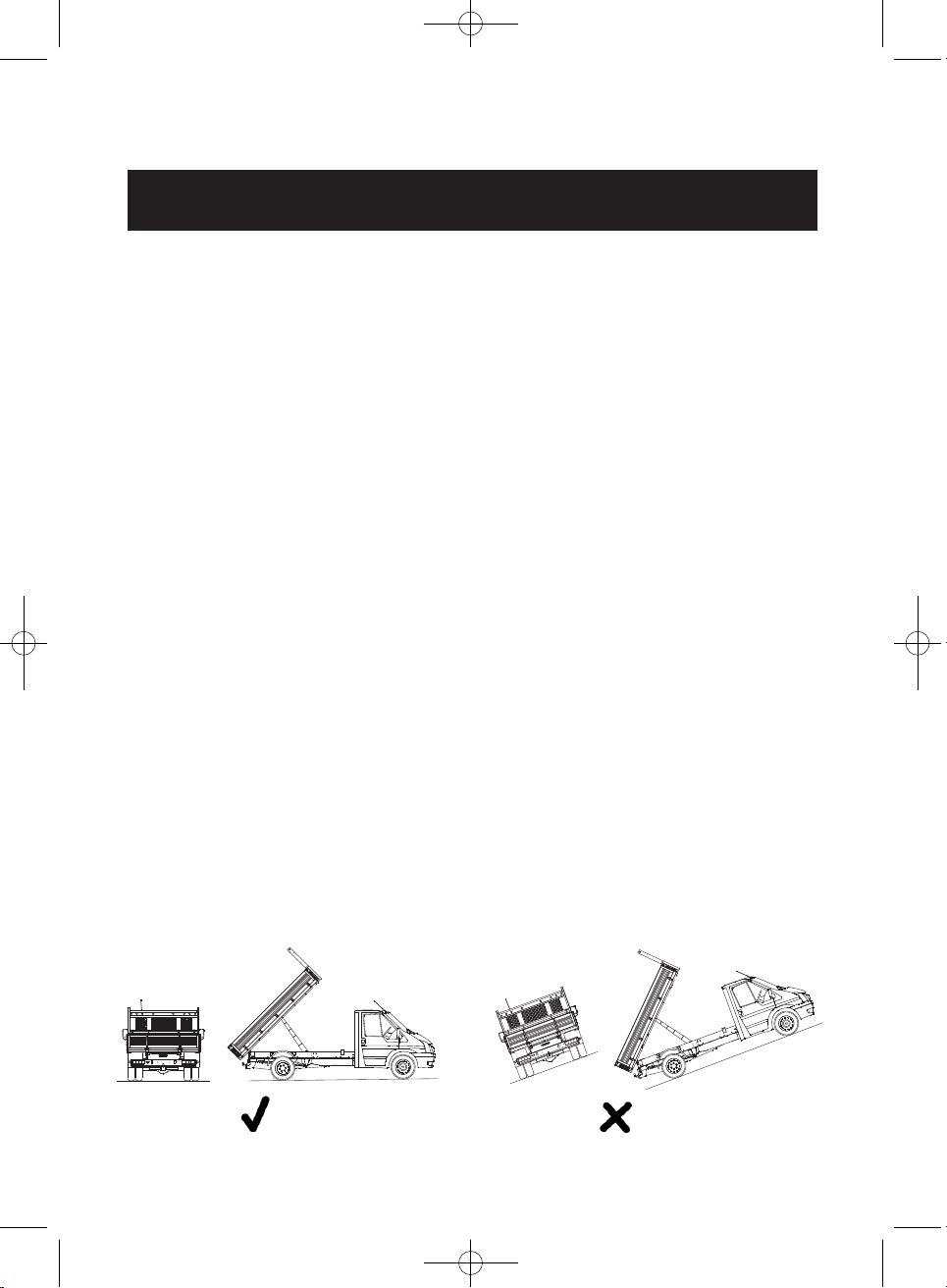
Preparation:
• Apply handbrake and switch on hazard warning lights.
• Ensure the ground bearing the weight of the vehicle is level and is firm.
• Check that the area surrounding the vehicle is free from personnel,
equipment and livestock, except for an assistant specifically tasked to guide
you to the area where the load is to be tipped. Health and Safety guidelines
on verbal or visual communication must be observed.
• Ensure the area surrounding the vehicle is suitably illuminated. (Night operation)
• Check overhead clearance for overhead cables and power lines, abort tip
or reposition vehicle if there are any overhead cables within the vicinity.
Operation:
To raise:
• Open the tailboard.
• Switch the Tipper Isolation Switch to the ‘ON’ position.
• Control the tip using the Tipper Control as described in the Tipper Controls
section of this manual.
• Lift the joystick to raise the body to the required height to either tip part or
the entire load. The body will automatically stop tipping when the ram is fully
extended. The tipping can be stopped at any time by releasing the joy stick.
A buzzer will sound when the joy stick is lifted.
To lower:
• Press the joystick downwards to lower the body. Keep depressed until the
warning sounder ceases.
• Close the tailboard ensuring that it is securely locked.
• Switch the Tipper Isolation Switch to the ‘OFF’ position.
1 Way Hand Book Nov'14:11-12 Seat Transit 28/11/14 11:13 Page 14
Tipper Controls
12
Dual Mode Tailboard: Tipthru/Tipover
A warning triangle or similar devices are permitted to be placed in the
road to warn of a temporary obstruction.
Ensure Tailboard is closed and locked before driving the vehicle.
Never drive the vehicle with the Tailboard in the lowered position.
Vehicle lighting must remain on during loading/unloading through the
hours of darkness or poor visibility.
Tailboard in lowered position obscures vehicle rear lights.
Avoid lowering the tailboard when stationary on the Public Highway.
Temporary obscuration during loading/unloading is permitted
providing other road users are warned of an obstruction in the road.
• Warning Triangle supplied with vehicle.
• Minimum four cones or pyramids.
• Minimum four flat traffic delineators.
• Road vehicle sign (large yellow sheet with a red triangle).
Description:
The tailboard is designed to operate in two different configurations dependant
upon the type of load, the configuration is determined by the operator prior to
tipping. The following guidelines are to enable the operator to identify and apply
the correct configuration before tipping.
Location:
The tailboard is mounted at the rear of the body, located by four latches/pivots.
Two positioned on the upper edge of the board, and two located on the lower
edge. The lower latch is remotely operated by a yellow handle mounted below
the tipper bed to the offside rear, behind the rear wheel fender.
Purpose:
• To safely discharge the payload from the rear aperture of the body.
• To provide restraint for fluid loads only. All loose loads must be restrained
using the load lashing rings provided. The tailboard is not designed to
prevent unrestrained loads from penetrating or bursting the tailboard.
CAUTION
WARNINGS
1 Way Hand Book Nov'14:11-12 Seat Transit 28/11/14 11:13 Page 15
Tipper Controls
13
TopHinged or TipThru:
Recommended for 'Fluid' loads:
•Sand
• Gravel
• Crushed concrete
• Type 1 aggregate
• Dry topsoil
• Wood shavings
BottomHinged or TipOver:
Recommended for loads consisting of
one or more large individual items:
• Logs
• Tree cuttings
• Clay
• White goods
• Furniture
If in doubt, always use the tipover mode.
Top Hinged / Tipthru mode:
If the load begins to jam or choke in the rear aperture created by the
tailboard hinging from the top, lower the body fully and clear the
obstruction. Do not continue to tip when a jam occurs.
Bottom Hinged / Tipover mode:
Always ensure that there is sufficient clearance for the tailboard to
hang without touching the ground, a minimum of 12" (300mm) is
recommended with the Tailboard in the lowered condition – body fully
laden and in the lowered position.
If a tow bar has been fitted, ensure that the tailboard has been fitted
with a protective guide (see Towing) to prevent it from jamming on the
tow hitch. If a guide is not installed the tailboard may be damaged.
WARNINGS
1 Way Hand Book Nov'14:11-12 Seat Transit 28/11/14 11:13 Page 16
14
Tipper Controls
Dual Mode Tailboard continued…
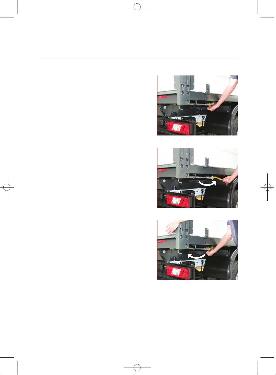
Use: TipThru mode:
To open tailboard:
• Locate the yellow remote operating
handle, pull outwards and forwards in
an arc until it stops.
To close tailboard:
• Brush down the lower edge and outer
vertical edges of the body to ensure
the tailboard can close without
jamming.
• Push the tailboard closed.
• Holding the tailboard closed with one
hand, return the remote release lever
to its shut position.
• Check the lower remote release
handle Is locked and the tailboard is
secure.
1 Way Hand Book Nov'14:11-12 Seat Transit 28/11/14 11:13 Page 17
 Loading...