


Table of contents
Introduction 2
Instrumentation 3
Controls and features 9
Charging 13
Starting 22
Driving 25
Roadside emergencies 31
Maintenance and care 45
Capacities and specifications 55
Accessories 57
Index 62
All rights reserved. Reproduction by any means, electronic or mechanical
including photocopying, recording or by any information storage and retrieval
system or translation in whole or part is not permitted without written
authorization from Ford Motor Company.
Copyrightr1999 Ford Motor Company
1

Introduction
WELCOME TO THE RANGER ELECTRIC VEHICLE
The 1999 Ranger Electric Vehicle is very similar to the gas-powered
Ranger in appearance, interior and controls. The Ranger Electric Vehicle
was built to be transparent from the gas-powered Ranger. There are
enough differences that you should read this manual. Operation is the
same, but some functions are different. The regular Ranger owner’s
manual covers common systems. This Owner’s Guide Supplement
contains the information specific to the Ranger Electric Vehicle.
ICONS
The warning icon. Read the following section on Warnings for a full
explanation.
WARNINGS
Provide information which may reduce the risk of personal injury or
prevent possible damage to others, your vehicle and its equipment.
INFORMATION ABOUT THIS GUIDE
The information found in this guide was in effect at the time of printing.
Ford may change the coctents without notice and without incurring
obligation.
2
Instrumentation
WARNING LIGHTS AND CHIMES
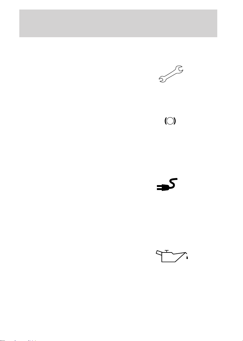
Service indicator lamp
The service indicator lamp indicates
that a vehicle malfunction has
occurred. The vehicle should be
returned to an authorized Ford
Electric Vehicle (EV) Dealer for service.
Brake warning lamp
The brake warning lamp illuminates
when there is a regenerative braking
system malfunction, low fluid level
in the master cylinder or low fluid
pressure in the hydraulic lines, or
when the parking brake is engaged. If the lamp remains illuminated after
the parking brake is fully released and the master cylinder is full, the
vehicle should be taken to an authorized Ford EV Dealer.
Charging lamp
The charging lamp illuminates when
the key is turned to the ON or
START position while the vehicle is
connected to the power control station (PCS). If the lamp flashes when
the key is in the ON position, there is a vehicle malfunction and the
drive battery cannot be charged. Confirm the vehicle is in park and the
PCS cord is properly attached. If the vehicle is in P (Park) and the PCS
cord is properly connected and the charging lamp continues to flash,
then the vehicle should be taken to an authorized Ford EV Dealer.
!
BRAKE
Low oil pressure lamp
The low oil pressure lamp indicates
that the transaxle oil lubrication
system is operating below the
desired pressure. Oil cannot be
added by the owner. The vehicle
should be returned to an authorized Ford EV Dealer as soon as possible.
Driving in excess of 50 miles to reach an authorized dealer may damage
the transaxle.
3
Instrumentation
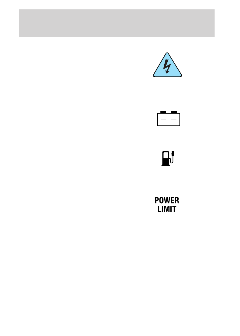
Electrical hazard warning lamp
The electrical hazard warning lamp
indicates a malfunction in the
high-voltage system. The vehicle will
not charge and must be returned to
an authorized Ford EV Dealer
immediately.
Auxiliary battery lamp
The auxiliary battery lamp indicates
there is an auxiliary battery
charging malfunction. Return the
vehicle to an authorized Ford EV
Dealer immediately.
Low fuel lamp
The low fuel lamp indicates that the
vehicle’s drive battery has reached a
10% state of charge. The vehicle
must be placed on charge. The
indicator will flash when the battery reaches a 0% state of charge.
Power limit lamp
The power limit lamp indicates a
system fault or reduced vehicle
performance to conserve remaining
drive battery power. As the vehicle
nears complete discharge, the power limit lamp will illuminate.
High-voltage accessories (A/C and heat) will be disabled. You will notice
a decrease in vehicle performance and you must return to a PCS (power
control station) immediately. The lamp will begin to flash and the
performance of the vehicle will be severely limited. The vehicle will
continue to operate until the drive battery is completely drained;
however, driving under this condition will damage the battery, resulting
in reduced battery life.
4

Instrumentation
Anti-lock brake system (ABS) lamp
The ABS lamp indicates that there
is a malfunction with the ABS. If the
light stays on or continues to flash
after the vehicle is started, return
the vehicle to an authorized Ford
EV Dealer for service.
Econ mode lamp
The econ mode lamp indicates that
the gearshift is in the E (Economy)
position. This mode is recommended
for urban traffic and will improve
range by increasing the effects of regenerative braking and limiting top
speed to 105 km/h (65 mph). The D (Drive) position is recommended for
highway operation at steady speeds.
Power reset lamp
The power reset lamp indicates that
the inertia shutoff switch has been
tripped and all high-voltage power
has been disconnected and power
has been limited to the traction battery. If there is no damage to the
vehicle, reset the switch to reactivate the high-voltage power systems.
ABS
5
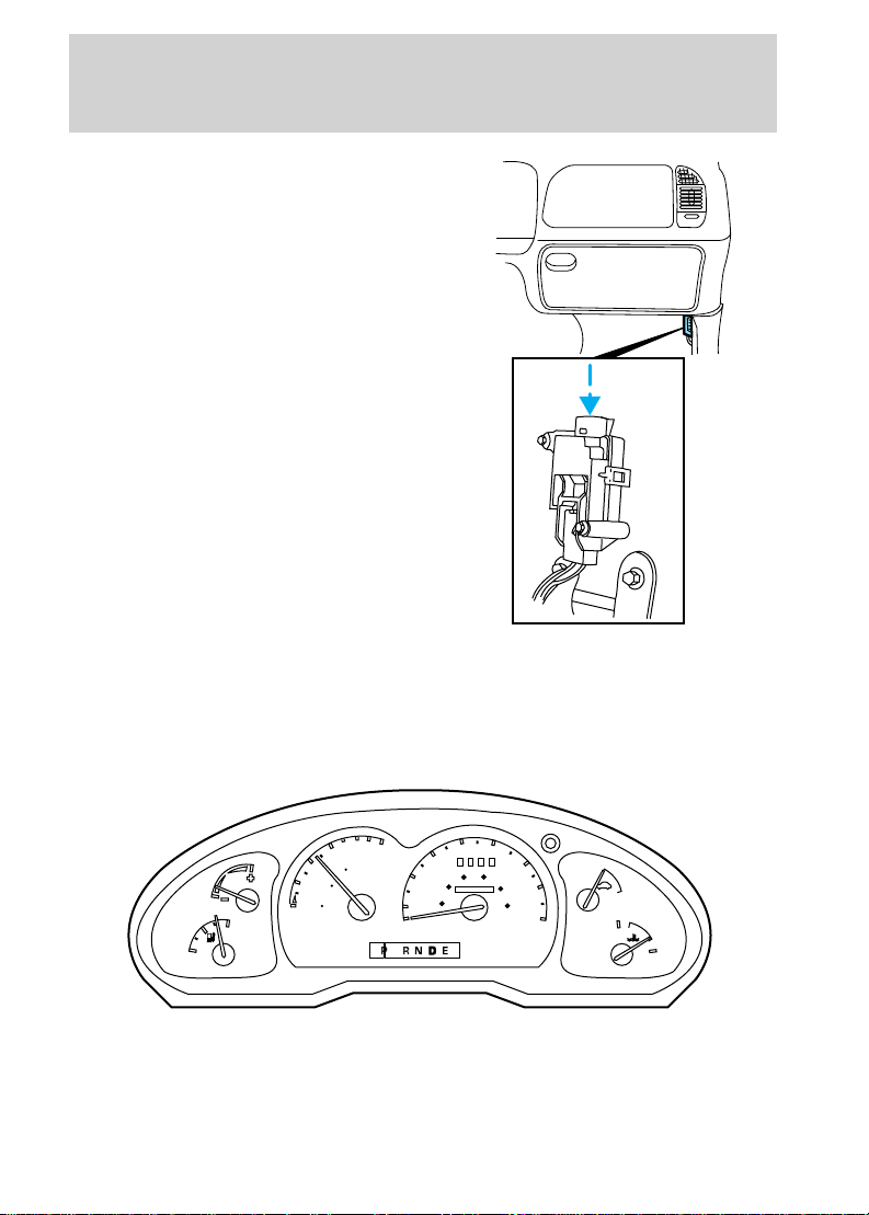
Instrumentation
The inertia shutoff switch is located
by the passenger kick panel. If there
is damage to the vehicle, have the
vehicle towed to an authorized Ford
EV Dealer.
RANGER EV FOR MEXICO AND CANADA
The instrument cluster on the Ranger EV for Mexico and Canada will be
equipped with metric gauges. All gauges operate as described below.
GAUGES
6
40
MPH
30
20
40
50
60 80
000000
60
100
70
120
km/h
ON
80
OFF
H
C
0
6
100
4
MILES
0
DISTANCE
50
TO EMPTY
0
2
km
0
0
20
10
ECON
F
E

Battery state of charge gauge
The battery state of charge gauge is
the equivalent of a fuel gauge on a
gasoline-powered vehicle. F (Full)
indicates that the battery is
completely charged. E (Empty)
indicates the battery has been
discharged to the point where
additional operation will damage
vehicle systems.
Economy gauge
The economy gauge provides
information about the vehicle’s
energy usage. Economical usage of
the vehicle is indicated by the gauge
reading near the plus (+) side and
will maximize the vehicle’s range.
Distance to empty gauge
The distance to empty gauge
estimates the remaining distance the
vehicle can travel before requiring a
drive battery recharge. The gauge
reading is based on remaining drive
battery energy, driving conditions
and recent vehicle usage.
Instrumentation
E
ECON
0
6
100
4
0
DISTANCE
50
TO EMPTY
km
0
MILES
0
2
0
F
7
Instrumentation
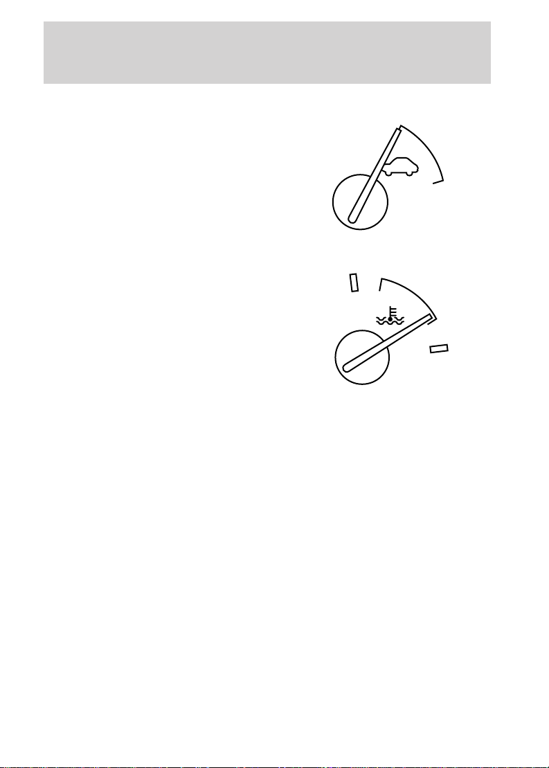
Motor enabled gauge
The motor enabled gauge indicates
that the vehicle is ready to drive.
Turning the ignition switch to the
full START position and releasing
will turn the vehicle on, and the
gauge will move to the ON position.
Temperature gauge
The temperature gauge indicates
the temperature of the vehicle’s
components. Unlike conventional
temperature gauges, it does not
start cold and move to normal. The
gauge sits at normal and moves to
hot or cold when there is a problem.
If the gauge moves to H (Hot),
vehicle performance will be limited
until the coolant temperature or drive battery temperature returns to
normal. The vehicle should be stopped and plugged into a PCS until it
has cooled down. The vehicle may need servicing. If the gauge moves to
C (Cold), the vehicle may have an extended charge time and a reduced
driving range.
ON
OFF
H
C
8
Controls and features
CLIMATE CONTROL SYSTEM
Your vehicle is equipped with an automatic temperature control (ATC)
system designed to maintain a selected temperature with a combination
A/C-Heater system.
Air conditioning (A/C) and heater controls
The control for your air conditioning and heater system is located at the
center of the instrument panel below the radio and will operate in the
KEY-ON position. Your air conditioner and heater will heat and/or cool
your vehicle interior depending on the function position and temperature
you select. The mode selector knob allows you to select heating or
cooling, and determine where the air will be directed. The temperature
control knob setting determines the desired interior temperature of the
vehicle. To turn your air conditioner or heater system on, select any
position except OFF. This will turn the fan on and allows air flow into
the vehicle. To turn your air conditioner or heater system off, select OFF.
This will turn the fan off and stop airflow from coming into the vehicle.
OFF
A/C
MAX
A/C
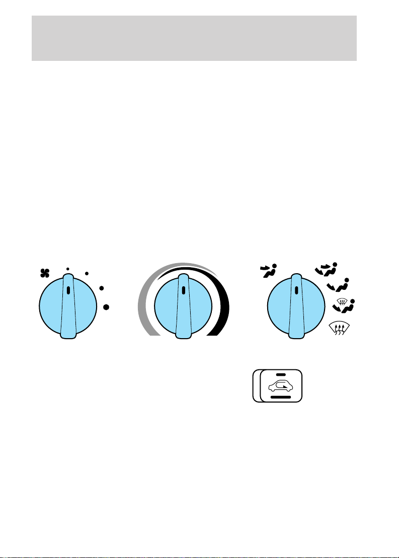
Recirculation switch
The recirculation switch is located
at the center of the instrument
panel just right of the radio. It
allows switching from outside air to
recirculated air in Panel,
Panel/Floor, and Floor modes. The recirculation switch operates for five
minutes, then shuts off. If more recirculation operation is desired, press
the control again. Note that in MAX A/C and A/C modes, the function is
automatic (stays in recirculation mode) and cannot be switched off. A
table of recirculation switch operation follows.
9
Controls and features
Recirculation Switch Operation
Icon Mode Recirculation
MAX A/C Max A/C Automatic
A/C A/C Automatic
OFF OFF Not Available
Floor/Defrost Not Available
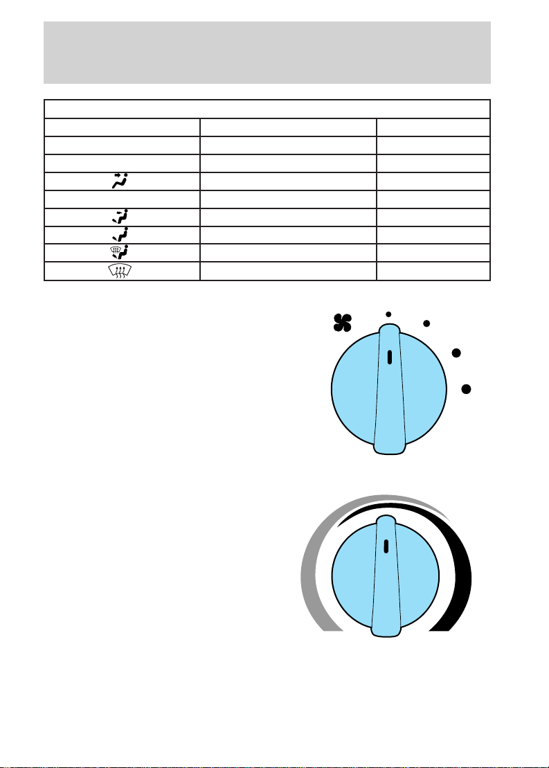
Fan speed knob
The left knob on the control is the
fan control knob, which controls the
volume of air flow. Rotate the knob
to the right to increase fan speed
and increase the amount of air
entering the vehicle. Four fan speed
positions are available and are
indicated by dots beside the control
knob. The largest dot is the
high-speed position.
Panel Selectable
Panel/Floor Selectable
Floor Selectable
Defrost Not Available
Temperature control knob
The temperature control knob is the
rotating knob located at the center
of the control with tapered red and
blue bands surrounding most of the
knob. The wide red part of the band
(full right) is the warm temperature
area. The wide blue part of the band
(full left) is the cool temperature
area. Any position selected between
full right and full left will give a
temperature between maximum
heating 29°C (84°F) and maximum cooling 18°C (64°F) (A/C and MAX
A/C modes only).
10
Controls and features
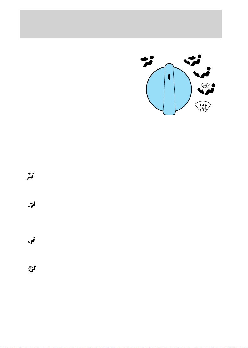
Mode selector knob
The right knob on the control is the
mode selector, which controls the
direction of the airflow inside the
vehicle.
• MAX A/C-Select to distribute recirculated air through the instrument
panel registers. This position produces cool air more rapidly to provide
faster cooling of your vehicle. Using MAX A/C may be noisier and less
economical than A/C.
• A/C-Select to distribute cool recirculated air through the instrument
panel registers. This position should be used for cooling except when
it is extremely hot or fast cooling of the vehicle is needed.
•
•
•
•
(panel)-Select to distribute outside air or recirculated air through
the instrument panel registers. The air may be heated based on
temperature selection. The air cannot be cooled below the outside
temperature regardless of the temperature setting.
(panel and floor)-Select to distribute outside air or recirculated
air through the instrument panel registers and to the floor ducts at
the same time. The air may be heated based on temperature selection.
The air cannot be cooled below the outside temperature regardless of
the temperature setting.
(floor)-Select to distribute outside air or recirculated air through
the floor ducts. The air may be heated based on temperature
selection. The air cannot be cooled below the outside temperature
regardless of the temperature setting.
(floor and defrost)-Select to distribute outside air through the
floor ducts and the windshield defroster ducts at the same time. If the
outside air temperature is 10°C (50°F) or warmer, the air conditioner
will dehumidify the air to prevent fogging. The air may be heated
and/or cooled based on temperature selection.
A/C
MAX
A/C
OFF
11

Controls and features
• (defrost)-Select to distribute outside air through the windshield
defroster ducts. Defrost can be used to clear ice or fog from the
windshield. If the outside air temperature is 10°C (50°F) or warmer
the air conditioner will dehumidify the air to prevent fogging. The air
may be heated and/or cooled based on temperature selection.
Operating tips
• In humid weather, select defrost before driving. This prevents your
windshield from fogging. After a few minutes of operation, you may
select another function.
• Remove any snow, ice or leaves from the air intake area of your heater
system that could block the air intake. The intake area is located at
the bottom of the windshield.
• If temperatures below -18°C (0°F), select recirculation before driving.
This will help warm the vehicle interior and minimize degraded
performance at low outside temperatures.
• The use of climate controls will reduce the vehicle’s range. Limit the
use of maximum heating and cooling of the vehicle interior.
12

Charging
CHARGING
Charging the Ford Ranger Electric Vehicle is a safe, simple process.
In-garage charging of the Ranger Electric Vehicle has received UL
approval. To maximize range, the vehicle should be connected to a
power control station (PCS) whenever possible to keep the battery fully
charged.
A conductive power control station (PCS) is required to recharge your
Ranger Electric Vehicle. The PCS consists of a “smart” box and a
connector and cable assembly that safely conducts AC power from the
utility supply grid to the vehicle inlet (located at the right front of the
vehicle, next to the right headlamp). An important feature of the PCS is
an integrated control pilot circuit, which performs safety functions such
as verifying the vehicle is present and safely connected, start/stop
control, confirming the smart box is ready to send power, confirming the
vehicle is ready to accept power, and continuously verifying the presence
of an equipment ground. The PCS supplies the power commanded by
the vehicle.
These stations will be in private locations (for example, residential or
fleet garages) or in public sites (for example, shopping malls,
restaurants, parking lots and so on). The PCS uses a 40 amp, 240 volt,
AC electrical supply.
The customer is responsible for ordering the PCS and getting it installed.
Your Ford Dealer will provide information on how to purchase and how
to get your PCS installed.
Consult your PCS owner’s manual for specific instruction on using your
PCS. Additional installations or service requirements that you might need
should be performed by a full service installer. Contact your Ford dealer
for a complete listing. If your installer finds any PCS malfunctions,
contact the PCS manufacturer.
Always follow charging instructions carefully. Failure to do so
may result in vehicle damage, personal injury or death.
To connect the PCS:
Always set the parking brake fully. Make sure the gearshift lever
is placed in P (Park) position. Turn off the “ignition” whenever
you leave your vehicle.
13

Charging
1. Park the Ranger Electric Vehicle. The vehicle’s charge inlet is at the
right front of the vehicle in the grille, next to the right headlamp.
2. Place the gearshift lever in P
(Park) and set the parking brake.
3. Turn the “ignition” to LOCK and remove the key from the “ignition.”
4. Open the charge inlet access door
in the front grille. The door is
hinged toward the right headlamp
and opens in the same manner as
the fuel filler door.
5. Pick up the PCS connector and
position it so that the release button
is facing upwards.
6. Align the PCS connector to the charge inlet, fully insert the connector
and make sure that the tabs on both sides of the connector engage the
slots in the inlet.
7. Gently push the connector down,
toward the bumper, until you hear a
click. The click means that the
connector is locked into the inlet.
14

Charging
8. The time required to charge the vehicle depends on the battery
temperature and the state of charge when the vehicle is plugged in. The
normal charge time is 6–8 hours. Reduced supply voltage, from the
recommended 240 volts, may adversely affect the normal charge time.
Estimated charge time
The amount of time required to fully charge the battery pack varies
depending upon the beginning state of charge and battery temperature.
Note that battery temperature is not necessarily the same as outside
temperature. The use of outside temperature to plan charge times,
however, is the most straightforward approach.
Typically it will take 6–8 hours for the vehicle to fully charge from
“empty” to “full.” Use the battery state of charge gauge as a guide to
assess whether enough charge time was allowed. If the gauge does not
indicate “full” when the “ignition” is moved to the ON position, one of
the following may have happened:
• The battery pack may be too warm or too cold. Charge times can
increase to 10 hours or more for warmer or cooler batteries. In sever
temperature conditions (battery temperature less than 5°C [41°F], or
greater than 60°C [140°F] for the lead-acid type and less than –25°C
[–13°F] or greater than 45°C [113°F] for the nickel metal hydride
type) the vehicle will not charge at all.
• The PCS may be malfunctioning.
• The battery pack may be out of electrical balance. The vehicle will
perform a balancing charge, which may take up to four hours for the
lead-acid type or two hours for the nickel metal hydride type over the
normal charging time, and then indicate “full.”
• The gearshift lever was not in P (Park).
• The battery pack (lead-acid type only) may be new. Vehicles that have
experienced less than 10 drive/charge cycles need an additional few
hours of charge time.
Refer to charging troubleshooting later in this section.
If none of the above apply, the vehicle should be returned to the PCS to
attempt to complete charging or taken to an authorized Ford EV Dealer.
Lead-acid traction battery
At 25°C (77°F), the drive battery can be charged to 80% capacity in
about three hours; 100% capacity requires approximately six to eight
15

Charging
hours. Completely charging the drive battery is important to ensure
maximum range and battery life. Ford recommended practice is that the
vehicle should always be left on-plug when not in use and be allowed to
fully charge before driving.
Charge time may increase at colder or hotter temperatures. The drive
battery must be above 5°C (41°F) and below 60°C (140°F) before
charging will begin. After being connected to a PCS, the vehicle will
automatically heat or cool the drive battery, as needed. When the battery
reaches the necessary temperature, charging will begin. Following a
complete charge in colder climates, charging will continue at periodic
intervals to maintain the battery at –10°C (14°F).
The Ranger Electric Vehicle should be connected to a PCS
whenever it is not being driven.
If a PCS is not available, the vehicle may be stored off-plug for up to 28
days without suffering permanent damage as long as the initial state of
charge is greater than 50%. The frequency of this type of storage should
be limited to a few occurrences over the life of the vehicle.
Nickel metal hydride traction battery
At 25°C (77°F), the drive battery can be charged to 80% capacity in
about five to six hours; 100% capacity requires approximately six to
eight hours. Completely charging the drive battery is important to ensure
maximum range and battery life. Ford recommended practice is that the
vehicle should always be left on-plug when not in use and be allowed to
fully charge before driving.
Charge time may increase at colder or hotter temperatures. The drive
battery must be above –25°C (–13°F) and below 45°C (113°F) before
charging will begin. After being connected to a PCS, the vehicle will
automatically cool the drive battery as needed. When the battery reaches
the necessary temperature, charging will begin. Following a complete
charge in colder climates, charging will continue at periodic intervals to
maintain the battery at –10°C (14°F).
The Ranger Electric Vehicle should be connected to a PCS
whenever it is not being driven.
If a PCS is not available, the vehicle may be stored off-plug for up to 28
days without suffering permanent damage as long as the initial state of
charge is greater than 50%. The frequency of this type of storage should
be limited to a few occurrences over the life of the vehicle.
16
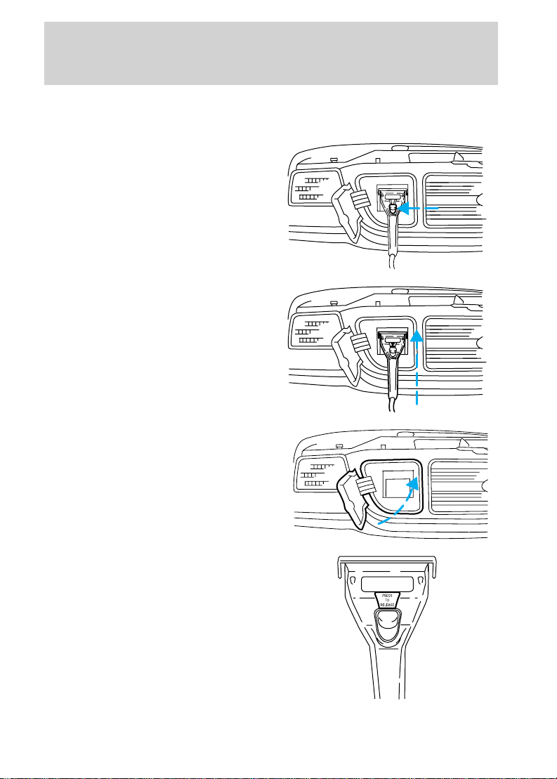
To disconnect the PCS:
1. Push the STOP button on the PCS.
2. Grasp the charge connector and
press the button in the center of the
handle.
3. Pull the charge connector upward
and pull it out of the inlet.
4. Close the charge inlet access door
in the front grille.
Charging
5. Return the connector and cable
to their proper location.
17

Charging
Charging troubleshooting using SCI systems (SCIT) equipment
If your vehicle fails to charge, follow this procedure to determine if your
Power Control Station (PCS) is operating properly:
1. Make note of any lights that are flashing or steadily illuminated on
your PCS.
2. Determine if the charge connector is properly inserted in the vehicle
inlet and locked in place.
3. Is the charge interrupt light illuminated? If yes, your vehicle may have
undergone a series of faults which forced the PCS to terminate the
charge process.
• Push the stop button.
• Unplug the connector from the vehicle inlet, to clear the fault.
• Inspect the cable and connector for any signs of possible damage (i.e.
cuts, tears or breaks in the cable insulation). If damage is found, stop
any further attempts to charge the vehicle and call the PCS
manufacturer for repair.
• If the cable and connector are undamaged reconnect the PCS to the
vehicle inlet. Is the charge interrupt light still illuminated or flashing?
Consult your authorized Ranger EV dealer to determine possible
vehicle fault.
4. Is the service light illuminated? If yes,
• Disconnect the charge connector vehicle inlet.
• Turn off the power to your PCS at the service or disconnect panel.
Turning off the power may allow the PCS to clear the fault.
• Turn the power back on and reconnect the PCS to the vehicle inlet. Is
the service light still illuminated? If so, call the PCS manufacturer for
repair or replacement. The toll free number is located on the PCS.
Charging troubleshooting using Electric Vehicle Infrastructure
(EVI
T
) equipment
If your vehicle fails to charge follow this procedure to determine if your
Power Control Station (PCS) is operating properly:
1. Make note of any lights that are illuminated or any messages being
issued by your PCS.
2. Determine if the charge connector is properly inserted in the vehicle
inlet and locked in place.
18

Charging
3. Is the protection light illuminated? If yes, your vehicle may have
undergone a series of faults which forced the PCS to terminate the
charge process.
• Push the stop button.
• Unplug the PCS charge connector from the vehicle inlet, to clear the
fault.
• Inspect the charge cable and connector for any signs of possible
damage (i.e. cuts, tears or breaks in the cable insulation). If damage is
found, stop any further attempts to charge the vehicle and call the
PCS manufacturer for repair.
• If the charge cable and connector are undamaged, reconnect the
vehicle. Is the charge interrupt light illuminated or flashing? Consult
your authorized Ranger EV dealer to determine possible fault.
4. Is the service light illuminated? If yes,
• Disconnect the PCS charge connector from the vehicle inlet.
• Turn off the power to your PCS at the service or disconnect panel.
Turning off the power may allow the PCS to clear the fault.
• Turn the power back on and reconnect the PCS to the vehicle. Is the
service light still illuminated? If so, call the PCS manufacturer for
repair or replacement.
• Are the ready or charging lights illuminated? If yes, your PCS is
operating correctly. Consult your authorized Ranger EV dealer to
determine vehicle fault.
• If turning the PCS power on and off or unplugging and plugging the
charge connector in the vehicle inlet does not cause any of the lights
to illuminate on the PCS, the PCS has either failed or has a damaged
charge cord. Call the PCS manufacturer for repair or replacement. The
toll free number is located on the PCS.
The Ranger Electric Vehicle should be connected to a PCS
whenever it is not being driven.
Battery pack heating/cooling system (lead-acid type)
The battery pack assembly contains 39 eight-volt batteries, wiring, a fan
for ventilation and cooling, a control system and optional heaters for cold
weather climates. These components work automatically when the
vehicle is on-plug charging, and are monitored by the battery pack
control system. Heating and cooling do NOT occur key OFF and off-plug.
19
 Loading...