

Follett 50FB425WL, 25FB425WL User Manual
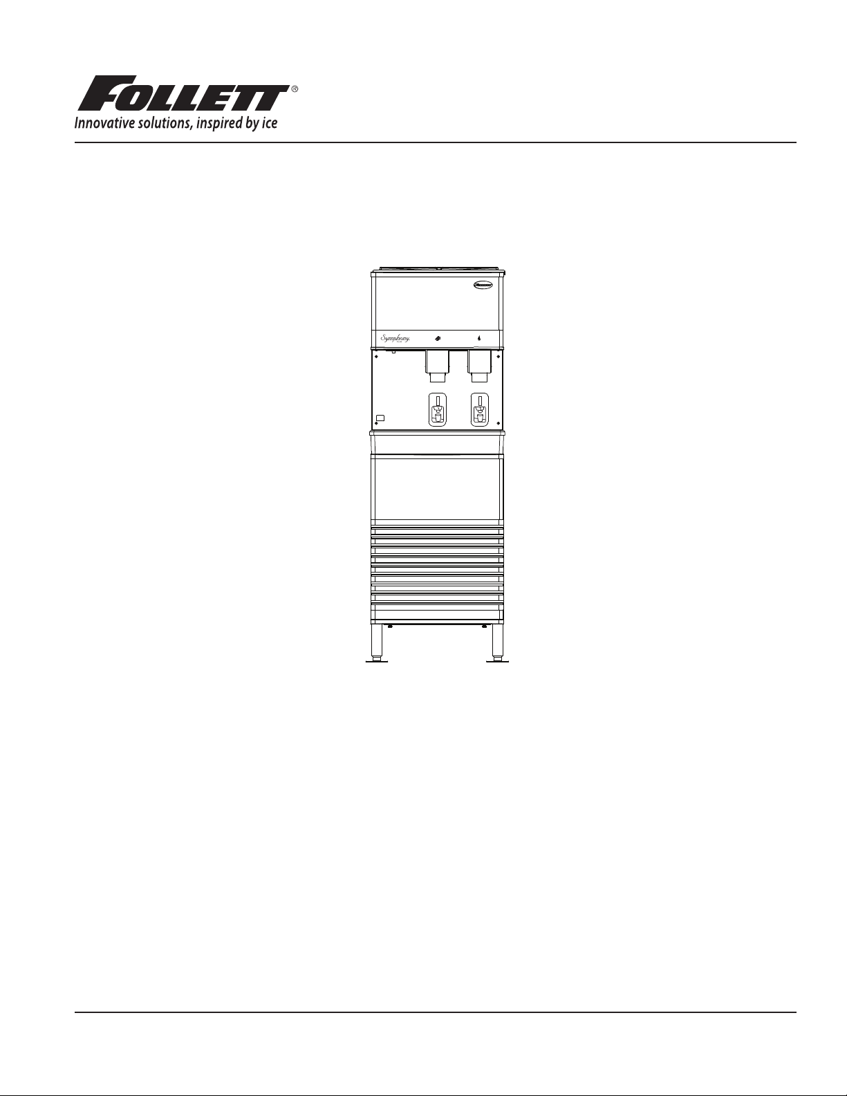
Symphony Plus™ 25 and 50 Series
Ice and Water Dispensers
25FB425A/W, 50FB425A/W
Operation and Service Manual
After serial number K39863
Please visit https://www.follettice.com/technicaldocuments
for the Operation and Service manual for your unit.
Welcome to Follett
Follett equipment enjoys a well-deserved reputation for excellent performance, long-term reliability and outstanding
after-the-sale support. To ensure that this equipment delivers that same degree of service, review this guide carefully
before you begin your installation.
Should you have need technical help, please call our Technical Service group at (877) 612-5086 or (610) 252-7301.
Please have your model number, serial number and complete and detailed explanation of the problem when
contacting Technical Service.
Getting Started
After uncrating and removing all packing material. Inspect the equipment for concealed shipping damage. All freight
is to be inspected upon delivery. If visible signs of damage exist, please refuse delivery or sign your delivery receipt
"damaged." Follett Customer Service must be notied within 48 hours. Wherever possible, please include detailed
photos of the damage with the original packaging so that we may start the freight claim process.
801 Church Lane • Easton, PA 18040, USA
Toll free (877) 612-5086 • +1 (610) 252-7301
www.follettice.com
Installation and Service Videos:
www.follettice.com/servicevideolibrary
01234616R01
Contents
Welcome to Follett. . . . . . . . . . . . . . . . . . . . . . . . . . . . . . . . . . . . . . . . . . . . . . . . . . . . . . . . . . . . . . . . . . . . . . . . . . . 3
Before you begin .......................................................................... 3
Specications .............................................................................. 4
Electrical ................................................................................ 4
Ambient ................................................................................. 4
Plumbing ................................................................................ 4
Ventilation clearances ...................................................................... 4
Approximate shipping weight ................................................................ 4
Installation ................................................................................. 5
Before you begin .......................................................................... 5
Installing freestanding dispensers ............................................................ 5
User information ............................................................................ 7
How the dispenser works ................................................................... 7
Cleaning and sanitizing ...................................................................... 7
Weekly ................................................................................. 8
Monthly ................................................................................. 8
Semi-Annually (more often if conditions dictate) ................................................. 8
Ice Machine and Dispenser ................................................................. 9
Dispenser troubleshooting .................................................................. 13
Lever model troubleshooting guide .......................................................... 13
SensorSAFE model troubleshooting guide .................................................... 14
Disassembly and replacement instructions ..................................................... 15
Ice transport tube replacement ............................................................. 16
Thermostat locations ..................................................................... 17
Replacement parts ......................................................................... 18
Dispenser exterior ........................................................................ 18
Dispense chute and splash panel (models with lever dispensing) .................................. 20
Dispense chute and splash panel (models with SensorSAFE infrared dispensing) ..................... 21
Dispenser electrical box – SensorSAFE models ................................................22
Dispenser electrical box – lever models ....................................................... 23
Hopper components ...................................................................... 24
Ice transport tubing ....................................................................... 25
Chilled water components ................................................................. 25
Water treatment accessories for Symphony Plus ice and water dispensers .......................... 26
2 25FB425A/W, 50FB425A/W
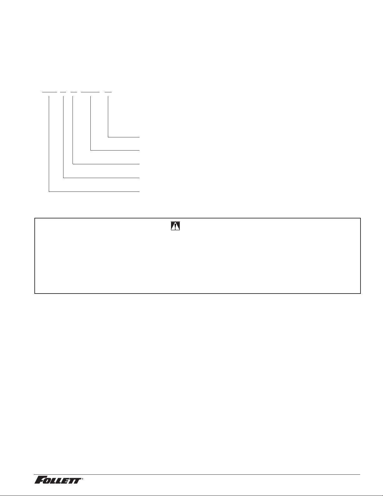
Check your paperwork to determine which model you have. Follett model numbers are designed to provide
information about the type and capacity of Follett ice dispensing equipment. Following is an explanation of the
different model numbers.
50FB425A
Condenser type, A = air-cooled
Ice machine capacity in lb per day
Ice machine location, B = ice machine in base of freestanding units
Dispenser conguration, F = freestanding
Approximate storage capacity in lb
CAUTION!
§ Do not tilt unit further than 30° off vertical during uncrating or installation.
§ Dispenser bin area contains mechanical, moving parts. Keep hands and arms clear of this area at all times. If
access to this area is required, power to unit must be disconnected rst.
§ Follett recommends a Follett water lter system be installed in the ice machine inlet water line (standard capacity
#00130299, high capacity #00978957, carbonless high capacity #01050442).
§ Prior to operation clean the dispenser in accordance with instructions found in this manual.
§ Ice is slippery. Be sure counters and oors around dispenser are clean, dry and free of ice.
25FB425A/W, 50FB425A/W 3
Specications
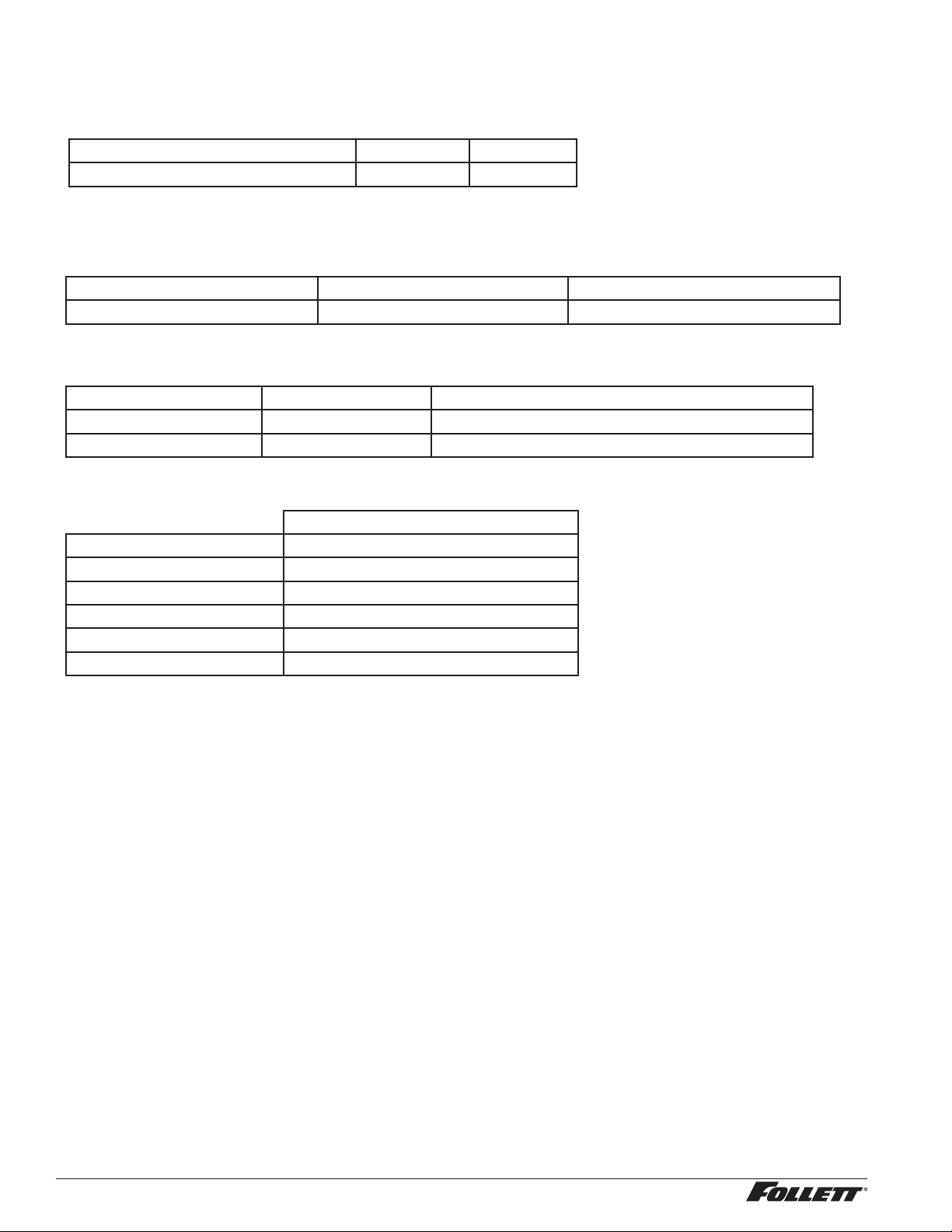
Electrical
§ Freestanding models (25FB425A/W, 50FB425A/W) require a dedicated circuit.
Total system Max. fuse
Basic electrical: 115 V/60 Hz/1 phase 11.0A 15A
§ Dispensers and RIDE ice machines are supplied with 7-foot power cord with NEMA 5-15 hospital-grade plug.
Connect to a dedicated 15A dedicated circuit.
Note: It is preferred that circuit be protected by a GFCI.
Model Electrical connection Circuits required
25FB425A/W, 50FB425A/W cord & plug provided 115/60/1, 20A max. fuse size
Ambient
Air temp 100 F/38 C Max. 50 F/10 C Min. (Best performance below 80 F/27 C)
Water temp 90 F/32 C Max. 45 F/7.2 C Min. (Best performance below 70 F/21 C)
Water pressure (psi/bar) 70/5 Max. 10/0.7 Min.
Plumbing
25/50 FB with ice machine in base
Dispenser drain 3/4" MPT
Ice machine drain 3/4" MPT
Dispenser water inlet 3/8" FPT
RIDE IM water inlet –
Cond. inlet – w/c only 3/8" FPT
Cond. drain – w/c only 3/8" FPT
Note: Water shut-off recommended within 10 ft. (3 m) of dispenser. Drain to be hard-piped and insulated. Maintain
at least 1/4" per foot (20 mm per 1 m) run of slope.
Ventilation clearances
§ 4" (10.2 cm) required at rear for freestanding models (25FB425A/W, 50FB425A/W).
Note: 12" (30.5 cm) at top advised for service.
Dry weight
§ 25/50 FB 212 lb (96 kg)
4 25FB425A/W, 50FB425A/W

Installation
Before you begin
§ All dispensers must be installed level in both directions to ensure proper operation.
§ SensorSAFE™ dispensers are shipped with a plastic, protective lm on sensor lenses. For proper operation,
plastic lm must be removed after installation.
Installing freestanding dispensers
1. Position dispenser in desired location and adjust legs to level in both directions.
2. Connect water supply to 3/8" FPT tting on back of dispenser (Fig. 1).
3. Connect separate drain lines to 3/4" MPT dispenser drain tting, and 3/4" MPT ice machine drain tting
on back of dispenser.
4. Run drain lines to wall or oor drain. If ice machine drain tting is below an intended wall drain, a
condensate pump must be used.
5. If ice machine is a water-cooled unit, connect water-cooled condenser supply line to 3/8" FPT condenser
inlet tting on back of dispenser.
Note: Do not run condenser supply water through ice machine water lter system.
6. Connect condenser drain line to 3/8" FPT condenser outlet tting on back of dispenser.
Important: Do not connect condenser drain line to any other drain lines.
7. Plug dispenser into 15A rated NEMA 5-15 wall socket.
8. Remove front cover of base section by removing two screws at bottom corners of cover. Allow cover to
drop approximately 3/8" (5 mm) and pull forward.
9. Turn on water supply and check for leaks.
25FB425A/W, 50FB425A/W 5
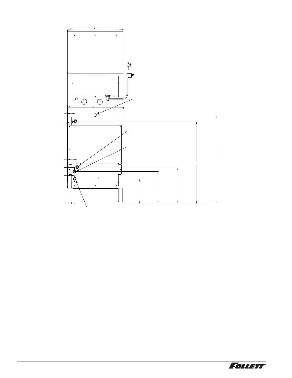
Fig. 1 – Rear connections, freestanding models
access panel
10.62" (27 cm)
2.9" (7.6 cm)
3/8" FPT
water inlet
3.75" (9.5 cm)
2.775" (6.9 cm)
2.81" (7.2 cm)
power cord
3/4" MPT drain
3/8" FPT condenser outlet location
(water-cooled only)
3/8" FPT condenser outlet location
(water-cooled only)
31.5" (80 cm)
14" (35.7 cm)
33.75" (85.8 cm)
12.38" (31.4 cm)
9.62" (24.4 cm)
3/4" MPT icemaker drain location
10. Remove top front cover by removing two screws at bottom corners of cover. Lift cover slightly and pull
forward.
11. If dispenser is equipped with SensorSAFE remove protective plastic coating from dispense sensor labels.
12. Turn on dispenser power and bin signal rocker switches. Check dispenser and ice machine operation.
13. Clean ice machine according to cleaning section. Discard ice made during cleaning process.
14. Turn off ice machine bin signal switch.
15. Remove dispenser hopper lid; clean dispenser according to instructions in Cleaning section.
16. Turn ice machine bin signal switch on and replace front covers, securing with screws.
6 25FB425A/W, 50FB425A/W
User information
How the dispenser works
Follett’s 25/50 series automatic-load ice and water dispensers are equipped with Follett’s 425 lb (181kg)/day
ice machine. In the continuous icemaking process, water freezes to the inside wall of the evaporator. A rotating
stainless steel auger carries the ice to the top of the evaporator where it is compressed and extruded through an
outlet port. The ice is then pushed through a tube to the storage hopper. When the hopper is full, a bin thermostat
opens and shuts the ice machine off. When the dispense mechanism is activated, a dispense motor is turned on,
causing the wheel to turn. This moves ice to the dispense chute where it drops by gravity into the container held
below the chute.
How SensorSAFE infrared dispensing works
Follett’s SensorSAFE infrared dispensing maximizes sanitation and minimizes the possibility of cross-contamination
by eliminating physical contact between the cup or container and dispenser. Sensors in the panel use reected
infrared light to detect the presence of the container and send a signal to a control board which then activates the
appropriate components for ice or water dispensing.
The SensorSAFE infrared dispensing package includes a cleaning switch under the left side of the front cover
which temporarily shuts off dispensing to allow cleaning of the panel and lenses. If the switch is not turned back on
after cleaning, the dispenser automatically resets after two minutes for normal operation.
SensorSAFE infrared dispensing also includes a time limit safety feature which automatically stops ice dispensing
after one minute of continuous dispensing. Dispensing can be resumed by moving the container away from the
dispenser and returning it to the activation zone.
Cleaning and sanitizing
Follett ice machines and dispensers, and their associated cleaning and sanitizing procedures, are designed for
use with potable water sources. The presence, or suspected presence, of infectious agents may call for additional
measures, including the replacement of components and more comprehensive disinfection measures. Follett
recommends that these cleaning and sanitizing procedures be reviewed with the appropriate infectious agent
subject matter experts to assure complete remediation.
Periodic cleaning of Follett’s ice and water dispenser and ice machine system is required to ensure peak
performance and delivery of clean, sanitary ice. The recommended cleaning procedures that follow should be
performed at least as frequently as recommended and more often if environmental conditions dictate.
Follett recommends sanitizing the pressurized water lines prior to cleaning the ice machine/dispenser. Follett
offers two kits: order P/N 01089572 when a Follett lter system with a pre-lter bowl is present, or P/N 01089580
when a Follett lter system is not present. Follow the instructions provided with the respective kits to sanitize the
pressurized water lines immediately before cleaning the ice machine/dispenser.
Cleaning of the condenser can usually be performed by facility personnel. Cleaning of the ice machine system
should be performed by your facility’s trained maintenance staff or a Follett authorized service agent. Regardless
of who performs the cleaning, it is the operator’s responsibility to see that this cleaning is performed according to
the schedule below. Service problems resulting from lack of preventive maintenance will not be covered under the
Follett warranty.
Recommended cleaning intervals*
Symphony Plus Frequency
Drain Line weekly
Drain Pan/Drip Pan weekly
Exterior, Water Station Tube as needed
Condenser monthly (air-cooled only)
Dispenser and Components semi-annually
Ice Machine semi-annually
Transport Tube semi-annually
Ice Storage Area/Bin semi-annually
Pressurized Water Sanitizing semi-annually
* Ice machine and dispenser must be cleaned prior to start-up.
25FB425A/W, 50FB425A/W 7
Weekly
CAUTION!
§ Do not use solvents, abrasive cleaners, metal scrapers or sharp objects to clean any part of the dispenser.
Dispenser drain pan and drain line
§ Pour 1 gal. (3.8 L) of hot tap water into drain pan to ush drains.
Splash panel front, SensorSAFE infrared dispensing
1. Deactivate dispensing by pressing and releasing clean switch located on left side of unit under top front
cover.
2. Clean lens and splash panel front using a soft cloth and mild, non-abrasive, non-chlorine based cleaner.
3. Reactivate dispensing by pressing and releasing clean switch again.
Monthly
CAUTION!
§ Do not use solvents, abrasive cleaners, metal scrapers or sharp objects to clean any part of the dispenser.
Condenser (air-cooled ice machine only)
§ Use a vacuum cleaner or stiff brush to carefully clean condenser coils of lint and debris to ensure optimal
performance.
Semi-Annually (more often if conditions dictate)
§ A cleaning procedure should always include both the ice machine and dispenser; ice machine should be cleaned
rst, followed by the dispenser.
§ Icemaking system can be cleaned in place.
CAUTION!
§ Wear rubber gloves and safety goggles (or face shield) when handling SafeCLEAN Plus™ and IMS-III solutions.
§ Use only Follett approved cleaners.
®
§ It is a violation of Federal law to use the Nu-Calgon
§ Do not use solvents, abrasive cleaners, metal scrapers or sharp objects to clean any part of the dispenser.
Cleaning & Sanitizing Tool Checklist
§ (1 or 2) 1.5 Gallon (or larger) plastic bucket
§ (2) clean cloths
§ Sanitary gloves
§ Safety glasses
§ (2) SaniSponge™ (P/N 00131524 - single sponge)
§ SafeCLEAN Plus ice machine cleaner
§ [OPTIONAL] Nu-Calgon IMS-III no-rinse sanitizer (P/N 00979674 – 16 oz. bottle)
SafeCLEAN Plus Solution: Follow the directions on the Follett Follett SafeCLEAN Plus packaging to mix 1 gal.
(3.8 L) of
cleaning
[OPTIONAL] No-rinse Sanitizing Solution: Follow the directions on the
mix 1 gal. (3.8 L) of
IMS-III solution in a manner inconsistent with its labeling.
solution. Use 100 F (38 C) water.
Nu-Calgon IMS-III
IMS-III
solution. Use 100 F (38 C) water.
Plus packaging to
8 25FB425A/W, 50FB425A/W

Ice Machine and Dispenser
Cleaning Procedure
Note: Check drains and drain cup to ensure they are open and owing freely.
1. If ice machine was running recently, ensure that the evaporator is completely free of ice before
proceeding. If there is ice in the evaporator, complete steps 2-7 using only hot water to remove the ice,
then begin Cleaning/Descaling Procedure again.
2. Remove front cover of the dispenser and turn OFF bin signal switch.
3. Dispense all ice from storage hopper and discard.
4. Remove the cover of the base stand.
5. Press CLEAN switch. The MAINTENANCE light will turn on and the machine will drain. Wait for the LOW
WATER light to turn on.
6. Remove lid from cleaning cup and ll (about 1 quart) until SafeCLEAN Plus solution completely lls the
reservoir. Place lid back on cup. Save remainder of SafeCLEAN Plus solution.
7. CLEANER FULL light will turn on and machine will start cleaning cycle, then rinse three times; this
process takes approximately 15 minutes.
8. While ice machine is cleaning/descaling, clean dispenser as follows:
a. Turn OFF dispenser power.
b. Remove hopper lid.
c. Remove knurled nuts from front of storage hopper.
d. Remove stud assembly, baffle, wheel, and any remaining ice.
e. Remove dispense chutes from splash panel.
f. Submerse drain grille in SafeCLEAN Plus solution and allow to soak to remove any scale buildup.
g. Wipe inside of hopper lid, stud assembly, baffle, wheel, inside of storage area, dispense chutes, drain grille
and drain pan with damp cloth wrung out in SafeCLEAN Plus solution. Thoroughly rinse all parts with damp
cloth wrung out with clean water.
Note: To avoid possible damage to motor assembly, only use a damp cloth to clean storage hopper. Do
not allow water to run through motor shaft hole in bottom of hopper.
9. When machine is nished cleaning, the MAINTENANCE light will turn off.
Finish cleaning – SafeCLEAN Plus only
10. If the dispenser is equipped with a Chilled Water Accessory continue to Step 10.a; if not, skip to Step11.
a. Remove four screws securing splash panel.
b. Disconnect 3/4" (19 mm) drain line from bottom of chilled water canister.
c. Loosen (do not remove) screw securing front bracket of chilled water canister to bottom of dispenser hopper.
d. Rotate canister clockwise to release front bracket, then pull canister forward to disengage rear bracket.
e. Remove chilled water coil from canister and clean with cloth wrung out in
f. Wipe inside of chilled water canister with cloth wrung out in
g. Rinse all above items with damp cloth wrung out in clear water.
h. Reinstall chilled water coil into canister (rubber alignment grommet on coil tubing must be located outside
chilled water canister to hold coil securely against canister wall).
i. Reinstall chilled water assembly on dispenser and tighten screw securing front bracket.
j. Reconnect 3/4" (19 mm) drain line to chilled water canister.
11. Reinstall dispense chutes, wheel, baffle, stud assembly and knurled nuts.
12. Remove top bearing insulation, loosen Phillips-head screw on nozzle connected to evaporator. Remove
nozzle from evaporator side only, leave other side of nozzle connected to transport tube.
13. Soak one SaniSponge in remaining SafeCLEAN Plus solution.
14. Insert the sponge soaked in cleaning solution into nozzle, then insert a dry sponge into the nozzle.
15. Replace nozzle onto evaporator and tighten screw. Ensure drain is connected to reservoir and vent tubes
are connected to evaporator drain pan. Replace top bearing insulation.
16. Turn ON bin signal switch. Wait for ice to push sponges through transport tube.
SafeCLEAN Plus
SafeCLEAN Plus
solution.
solution.
25FB425A/W, 50FB425A/W 9
 Loading...