

Page 1
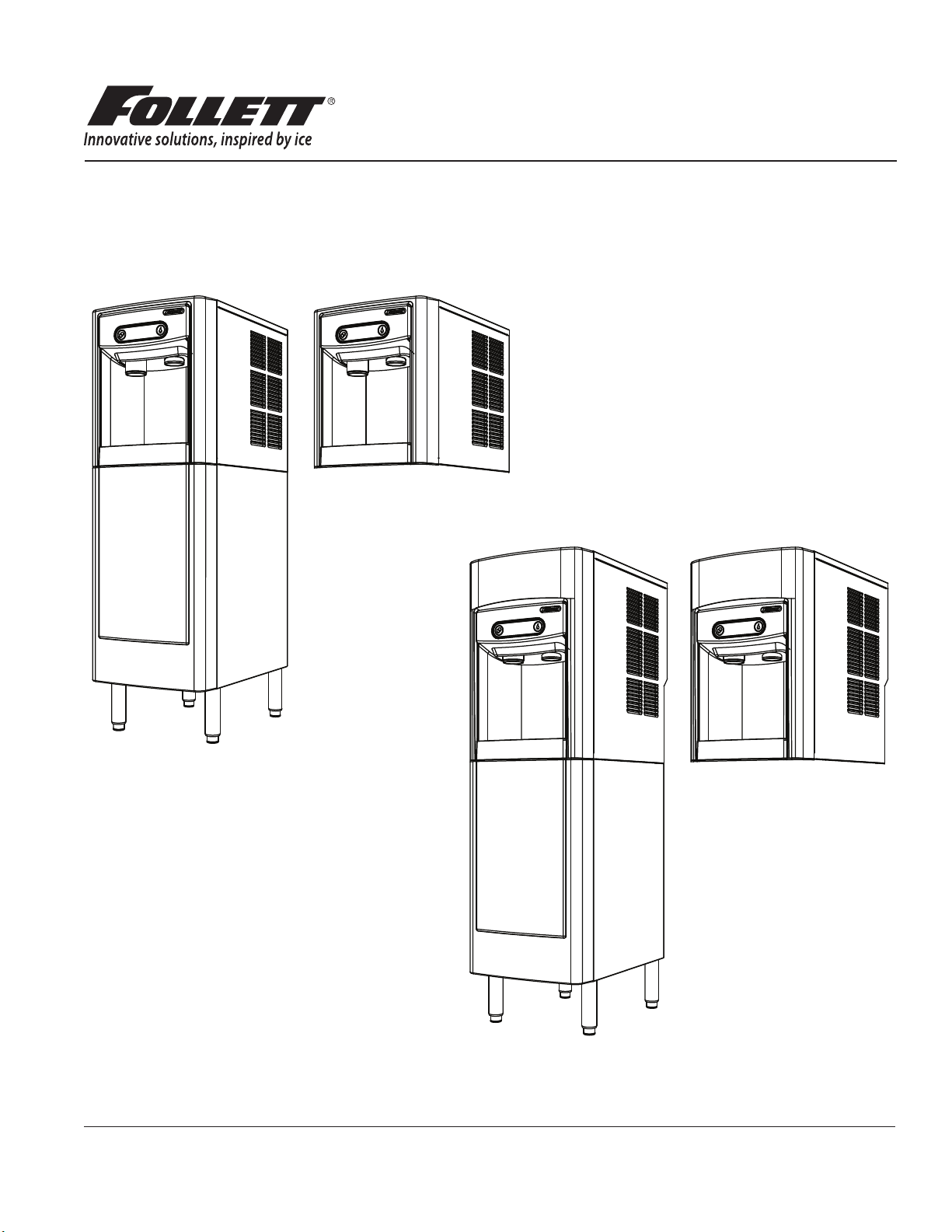
Ice and Sparkling Water Dispenser
with Chewblet® Ice Icemaker
7CI100A, 7FS100A, 15CI100A, 15FS100A
Installation, Operation and Service Manual
7FS100A
7CI100A
15FS100A
15CI100A
Following installation, please forward this manual
to the appropriate operations person.
801 Church Lane • Easton, PA 18040, USA
Toll free (877) 612-5086 • +1 (610) 252-7301
www.follettice.com
Order parts online:
www.follettice.com
01156496R01
Page 2

Follett 7/15 Series Sparkling - Installation Checklist
Before beginning:
Separate boxes for dispenser, carbonator, installation kit, and accessories.
Customer-supplied, beverage-grade CO2 cylinder is present and full.
Assemble system:
Sparkling Water, Still Water, and power cord installed between carbonator and
dispenser.
Water Block ood protection device set to “2” and installed vertically after tee on the
water line to the carbonator water inlet.
ShockBlok water pressure regulator installed after Water Block and before
carbonator water inlet.
CO2 regulator set to 60 psi.
Turn on water, plug in dispenser – leave carbonator and CO2 off:
No leaks in plumbing connections. Check before reinstalling dispenser side panel.
Carbonator air is bled according to installation instructions.
Turn on carbonator and CO2:
Sparkling and Still Water ow from correct button press.
Carbonator pump cycles on and off between Sparkling Water dispenses.
Perform 4 separate 16 oz. Sparkling Water dispenses.
Notes: Allow carbonator pump to cycle off between dispenses.
Do not exceed 32 oz. continuous sparkling dispense.
Allow at least 1 hour for chiller to reach optimal temperature.
2 Sparkling Ice and Water Dispenser 7CI100A/7FS100A, 15CI100A/15FS100A
Page 3
Contents
About Follett Sparkling Water .................................................................... 4
Welcome ...................................................................................... 4
Before You Begin ............................................................................... 5
Important Safety Information ..................................................................... 6
Specications ................................................................................. 6
Dispenser Dimensions ........................................................................ 6
Carbonator Dimensions ....................................................................... 6
Ambient Information .......................................................................... 6
Plumbing ................................................................................... 6
Specications ................................................................................. 7
Water ..................................................................................... 7
Clearances ................................................................................. 7
Electrical ................................................................................... 7
Refrigeration ................................................................................ 7
Heat Rejection .............................................................................. 7
Chiller/Carbonator Detailed Drawing ............................................................. 7
7 Series Detailed Drawing ..................................................................... 8
15 Series Detailed Drawing .................................................................... 9
Installation ....................................................................................10
Countertop Installation ........................................................................10
Freestanding Installation ...................................................................... 12
Final Connections - Countertop Installation ...................................................... 14
Final Connections - Freestanding Installation ..................................................... 16
Maintenance/Cleaning Mode .................................................................... 19
Accessing Internal Components ................................................................. 19
DIP-switch Settings ............................................................................ 20
NSF-approved Cleaning and Sanitizing Procedure .................................................. 21
User Interface and Exterior Cabinet Cleaning ...................................................... 22
Flow Straightener Cleaning/Sanitizing ............................................................ 22
Chiller/Carbonator Sanitizing Instructions ......................................................... 22
Service ...................................................................................... 23
LED Indicator Description ..................................................................... 23
Evaporator Disassembly ...................................................................... 24
Evaporator Assembly ........................................................................ 27
Condenser Fan Motor Removal (7 Series Shown) ................................................. 31
Bin Melt Water/Evaporator Feed/Clean Out System Schematic ....................................... 32
Vent System Schematic ...................................................................... 32
Refrigeration Schematic - Dispenser ............................................................ 33
Water Feed Schematic ....................................................................... 34
Chiller/Carbonator ........................................................................... 35
User Interface Display Identication ............................................................. 36
Electrical Wiring Diagram - Dispenser ........................................................... 38
Electrical Wiring Diagram - Chiller/Carbonator ..................................................... 39
Parts ........................................................................................ 40
7 Series Exterior ............................................................................ 40
7 Series Interior ............................................................................ 42
15 Series Exterior ........................................................................... 44
15 Series Interior ........................................................................... 46
7 Series Bin Assembly ....................................................................... 48
15 Series Bin Assembly ...................................................................... 50
Evaporator Assembly ........................................................................ 52
Base Stand ................................................................................ 54
Chiller/Carbonator ........................................................................... 55
Sparkling Ice and Water Dispenser 7CI100A/7FS100A, 15CI100A/15FS100A 3
Page 4

About Follett Sparkling Water ––––––––––––––––––––––––––––––––––––––––
Follett’s 7 and 15 Series Ice and Sparkling Water dispensers produce Follett’s consumer-preferred Chewblet®
nugget ice as well as chilled and sparkling water. Follett’s premium sparkling drinking water is characterized by
small, dense bubbles. Follett does not produce the large “popping” bubbles found in sugary soda drinks. A good
comparison for Follett’s sparkling water would be Perrier or Pellegrino. It is important to note this distinction.
Customers who are seeking the big-bubbles found in club soda or soft drinks may be disappointed. However, taste
tests conducted by Follett at a variety of test sites have veried a high level of approval for Follett’s sparkling water.
Two factors play a large part in producing quality sparkling water. First, the water being injected with food grade
CO2 must be controlled between 46 F – 51 F. Second, the incoming water must have the proper range of mineral
content. Too many minerals can lead to premature scaling of the ice maker and the need for excess product
maintenance. Too few minerals can result in avorless sparkling water which can go at quickly. To ensure the
highest quality sparkling water, the water supply (after ltration) must have a hardness between 80 ppm and
400ppm TDS. Test your water rst and lter as necessary to achieve the appropriate hardness. Filtration should
also remove any chlorine tastes from the water, another enemy of good sparkling water taste.
An appropriate source of CO2 must be in place prior to installation of this ice and water dispenser. It is critical that
the Follett sparkling system be fed only food grade CO2. Follett does not sell or distribute CO2. Follett provides
a regulator for standard UN1013 beverage grade CO2 tanks with a CGA-320 thread. The CO2 tanks and CO2
itself must be sourced locally by the end user. Tanks must be secured at all times to prevent from tipping, and
must be stored below 120°F. There are a variety of local codes and restrictions about the handling and storage of
CO2 across the U.S. Please consult a local CO2 distributor for more information. Follett can provide some limited
guidance to help nd an appropriate source for CO2, however, Follett does not guarantee the ability to provide a
CO2 contact in every market.
Welcome ––––––––––––––––––––––––––––––––––––––––––––––––––––––––––
Follett equipment enjoys a well-deserved reputation for excellent performance, long-term reliability, and outstanding
after-the-sale support. To ensure that this product delivers that same degree of service, we ask that you take a
moment to review this manual before beginning the installation. Should you have any questions or require technical
help at any point, please call our technical service group at (877) 612-5086 or +1 (610) 252-7301.
4 Sparkling Ice and Water Dispenser 7CI100A/7FS100A, 15CI100A/15FS100A
Page 5
Before You Begin –––––––––––––––––––––––––––––––––––––––––––––––––––
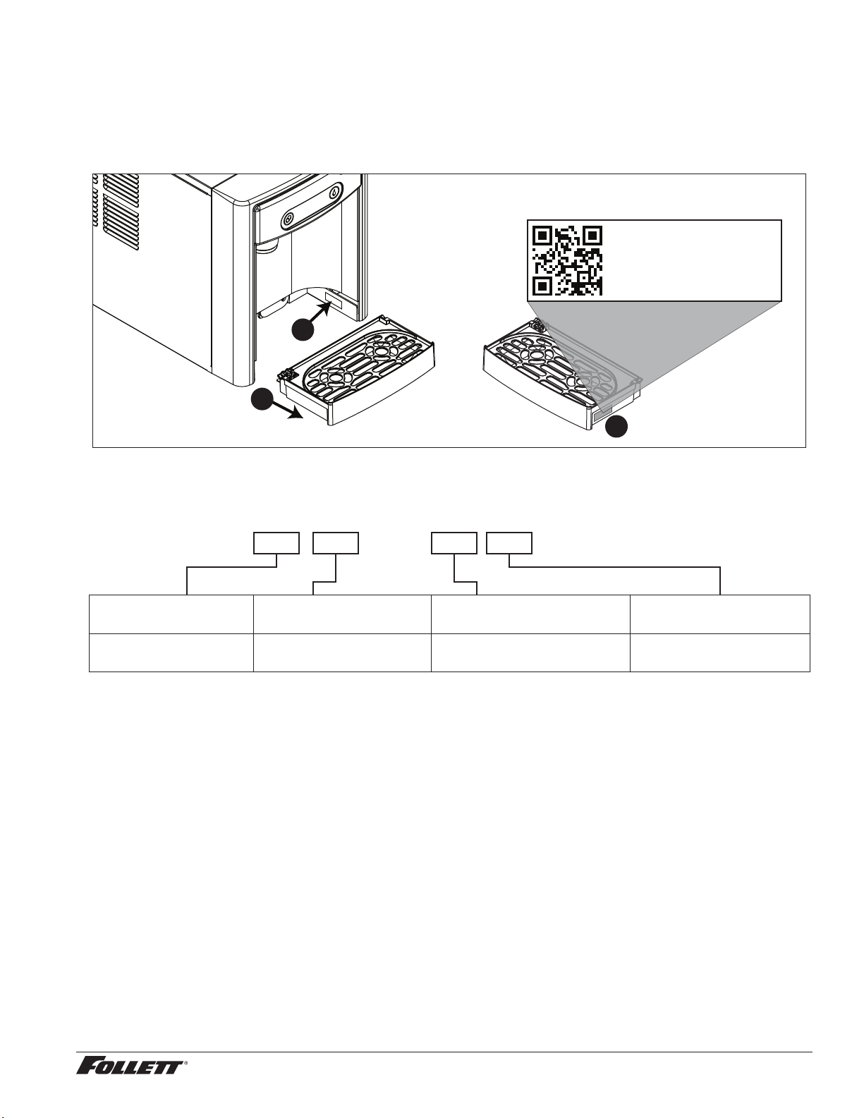
After uncrating and removing all packing material, inspect the equipment for concealed shipping damage. If damage
is found, immediately notify the shipper and contact Follett Corporation so that we can help in the ling of a claim,
if necessary. If needed, the serial number of your dispenser can be found by removing the drip tray ❶ and locating
the serial number label ❷. A QR Code is located on the right hand side of the drip tray ❸. This code allows you to
access manuals, technical bulletins, and on-line training related to the 7 Series and 15 Series dispensers.
Scan to access technical
documentation or visit
www.follettice.com/7and15seriesdocs
00981100R01
2
1
3
Check your paperwork to verify that you received the correct dispenser. Follett conguration numbers are designed
to provide information about the type of dispenser you are receiving. The following is an explanation of the different
model numbers.
7 CI 100 A
Dispenser Storage
Capacity
7 lb (3.1 kg)
15 lb (6.8 kg)
Conguration Icemaker Capacity Condenser
CI Countertop
FS Freestanding
100 lbs (45.3 kg) per day A Air-cooled
Carbonator Installation Kit Contents
Please conrm the contents of your Carbonator Installation kit:
1 – CO2 regulator 1 – Water Block kit includes:
15 ft – ¼" OD tubing
1 – Carbonator cradle bracket
1 – Carbonator power cord
1 – ¼" sparkling water tube assembly
1 – 3/8" chilled still water tube assembly
2 – Carbonator front brackets
1 – ¼" plug tting
1 – ¼" tee tting
8" rubber edging
1 – ShokBlok water pressure regulator
5 – 10-32 self tapping screws
1 – Water Block ood prevention device
1 – Water Block mounting bracket
2 – ¼" tube x ¾" GHT ttings
1 – ¾" GHT x ¾" GHT tting
1 – 8-32 self tapping screw
Sparkling Ice and Water Dispenser 7CI100A/7FS100A, 15CI100A/15FS100A 5
Page 6
Important Safety Information –––––––––––––––––––––––––––––––––––––––––
Please read and adhere to the following safety information while installing, using, or servicing your Follett Ice
Dispenser.
1. Always disconnect power before servicing the dispenser.
2. Ice is slippery. Maintain counters and oors around dispenser in a clean and ice-free condition.
3. Ice is food. Follow the recommended cleaning and sanitizing instructions to maintain cleanliness of
delivered ice.
Specications –––––––––––––––––––––––––––––––––––––––––––––––––––––
Dispenser Dimensions
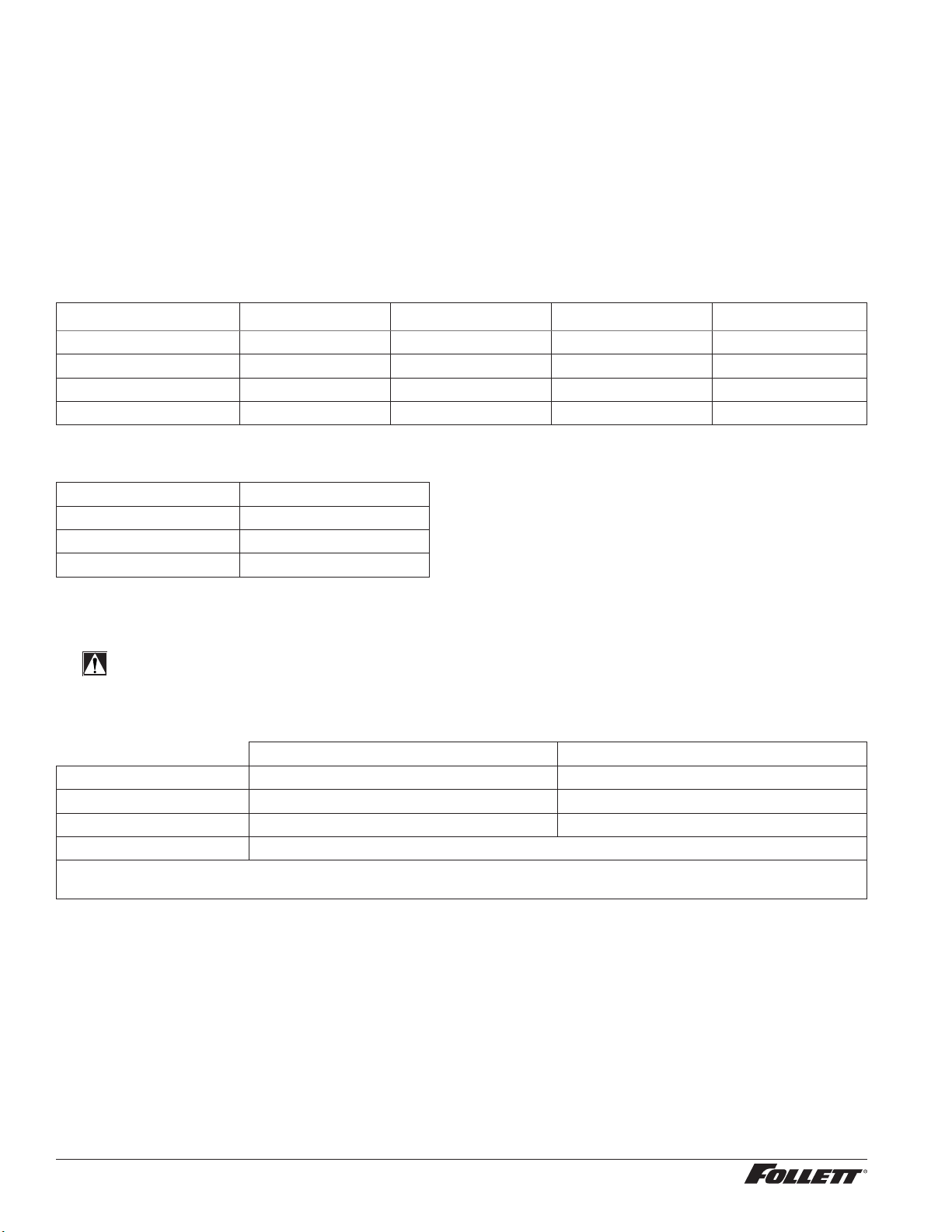
7CI100A 7FS100A 15CI100A 15FS100A
Width 14.50" (40 cm) 14.50" (36.8 cm) 14.50" (40 cm) 14.50" (40 cm)
Depth 22.12" (56.2 cm) 22.12" (56.2 cm) 23.50" (59.7 cm) 23.50" (59.7 cm)
Height 17.50" (44.5 cm) 41.88" (106.4 cm) 22.50" (57.2 cm) 46.75" (118.7 cm)
Unit Shipping Weight 90 lb (41 kg) 120 lb (54.4 kg) 100 lb (45.4 kg) 130 lb (60 kg)
Carbonator Dimensions
Width 10.25" (26.01 cm)
Depth 16.38" (41.6 cm)
Height 16.38" (41.6 cm)
Unit Shipping Weight 58.5 (26.5 kg)
Ambient Information
CAUTION!
The 7CI100A/7FS100A and 15CI100A/15FS100A are for indoor use only.
Designed for commercial use. Follett is not able to provide in-house services
for residential installations.
Maximum* Minimum*
Air Temperature
Water Temperature 90 F (32.2 C) 40 F (4.5 C)
Water Pressure 70 psi (483 kpa) 10 psi (69 kpa)
Relative Humidity 55% at 78 F (25.5 C)
* Use outside of these limitations is misuse and will void warranty.
† Best performance is achieved between 80 F (27 C) and 50 F (10 C).
†
100 F (38 C) 50 F (10 C)
Plumbing
§ Water Inlet: 1/4" OD push-to-connect
§ Optional Drain Accessory Kit (item# 00956375 or 00981977): 1/2" ID tubing
§ Water shut-off recommended within 5 ft. (1.5 m) of dispenser
6 Sparkling Ice and Water Dispenser 7CI100A/7FS100A, 15CI100A/15FS100A
Page 7
Specications –––––––––––––––––––––––––––––––––––––––––––––––––––––
Water
WARNING!
Connect to potable water supply only.
§ Water Mineral Content:
– TDS: greater than 80 ppm (mg/l) but less than 400 ppm (mg/l)
– Hardness: Less than 200 mg/l (12 gpg)
§ Not recommended for use with softened water
Clearances
§ 3" (77 mm) behind and on each side of dispenser for electrical and connection and ventilation
§ 4" (101.6 mm) around chiller/carbonator
Electrical
§ 115V, 60 Hz, 1 phase, 6.5A, maximum fuse 15A
§ Connect to dedicated 15A circuit, fuse or breaker
§ Must be grounded - requires 3-prong outlet. Do not remove ground.
Refrigeration
WARNING!
Do not damage the refrigerant circuit. Refrigerant can cause personal injury and/or damage dispenser.
Refrigerant R134a
§ Dispenser: 7.6 ounces (215 grams)
§ Chiller/Carbonator: 1.94 ounces (55 grams)
Heat Rejection
§ 1700 BTU/hr (498 W) - dispenser
§ 450 BTU/hr (132 W) - chiller/carbonator
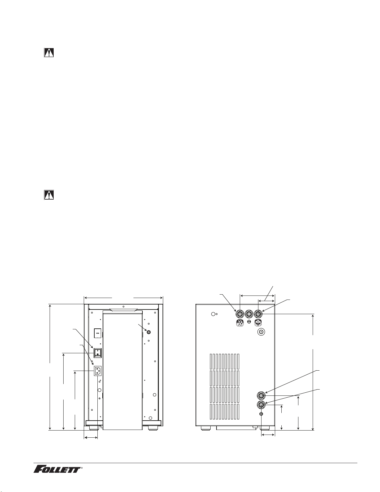
Chiller/Carbonator Detailed Drawing
10.25"
(26 cm)
POWER
SWITCH
IEC
POWER CORD
CONNECTION
16.38"
(41.6 cm)
10.00"
(25.4 cm)
7.69"
(19.5 cm)
T-STAT
SPARKLING
WATER OUT
1/4” PUSHTO-CONNECT
4.50"
(11.4 cm)
2.19" (5.6 cm)
STILL
WATER OUT
1/4” PUSHTO-CONNECT
4.50"
(11.4 cm)
3.31"
(8.4 cm)
15.06"
(38.3 cm)
WATER
INLET
1/4” PUSHTO-CONNECT
CO2 GAS
1/4” PUSHTO-CONNECT
1.75" (4.4 cm)
ALL CARFBONATOR CONNECTIONS ARE 1/4" PUSH TO CONNECT
1.75" (4.4 cm)
Sparkling Ice and Water Dispenser 7CI100A/7FS100A, 15CI100A/15FS100A 7
Page 8
Specications (continued) ––––––––––––––––––––––––––––––––––––––––––––––
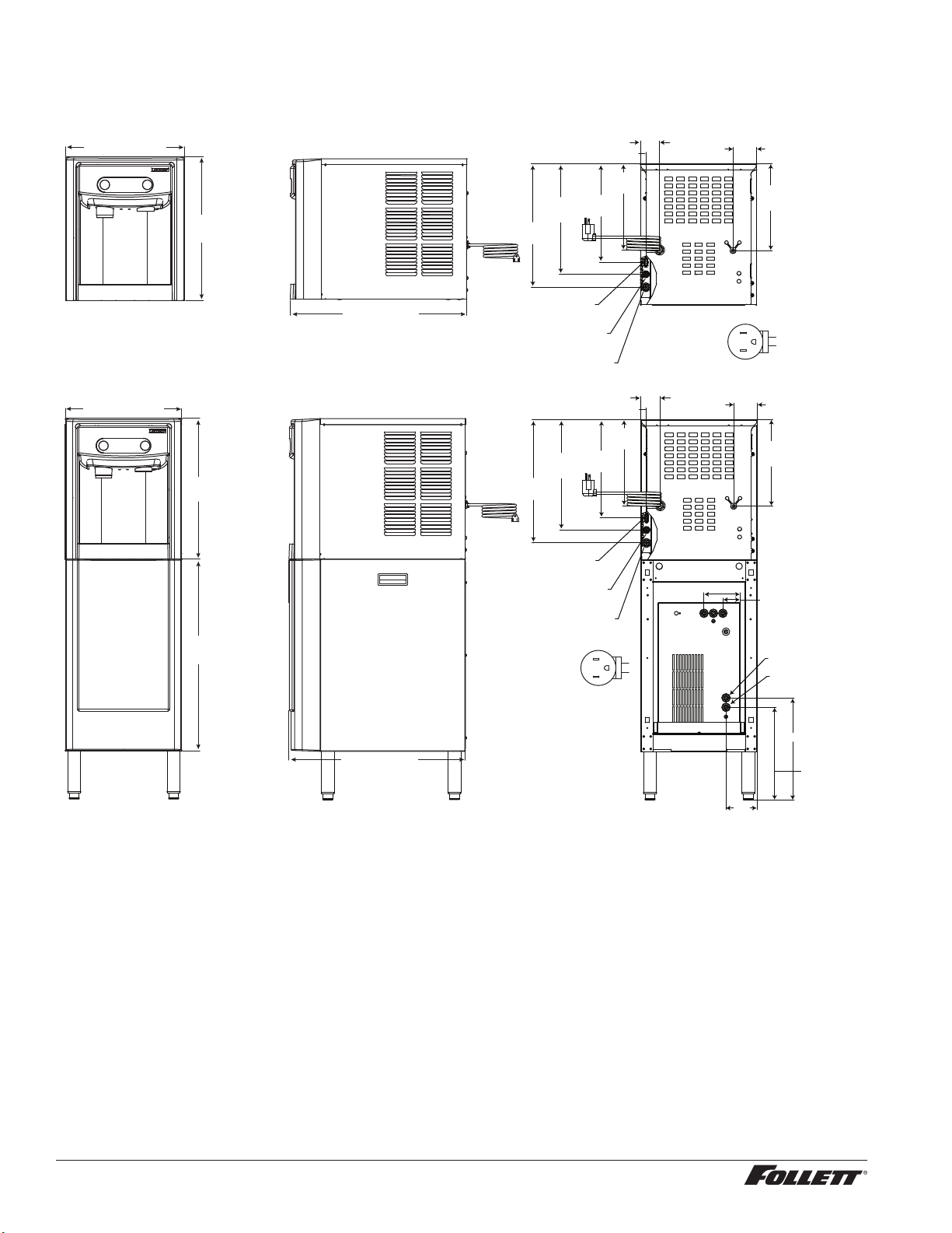
7 Series Detailed Drawing
Countertop models
14.50" (36.8 cm)
Freestanding models
14.50" (36.8 cm)
17.50"
(44.5 cm)
17.50"
(44.5 cm)
24.38"
(61.9 cm)
22.12" (56.2 cm)
13.75"
(34.9 cm)
15.38"
(39.1 cm)
CHILLER/CARBONATOR
POWER CORD CONNECTION
SPARKLING WATER INLET
1/4" PUSH TO CONNECT
STILL WATER INLET 3/8"
PUSH TO CONNECT
13.75"
(34.9 cm)
15.38"
(39.1 cm)
CHILLER/CARBONATOR
POWER CORD CONNECTION
SPARKLING WATER INLET
1/4" PUSH TO CONNECT
STILL WATER INLET 3/8"
PUSH TO CONNECT
NEMA 5-15
right angle
0.69" (17.5 mm)
10.75"
(27.3 cm)
12.25"
(31.1 cm)
0.69" (17.5 mm)
10.75"
(27.3 cm)
12.25"
(31.1 cm)
L2
G
L1
2.38" (6 cm)
NEMA 5-15
right angle
2.38" (6 cm)
4.50" (11.4 cm)
2.94" (7.5 cm)
10.81"
(27.5 cm)
L2
G
L1
2.94" (7.5 cm)
10.81"
(27.5 cm)
2.19" (5.6 cm)
WATER INLET 1/4"
PUSH TO CONNECT
CO2 INLET 1/4" PUSH
TO CONNECT
22.12" (56.2 cm)
8 Sparkling Ice and Water Dispenser 7CI100A/7FS100A, 15CI100A/15FS100A
3.94"
(10.0 cm)
12.75" (32.3 cm)
11.56" (29.4)
Page 9
Specications (continued) ––––––––––––––––––––––––––––––––––––––––––––––
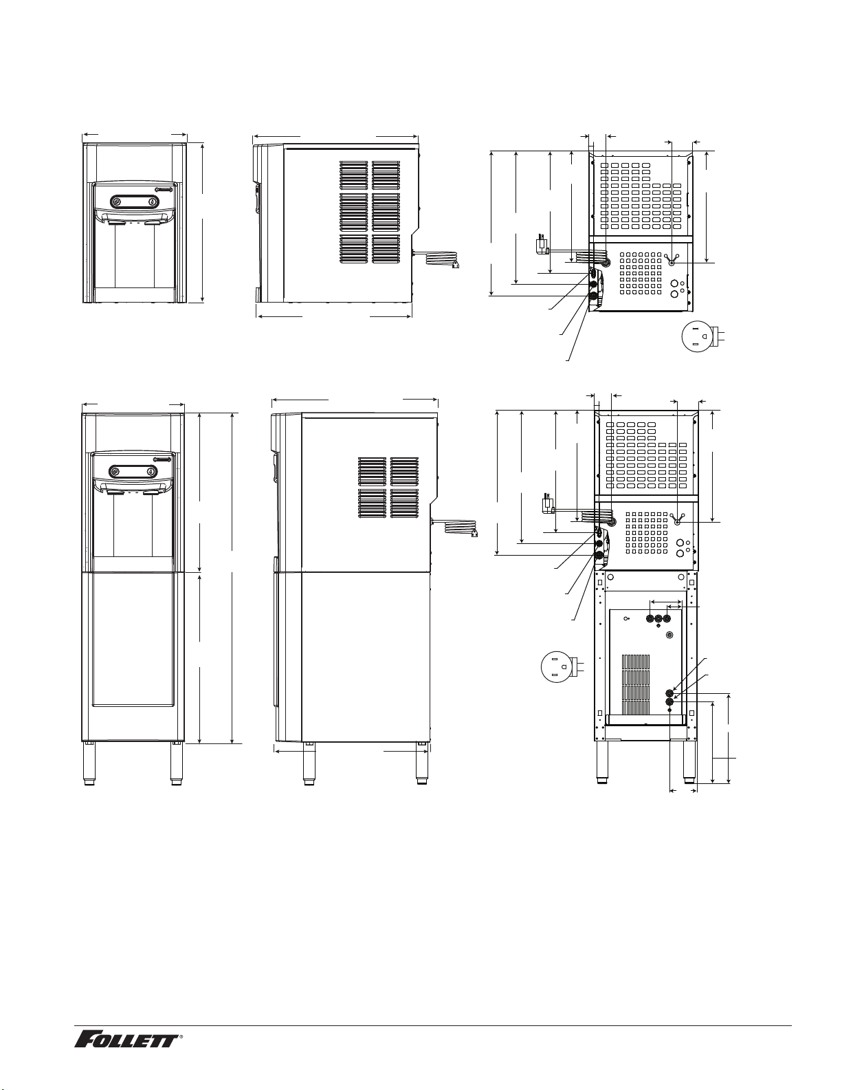
15 Series Detailed Drawing
Countertop models
14.50" (36.8 cm)
22.50"
(57.2 cm)
Freestanding models
14.50" (36.8 cm)
22.38"
(56.8 cm)
23.50" (59.7 cm)
22.12" (56.2 cm)
23.50" (59.7 cm)
18.63"
(47.3 cm)
20.25"
(51.4 cm)
CHILLER/CARBONATOR
POWER CORD CONNECTION
SPARKLING WATER INLET
1/4" PUSH TO CONNECT
STILL WATER INLET 3/8"
PUSH TO CONNECT
18.63"
(47.3 cm)
20.25"
(51.4 cm)
0.69" (17.5 mm)
15.63"
(39.2 cm)
17.53"
(43.5 cm)
0.69" (17.5 mm)
15.63"
(39.2 cm)
17.53"
(43.5 cm)
2.38" (6 cm)
NEMA 5-15
right angle
2.38" (6 cm)
2.94" (7.5 cm)
15.69"
(39.9 cm)
L2
G
L1
2.94" (7.5 cm)
15.69"
(39.9 cm)
24.38"
(61.9 cm)
46.75"
(118.7 cm)
22.12" (56.2 cm)
CHILLER/CARBONATOR
POWER CORD CONNECTION
SPARKLING WATER INLET
1/4" PUSH TO CONNECT
STILL WATER INLET 3/8"
PUSH TO CONNECT
NEMA 5-15
right angle
4.50" (11.4 cm)
L2
G
L1
3.94"
(10.0 cm)
2.19" (5.6 cm)
WATER INLET 1/4"
PUSH TO CONNECT
CO2 INLET 1/4" PUSH
TO CONNECT
12.75" (32.3 cm)
11.56" (29.4)
Sparkling Ice and Water Dispenser 7CI100A/7FS100A, 15CI100A/15FS100A 9
Page 10
Installation ––––––––––––––––––––––––––––––––––––––––––––––––––––––––
CAUTION!
No service or maintenance should be performed until the technician
has thoroughly read this service manual. Except for routine cleaning
and sanitizing, only qualied technicians should attempt to service
or maintain this equipment.
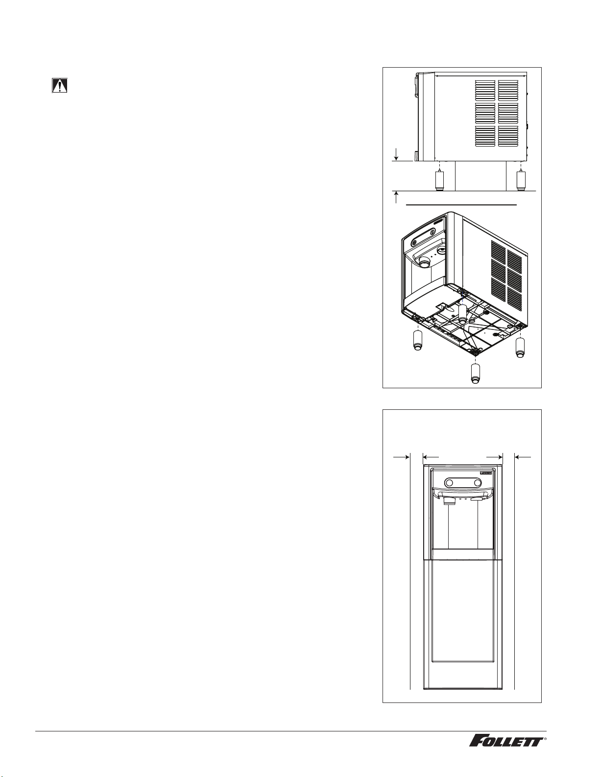
Countertop Installation
The 7 Series countertop model is designed to t on counters underneath
standard mounted cabinets, this does not apply to 15 Series models or
any model using optional leg accessory. See page 6 for dimensions.
Installation instructions for freestanding model may be found on page 12.
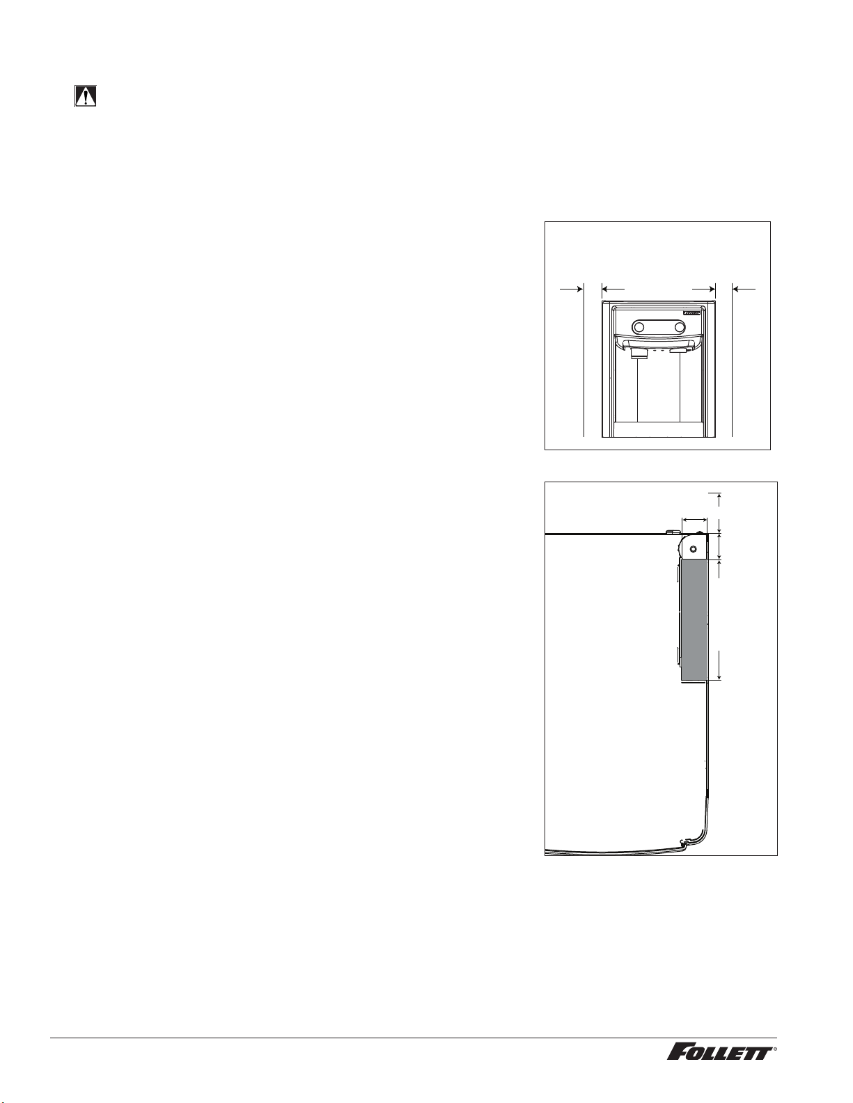
1. A clearance of at least 3" (77 mm) is required behind and on
each side of the dispenser for electrical connection and ventilation
(Fig.1).
2. Position dispenser in desired nal location and trace opening for
countertop cutout (right-side panel must be removed) or use Fig. 2
to locate cutout.
3. Use appropriate tool to make cutout.
Fig. 1
countertop models
minimum 3" (77 mm)
clearance required
Fig. 2
REQUIRED CLEARANCE
1.76" (4.5 cm)
3" (7.6 cm)
1.81"
(4.6 cm)
8.28" (21 cm)
10 Sparkling Ice and Water Dispenser 7CI100A/7FS100A, 15CI100A/15FS100A
Page 11

4. Position chiller/carbonator in cabinet (allow for required clearances, 4" on sides and back) and mark for
toe-kick recess cutout (Fig. 3).
5. Use appropriate tool to make toe-kick recess cutout.
6. Rough-in the electrical service and water line(s).
§ Electrical: 115V, single phase, 15A receptacle required. The dispenser has an integral 8 ft. (2.4 m) cord and
plug. The chiller/carbonator connects to the dispenser via a supplied 6 ft. power cord.
§ Water: supply line (with shut-off valve) connects to the dispenser's 1/4" NPT male inlet. A tee tting can be
employed to supply both the dispenser and chiller/carbonator from a single shut-off valve. Alternatively, a
second supply line (with shut-off valve) can be installed within the cabinet for the chiller/carbonator's 1/4"
push-to-connect inlet.
NOTICE!
If installing optional Drip Tray Drain Kit or Leg Accessory, complete those steps before proceeding.
Refer to instructions included with the Drip Tray Drain Kit, or see page 12 for Leg Accessory
instructions.
Fig. 3
CUTOUT FOR DISPENSER
COUNTERTOP
VENTILATION CUTOUT TO BE
PLACED OVER KICK RECESS AND
ALIGNED WITH VENT SHROUD
7. Place chiller/carbonator unit on oor in front of dispenser.
8. Follow the Final Connections instructions for countertop models that follows.
1.47"
5.13"
Sparkling Ice and Water Dispenser 7CI100A/7FS100A, 15CI100A/15FS100A 11
Page 12
Installation (continued) –––––––––––––––––––––––––––––––––––––––––––––––––
Optional Leg Accessory Installation
CAUTION!
Use caution when tipping the dispenser during leg installation. Do
not lay unit on back or side. DO NOT EXCEED 30° angle. Tipping
more than 30° can result in compressor malfunction.
1. If installing optional 4" Leg Accessory (item# 00956300), place a 5"
(127 mm) spacer underneath the dispenser to ease installation.
2. Remove four plastic, thread-protecting plugs from bottom of
dispenser.
3. Screw each leg into chassis (Fig. 4).
Fig. 4
5" (127 mm)
min.
spacer
Freestanding Installation
Installation instructions for countertop model may be found on Countertop
Installation on page 10.
1. A clearance of at least 3" (77 mm) is required behind and on
each side of the dispenser for electrical connection and ventilation
(Fig.5).
2. Rough-in the electrical service and water line(s).
§ Electrical: 115V, single phase, 15A receptacle required. The dispenser
has an integral 8 ft. (2.4 m) cord and plug. The chiller/carbonator
connects to the dispenser via a supplied power cord.
§ Water: supply line (with shut-off valve) connects to 1/4" push-to-
connect Tee that splits the supply to the dispenser and chiller/
carbonator (also 1/4" push-to-connect).
Fig. 5
freestanding models
minimum 3" (77 mm)
clearance required
12 Sparkling Ice and Water Dispenser 7CI100A/7FS100A, 15CI100A/15FS100A
Page 13
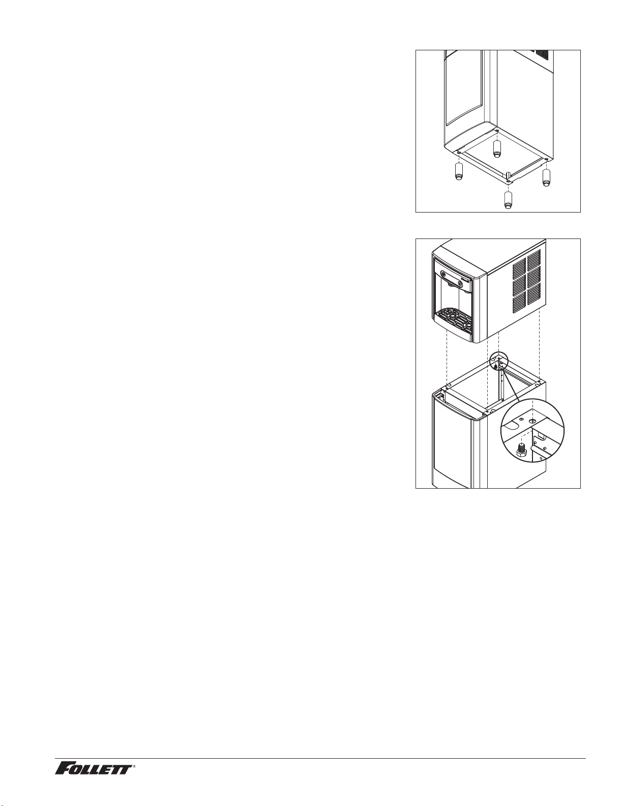
1. To install 6" Leg Accessory (item# 00956318), tilt or lay base stand
on side and screw each leg into stand (Fig.6).
Fig. 6
2. Remove four plastic, thread-protecting plugs from bottom of
dispenser.
3. Attach dispenser to base stand with supplied hardware (Fig. 7).
NOTICE!
If installing optional Drip Tray Drain Kit, refer to instructions
included with the Drip Tray Drain Kit.
4. Place chiller/carbonator unit on oor in front of dispenser.
5. Follow the Final Connections instructions for countertop models that
follows.
Fig. 7
X4
Sparkling Ice and Water Dispenser 7CI100A/7FS100A, 15CI100A/15FS100A 13
Page 14

Final Connections - Countertop Installation
1. Use 1/4" OD tubing to plumb incoming water (above countertop) to the tting on the rear of the dispenser
(Fig. 8.1).
2. Mount the Flood Prevention Valve bracket inside the cabinet. Refer to the instructions included with the
Flood Prevention Valve and set the Valve to the "2" position using the included key.
3. Use 1/4" OD tubing to plumb incoming water (below countertop) to the Flood Prevention Valve, assuring
the correct length so that it snaps into the mounting bracket (note proper ow direction) (Fig. 8.2).
4. Plumb to the Water Pressure Regulator (Fig. 8.3).
5. Then plumb to the Chiller/Carbonator (Fig. 8.4) assuring there is enough line that the Chiller/Carbonator
can be removed and set in front of the cabinet. Note proper ow direction for the devices and the Flood
Prevention Valve must be mounted vertically.
6. Remove the right side panel of the dispenser (see Page 24) to expose the Chiller/Carbonator connections.
7. Install the insulated Sparkling and Chilled Still water lines and the power cord to the dispenser, routing the
lines down through the cutout in the countertop (Fig. 8.5).
Note: Water lines are supplied at 6 ft. lengths. Note the Chilled Still water is 3/8" OD tubing and the Sparkling
water is 1/4" OD tubing.
8. Install the plug in the center Ambient Water Out of the Chiller/Carbonator (Fig. 8.6).
9. Connect the Chilled Still water 3/8" OD tubing to the Chiller/Carbonator (Fig. 8.7).
10. Connect the Sparkling water 1/4" OD tubing to the Chiller/Carbonator (Fig. 8.8).
11. Install the tube tting and are washer onto the CO2 regulator. Install the CO2 pressure regulator onto
the CO2 tank. Make sure that the CO2 tank is installed in a location with appropriate tipping prevention
according to local codes. Installing an OSHA approved cylinder rack with chain in an adjacent cabinet with
easy access for cylinder change-outs is recommended.
12. Install 1/4" OD LLDPE tubing from the regulator to the back of the Chiller/Carbonator (Fig. 8.9).
13. Leave the shutoff valve in the OFF position and open the cylinder valve. Using a at blade screwdriver
adjust the CO2 pressure to 60 psi on the top gauge. (The CO2 cylinder is not supplied and is the
responsibility of the customer.)
14. Turn on water and leave CO2 off. Make sure all water valves are open and check for leaks.
15. Plug in the dispenser but do not turn Chiller/Carbonator on at this point.
16. Dispense 1 liter Still water from the dispenser, then dispense 1 liter Sparkling water (Note: at this point,
the water will not be carbonated).
1 7. Remove the screw from the Chiller/Carbonator top panel (Fig. 8.10) and remove top panel (Fig. 8.11).
18. Pull the Chiller/Carbonator safety valve ring (Fig. 8.12) until water starts to come out of the side of the
tting and release immediately. It may take up to a minute for water to run from the safety valve. Reinstall
Chiller/Carbonator top panel.
Note: This procedure is required to remove an air bubble upon initial installation which can prevent the machine
from functioning properly. If air is trapped, the carbonation pump will continue running and eventually fault.
This requires a power cycle to reset.
19. Open the CO2 valve on the CO2 regulator and turn ON the power switch on the front of the Chiller/
Carbonator. Make sure the thermostat on the front of the Chiller/Carbonator is set to the coldest position
(7). Dispense Sparkling water until you hear the Chiller/Carbonator pump turn on (Note: the pump is very
quiet). The pump should turn off again within a few seconds depending on how much carbonated water
is dispensed. Perform at least 3 dispenses to cycle the pump and assure there is no trapped air in the
system.
20. Install Chiller/Carbonator cradle into cabinet. Slide Chiller/Carbonator into cabinet between the cradle
opening and assure the Chiller/Carbonator exhaust shroud is located above the cutout in the toe-kick
recess. Allow 2-4 hours for the Chiller/Carbonator to reach temperature.
14 Sparkling Ice and Water Dispenser 7CI100A/7FS100A, 15CI100A/15FS100A
Page 15
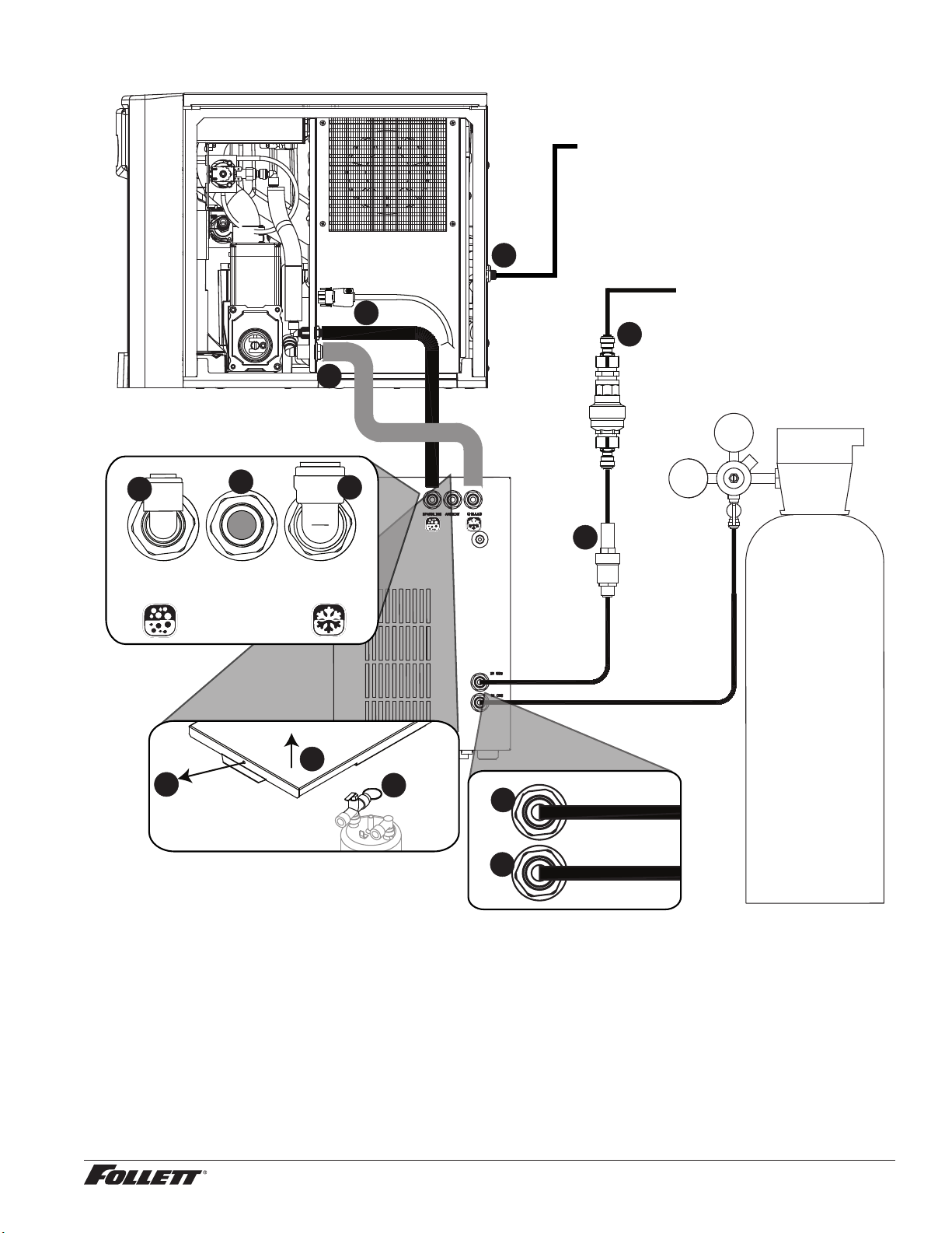
Fig. 8
IN H2O
IN CO2
10
11
12
SPARKLING
OUT
AMBIENT CHILLED
OUT
7
6
8
INCOMING
WATER (above counter,
for ice production)
1
INCOMING
WATER (below counter,
5
2
5
FLOOD
PREVENTION
for chilled and sparkling
water)
CO2 REGULATOR
VALVE*
3
WATER
PRESSURE
REGULATOR
CO2
TANK
4
* Flood Prevention Valve must be set to “2” and
mounted vertically - see instructions included
with Valve.
9
Sparkling water draining procedure
1. Turn off carbonator power and incoming water.
2. Dispense all Sparkling Water until only CO2 comes out (approx. 32 oz.)
3. Turn off CO2 and dispense from Sparkling button to evacuate remaining CO2.
4. Disconnect water, CO2 and power from carbonator.
Sparkling Ice and Water Dispenser 7CI100A/7FS100A, 15CI100A/15FS100A 15
Page 16
Final Connections - Freestanding Installation
1. Mount the Flood Prevention Valve bracket to the rear of the base stand (Fig.9.1).
2. Refer to the instructions included with the Flood Prevention Valve and set the Valve to the "2" position
using the included key.
3. Use 1/4" OD tubing to plumb incoming water to the tee tting (Fig. 9.2).
4. Use 1/4" OD tubing to plumb from the tee tting to the tting on the rear of the dispenser (Fig. 9.3).
5. Use 1/4" OD tubing to plumb from the tee to the Flood Prevention Valve, assuring the correct length so
that it snaps into the mounting bracket (note proper ow direction) (Fig. 9.4).
6. Use 1/4" OD tubing to plumb to the Water Pressure Regulator (Fig. 9.5).
7. Then plumb to the Chiller/Carbonator (Fig. 9.6) assuring there is enough line that the Chiller/Carbonator
can be removed and set in front of the base stand.
8. Remove the right side panel of the dispenser (see Page 24) to expose the Chiller/Carbonator connections.
Cut a 1.25" length of the rubber edging. Install the 1.25" length on the short edge of the base stand pass
through (Fig.9.7) and the remaining 6.75" length on the long edge (Fig. 9.8).
9. Install the insulated Sparkling and Chilled Still water lines and the power cord to the dispenser, routing the
lines down through the base stand (Fig. 9.9).
Note: Water lines are supplied at 6 ft. lengths, but can be trimmed to 4 ft. length for freestanding applications. Note
the Chilled Still water is 3/8" OD tubing and the Sparkling water is 1/4" OD tubing.
10. Install the plug in the center Ambient Water Out of the Chiller/Carbonator (Fig. 9.10).
11. Connect the Chilled Still water 3/8" OD tubing to the Chiller/Carbonator (Fig. 9.11).
12. Connect the Sparkling water 1/4" OD tubing to the Chiller/Carbonator (Fig. 9.12).
13. Install the tube tting and are washer onto the CO2 regulator. Install the CO2 pressure regulator onto
the CO2 tank. Make sure that the CO2 tank is installed in a location with appropriate tipping prevention
according to local codes. Installing an OSHA approved cylinder rack with chain in an adjacent cabinet with
easy access for cylinder change-outs is recommended.
14. Install 1/4" OD LLDPE tubing from the regulator to the back of the Chiller/Carbonator (Fig. 9.13).
15. Leave the shutoff valve in the OFF position and open the cylinder valve. Using a at blade screwdriver
adjust the CO2 pressure to 60 psi on the top gauge. (The CO2 cylinder is not supplied and is the
responsibility of the customer.)
16. Turn on water and leave CO2 off. Make sure all water valves are open and check for leaks.
1 7. Plug in the dispenser but do not turn Chiller/Carbonator on at this point.
18. Dispense 1 liter Still water from the dispenser, then dispense 1 liter Sparkling water (Note: at this point,
the water will not be carbonated).
19. Remove the screw from the Chiller/Carbonator top panel (Fig. 9.14) and remove top panel (Fig. 9.15).
20. Pull the Chiller/Carbonator safety valve ring (Fig. 9.16) until water starts to come out of the side of the
tting and release immediately. It may take up to a minute for water to run from the safety valve. Reinstall
Chiller/Carbonator top panel.
Note: This procedure is required to remove an air bubble upon initial installation which can prevent the machine
from functioning properly. If air is trapped, the carbonation pump will continue running and eventually fault.
This requires a power cycle to reset.
2 1. Open the CO2 valve on the CO2 regulator and turn ON the power switch on the front of the Chiller/
Carbonator. Make sure the thermostat on the front of the Chiller/Carbonator is set to the coldest position
(7). Dispense Sparkling water until you hear the Chiller/Carbonator pump turn on (Note: the pump is very
quiet). The pump should turn off again within a few seconds depending on how much carbonated water
is dispensed. Perform at least 3 dispenses to cycle the pump and assure there is no trapped air in the
system.
22. Install Chiller/Carbonator cradle into base stand. Slide Chiller/Carbonator into base stand between the
cradle opening and assure the Chiller/Carbonator exhaust shroud is located above the cutout in the base
stand. Install the front Chiller/Carbonator retaining brackets into the base stand and replace the base
stand cover. Allow 2-4 hours for the Chiller/Carbonator to reach temperature.
16 Sparkling Ice and Water Dispenser 7CI100A/7FS100A, 15CI100A/15FS100A
Page 17
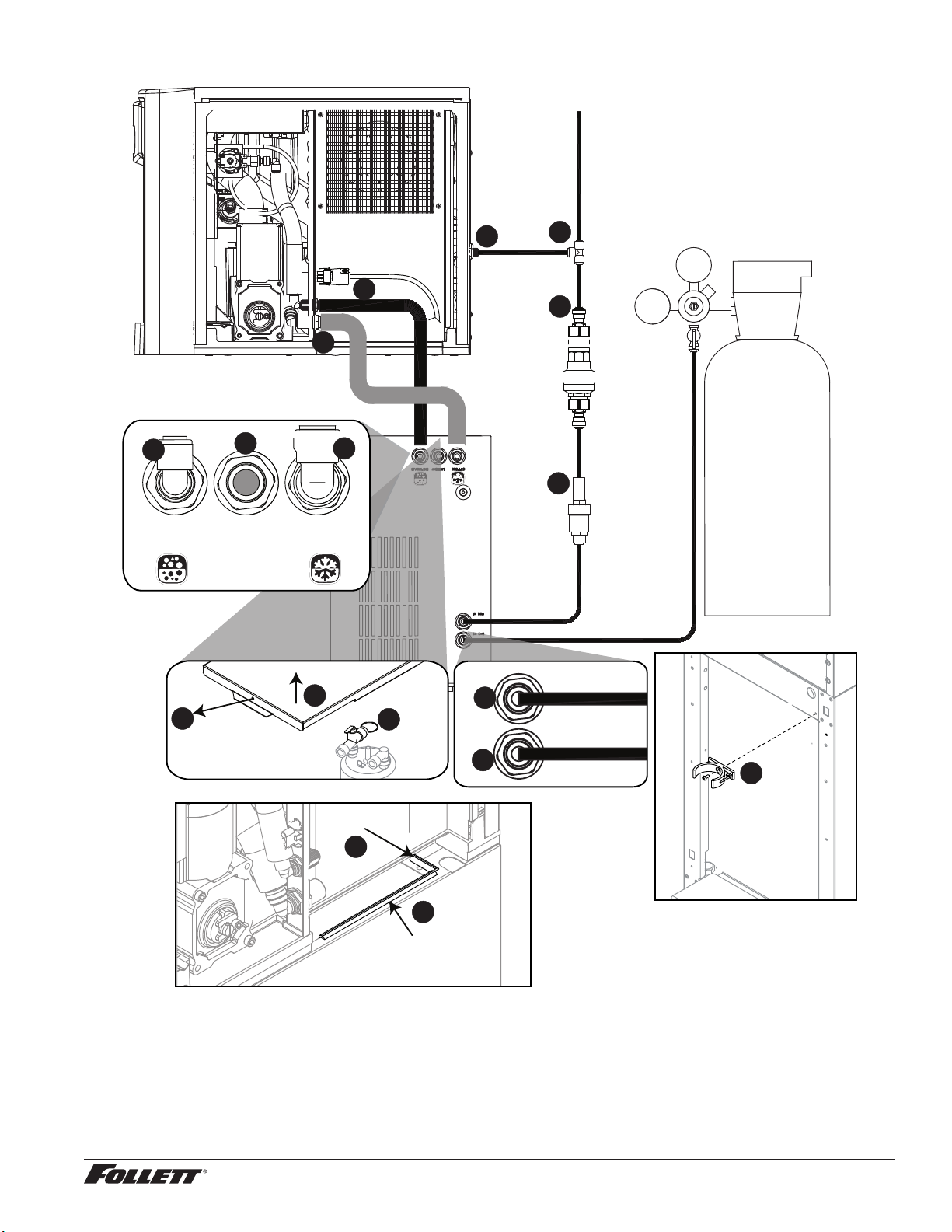
Fig. 9
IN H2O
IN CO2
14
15
16
SPARKLING
OUT
AMBIENT CHILLED
OUT
11
10
12
INCOMING
WATER
3
9
9
2
4
CO2 REGULATOR
FLOOD
PREVENTION
VALVE*
CO2
TANK
5
WATER
PRESSURE
REGULATOR
6
13
1
1.25" length
7
8
6.75" length
* Flood Prevention Valve must be set to “2” and
mounted vertically - see instructions included
with Valve.
Sparkling water draining procedure
1. Turn off carbonator power and incoming water.
2. Dispense all Sparkling Water until only CO2 comes out (approx. 32 oz.)
3. Turn off CO2 and dispense from Sparkling button to evacuate remaining CO2.
4. Disconnect water, CO2 and power from carbonator.
Sparkling Ice and Water Dispenser 7CI100A/7FS100A, 15CI100A/15FS100A 17
Page 18
Installation (continued) –––––––––––––––––––––––––––––––––––––––––––––––––––––––––––––––––––––
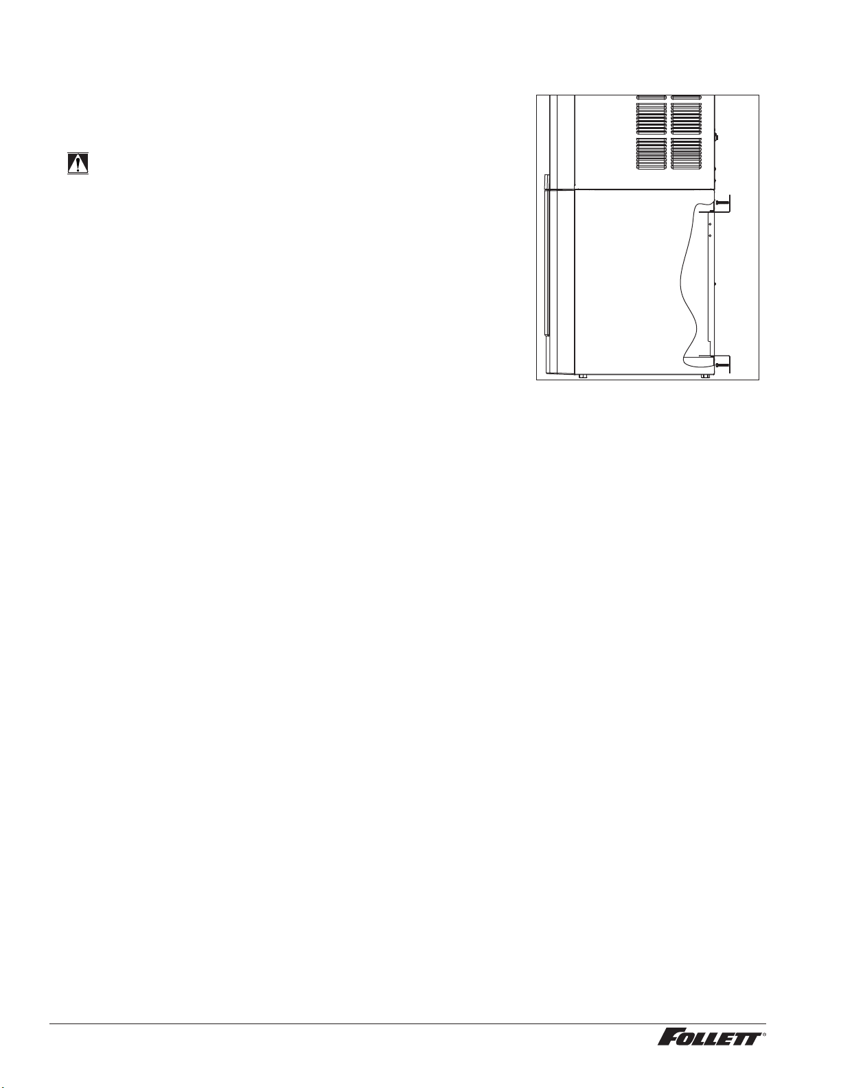
5. Secure unit to wall or cove molding with supplied bracket (Fig. 10) to
prevent tipping.
Note: Fasteners must be supplied by installer.
WARNING!
Freestanding unit must be secured to wall to prevent tipping.
Failure to do could result in personal injury or damage to the
unit.
Fig. 10
18 Sparkling Ice and Water Dispenser 7CI100A/7FS100A, 15CI100A/15FS100A
Page 19

Maintenance/Cleaning Mode –––––––––––––––––––––––––––––––––––––––––
Cleaning Mode (Dispensing Disabled) - Use when cleaning surface
Entering Cleaning Mode disables the User Interface and allows you to clean
the outside of the dispenser without accidentally dispensing.
1. To enter Cleaning Mode, press and immediately release the
maintenance/clean switch (Fig. 11.1) so that only "FRESH
FILTERED ICE AND WATER" displays in the user interface
(Fig.11.2).
2. To exit Cleaning Mode, press and immediately release the
maintenance/clean switch so that the ice and water icons also
display in the user interface.
Maintenance Mode (All Operations Disabled) - Use when cleaning ice
machine
Entering Maintenance Mode disables all operations and allows you to safely
clean and/or sanitize the icemaker and dispenser.
1. To enter Maintenance Mode, press and hold the maintenance/
clean switch (Fig. 11.3) until displays in the user interface
(Fig.11.4).
2. To exit Maintenance Mode, press and hold the maintenance/clean
switch until
Note: Entering and exiting Maintenance Mode will reset the six-month
periodic maintenance reminder.
no longer displays in the user interface.
Fig. 11
2
1
4
3
Accessing Internal Components ––––––––––––––––––––––––––––––––––––––
Fig. 12
CAUTION!
Except for routine cleaning and sanitizing, only qualied
technicians should attempt to service or maintain this equipment.
1. Press and hold the maintenance/clean switch (Fig. 12.1) until
displays in the user interface (Fig. 12.2).
2. Remove (unscrew) chrome ice dispenser chute (Fig. 12.1).
3. Remove the drip tray (Fig. 12.2).
4. Remove the two screws (Fig. 12.3) on the front panel (behind the
drip tray).
5. Remove and set aside the front panel (Fig. 12.4) - do not
disengage the plug on the back of the User Interface or the
tubing at the water dispenser chute (if so equipped).
2
4
1
3
Sparkling Ice and Water Dispenser 7CI100A/7FS100A, 15CI100A/15FS100A 19
Page 20

DIP-switch Settings –––––––––––––––––––––––––––––––––––––––––––––––––
The time delay and the six-month maintenance reminder can be set.
1. Remove the front panel as explained in Accessing Internal
Components on page 19 then refer to Fig. 13.
2. Remove top panel (Fig. 13.1).
Note: For 15 Series dispensers, the right side panel must also be
removed.
3. Remove (1) screw and top of control board enclosure (Fig. 13.2).
4. Locate the DIP switches on the dispenser's control board (Fig. 14).
OFF ON
Not used (OFF position)
Ice only
No internal filter
Not used (OFF position)
15 minute delay
Not used (OFF position)
Six-month PM enabled
1 2 3 4 5 6 7 8
Ice & water
Internal filter supplied or to display "Fresh Filtered"
Sparkling water
30 minute delay
Six-month PM disabled
Fig. 13
1
2
Fig. 14
20 Sparkling Ice and Water Dispenser 7CI100A/7FS100A, 15CI100A/15FS100A
Page 21

NSF-approved Cleaning and Sanitizing Procedure –––––––––––––––––––––––
Cleaning and sanitizing should be performed at least every 6 months (more often
if local water conditions dictate).
Follett recommends cleaning/sanitizing the chiller/carbonator on a regular basis
using P/N 01147545.
WARNING!
§ Place the dispenser in Maintenance Mode prior to servicing or
cleaning the ice machine. See Maintenance/Cleaning Mode on
page 19.
§ For protection, rubber gloves and safety goggles (and/or face shield)
should be worn when handling SafeCLEAN Plus™.
§ Do not use bleach, it will damage the dispenser.
Required Supplies
§ 7 Series: 24 oz. (0.71 L) of SafeCLEAN Plus liquid
15 Series: 48 oz. (1.42 L) of SafeCLEAN Plus liquid
§ Funnel and Bucket
Ice machine and Dispenser
1. Dispense all the ice out of the unit.
2. Press and hold maintenance/clean switch until displays in the user
interface to enter Maintenance Mode.
3. Remove (unscrew) chrome ice dispense chute (Fig. 15.1).
4. Remove drip tray (Fig. 15.2).
5. Remove (2) screws located behind the drip tray (Fig. 15.3).
6. Move front panel and place on top or beside unit (Fig. 15.4).
7. Remove plug cap from the end of drain tube (Fig. 15.5) and lower tube
to drain water into bucket. After the system has been drained of water
replace plug cap in drain tube.
8. Secure tube in holder.
9. Remove cap from bin lid cover (Fig. 15.6).
10. Screw bin lid cover cap onto ice discharge chute (Fig. 15.7).
Fig. 15
1
3
2
4
6
7
5
11. 7 Series: Mix 24 oz. (0.71 L) of SafeCLEAN Plus liquid with threegallons (11.4 L) of water.
15 Series: Mix 48 oz. (1.42 L) of SafeCLEAN Plus liquid with sixgallons (22.7 L) of water.
12. Pour SafeCLEAN Plus solution into bin lid access spout until solution reaches the spout neck.
13. Allow the SafeCLEAN Plus solution to remain in unit for 15 minutes.
14. While machine is cleaning, remove top and right side panel to access and clean air-cooled condenser.
15. Submerge ice dispense chute in the remainder of SafeCLEAN Plus solution for 2 minutes. Rinse with
clean, potable water.
16. Drain system by lowering drain tube into bucket.
1 7. Secure drain tube into holder.
18. Fill and drain twice with potable water. Secure drain tube.
19. Place a bucket under the dispense chute and remove cap. Note: Some SafeCLEAN Plus solution will
remain and drain out when cap is removed. Reposition cap on bin lid spout.
20. Reinstall front panel, ice dispense chute, and drip tray.
2 1. Press and hold maintenance/clean switch to exit Maintenance Mode.
Sparkling Ice and Water Dispenser 7CI100A/7FS100A, 15CI100A/15FS100A 21
Page 22

User Interface and Exterior Cabinet Cleaning
1. Press and release maintenance/clean switch so that only "FRESH FILTERED ICE AND WATER" displays
in the user interface to enter Cleaning Mode (and disable dispensing).
2. Plastic parts, including the user interface, can be cleaned with a non-abrasive glass cleaner. Clean
stainless steel panels with stainless steel cleaner.
3. Press and release maintenance/clean switch to put unit back into service.
Flow Straightener Cleaning/Sanitizing
4. Remove front panel (see Accessing Internal
Components section).
5. Remove the water tting from the John Guest
tting.
6. Remove two screws holding the ow
straightener.
7. Soak ow straightener in SafeCLEAN
Plus solution for 15 minutes, rinse, then
reassemble.
Chiller/Carbonator Sanitizing Instructions
Follett offers a chiller/carbonator sanitizing kit (order P/N 01147545).
1. Unplug dispenser and turn OFF water supply.
2. Install dip tube in the lter head.
3. Mix a 200 ppm active quaternary sanitizing solution of 1 gal. (3.8 L) 100F (38 C) water and 1.6 oz (47 ml)
Nu-Calgon IMS-III Sanitizer (P/N 00979674).
4. Fill lter bowl to just below the o-ring with sanitizing solution and screw lter bowl onto lter head.
5. Remove incoming water supply from Flood Prevention Valve and connect to the IN tting on lter head.
6. Remove outgoing water supply from Flood Prevention Valve and connect to the OUT tting on lter head.
7. Turn the incoming water ON.
8. Dispense 12 oz. from Chilled Still Water tap. You should see slight foaming, which ensures sanitizer has
completely lled lines. Discard water collected in container.
9. Dispense 16 oz. from the Sparkling Water tap. Discard water collected in container.
10. Allow carbonator pump to cycle.
11. Dispense an additional 16 oz Sparkling Water. Discard water collected in container.
12. Allow sanitizer to remain in water lines for at least 5minutes.
13. Turn OFF water supply.
14. Remove lter bowl and lter head from water circuit.
Note: The lter head, lter bowl and dip tube can be cleaned and re-used.
15. Re-connect Flood Prevention Valve and turn water ON.
16. Dispense 2 quarts from Chilled Still Water tap.
Note: Foaming will stop when Chilled Still Water line is completely ushed.
1 7. Flush the remaining sanitizer through the Sparkling Water tap in no greater than 1 quart increments.
Note: The carbonated sanitizer creates a signicant amount of foam.
18. When Sparkling Water no longer foams, ush an additional 2 quarts sparkling water.
19. Taste test to ensure there are no off avors from residual sanitizer. After this procedure any residual
sanitizer will not be at a high enough concentration to have any negative health effects.
22 Sparkling Ice and Water Dispenser 7CI100A/7FS100A, 15CI100A/15FS100A
Page 23

Service –––––––––––––––––––––––––––––––––––––––––––––––––––––––––––
Sleep cycle
LED Indicator Description
The LED Indicator is located behind the front panel.
Fig. 16
Clean
LED Name LED Color Description
Clean Green The dispenser is in Cleaning Mode. Dispenser is disabled to allow for cleaning of
— N/A Not used.
PM Red Six-month periodic maintenance required.
Drip tray Red Drip tray full.
Water leak Red Internal leak in dispenser.
High amps Red Auger gearmotor has exceeded 0.55A. The HI amps and Time delay LEDs will
Service Red 8000 hour bushing check (call Follett technical service group at (877) 612-5086 or
Maintenance Yellow Enter Maintenance Mode by pressing and holding maintenance/clean switch for 5
Low water Yellow Insufficient water supply to machine or no low bin LED upon startup.
Time delay Yellow Ice production will not resume for at least 15 minutes after a full bin is achieved and
Sleep cycle Green After a full bin and 10 minutes of non-use, the unit goes into standby and will not
Making ice Green Gearmotor, compressor, and fan motor energized.
Low bin Green Bin switch closed calling for ice.
Power on Green Power supplied to unit.
PM
Drip tray
Water leak
HI press
HI amps
Service
Maint
Low water
Time delay
front panel. See Maintenance/Cleaning Mode on page 19.
illuminate, the machine will shut down for one hour, the LEDs will turn off, and the
machine will resume normal operation.
+1 (610) 252-7301).
seconds. Unit will not make or dispense ice.
a minimum amount of dispense activity has elapsed.
produce ice until either:
7 Series:12 hours has elapsed, 15 Series: 4 hours has elapsed
or ice or water has dispensed.
Making ice
Low bin
Power ON
Sparkling Ice and Water Dispenser 7CI100A/7FS100A, 15CI100A/15FS100A 23
Page 24

Service (continued) ––––––––––––––––––––––––––––––––––––––––––––––––––––
Evaporator Disassembly
1. Disconnect power from the dispenser.
2. Turn off water supply to dispenser.
3. Remove (unscrew) chrome ice dispenser chute (Fig.17.1).
4. Remove the drip tray (Fig. 17.2).
5. Remove the two screws (Fig. 17.3) on the front panel
(behind the drip tray).
6. Remove and set aside the front panel (Fig. 17.4) - do not
disengage the plug on the back of the User Interface.
7. Lift and remove the top panel, set aside (Fig.17.5).
8. Remove two screws (Fig. 17.6) to remove left side panel.
9. Remove two screws (Fig. 17.7) to remove right side panel.
Fig. 17
2
1
1
3
2
4
6
5
7
24 Sparkling Ice and Water Dispenser 7CI100A/7FS100A, 15CI100A/15FS100A
Page 25

Service (continued) ––––––––––––––––––––––––––––––––––––––––––––––––––––
10. Unplug the gear motor (three connectors) (Fig.18).
11. Remove ground screw connection.
12. Remove gear motor:
§ Remove M6 allen screw, retainer, spacer and key (Fig. 19.1).
§ Remove two M6x90 allen screws (Fig. 19.2).
§ Pull gear motor from auger (Fig. 19.3).
§ Remove main housing insulation (Fig. 19.4).
13. Remove all traces of petro-gel from auger shaft.
Fig. 18
Fig. 19
14. Remove compression nozzle:
§ Loosen hose clamp (Fig.20.1).
§ Remove transport tube (Fig. 20.2).
4
2
3
1
2
Fig. 20
1
2
Sparkling Ice and Water Dispenser 7CI100A/7FS100A, 15CI100A/15FS100A 25
Page 26

Service (continued) –––––––––––––––––––––––––––––––––––––––––––––––––––
15. Remove M6 socket head allen screw (Fig.21.1).
16. Remove compression nozzle retainer (Fig. 21.2).
1 7. Remove compression nozzle (Fig. 21.3).
18. Remove main housing:
§ Disconnect vent line from T tting (Fig.22.1).
Fig. 21
1
2
3
Fig. 22
19. Remove three M6x25 socket head allen screws
(Fig.23.1).
20. Remove main housing (Fig. 23.2).
1
Fig. 23
2
1
26 Sparkling Ice and Water Dispenser 7CI100A/7FS100A, 15CI100A/15FS100A
Page 27

Service (continued) –––––––––––––––––––––––––––––––––––––––––––––––––––
3
2 1. Remove and discard mating ring and seal (Fig.24.1).
22. Carefully remove auger (Fig. 24.2).
WARNING!
Use caution when removing auger. The auger is very
sharp - handle with care to avoid personal injury.
Evaporator Assembly
1. Remove and inspect main housing O-ring seal. Replace if
damaged in any way.
2. Clean O-ring groove. Lubricate O-ring with Petro-gel and
reinstall.
3. Use cardboard disc to press new mating ring into main
housing (Fig. 25.1).
4. Lube the shaft with liquid soap in the area shown
(Fig.25.2) and slip on seal and spring (Fig. 25.3).
Note: Do not touch the sealing surfaces with bare hands.
Contact with bare skin will cause premature seal failure.
5. Install auger (Fig. 25.4).
Fig. 24
Fig. 25
Do NOT
touch!
1
Cardboard
disc
2
2
1
4
6. Install main housing:
Fig. 26
§ Slide main housing onto auger shaft (Fig.26.1).
§ Install three M6x25 allen screws (Fig.26.2).
§ Connect vent line to T tting (Fig.26.3).
2
3
1
Sparkling Ice and Water Dispenser 7CI100A/7FS100A, 15CI100A/15FS100A 27
Page 28

Service (continued) –––––––––––––––––––––––––––––––––––––––––––––––––––
7. Install compression nozzle:
§ Remove and inspect compression nozzle O-ring seal.
Replace if damaged in any way.
§ Clean O-ring groove. Lubricate O-ring with Petro-gel and
reinstall.
§ Install compression nozzle (Fig.27.1).
§ Install compression nozzle retainer (Fig.27.2).
§ Install M6 socket head allen screw (Fig.27.3).
8. Install transport tube (Fig. 28.1).
9. Tighten hose clamp (Fig.28.2).
Fig. 27
3
2
1
Fig. 28
2
10. Install gear motor:
§ Install main housing insulation (Fig.29.1).
§ Slide gear motor onto auger shaft (Fig.29.2).
§ Install two M6x90 allen screws (Fig. 29.3).
1
Fig. 29
1
3
2
3
28 Sparkling Ice and Water Dispenser 7CI100A/7FS100A, 15CI100A/15FS100A
Page 29

Service (continued) –––––––––––––––––––––––––––––––––––––––––––––––––––
11. Use screwdriver to orient auger shaft to align with motor
shaft keyway (Fig. 30.1).
12. Install key into keyway (Fig. 30.2).
13. Install spacer, ensure that key is captured in slot
(Fig.31.1).
Fig. 30
2
1
Fig. 31
1
14. Insert screwdriver into groove of auger shaft and pry shaft
outwards (Fig.32.1).
15. Insert retainer into groove (Fig.32.2), ensure that retainer
is aligned with hole in spacer.
Fig. 32
1
2
Sparkling Ice and Water Dispenser 7CI100A/7FS100A, 15CI100A/15FS100A 29
Page 30

Service (continued) –––––––––––––––––––––––––––––––––––––––––––––––––––
16. Install screw (Fig.33.1) and tighten (Fig.33.2). Fig. 33
2
1
1 7. Plug in gear motor (Fig.34).
§ BLUE to BLUE
§ BLACK to BLACK
§ WHITE to WHITE
§ Connect ground wire with ground screw.
Fig. 34
BLUE to BLUE
BLACK to BLACK
WHITE to WHITE
30 Sparkling Ice and Water Dispenser 7CI100A/7FS100A, 15CI100A/15FS100A
Page 31

Service (continued) ––––––––––––––––––––––––––––––––––––––––––––––––––––
Condenser Fan Motor Removal (7 Series Shown)
Sparkling Ice and Water Dispenser 7CI100A/7FS100A, 15CI100A/15FS100A 31
Page 32

Service (continued) ––––––––––––––––––––––––––––––––––––––––––––––––––––
Bin Melt Water/Evaporator Feed/Clean Out System Schematic
Storage Bin
Vent System Schematic
Vent Tube
Storage Bin
Reservoir
32 Sparkling Ice and Water Dispenser 7CI100A/7FS100A, 15CI100A/15FS100A
Page 33

Service (continued) ––––––––––––––––––––––––––––––––––––––––––––––––––––
Refrigeration Schematic - Dispenser
Sparkling Ice and Water Dispenser 7CI100A/7FS100A, 15CI100A/15FS100A 33
Page 34

Service (continued) ––––––––––––––––––––––––––––––––––––––––––––––––––––
Water Feed Schematic
SPARKLING WATER
DISPENSE SOLENOID
VALV E
STILL WATER
DISPENSE
SOLENOID VALVE
ICE MACHINE WATER
SOLENOID VALVE
WATER
CHUTE
EVAPORATOR
FLOAT
PREVENTION
WATER
SUPPLY
FLOOD
VALV E
PRESSURE
REGULATOR
34 Sparkling Ice and Water Dispenser 7CI100A/7FS100A, 15CI100A/15FS100A
Page 35

Service (continued) ––––––––––––––––––––––––––––––––––––––––––––––––––––
Chiller/Carbonator
COLD SPARKLING
WATER
COLD STILL
WATER
ROOM TEMPERATURE WATER
INLET WATER
IN CO2
Sparkling Ice and Water Dispenser 7CI100A/7FS100A, 15CI100A/15FS100A 35
Page 36

Service (continued) ––––––––––––––––––––––––––––––––––––––––––––––––––––
User Interface Display Identication
Operation Display
Condition
Normal
operation
Cleaning
Mode
Drip tray full Empty drip tray.
Press and release maintenance/
clean switch to clean the user
interface without dispensing ice or
water (see Maintenance/Cleaning
Mode on page 19).
Procedure
—
PM
Six-month
periodic
maintenance
required
Maintenance
Mode
Service -
8000 hr
bushing
check
Follow Maintenance Mode
procedure (below) and also see
NSF-approved Cleaning and
Sanitizing Procedure on page
21.
Enter Maintenance Mode by
pressing maintenance/clean switch
until
cleaning and sanitizing procedure
shown on page 21 and change
the lter, if so equipped. Exit
Maintenance Mode by pressing and
holding maintenance/clean switch
until
Call Follett Technical Service Group
at (877) 612-5086 or +1 (610) 252-
7301. The ashing wrench indicates
that the 8000 hr bushing check is
required.
displays. Complete the
no longer displays.
36 Sparkling Ice and Water Dispenser 7CI100A/7FS100A, 15CI100A/15FS100A
Page 37

Service (continued) ––––––––––––––––––––––––––––––––––––––––––––––––––––
Service Display Condition Procedure
Internal leak in
dispenser
Sleep mode Press either dispense button to
Locate leak and repair - Press
reset on control board. Contact
Follett if icemaker is leaking.
return to normal operation.
Sparkling Ice and Water Dispenser 7CI100A/7FS100A, 15CI100A/15FS100A 37
Page 38

Service (continued) ––––––––––––––––––––––––––––––––––––––––––––––––––––
Electrical Wiring Diagram - Dispenser
POWER
LOW BIN
MAKING ICE
SLEEP CYCLE
TIME DELAY
LOW WATER
MAINTENANCE
SERVICE
HI AMPS
HI PRESSURE
WATER LEAK
DRIP TRAY
PM
CLEAN
#2 WHITE
D1
D3
D2
COMPRESSOR
BLACK
#1
O.L.
C
S
GRN-YEL
#3
COMP.
R
START
RELAY
P16
P15
ICE AUX WATER AUX
T1
D6
D5
D4
S1
K1
D16
HI PRS
P14
#20 BLACK
D9
D8
D7
MODEL SELECT
D19D22D21D20
D11
D10
5
6
PROGRAM
1
P9
2
D37
D18
K3
D13
D12
RESET
S2
P10
SERIAL COMM
P17
WATER LEVELS
CURRENT SENS
D17
D14
RS485 UI
P7
D15
USER
SENSOR
DRIP TRAY WATER
MAINT.
BIN
INTERFACE
CLEAN
RESERVOIR
YELLOW
ORANGE
BLACK
WATER SENSOR
RS485 UI
P7
P8
P13
BIN
P12 P11
P11
BIN RS485
P12
P5
D48
T2
P4
AUGER
P17
WATER LEVELS
P18
GRN-YEL
#19
WATER SENSOR
CHASSIS
BLUE
#5
N
POWER
N N N N N N N N N
P2
#30 BLACK
L1
GND
#31 WHITE
#13
#32
WHITE
GRN-YEL
L1 L1L1
BLACK
#12
DISP.
P1
P21
#15 BLACK
GRN-YEL
#14
WHITE
#16
FAILSAFE SOLENOID VALVE
WATER DISPENSE VALVE
#18 WHITE
Not used (OFF position)
Ice only
No internal lter
P20
#17 BLACK
P19
#34 WHITE
OFF ON
#33 BLACK
CARBONATED WATER DISPENSE VALVE
P3P6P22
BLACK
FAN
BLACK
1 2 3 4 5 6 7 8
Ice & Water
"Fresh Filtered"
GRN-YEL
#4
Not used (OFF position)
Sparkling water
30 minute delay
Six month PM disabled
CARB/
POWER
CHILLER
OFF position
15 minute delay
Not used (OFF position)
Six month PM enabled
#7
BLUE/
WHITE/
#10
AUGER
CAP
BLUE
BLACK
#8
PINK
BLACK
GRN-YEL
#11
AUGER
GRAY
WHITE
38 Sparkling Ice and Water Dispenser 7CI100A/7FS100A, 15CI100A/15FS100A
Page 39

Service (continued) ––––––––––––––––––––––––––––––––––––––––––––––––––––
Electrical Wiring Diagram - Chiller/Carbonator
IEC PLUG
GREEN/YELLOW
BROWN
GREEN/YELLOW
BLUE
GREEN/YELLOW
MAIN SWITCH
BLUE
TERMINAL BLOCK
BLUE
CARBONATOR
BLUE
BLACK
RED
BLUE
BROWN
RED
BLACK
BLUE
PUMP
LEVEL
CONTROLLER
THERMOSTAT
BLUE
GREEN/YELLOW
BLUE
GREEN/YELLOW
COMPRESSOR
BROWN
BLUE
GREEN/YELLOW
FAN
BROWN
BLUE
Sparkling Ice and Water Dispenser 7CI100A/7FS100A, 15CI100A/15FS100A 39
Page 40

Parts –––––––––––––––––––––––––––––––––––––––––––––––––––––––––––––
7 Series Exterior
6
8 x2
4
8 x2
7
8 x4
5
2
1
40 Sparkling Ice and Water Dispenser 7CI100A/7FS100A, 15CI100A/15FS100A
3
9
Page 41

Parts (continued) ––––––––––––––––––––––––––––––––––––––––––––––––––––––
Exterior
Reference # Description Part #
1 Drip Tray Assy 00957613
2 Panel, Front Assy - Includes Water Nozzle and Plug 01159458
3 Chute, Water 01159466
4 Panel, Left 00932806
5 Panel, Right 00932798
6 Panel, Top 00957654
7 Panel, Rear 00933911
8 Screw, M5 x 12 Phillips 00931931
9 Flow straightener 01159474
Not Shown Cord, 115 VAC 00958058
Not Shown 7 Series Packaging for Returns, Dispenser 00957993
Not Shown Fitting, Elbow - 1/4" NPT female x 1/4" Tube 00974261
Not Shown Fitting, Elbow - 1/4" NPT female x 3/8" Tube 00990796
Not Shown Drip Tray Drain Kit 00956375
Not Shown Drip Tray Drain Kit with 4" legs 00981977
Sparkling Ice and Water Dispenser 7CI100A/7FS100A, 15CI100A/15FS100A 41
Page 42

Parts (continued) ––––––––––––––––––––––––––––––––––––––––––––––––––––––
7 Series Interior
7
4
6
12
2
3
1
8
13
5
11
10
10
9
42 Sparkling Ice and Water Dispenser 7CI100A/7FS100A, 15CI100A/15FS100A
Page 43

Parts (continued) ––––––––––––––––––––––––––––––––––––––––––––––––––––––
Interior
Reference # Description Part #
1 Valve, Dispense Solenoid, Water 01159482
2 Switch, Cleaning 00957712
3 Drain/Feed Tube with Cap 00957720
4 Valve, Failsafe Solenoid 00957738
5 Compressor with Mounting Hardware 01157296
6 Condenser 00958017
7 Condenser Fan, Cord and Hardware 01157288
8 Control Board with Stand-offs 00958033
9 Capacitor, Gearmotor 00958041
10 Sensor, Retainer Hardware Kit 00958066
11 Relay and Overload 00157387
12 Refrigeration, Cap Tube and Drier 01157379
13 Valve, Dispense Solenoid, Sparkling 01159490
Sparkling Ice and Water Dispenser 7CI100A/7FS100A, 15CI100A/15FS100A 43
Page 44

Parts (continued) ––––––––––––––––––––––––––––––––––––––––––––––––––––––
15 Series Exterior
6
8 x2
4
8 x2
7
8 x6
5
2
1
3
9
44 Sparkling Ice and Water Dispenser 7CI100A/7FS100A, 15CI100A/15FS100A
Page 45

Parts (continued) ––––––––––––––––––––––––––––––––––––––––––––––––––––––
Exterior
Reference # Description Part #
1 Drip Tray Assy 00957613
2 Panel, Front Assy - Includes Water Nozzle and Plug 01159508
3 Chute, Water 00159466
4 Panel, Left 01026343
5 Panel, Right 01026335
6 Panel, Top 01054733
7 Panel, Rear 01025980
8 Screw, M5 x 12 Phillips 00931931
9 Flow straightener 01159474
Not Shown Cord, 115 VAC 00958058
Not Shown 15 Series Packaging for Returns, Dispenser 01054634
Not Shown Fitting, Elbow - 1/4" NPT female x 1/4" Tube 00974261
Not Shown Fitting, Elbow - 1/4" NPT female x 3/8" Tube 00990796
Not Shown Drip Tray Drain Kit 00956375
Not Shown Drip Tray Drain Kit with 4" legs 00981977
Not Shown Covers, Agion, User Interface 00969030
Sparkling Ice and Water Dispenser 7CI100A/7FS100A, 15CI100A/15FS100A 45
Page 46

Parts (continued) ––––––––––––––––––––––––––––––––––––––––––––––––––––––
15 Series Interior
7
4
6
1
2
3
8
13
5
11
10
10
9
46 Sparkling Ice and Water Dispenser 7CI100A/7FS100A, 15CI100A/15FS100A
Page 47

Parts (continued) ––––––––––––––––––––––––––––––––––––––––––––––––––––––
Interior
Reference # Description Part #
1 Valve, Dispense Solenoid 01159482
2 Switch, Cleaning 00957712
3 Drain/Feed Tube with Cap 00957720
4 Valve, Failsafe Solenoid 00957738
5 Compressor with Mounting Hardware 01157296
6 Condenser 00958017
7 Condenser Fan, Cord and Hardware 01157288
8 Control Board with Stand-offs 01051978
9 Capacitor, Gearmotor 00958041
10 Sensor, Retainer Hardware Kit 00958066
11 Relay and Overload 00157387
12 Refrigeration, Cap Tube and Drier 01157379
13 Valve, Dispense Solenoid, Sparkling 01159490
Sparkling Ice and Water Dispenser 7CI100A/7FS100A, 15CI100A/15FS100A 47
Page 48

Parts (continued) ––––––––––––––––––––––––––––––––––––––––––––––––––––––
7 Series Bin Assembly
9
3
4
2
1
5
6
7
48 Sparkling Ice and Water Dispenser 7CI100A/7FS100A, 15CI100A/15FS100A
8
Page 49

Parts (continued) ––––––––––––––––––––––––––––––––––––––––––––––––––––––
7 Series Bin Assembly
Reference # Description Part #
1 Ice Chute Assembly 00957670
2 Ice Transport Tubing with Insulation 00957746
3 Switch, Shuttle 00957753
4 Shuttle, Complete Assy 00957761
5 Lid, Bin Assy 00957779
6 Bin, Assy 00957787
7 Auger, Dispense 00931113
8 Motor, Dispense 00957803
9 Cap and Insulation, Bin 00957936
Sparkling Ice and Water Dispenser 7CI100A/7FS100A, 15CI100A/15FS100A 49
Page 50

Parts (continued) ––––––––––––––––––––––––––––––––––––––––––––––––––––––
15 Series Bin Assembly
5
6
3
4
1
7
8
2
50 Sparkling Ice and Water Dispenser 7CI100A/7FS100A, 15CI100A/15FS100A
Page 51

Parts (continued) ––––––––––––––––––––––––––––––––––––––––––––––––––––––
15 Series Bin Assembly
Reference # Description Part #
1 Ice Chute Assembly 01051846
2 Ice Transport Tubing with Insulation 01051960
3 Switch, Shuttle 00957753
4 Shuttle, Complete Assy 01053248
5 Lid, Bin Assy 01053255
6 Bin, Assy 01053263
7 Auger, Dispense 01026251
8 Motor, Dispense 00957803
9 Cap and Insulation, Bin 01053305
Sparkling Ice and Water Dispenser 7CI100A/7FS100A, 15CI100A/15FS100A 51
Page 52

Parts (continued) ––––––––––––––––––––––––––––––––––––––––––––––––––––––
Evaporator Assembly
10
11
12
14
13
13
2
8
5
6
1
3
7
4
9
52 Sparkling Ice and Water Dispenser 7CI100A/7FS100A, 15CI100A/15FS100A
Page 53

Parts (continued) ––––––––––––––––––––––––––––––––––––––––––––––––––––––
Evaporator Assembly
Reference # Description Part #
1 Gearmotor Assy 00957811
2 Main Housing with Front Seal and Screws 00957829
3 Screws, Main Housing 00957837
4 Auger with front seal 00957845
5 Ice Compression Nozzle Assy 00957852
6 Front Seal and O-Ring 00957860
7 Evaporator Assembly with Insulation 01157353
8 Housing, Bushing with Insulation 00957886
9 Hardware kit, Gearmotor (For serial numbers E01087 and above) 01048628
9 Hardware kit, Gearmotor (For serial numbers below E01087) 00957894
10 Reservoir and Float Complete Assy 00957902
11 Lid, Reservoir with Insulation and O-Ring 00957910
12 Float Valve 00957928
13 “T” Fitting - 1/4" 502923
14 Tubing - 1/4" (sold in 12" increments) 502079
Sparkling Ice and Water Dispenser 7CI100A/7FS100A, 15CI100A/15FS100A 53
Page 54

Parts (continued) ––––––––––––––––––––––––––––––––––––––––––––––––––––––
Base Stand
Reference # Description Part #
1 Front Panel, Base 00958108
2 Latches with Bayonets, Base 00958116
Not Shown Packaging for Returns, Base 00957985
Miscellaneous
Reference # Description Part #
Not Shown Water lter cartridge, 5 micron 00968107
Not Shown IMS III sanitizer concentrate, 16 oz 00979674
Not Shown SafeCLEAN Plus liquid, 6 pack 01149954
Not Shown SafeCLEAN Plus liquid, case of 24 01149962
Not Shown 6" Legs for base stand, set of 4 00956318
Not Shown 4" Legs for countertop dispenser, set of 4 00956300
54 Sparkling Ice and Water Dispenser 7CI100A/7FS100A, 15CI100A/15FS100A
Page 55

Parts (continued) ––––––––––––––––––––––––––––––––––––––––––––––––––––––
Chiller/Carbonator
8
3
1
2
7
4
5
Reference # Description Part #
1 Pump, booster 01151968
2 Fan 01151976
3 Control, ow 01151992
4 Controller, level 01152008
5 Switch 01152016
6 Thermostat 01152024
7 Bowl 01152687
8 Chiller/carbonator unit 01156488
Not Shown Fitting, elbow, reducing, 5/16" tube 01152206
Not Shown Fitting, reducing, reducing, 5/16" stem x 1/4" tube 01152214
Not Shown Fitting, tee, 5/16" tube 01152222
Not Shown Fitting, elbow, 5/16" stem x 5/16" tube 01152230
Not Shown Tubing, 8 mm OD x 6 mm ID 01152289
Not Shown Fitting, bulkhead, 1/4" tube x 1/4" tube 01122787
Not shown Chiller/Carbonator sanitizing kit 00147545
6
Sparkling Ice and Water Dispenser 7CI100A/7FS100A, 15CI100A/15FS100A 55
Page 56

56 Sparkling Ice and Water Dispenser 7CI100A/7FS100A, 15CI100A/15FS100A
Page 57

Sparkling Ice and Water Dispenser 7CI100A/7FS100A, 15CI100A/15FS100A 57
Page 58

Rejestracja gwarancji i ocena sprzętu
Dziękujemy za zakup urządzenia firmy Follett. Mamy nadzieję, że nasze urządzenia spełniają i przekraczają Państwa oczekiwania, gdyż
naszym celem jest dostarczenie klientom wysoce wartościowych produktów i usług, zasługujących na ich pełne uznanie.
Prosimy zapoznać się z załączoną instrukcją instalacji i obsługi. Istotne jest przeprowadzenie instalacji zgodnie z wymogami producenta, co
zapewni działanie urządzenia z maksymalną wydajnością.
Follett LLC nie będzie ponosić odpowiedzialności za szkody wtórne, wydatki, koszty podłączania lub odłączania lub jakiekolwiek straty
wynikające z wady urządzenia.
Aby uzyskać szczegółowe informacje na temat warunków gwarancji, prosimy odwiedzić naszą strone internetową www.follettice.com/
productwarranties.
Rejestracja gwarancji i ocena urządzenia to istotne czynności, ułatwiające nam utrzymanie aktualnych danych o miejscach instalacji naszych
urządzeń i o ich działaniu. Prosimy o zarejestrowanie gwarancji na nabyte urządzenie firmy Follett na naszej witrynie www.follettice.com/
support, gdzie należy wybrać Warranty Registration (Rejestracja gwarancji) i Equipment Evaluation (Ocena urządzenia). Jest to łatwe
i nieskomplikowane, prosimy o znalezienie na to paru minut jeszcze dzisiaj. Na formularzu jest również miejsce na przekazanie nam
komentarzy i informacji zwrotnych. Proszę podzielić się z nami swoimi wrażeniami, abyśmy mogli wykorzystać je w naszych ciągłych
dążeniach do usprawnień.
Jesteśmy dumni z naszych znakomitych urządzeń i staramy się usilnie wspierać je znakomitą obsługą klienta i wsparciem technicznym.
Chcielibyśmy wiedzieć, w jaki jeszcze sposób moglibyśmy Państwu pomóc. Z przyjemnością odpowiemy na Państwa pytania.
Registro de Garantía y Evaluación del Equipo
Gracias por haber elegido este producto Follett ®. Esperamos que nuestro equipo cumpla o supere sus expectativas porque es nuestro objetivo
ofrecer productos y servicios de gran valor que se ganen su plena confianza.
Le rogamos consulte el manual de instalación y de instrucciones adjunto, ya que es muy importante que la instalación se realice según las
especificaciones de fábrica para que el equipo funcione a su máxima eficiencia.
Follett LLC no se hace responsable de los daños indirectos, costos, gastos por conexión y desconexión o pérdidas por causa de defecto de la
máquina.
Si desea una información más completa sobre la garantía, visite nuestro sitio web www.follettice.com/productwarranties.
Las operaciones de registro de la garantía y evaluación del equipo son importantes para que podamos realizar un seguimiento de nuestro
equipo y registrar el rendimiento de la maquinaria. Por favor, registre las garantías del equipo Follett en nuestro sitio web www.follettice.
com/support y seleccione Registro de la Garantía y Evaluación del Equipo. Es muy sencillo, solo le llevará un momento realizar hoy mismo
el registro. En el formulario incluimos un espacio en blanco para sus comentarios y opiniones. Infórmenos sobre su experiencia para que
podamos incorporarla a nuestros continuos esfuerzos de mejora.
Nos enorgullecemos de producir un equipo excepcional y trabajamos duro para respaldarlo con un soporte técnico y un servicio de atención
al cliente de primera. Le rogamos nos indique qué más podemos hacer para ayudarle. Estaremos encantados de responder a sus dudas.
Enregistrement de la garantie et évaluation de l’équipement
Merci d’avoir acheté un équipement Follett®. Notre objectif étant d’offrir des produits et des services de grande valeur vous satisfaisant
pleinement, nous espérons que celui-ci satisfera, voire dépassera, vos attentes !
Veuillez consulter le manuel d’installation et d’exploitation. Il est important que l’installation soit réalisée conformément aux spécifications
de l’usine, de sorte que votre équipement fonctionne à son rendement maximum.
Follett LLC n’est pas responsable de tout dommage consécutif, de toute dépense, de tout frais de raccordement ou de déconnexion, ni de
toute perte liée à un défaut de la machine.
Pour lire la garantie dans son ensemble, visitez notre site Internet www.follettice.com/productwarranties.
L’enregistrement de la garantie et l’évaluation de l’équipement sont importants pour nous aider à suivre notre équipement et pour enregistrer
les performances de la machine. Nous vous demandons donc d’enregistrer la garantie de votre équipement Follett sur notre site Internet,
www.follettice.com/support, dans la section Warranty Registration and Equipment Evaluation. Cette opération est simple ; veuillez prendre
un moment pour la réaliser aujourd’hui.
Le formulaire contient également un espace pour nous faire parvenir vos commentaires et un retour d’informations. Veuillez nous faire part
de votre expérience pour que nous puissions prendre appui dessus pour poursuivre nos efforts constants d’amélioration.
Nous sommes fiers de produire des équipements exceptionnels et nous travaillons avec acharnement pour y associer une assistance à la
clientèle et technique exceptionnelle. N’hésitez pas à nous indiquer dans quelle mesure nous pouvons vous aider. Nous serions ravis de
répondre à vos questions.
Garantieregistrierung und Produktbeurteilung
Vielen Dank, dass Sie sich für ein Follett®-Produkt entschieden haben. Wir hoffen, dass unser Produkt Ihre Erwartungen erfüllen oder
sogar übertreffen wird, weil wir uns zum Ziel gesetzt haben, hochwertige Produkte und Leistungen anzubieten, die Ihre uneingeschränkte
Anerkennung verdienen werden!
Lesen Sie sich bitte die beiliegende Installations- und Betriebsanleitung durch. Es ist wichtig, dass die Installation entsprechend den
Werksangaben erfolgt, damit Ihr Produkt mit maximalem Wirkungsgrad arbeiten kann.
Follett LLC ist nicht für Folgeschäden, Ausgaben, Gebühren für Anschluss oder Abschaltung oder Verluste aufgrund eines Defekts der
Maschine haftbar.
Vollständige Garantieinformationen finden Sie auf unserer Website unter www.follettice.com/productwarranties.
58 Sparkling Ice and Water Dispenser 7CI100A/7FS100A, 15CI100A/15FS100A
Page 59

Garantieregistrierung und Produktbeurteilung sind wichtig, damit wir einen Überblick über unsere Produkte behalten und ihre Effizienz
bewerten können. Wir möchten Sie bitten, Garantien für Follett-Produkte auf unserer Website www.follettice.com/support zu registrieren und
den Punkt „Garantieregistrierung und Produktbeurteilung” zu wählen. Es ist ganz einfach. Nehmen Sie sich bitte einen Moment Zeit, um
die Registrierung heute vorzunehmen. Auf dem Formular ist auch Platz für Kommentare und Feedback vorhanden. Teilen Sie uns bitte Ihre
Erfahrungen mit unseren Produkten mit, damit wir sie für unsere fortlaufenden Produktverbesserungen verwenden können.
Wir sind stolz darauf, dass wir besondere Produkte herstellen, und wir bemühen uns, unsere Produkte mit besonderem Kundendienst zu
unterstützen. Lassen Sie uns bitte wissen, was wir noch für Sie tun können. Wir werden Ihre Fragen gerne beantworten.
Registrazione della garanzia e valutazione dell’attrezzatura
Grazie per aver acquistato un dispositivo Follett®. Ci auguriamo che il nostro prodotto soddisfi o superi le Sue aspettative, in quanto il
nostro obiettivo è quello di offrire prodotti e servizi di alta qualità che soddisfino pienamente le vostre esigenze!
La preghiamo di leggere attentamente il manuale per l’installazione e per l’uso allegato. È infatti importante che l’installazione sia effettuata
secondo le specifiche di fabbrica in modo tale che il dispositivo operi con la massima efficienza.
La Follett LLC non si assume alcuna responsabilità per danni conseguenti, spese, costi di collegamento o scollegamento o eventuali perdite
dovute ad un difetto della macchina.
Per visualizzare i dettagli completi relativi alla garanzia, recarsi alla pagina www.follettice.com/productwarranties.
La registrazione della garanzia e la valutazione dell’attrezzatura sono importanti per aiutarci a tenere traccia dei nostri dispositivi e a
registrare le prestazioni della macchina. Le chiediamo dunque di registrare le garanzie relative al dispositivo Follett sul nostro sito Web alla
pagina www.follettice.com/support scegliendo Registrazione della garanzia e Valutazione dell’attrezzatura. Farlo è semplice; dedichi pochi
minuti a registrare il prodotto oggi stesso. Sul modulo è inoltre previsto uno spazio in cui potrà fornirci i Suoi commenti e il Suo riscontro.
Ci faccia sapere della Sua esperienza in modo che possiamo farne tesoro per il nostro continuo miglioramento.
Siamo orgogliosi di produrre macchinari di ottima qualità e lavoriamo sodo per offrire un servizio di assistenza clienti e tecnico di qualità
altrettanto elevata. Ci faccia sapere come possiamo esserle di aiuto. Saremo lieti di rispondere a tutte le Sue domande.
Registo da garantia e avaliação do equipamento
Obrigado por ter adquirido equipamento Follett®. Fazemos votos de que o nosso equipamento cumpra ou exceda as suas expectativas, dado
que temos por objetivo fornecer produtos e serviços de elevado valor que mereçam a sua total satisfação!
Pedimos-lhe que leia o manual de instalação e operações em anexo. É importante que a instalação seja levada a cabo de acordo com as
especificações da fábrica, para que o seu equipamento funcione com a eficiência máxima.
A Follett LLC não assume a responsabilidade por quaisquer prejuízos indiretos, despesas, custos de ligação ou desligação ou quaisquer outras
perdas decorrentes de um defeito na máquina.
Para consultar os dados da garantia, visite o nosso website www.follettice.com/productwarranties.
O registo da garantia e a avaliação do equipamento são importantes para nos ajudar a estar a par do nosso equipamento e registar o
desempenho da máquina. Pedimos-lhe que registe as garantias de equipamento Follett no nosso website www.follettice.com/support, em
“Warranty Registration and Equipment Evaluation”. É muito simples; tire uns minutos para fazer o registo hoje mesmo. O formulário inclui
também espaço para os seus comentários e feedback. Conte-nos a sua experiência para que possamos usá-la nos nossos esforços contínuos de
melhoria.
Temos muito orgulho em produzir equipamento excecional e empenhamo-nos em proporcionar um apoio técnico e um apoio ao cliente
igualmente excecionais. Diga-nos o que mais podemos fazer para o ajudar. Teremos todo o prazer em responder às suas perguntas.
Registrering af garanti og evaluering af udstyr
Tak for dit køb af Follett ®-udstyr. Forhåbentlig synes du, at vores udstyr lever op til eller overstiger dine forventninger, for vores
målsætning er at levere produkter og serviceydelser af høj kvalitet, som du er fuldstændig tilfreds med!
Gennemlæs venligst den vedlagte installations- og driftsmanual. Det er vigtigt at installationen udføres i henhold til fabriksspecifikationerne,
så dit udstyr kan fungere med maksimal effektivitet.
Follett LLC hæfter ikke for følgeskader, udgifter, tilslutnings- eller frakoblingsomkostninger eller nogen form for tab, der skyldes en
maskindefekt.
Du kan læse de fulde oplysninger om garantien på vores website www.follettice.com/productwarranties.
Registrering af garantien og evaluering af udstyret er vigtigt for at hjælpe os med at følge op på vores udstyr og registrere maskinens
ydelse. Vi beder dig registrere garantier på Follett-udstyr på vores website www.follettice.com/support og vælge Warranty Registration and
Equipment Evaluation (Registrering af garanti og evaluering af udstyr). Det er nemt at gøre, så vi beder dig bruge et øjeblik på at registrere
dig i dag. Formularen har også plads til, at du kan give os kommentarer og feedback. Fortæl os om dine erfaringer, så vi kan bruge dem i
vores fortsatte bestræbelser på at forbedre os.
Vi sætter en ære i at fremstille udstyr i særklasse og arbejder hårdt på at kunne bakke udstyret op med fremragende kundeservice og teknisk
support. Fortæl os, hvad vi ellers kan gøre for at hjælpe dig. Vi svarer gerne på dine spørgsmål.
Sparkling Ice and Water Dispenser 7CI100A/7FS100A, 15CI100A/15FS100A 59
Page 60

Registratie van garanties en beoordeling van apparatuur
Gefeliciteerd met uw aankoop van Follett ®-apparatuur. We hopen dat onze apparatuur uw verwachtingen invult of zelfs overstijgt, omdat we
ernaar streven om hoogwaardige producten en diensten te leveren die u uitermate tevreden stellen!
Lees de bijgevoegde installatie- en bedieningshandleiding zorgvuldig door. Het is belangrijk dat de installatie uitgevoerd wordt volgens de
fabrieksspecificaties, zodat uw apparatuur zo efficiënt mogelijk werkt.
Follett LLC is niet aansprakelijk voor enige gevolgschade, uitgaven, montage- of demontagekosten of enige door een defect van de machine
geleden verliezen.
Bezoek onze website www.follettice.com/productwarranties voor alle garantiegegevens.
De registratie van garanties en de beoordeling van apparatuur is belangrijk voor ons om onze apparatuur te helpen traceren en de prestaties
van de machine te registreren. We verzoeken u dan ook om garanties van Follett-uitrusting te registreren op onze website www.follettice.
com/support en om “Warranty Registration” (Registratie van garanties) en “Equipment Evaluation” (Beoordeling van apparatuur) te kiezen.
Gelieve hier even tijd voor vrij te maken. Het is namelijk zeer eenvoudig. Er is op het formulier ook plaats om opmerkingen en feedback te
geven. Breng ons gerust op de hoogte over uw ervaring met onze apparatuur, zodat we ons kunnen blijven verbeteren.
We zijn trots op onze productie van uitstekende apparatuur en werken hard om dit bij te staan door een voortreffelijke klantendienst en
technische ondersteuning. Aarzel echter niet om enige andere bijstand te vragen. We zullen uw vragen met plezier beantwoorden.
Garantiregistrering och utvärdering av utrustning
Tack för att du köpt utrustning från Follett ®. Vi hoppas att du ska tycka att den uppfyller eller överträffar dina förväntningar, då vårt mål är
att leverera produkter och tjänster av högt värde som gör dig helt nöjd!
Studera medföljande installations- och bruksanvisning. Det är viktigt att installationen genomförs enligt fabrikens anvisningar så att din
utrustning arbetar med högsta effektivitet.
Follett LLC ansvarar inte för följdskador, kostnader, avgifter eller förluster som orsakats av fel på maskinen.
Fullständiga garantivillkor finns på vår hemsida www.follettice.com/productwarranties.
Garantiregistrering och utvärdering av utrustning är viktig för oss så att vi kan följa upp vär ultrustning och dess funktion. Vi vill att du
registrerar Folletts utrustningsgaranti på vår hemsida www.follettice.com/support, där du väljer Garantiregistrering och produktutvärdering.
Det är enkelt att göra, så ta dig tid en minut och registrera dig idag. Det finns också utrymme på blanketten för kommentarer och synpunkter.
Berätta för oss vad du tycker så att vi kan använda det i våra ansträngningar att alltid bli bättre.
Vi är stolta över att producera överlägsen utrustning och vi arbetar hårt med att stötta den med överlägset kundansvar och tekniskt stöd. Tala
om för oss vad vi kan göra mer för att hjälpa dig. Vi svarar gärna på dina frågor.
Warranty Registration and Equipment Evaluation
Thank you for purchasing Follett ® equipment. We hope you find that our equipment meets or exceeds your expectations, as our goal is to
deliver high value products and services that earn your complete satisfaction!
Please review the enclosed installation and operations manual. It is important that the installation be performed to factory specifications, so
your equipment operates to its maximum efficiency.
Follett LLC will not be liable for any consequential damages, expenses, connecting or disconnecting charges or any losses resulting from a
defect of the machine.
For full warranty details, visit our website www.follettice.com/productwarranties.
Warranty registration and equipment evaluation is important to help us keep track of our equipment and to record the machine’s performance.
We request that you register Follett equipment warranties on our website www.follettice.com/support and choose Warranty Registration and
Equipment Evaluation. It’s simple to do; please take a moment to register today. There is also space on the form to provide us with comments
and feedback. Please let us know about your experience so we can capture it for our continuous improvement efforts.
We pride ourselves on producing outstanding equipment and we work hard to back it up with outstanding customer and technical support.
Please let us know what else we can do to assist you. We would be happy to answer your questions.
SafeCLEAN and SafeCLEAN Plus are trademarks of Follett LLC.
Chewblet and Follett are registered trademarks of Follett LLC, registered in US.
801 Church Lane • Easton, PA 18040, USA
Toll free (877) 612-5086 • +1 (610) 252-7301
www.follettice.com
01156496R01
© Follet LLC 4/17
 Loading...