

Follett 110CT425ALI, 110CT425WL, 110FB425WL, 110FB425ALI Installation Manual
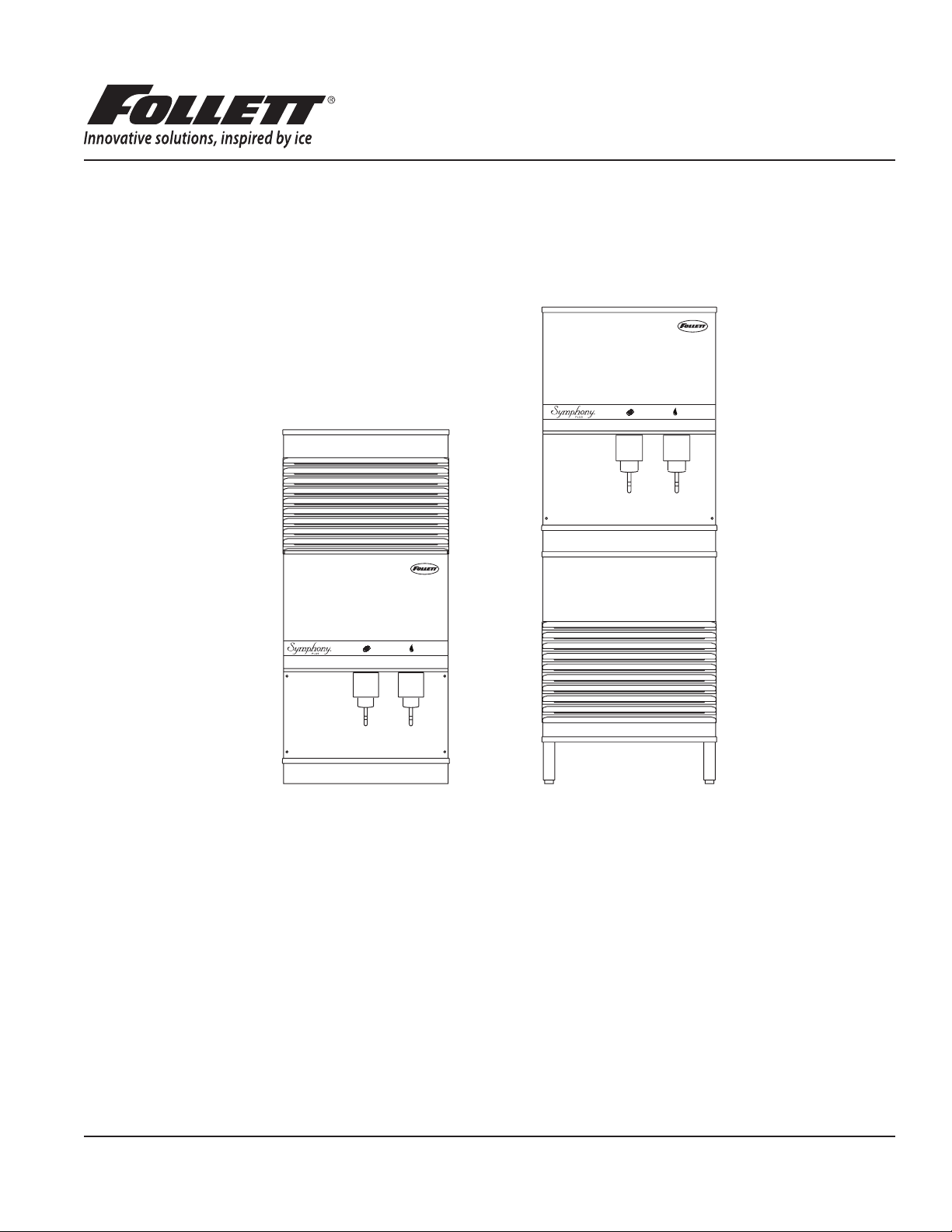
Symphony Plus™ 110 Series
Ice and Water Dispensers
110CT425A/W, 110FB425A/W
Installation Guide
Please visit https://www.follettice.com/technicaldocuments
for the Operation and Service manual for your unit.
Welcome to Follett
Follett equipment enjoys a well-deserved reputation for excellent performance, long-term reliability and outstanding
after-the-sale support. To ensure that this equipment delivers that same degree of service, review this guide carefully
before you begin your installation.
Should you have need technical help, please call our Technical Service group at (877) 612-5086 or (610) 252-7301.
Please have your model number, serial number and complete and detailed explanation of the problem when
contacting Technical Service.
Getting Started
After uncrating and removing all packing material. Inspect the equipment for concealed shipping damage. All freight
is to be inspected upon delivery. If visible signs of damage exist, please refuse delivery or sign your delivery receipt
"damaged." Follett Customer Service must be notied within 48 hours. Wherever possible, please include detailed
photos of the damage with the original packaging so that we may start the freight claim process.
801 Church Lane • Easton, PA 18040, USA
Toll free (877) 612-5086 • +1 (610) 252-7301
www.follettice.com
Installation and Service Videos:
www.follettice.com/servicevideolibrary
01033729R05
CAUTION!
§ Do not tilt unit further than 30° off vertical during uncrating or installation.
§ Dispenser bin area contains mechanical, moving parts. Keep hands and arms clear of this area at all times. If
access to this area is required, power to unit must be disconnected rst.
§ Follett recommends a Follett water lter system be installed in the ice machine inlet water line (standard capacity
#00130229, high capacity #00978957, carbonless high capacity #01050442).
§ Prior to operation clean the dispenser in accordance with instructions found in this manual.
§ Ice is slippery. Be sure counters and oors around dispenser are clean, dry and free of ice.
§ Do not block right side air intake or top air exhaust.
2 110CT425A/W, 110FB425A/W
Specications
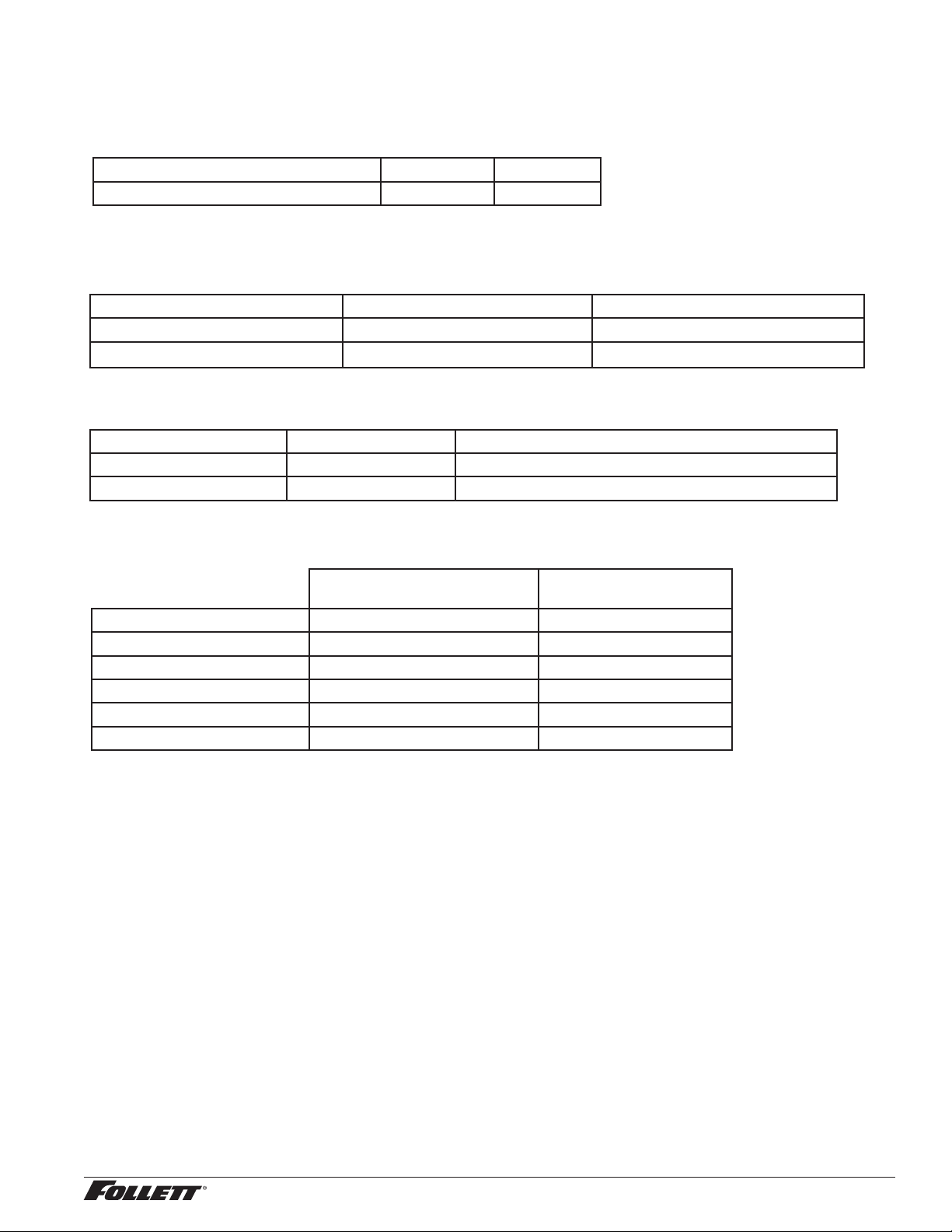
Electrical
§ Freestanding and countertop models (110FB425A/W, 110CT425A/W) require a dedicated circuit.
Total system Max. circuit
Basic electrical: 115 V/60 Hz/1 phase 11.0A 20A
§ Dispensers and ice machines are supplied with 7-foot power cord with NEMA 5-15 hospital-grade plug. Connect
to a dedicated 15A circuit.
Model Electrical connection Circuits required
110FB425A/W cord & plug provided 115/60/1, 15A max. fuse size
110CT425A/W cord & plug provided 115/60/1, 15A max. fuse size
Ambient
Air temp* 100 F/38 C Max. 50 F/10 C Min. (Best performance below 80 F/27 C)
Water temp
†
Water pressure (psi/bar) 70/5 Max. 10/0.7 Min.
*
Ambient air temperature is measured at the air-cooled condenser coil inlet.
†
Ambient water temperature is measured in the ice machine reservoir.
90 F/32 C Max. 45 F/7.2 C Min. (Best performance below 70 F/21 C)
Plumbing
110CT with integral ice
machine
Dispenser drain 3/4" MPT 3/4" MPT
Ice machine drain 3/4 MPT 3/4" MPT
Dispenser water inlet 3/8" FPT 3/8" FPT
Ice machine water inlet 3/8" FPT —
Cond. inlet – w/c only 3/8" FPT 3/8" FPT
Cond. drain – w/c only 3/8" FPT 3/8" FPT
Note: Water shut-off recommended within 10 ft (3 m) of dispenser. Drain to be hard-piped and insulated. Maintain at
least 1/4" per foot (20 mm per 1 m) run of slope.
110FB with ice machine
in base
Ventilation clearances
§ 110CT425A/W: 6" (15.2 cm) required at top.
Note: 6" (15.2 cm) at each side advised for service.
§ 110FB425A/W: 4" (10.2 cm) required at rear .
Note: 12" (30.5 cm) at top advised for service.
Approximate shipping weight
§ 290 lb (132 kg), base stand: 140 lb (64 kg)
110CT425A/W, 110FB425A/W 3

Installation
Before you begin
§ All dispensers must be installed level in both directions to ensure proper operation.
§ All countertop dispensers provide the option of taking utilities out the bottom or back of the dispenser.
See counter cut-out (Fig. 2) for bottom exiting utilities on units with and without drain pans. For installations
where utilities will exit through back of dispenser, refer to back view drawings.
Installing freestanding dispensers
1. Position dispenser in desired location and adjust legs to level in both directions.
2. Connect water supply to 3/8" FPT tting on back of dispenser (Fig. 1).
3. Connect separate drain lines to 3/4" MPT dispenser drain tting, and 3/4" MPT ice machine drain tting
on back of dispenser.
4. Run drain lines to wall or oor drain. If ice machine drain tting is below an intended wall drain, a
condensate pump must be used.
5. If ice machine is a water-cooled unit, connect water-cooled condenser supply line to 3/8" FPT condenser
inlet tting on back of dispenser.
Note: Do not run condenser supply water through ice machine water lter system.
6. Connect condenser drain line to 3/8" FPT condenser outlet tting on back of dispenser.
Important: Do not connect condenser drain line to any other drain lines.
7. Plug dispenser into 15A rated NEMA 5-15 circuit.
8. Remove front cover of base section by removing two screws at bottom corners of cover. Allow cover to
drop approximately 3/8" (5 mm) and pull forward.
9. Turn on water supply and check for leaks.
4 110CT425A/W, 110FB425A/W
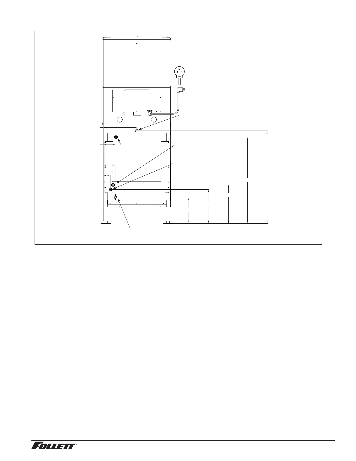
Fig. 1 – Rear connections, freestanding models
access panel
12.25" (31.2 cm)
power cord
NEMA 5-15
3/4" MPT drain
4.75" (11.9 cm)
4.5" (11.4 cm)
3.75" (9.3 cm)
2.75" (6.8 cm)
3/8" FPT
water inlet
3/4" MPT ice machine drain location
3/8" FPT condenser inlet location
(water-cooled only)
3/8" FPT condenser outlet location
(water-cooled only)
31.5" (80 cm)
14" (35.7 cm)
12.38" (31.4 cm)
9.62" (24.4 cm)
33.75" (85.8 cm)
10. Remove top front cover by removing two screws at bottom corners of cover. Lift cover slightly and pull
forward.
11. If dispenser is equipped with SensorSAFE remove protective plastic coating from dispense sensor labels.
12. Turn on dispenser power and bin signal rocker switches. Check dispenser and ice machine operation.
13. Clean ice machine according to instructions in the Cleaning section. Discard ice made during cleaning
process.
14. Turn off ice machine bin signal switch.
15. Remove dispenser hopper lid; clean dispenser according to instructions.
16. Turn ice machine bin signal switch on and replace front covers, securing with screws.
110CT425A/W, 110FB425A/W 5
 Loading...