

Page 1
Common power
Unbalanced load:
kVA
TOTAL
= kVA1 + kVA2 + kVA
3
kVA
1
Red
Red
Red
Black
Black
Black
kVA
2
kVA
3
ø1
ø2
ø3
N
quality factors
affecting transformers
Application Note
Commercial buildings commonly
have a 208/120 V transformer in
a delta-wye configuration to
feed receptacles. Single-phase,
non-linear loads connected to
the receptacles produce triplen
harmonics, which add up in the
neutral. When this neutral current reaches the transformer, it is
reflected into the delta primary
winding where it causes overheating and transformer failures.
Another transformer problem
results from core loss and copper
loss. Transformers are normally
rated for a 60 Hz phase current
load only. Higher frequency harmonic currents cause increased
core loss due to eddy currents
and hysteresis, resulting in more
heating than would occur at the
same 60 Hz current.
Transformers supplying nonlinear loads should be checked
periodically to verify operation
within acceptable limits. Transformers are also critical to the
integrity of the grounding system.
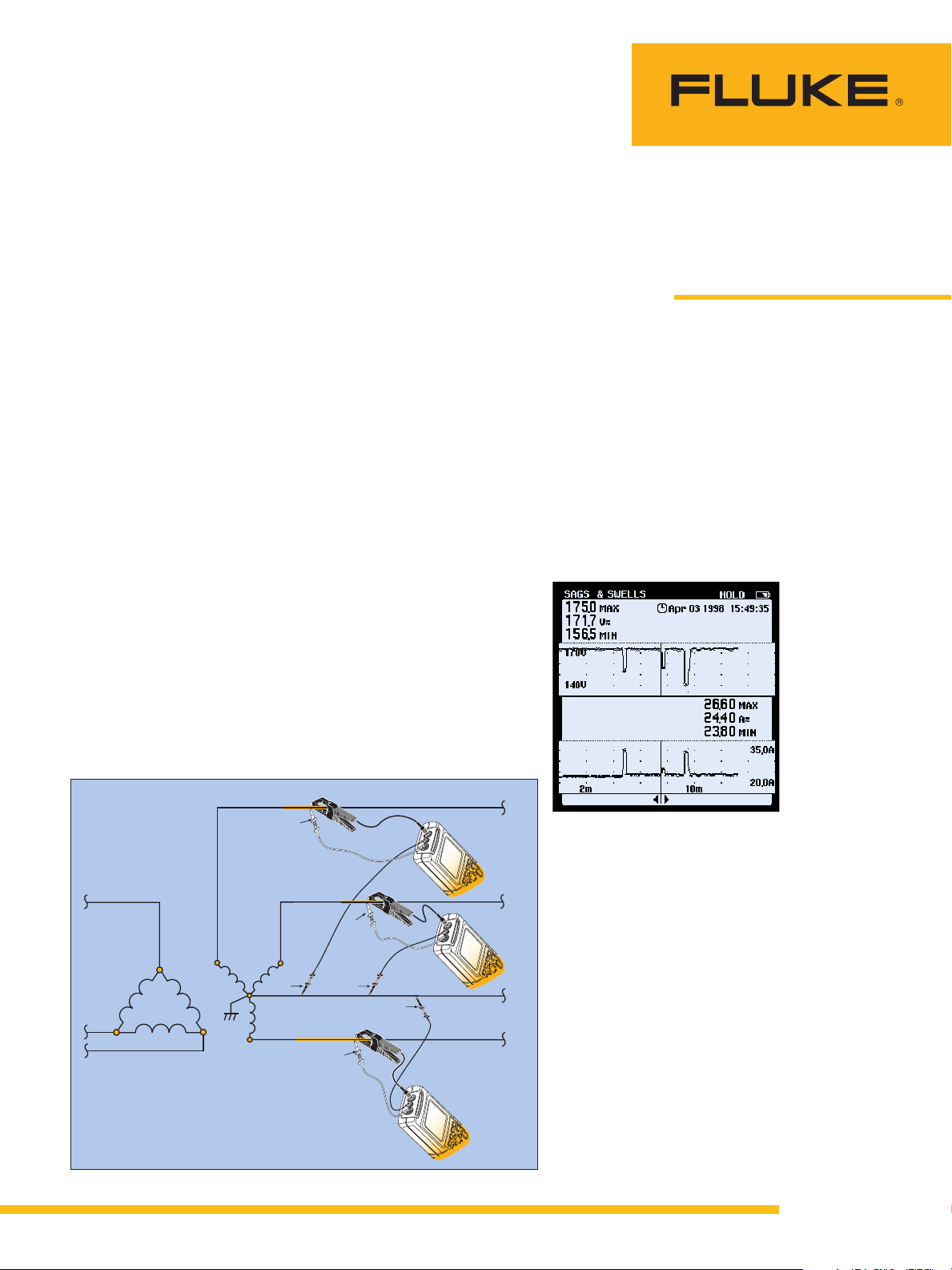
Factors
1. Transformer loading (kVA)
Start by measuring kVA and
determine wether the transformer
load is balanced.
Connect voltage probes on
•
Phase 1 and Neutral and
clamp current probe on same
phase. Repeat for Phase 2 and
3.
Use a single phase power
•
quality analyzer to read kVA of
each phase and sum all three
for total transformer kVA.
Or, connect all four current
•
clamps and all five test leads
for the three phase power
quality analyzer to read kVA
for each phase and the total.
Compare actual load kVA to
•
nameplate kVA rating to determine % loading.
When using a single phase
analyzer on a balanced load, a
single measurement is suffic
ient.
Transformers loaded at less than
50 % are generally safe from
overheating. However, as loads
increase, measurements should
be made periodically. At some
point the transformer may require
derating.
Figure 2. Harmonic spectrum.
2. Harmonic spectrum
The harmonic spectrum of the
secondary (load) current will give
us an idea of the harmonic orders
and amplitudes present:
In a transformer feeding sin
•
-
gle-phase loads, the principal
n is the
er
onc
ill add arith-
ye transformer
y
.
harmonic of c
. The 3rd w
3rd
metically in the neutral and
irculate in the delta primar
c
of a delta-w
The good news is that the
delta-w
rest of the system from the 3rd
(though not the 5th, 7th or
ye tends to isolate the
other non-triplen harmonics).
e 1
Figur
. Measuring transformer load (unbalanc
From the Fluke Digital Library @ www.fluke.com/library
ed) using a single phase power quality analy
The bad new
transformer pa
w
.
zer
ith additional heat
s is that the
ys the pric
.
e
Page 2
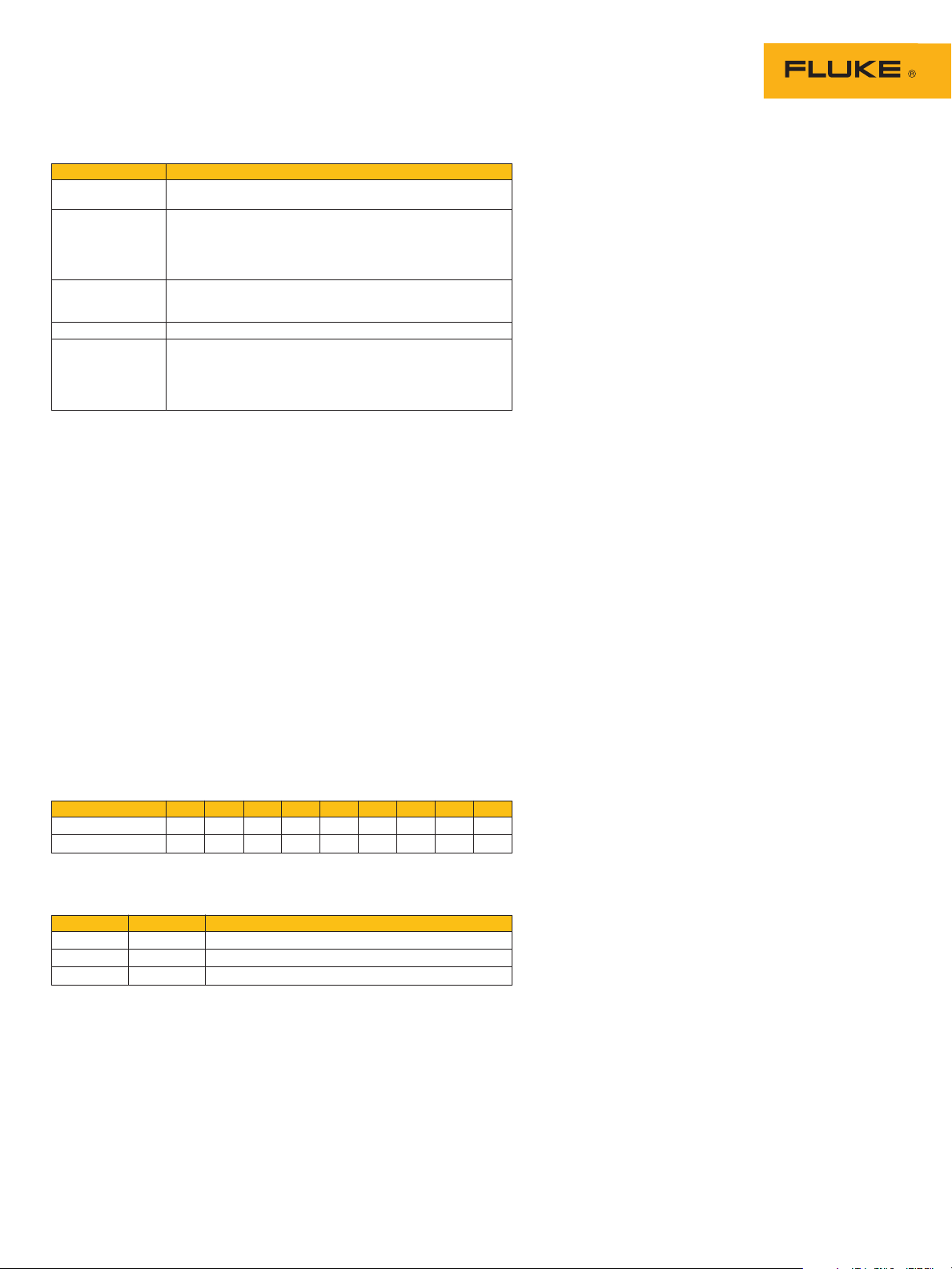
Table 1: Measurements at the distribution transformer
Measurement
. kVA Transformer loading. If loading exceeds 50 %, check for harmonics
1
2. Harmonic
spectrum 3rd harmonic (single-phase loads)
3. THD Harmonic loading within limits:
-factor Heating effect on transformer from harmonic loads
4. K
5. Ground currents
In a transformer feeding three-
•
phase loads which include
drives or UPS systems with 6pulse converters, the 5th and
7th harmonic will tend to predominate. Excessive 5th is of
particular concern because it is
negative sequence. It will tend
to produce counter-torque and
overheating in polyphase
motors.
Harmonic amplitudes normally
•
decrease as the frequency
goes up. If one frequency is
significantly higher in amplitude than lower frequencies,
we can suspect a resonant
Look for
and possible need for derating.
Harmonic orders/amplitudes present:
•
5th, 7th (primarily three-phase loads)
e of higher order harmonics
Resonanc
•
Effectiveness of harmonic trap filters
•
Voltage %THD < 5 %
Current %T
•
•
•
HD < 5-20 % (Table 2)
Objectionable ground currents are not quantified but are
prohibited by the N
eutral-ground bond in place
N
ESG (Electrical Safety Ground) connector to ground electrode
(typically building steel) in place
EC
condition at that frequency. If
such a condition is detected,
be sure to take readings at
capacitor banks to see if the
caps are experiencing overcurrent/overvoltage conditions.
Before-and-after harmonic
•
spectrum measurement is
extremely valuable to determine if harmonic mitigation
techniques, like trap filters,
which are tuned to specific
frequencies, are sized properly
and are working as expected.
Different harmonic frequencies
•
affect equipment in different
ways (see below).
Harmonic Sequences
Name F 2nd 3rd 4th 5th 6th 7th 8th 9th
180 240 300 360 420 480 540
20
Frequenc
Sequence +—0+—0+—0
Rule: If waveforms are symmetrical, even harmonics disappear.
Eff
Sequence Rotation Effects (from skin effect, eddy currents, etc.)
Positive Forward Heating of conductors, circuit breakers, etc.
N
Zero None Heating, + add in neutral of 3-phase, 4-wire system
Harmonics are classified as follows:
1. Order or number: Multiple of fundamental, hence, 3rd is three times the fundamental, or
2.
3. Sequence:
y
ects of Harmonic Sequences
egative
0 Hz
8
1
Odd or even order: Odd harmonics are generated during normal operation of nonlinear
loads. Even harmonics only appear when there is dc in the system. In power circuits, this
only tends to occur when a solid state component(s), such as a diode or SCR, fails in a
onverter c
c
Positive sequence. Main effect is overheating.
•
Negative sequence. Create counter-torque in motors, i.e., will tend to make motors go
•
backwards, thus causing motor overheating. Mainly 5th harmonic.
Zero sequenc
•
Reverse
.
.
ircuit
e. Add in neutral of 3-phase, 4-w
1
0
6
Heating as above + motor problems
ire system
. Mainly 3rd harmonic.
3. Total Harmonic Distortion
Check for THD of both voltage
and current:
For voltage, THD should not
•
exceed 5 %
For current, THD should not
•
exceed 5-20 % (see Odd
Harmonics table)
IEEE 519 sets limits for har-
monics at the PCC (Point of
Common Coupling) between the
utility and customer (EN50160 is
the European standard). IEEE 519
is based on THD measurements
taken at the PCC. Technically, the
PCC is the primary of the utility
supply transformer (although
there are cases where the PCC is
at the secondary if the secondary
feeds a number of customers). In
practice, these measurements are
often made at the secondary of
the customer’s main transformer,
since that is the point most easily
accessible to all parties (and also
since that is generally a Low
Voltage measurement).
Some PQ practitioners have
broadened the concept of PCC to
include points inside the facility,
such as on the feeder system,
where harmonic currents being
generated from one set of loads
could affect another set of loads
by causing significant voltage
distortion. The emphasis is on
improving in-plant PQ, rather
than on simply not affecting utility PQ.
3a. Voltage THD
THD has a long history in the
industry. The underlying concept
is that harmonic currents generated by loads will cause voltage
distortion (E=IZ) as they travel
through the system impedance.
This voltage distortion then
becomes the carrier of harmonics
system-wide: if, for example, the
distorted voltage serves a linear
load like a motor, it will then create harmonic currents in that
linear load. By setting maximum
limits for voltage distortion, we
set limits for the system-wide
impact of harmonics.
2 Fluke Corporation Common power quality factors affecting transformers
Page 3

Table 2: IEEE 519 limits for harmonic currents at the point of
common coupling
CR=Isc/IL <11 11-17 17-23 23-35 >35 TDD
S
<20
20-50
00 10.0 % 4.5 % 4.0 % 1.5 % 0.7 % 12.0 %
50-1
00-1000 12.0 % 5.5 % 5.0 % 2.0 % 1.0 % 15.0 %
1
000 15.0 % 7.0 % 6.0 % 2.5 % 1.4 % 20.0 %
>1
Short circuit ratio (Isc/I
SCR=
Available short circuit current at PCC
Isc =
Maximum demand load current (rms amps)
IL=
TDD = Total demand distortion
Note: IEE E allows these limits to be exceeded for up to one hour per day, while IEC allows
them to be exceeded for up to 5 % of the time.
The concept of
ties,
ILis calculated by a
(information a
Transformer rating could be used and would be the most conservative estimate (i.e., it would
result in the lowest SCR), since it assumes that the transformer would be used at full capacity.
IL, maximum demand load current, is key to using Table 2. For existing facili-
vailable in billing records). For new installations,
Voltage distortion, however,
depends on source impedance,
i.e., on system capacity. It was
quite possible for the first (or second or third) customer to inject
significant harmonic currents into
the system and not cause voltage
THD to exceed 5 %. The entire
responsibility for harmonic mitigation could fall on the last
customers unlucky enough to
push V-THD over 5 %, even if
their particular harmonic load
was relatively small-literally the
straw that broke the camel’s
back.
3b. Current T
To restore some fairness to this
(All percentages are % of IL, maximum demand load current)
Odd Harmonics
4.0 % 2.0 % 1.5 % 0.6 % 0.3 % 5.0 %
7.0 % 3.5 % 2.5 % 1.0 % 0.5 % 8.0 %
)
L
ing the maximum demand current for 12 consecutive months
verag
ILmust b
e estimated.
For equipment manufacturers,
IEC 1000-3-2, published in 1995,
is the applicable standard. It
specifies maximum current levels
out to the 40th harmonic. Its
expected effective date is projected to be early 2001. To certify
for CE, a requirement for the
European market, manufacturers
will have to meet this standard.
This edict will have a major effect
on power supply design.
For the facility, IEEE 519 is the
standard (EN 50160 in Europe).
The limits set in IEEE 519 for
harmonic currents depend on the
D
H
size of the customer relative to the
system capac
ity. (See Table 2.)
situation, standards for maximum
current harmonics were added,
e current harmonics were
sinc
under the control of the local
ility and equipment manufac
fac
turer (rememb
er, harmonic
“loads” act as “generators” of harmonics). This emphasis on the
mitigation of current harmonics at
the load, including the not-too-
Table 3
Inspection of Transf
-
Check for N-G bond. A high impedance N-G bond will cause
Check for g
integrity of connection to building steel these connections, so they should be as low
(exothermic weld). impedance as possible.
Check for tightness of all
conduit connections. will tend to act as a “choke” for higher
rounding c
ormer Ground Explanation
onductor and
distant requirement that the load
generate virtually no harmonics,
has become the prevailing regu-
y philosophy
lator
. It puts the
burden of responsibility on the
Measure for
grounding conductor. always be some ground current due to
ground currents on the Ideally there should be none, but there will
local site and on the equipment
manufacturers
.
The SCR (Short Circuit Ratio) is
a measure of the electrical size of
the customer in relation to the
utility source. The smaller the
customer (higher SCR), the less
the potential impact on the utility
sourc
e and the more generous
the harmonic limits. The larger
the customer (smaller SCR), the
more stringent the limits on harmonic currents.
3c. TDD and THD
TDD (Total Demand Distortion) is
the ratio of the current harmonics
to the
maximum load (IL). It dif-
fers from THD in that THD is the
ratio of harmonics to the
taneous
load. Why TDD instead
instan-
of THD? Suppose you were running a light load (using a small
fraction of system capacity), but
those loads were nonlinear. THD
would be relatively high, but the
harmonic currents actually being
generated would be low, and the
effect on the supply system
would in fact be negligible. So
who cares? TDD acknowledges
this, and allows harmonic load to
be referenced to the maximum
load: if harmonic load is high at
maximum load, then we have to
watch out for the effect on the
supply source. So where does
that leave current THD as a useful
measurement.
The closer the current THD reading(s) is taken to
conditions of maximum load, the
D.
D
closer it appr
voltage fluctuation.
ault currents will return to the source via
F
onduit is not itself g
If the c
frequencies and limit fault current
(remember that fault currents are not just
at 60 Hz but have high-f components).
normal operation or leakage of protective
components (MOVs, etc.) connected from
phase or neutral to ground. However,
anything above an amp should be cause
for suspic
but experienc
a feel for possible problems).
oximate
ion (there is no hard and fast rule,
ed PQ troubleshooters develop
s T
rounded, it
3 Fluke Corporation Common power quality factors affecting transformers
Page 4

A final word on measuring
480 V
208 Y/120 V
Neutral
Grounding electrode nearby,
preferably structural metal
THD: the one place not to apply
the specs is at the individual harmonic-generating load. This will
always be a worst-case distortion
and a misleading reading. This is
b
ecause as harmonics travel
upstream, a certain amount of
cancellation takes place (due to
phase relationships which, for
practical purposes, are unpredictable). Measure at a PCC, or at
the source transformer.
4. K-factor
K-factor is a specific measure of
the heating effect of harmonics in
general and on transformers in
particular. It differs from the THD
calculation in that it emphasizes
the frequency as well as the
amplitude of the harmonic order.
This is because heating effects
increase as the square of the frequency.
A K-4 reading would mean
that the stray loss heating effects
are four times normal. A standard
transformer is, in effect, a K-1
transformer. As with THD, it is
misleading to make a K-factor
reading at the load or receptacle
because there will be a certain
amount of upstream cancellation;
transformer K-factor is what
counts. Once the K-factor is
determined, choose the next
higher trade size. K-factor rated
transformers are available in
standard trade sizes of K-4, K-13,
K-20, K-30, etc. K-13 is a common rating for a transformer
supplying office loads. The higher
ratings tend to be packaged into
PDUs (Power Distribution Units)
which are spec
ially designed to
supply computer and other PQsensitive installations.
5. Ground currents
Two prime suspects for excessive
ground current are illegal N-G
bonds (in subpanels, receptacles
or even in equipment) and socalled isolated ground rods:
Subpanel N-G bonds create a
•
parallel path for normal return
current to return via the
grounding conductor. If the
neutral ever becomes open, the
equipment safety ground
becomes the only return path;
if this return path is high
impedance, dangerous voltages
could develop.
Separate isolated ground rods
•
almost always create two
ground references at different
potentials, which in turn
causes a “ground loop” current
to circulate in an attempt to
equalize those potentials. A
safety and equipment hazard is
also created: in the case of
lightning strikes, surge currents
travelling to ground at different
earth potentials will create
hazardous potential differences.
Transformer grounding
The proper grounding of the
transformer is critical. (Table 3.3.)
NEC Article 250 in general and
250-26 in particular address the
grounding requirements of the
SDS.
A ground reference is estab-
•
lished by a grounding
connection, typically to building steel (which, in turn, is
required to be bonded to all
cold water pipe, as well as
any and all earth grounding
electrodes). Bonding should be
by exothermic weld, not
clamps that can loosen over
time. The “grounding electrode
conductor” itself should have
as low a high-frequency
impedance as possible (not
least because fault current has
high frequency components).
Wide, flat conductors are preferred to round ones because
they have less inductive reactance at higher frequencies.
For the same reason, the distance between the “grounding
electrode conductor connection
to the system” (i.e., N-G bond
at the transformer) and the
grounding electrode (building
steel) should be as short as
possible: in the words of the
Code, “as near as practicable
to and preferably in the same
...”
area
The neutral and ground should
•
be connected at a point on the
transformer neutral bus
.
Although permitted, it is not
advisable to make the N-G
ond at the main panel, in
b
order to maintain the segregation of normal return currents
and any g
round currents
. This
point at the transformer is the
only point on the system
G should be bonded.
where N
-
Figure 3. Transformer grounding.
4 Fluke Corporation Common power quality factors affecting transformers
Page 5

Solutions
There are a number of solutions
for transformer-related PQ
problems:
Install additional distribution
•
transformers (Separately
Derived Systems)
Derate transformers
•
Install K-rated transformers
•
Used forced air cooling
•
1. Separately Derived System
(SDS)
The distribution transformer is
the supply for a Separately
Derived System (SDS), a term
which is defined in the NEC
(Article 100). The key idea is that
the secondary of this transformer
is the new source of power for all
its downstream loads: this is a
powerful concept in developing a
PQ distribution system. The SDS
accomplishes several important
objectives, all beneficial for PQ:
It establishes a new voltage
•
reference
taps which allow the secondary voltage to be stepped up
or down to compensate for
any voltage drop on the feeders.
It lowers source impedance by
•
decreasing, sometimes drastically, the distance between
the load and the source. The
potential for voltage disturbances, notably sags, is
minimized.
It achieves isolation. Since
•
there is no electrical connection, only magnetic coupling,
between the primary and secondary, the SDS isolates its
loads from the rest of the electrical system. To extend this
isolation to high frequency disturbances, specially
constructed “isolation transformers” provide a shield
between the primary and secondary to shunt RF (radio
frequency) noise to ground.
Otherwise, the capacitive coupling between primary and
secondary would tend to pass
these high-frequency signals
right through.
. Transformers have
A new ground reference is
•
established
tion of the SDS is that it “has
no direct electrical connection,
including a solidly connected
grounded circuit conductor, to
supply conductors originating
in another system.” (NEC 100)
The opportunity exists to segregate the subsystem served
by the SDS from ground loops
and ground noise upstream
from the SDS, and vice versa.
rated transformers
2. K-
Figure 4. Typical K-factor in commercial
building.
Harmonics cause heating in
transformers, at a greater rate
than the equivalent fundamental
currents would
of their higher frequency. There
are three heating effects in transformers that increase w
frequency:
Hysteresis. When steel is
•
mag
all line up, so that the North
poles all point one way, the
South poles the other
poles switch with the polarity
of the applied current. The
higher the frequenc
often the switching occurs,
and, in a process analogous to
the effects of friction, heat
losses increase.
Eddy currents. Alternating
•
mag
whirlpools of current that create heat loss. This effect
increases as a square of the
. Part of the defini-
. This is because
ith
netized, mag
netic fields create localized
netic dipoles
. These
y, the more
frequency. For example, a 3rd
harmonic current will have
nine times the heating effect
as the same current at the fundamental.
Skin effect. As frequency
•
increases, electrons migrate to
the outer surface of the conductor. More electrons are
using less space, so the effective impedance of the
onductor has increased; at
c
the higher frequency, the conductor behaves as if it were a
lower gauge, lower ampac
higher impedanc
The industry has responded
with two general solutions to the
effects of harmonics on transformers: install a K-factor rated
transformer or derate a standard
transformer. Let’s look at pros
and cons of the K-factor approach
first. K-factor is a calculation
based on the rms value, %HD
(harmonic distortion) of the harmonic currents, and the square of
the harmonic order (number). It is
not necessary to actually perform
the calculation because a harmonic analyzer will do that for
you. The important thing to
understand is that the harmonic
e w
ity,
ire.
5 Fluke Corporation Common power quality factors affecting transformers
Page 6

order is squared in the equation
0
0
20
40
60
80
100
20 40 60 80 100
Transformer Capacity (%)
After Derating for
Electronic Load
Switched-Mode Power Supply Load (% of Overall Load)
and that is precisely where the
high- frequency heating effects,
like eddy current losses, are
taken into account.
K-rated transformers are
desig
ned to minimize and accommodate the heating effects of
harmonics. K-rated transformers
do not eliminate harmonics
(unless additional elements like
filters are added). They accommodate harmonics with
techniques such as the use of a
number of smaller, parallel windings instead of a single large
inding: this gives more skin for
w
the electrons to travel on. The
primary delta winding is up-sized
to tolerate the c
irculating third
harmonic currents without overheating. The neutral on the
secondary is also up-sized for
third harmonics (typically sized at
twice the phase ampacity).
Application issues with
K-factor transformers
K-rated transformers have been
widely applied, but there are certain issues with them. Many
consultants do not see the need
for using transformers with a rating higher than K-13 although
K-20 and higher might be supplied as part of an integrated
Power Distribution Unit (PDU).
Also, early applications sometimes overlooked the fact that
K-rated transformers necessarily
have a lower internal impedance.
Whereas a standard transformer
has an impedanc
5-6 % range, K-rated transformers can go as low as 2-3 %
(lower as the K
In retrofit situations, where a
standard transformer is being
ed by a K
replac
of equivalent kVA, this may
require new short circuit calculations and re-sizing of the
secondary overcurrent protective
devices.
6 Fluke Corporation Common power quality factors affecting transformers
e typically in the
-rating increases).
-rated transformer
3. Derating standard
transformers
Some facilities managers use a
50 % derating as a rule-of-thumb
for their transformers serving
single-phase, predominantly
nonlinear loads. This means that
a 150 kVA transformer would
only supply 75 kVA of load. The
derating curve, taken from IEEE
1100-1992 (Emerald Book),
shows that a transformer with
60 % of its loads consisting of
SMPS (switched-mode power
supplies), which is certainly
possible in a commercial office
building, should in fact be
derated by 50 %.
The following is an accepted
method for calculating transformer derating for single-phase
loads only. It is based on the very
reasonable assumption that in
single-phase circuits, the third
harmonic will predominate and
cause the distorted current waveform to look predictably peaked.
Use a
true-rms meter to make
these current measurements:
1. Measure rms and peak current
of each secondary phase.
(Peak refers to the instanta-
neous peak, not to the inrush
or “peak load” rms current).
2. Find the arithmetic average of
the three rms readings and the
three peak currents and use
this average in step 3 (if the
load is essentially balanc
this step is not nec
3. Calculate Xformer Harmonic
Derating Factor:
xHDF = (1.414 * IRMS) / IPEAK
4. Or, since the ratio of
Peak/RMS is defined as Crest
Factor, this equation can be
ritten as:
rew
DF = 1.414 / CF
xH
If your test instrument has the
capability, measure the CF of
each phase directly. If the load
is unbalanced, find the aver-
age of the three phases and
use the average in the above
formula.
Since a sine wave current
waveform has a CF=1.414, it will
ve an xH
ha
DF=1; there will be
no derating. The more the 3rd
harmonic, the higher the peak,
ed,
essary).
Figure 5. Transformer derating curve (IEEE 1100-1992)
the higher the CF. If the CF were
2.0, then the xH
DF=1.414 / 2
=.71. A CF=3 gives us an xHDF
=.47. A wave with CF=3 is about
as badly distorted a current
waveform as you can expect to
see on a single-phase distribution
transformer.
Caution: This method does not apply to
transformers feeding three-phase loads,
where harmonics other than the third tend to
predominate and CF is not useful as a simple
predictor of the amount of distortion. A calculation for three-phase loads is available in
ANSI /IEEE C57.110. However, there is some
controversy about this calculation since it
may underestimate the mechanical resonant
vibrations that harmonics can cause, and that
accelerate transformer wear above and
beyond the effects of heat alone.
4. Forced air cooling
If heat is the problem, cooling is
the solution. Break out the fan,
turn it on the transformer and use
forced air cooling. Some experi-
ed hands fig
enc
20-30 % on the up side. In any
case, it can only help.
ure that’s worth
eping your world
Fluke. K
e
up and running.
Fluke Corporation
O Box 9
P
Fluke Europe B.V.
PO Box 1186, 5602 BD
Eindhoven, The N
For more information call:
In the U.S.A. (800) 443-5853 or
ax (425) 446-5
F
In Europe/
Fax (31 40) 2 675 222
In Canada (800) 36-FLUKE or
ax (9
F
From other countries +1 (425) 446-5500 or
Fax +1 (425) 446-5116
Web access: http://www.fluke.com
©2004 Fluke Corporation
Printed in U.S.A. 10/2004 2403202 A-US-N Rev A
0
05) 89
9
M
0, Everett, W
East/
-
0-6866
A USA 98206
etherlands
6
1
1
Africa (3
. All rights reserved.
1 40) 2 6
5 200 or
7
 Loading...