


®
Fluke 434/435
Three Phase Power Quality Analyzer
Users Manual
EN
April 2006, rev. 3, Dec. 2008
© 2006, 2007, 2008 Fluke Corporation, All rights reserved. Printed in The Netherlands All product names are trademarks of their respective companies.
Table of Contents
Chapter |
Title |
Page |
General Aspects................................................................................................. |
|
1-1 |
Introduction.......................................................................................................... |
|
1-1 |
Limited Warranty & Limitation of Liability........................................................ |
1-2 |
|
Declaration of Conformity................................................................................... |
|
1-3 |
Shipment Note ..................................................................................................... |
|
1-4 |
Contacting a Service Center................................................................................. |
|
1-5 |
Safety Information: Read First............................................................................. |
|
1-5 |
About This Manual ............................................................................................. |
|
2-1 |
Introduction.......................................................................................................... |
|
2-1 |
Users Manual Contents........................................................................................ |
|
2-1 |
Features Of Fluke 434/435................................................................................. |
|
3-1 |
Introduction.......................................................................................................... |
|
3-1 |
General Measurements ........................................................................................ |
|
3-1 |
Measuring modes to investigate details ............................................................... |
3-2 |
|
Basic Operations and Menu Navigation .......................................................... |
4-1 |
|
Introduction.......................................................................................................... |
|
4-1 |
Tilt Stand and Hang Strap.................................................................................... |
|
4-1 |
Powering the Analyzer......................................................................................... |
|
4-2 |
Display Brightness............................................................................................... |
|
4-3 |
Locking the keyboard .......................................................................................... |
|
4-3 |
Menu Navigation ................................................................................................. |
|
4-3 |
Display Contrast .................................................................................................. |
|
4-4 |
Reset to Factory Defaults..................................................................................... |
|
4-4 |
Display Information............................................................................................ |
|
5-1 |
Introduction.......................................................................................................... |
|
5-1 |
Phase Colors ........................................................................................................ |
|
5-2 |
Screen Types........................................................................................................ |
|
5-2 |
Screen information common for all screen types................................................. |
5-3 |
|
i

Fluke 434/435
Users Manual
Input Connections.............................................................................................. |
6-1 |
Introduction.......................................................................................................... |
6-1 |
Input Connections ................................................................................................ |
6-1 |
Scope Waveform and Phasor ........................................................................... |
7-1 |
Introduction.......................................................................................................... |
7-1 |
Scope Waveform.................................................................................................. |
7-1 |
Scope Phasor........................................................................................................ |
7-2 |
Tips and Hints...................................................................................................... |
7-3 |
Volts/Amps/Hertz ............................................................................................... |
8-1 |
Introduction.......................................................................................................... |
8-1 |
Meter screen......................................................................................................... |
8-1 |
Trend ................................................................................................................ |
8-2 |
Tips and Hints...................................................................................................... |
8-3 |
Dips & Swells...................................................................................................... |
9-1 |
Introduction.......................................................................................................... |
9-1 |
Trend ................................................................................................................ |
9-3 |
Events Tables....................................................................................................... |
9-4 |
Tips and Hints...................................................................................................... |
9-5 |
Harmonics........................................................................................................... |
10-1 |
Introduction.......................................................................................................... |
10-1 |
Bar Graph Screen................................................................................................. |
10-1 |
Meter screen......................................................................................................... |
10-3 |
Trend ................................................................................................................ |
10-3 |
Tips and Hints...................................................................................................... |
10-4 |
Power & Energy.................................................................................................. |
11-1 |
Introduction.......................................................................................................... |
11-1 |
Meter screen......................................................................................................... |
11-1 |
Trend ................................................................................................................ |
11-4 |
Tips and Hints...................................................................................................... |
11-6 |
Flicker ................................................................................................................. |
12-1 |
Introduction.......................................................................................................... |
12-1 |
Meter screen......................................................................................................... |
12-1 |
Trend ................................................................................................................ |
12-3 |
Tips and Hints...................................................................................................... |
12-4 |
Unbalance ........................................................................................................... |
13-1 |
Introduction.......................................................................................................... |
13-1 |
Meter screen......................................................................................................... |
13-1 |
Trend ................................................................................................................ |
13-2 |
Phasor ................................................................................................................ |
13-3 |
Tips and Hints...................................................................................................... |
13-3 |
ii
|
Contents (continued) |
Transients ........................................................................................................... |
14-1 |
Introduction.......................................................................................................... |
14-1 |
Waveform Display............................................................................................... |
14-1 |
Tips and Hints...................................................................................................... |
14-3 |
Inrush ................................................................................................................. |
15-1 |
Introduction.......................................................................................................... |
15-1 |
Inrush Trend Display ........................................................................................... |
15-1 |
Tips and Hints...................................................................................................... |
15-3 |
Mains Signaling.................................................................................................. |
16-1 |
Introduction.......................................................................................................... |
16-1 |
Trend 16-1 |
|
Events Table ........................................................................................................ |
16-3 |
Tips and Hints...................................................................................................... |
16-4 |
Logger ................................................................................................................. |
17-1 |
Introduction.......................................................................................................... |
17-1 |
Start Menu............................................................................................................ |
17-1 |
Trend ................................................................................................................ |
17-5 |
Meter screen......................................................................................................... |
17-6 |
Events ................................................................................................................ |
17-6 |
Power Quality Monitoring.................................................................................. |
18-1 |
Introduction.......................................................................................................... |
18-1 |
Power Quality Main Screen ................................................................................. |
18-4 |
Events Table ........................................................................................................ |
18-5 |
Trend Display ...................................................................................................... |
18-7 |
Bar Graph Screen................................................................................................. |
18-8 |
Cursor and Zoom ............................................................................................... |
19-1 |
Introduction.......................................................................................................... |
19-1 |
Cursor on Waveform Displays............................................................................. |
19-1 |
Cursor on Trend Displays .................................................................................... |
19-2 |
From Events Table to Trend Display with Cursor On ......................................... |
19-3 |
Cursor on Bar graph Displays.............................................................................. |
19-4 |
Setting up the Analyzer ..................................................................................... |
20-1 |
Introduction.......................................................................................................... |
20-1 |
General Settings................................................................................................... |
20-3 |
FUNCTION PREFerences................................................................................... |
20-7 |
USER PREFerences............................................................................................. |
20-11 |
Limits Adjustments.............................................................................................. |
20-13 |
Using Memory, Printer, and PC ........................................................................ |
21-1 |
Introduction.......................................................................................................... |
21-1 |
Using memory...................................................................................................... |
21-1 |
Use of Printer and PC .......................................................................................... |
21-3 |
iii

Fluke 434/435
Users Manual
Tips and Maintenance........................................................................................ |
22-1 |
Introduction.......................................................................................................... |
22-1 |
Cleaning the Analyzer and its Accessories.......................................................... |
22-1 |
Storing the Analyzer ............................................................................................ |
22-1 |
Keeping the Battery in Good Condition .............................................................. |
22-1 |
Installation of Options in Fluke 434 .................................................................... |
22-1 |
Parts and Accessories........................................................................................... |
22-2 |
Troubleshooting ................................................................................................... |
22-3 |
Specifications..................................................................................................... |
23-1 |
Introduction.......................................................................................................... |
23-1 |
Electrical Measurements...................................................................................... |
23-2 |
iv
Chapter 1
General Aspects
Introduction
This chapter informs you about a number of general and important aspects concerning the Fluke 434/435 Three Phase Power Quality Analyzer (hereafter referred to as ‘Analyzer’).
This concerns:
•Warranty and Liability Conditions.
•Declaration of Conformity.
•Shipment Note: Survey of items that should be included in your Analyzer Kit.
•Contacting a Service Center.
•Safety Information: Read First!
1-1

Fluke 434/435
Users Manual
Limited Warranty & Limitation of Liability
Each Fluke product is warranted to be free from defects in material and workmanship under normal use and service. The warranty period is three years for the Analyzer and one year for its accessories. The warranty period begins on the date of shipment. Parts, product repairs and services are warranted for 90 days. This warranty extends only to the original buyer or end-user customer of a Fluke authorized reseller, and does not apply to fuses, disposable batteries or to any product which, in Fluke's opinion, has been misused, altered, neglected or damaged by accident or abnormal conditions of operation or handling. Fluke warrants that software will operate substantially in accordance with its functional specifications for 90 days and that it has been properly recorded on nondefective media. Fluke does not warrant that software will be error free or operate without interruption.
Fluke authorized resellers shall extend this warranty on new and unused products to enduser customers only but have no authority to extend a greater or different warranty on behalf of Fluke. Warranty support is available if product is purchased through a Fluke authorized sales outlet or Buyer has paid the applicable international price. Fluke reserves the right to invoice Buyer for importation costs of repair/replacement parts when product purchased in one country is submitted for repair in another country.
Fluke's warranty obligation is limited, at Fluke's option, to refund of the purchase price, free of charge repair, or replacement of a defective product which is returned to a Fluke authorized service center within the warranty period.
To obtain warranty service, contact your nearest Fluke authorized service center or send the product, with a description of the difficulty, postage and insurance prepaid (FOB Destination), to the nearest Fluke authorized service center. Fluke assumes no risk for damage in transit. Following warranty repair, the product will be returned to Buyer, transportation prepaid (FOB Destination). If Fluke determines that the failure was caused by misuse, alteration, accident or abnormal condition of operation or handling, Fluke will provide an estimate of repair costs and obtain authorization before commencing the work. Following repair, the product will be returned to the Buyer transportation prepaid and the Buyer will be billed for the repair and return transportation charges (FOB Shipping Point).
THIS WARRANTY IS BUYER'S SOLE AND EXCLUSIVE REMEDY AND IS IN LIEU OF ALL OTHER WARRANTIES, EXPRESS OR IMPLIED, INCLUDING BUT NOT LIMITED TO ANY IMPLIED WARRANTY OF MERCHANTABILITY OR FITNESS FOR A PARTICULAR PURPOSE. FLUKE SHALL NOT BE LIABLE FOR ANY SPECIAL, INDIRECT, INCIDENTAL OR CONSEQUENTIAL DAMAGES OR LOSSES, INCLUDING LOSS OF DATA, WHETHER ARISING FROM BREACH OF WARRANTY OR BASED ON CONTRACT, TORT, RELIANCE OR ANY OTHER THEORY.
Since some countries or states do not allow limitation of the term of an implied warranty, or exclusion or limitation of incidental or consequential damages, the limitations and exclusions of this warranty may not apply to every buyer. If any provision of this Warranty is held invalid or unenforceable by a court of competent jurisdiction, such holding will not affect the validity or enforceability of any other provision.
Fluke Corporation, P.O. Box 9090, Everett, WA 98206-9090 USA, or Fluke Industrial B.V., P.O. Box 90, 7600 AB, Almelo, The Netherlands
1-2

General Aspects 1
Declaration of Conformity
Declaration of Conformity
Declaration of Conformity
for
Fluke 434/435
Three Phase Power Quality Analyzers
Manufacturer
Fluke Industrial B.V.
Lelyweg 14
7602 EA Almelo
The Netherlands
Statement of Conformity
Based on test results using appropriate standards, the product is in conformity with
Electromagnetic Compatibility Directive 2004/108/EC Low Voltage Directive 2006/95/EC
Sample tests
Standards used:
EN 61010-1-2001
Safety Requirements for Electrical Equipment for Measurement, Control, and Laboratory Use
EN 61326-1-2006
Electrical equipment for Measurement Control and Laboratory use
EMC requirements
The tests have been performed in a typical configuration.
This Conformity is indicated by the symbol 

 , i.e. “Conformité Européenne”.
1-3

Fluke 434/435
Users Manual
Shipment Note
The following items are included in your Analyzer Kit:
Note:
When new, the Analyzer’s rechargeable NiMH battery is not charged. Refer to Chapter 4 – Powering the Analyzer.
Figure 1-1. Contents of Analyzer Kit
1-4
General Aspects 1
Contacting a Service Center
# |
Description |
|
|
|
|
1 |
Power Quality Analyzer |
|
|
|
|
2 |
Decal Set for Input Sockets |
|
|
|
|
3 |
Hang Strap |
|
|
|
|
4 |
Alligator Clips. Set of 5 |
|
|
|
|
5 |
Test Leads, 2.5 m. Set of 5 |
|
|
|
|
6 |
Battery Charger / Power Adapter |
|
|
|
|
7 |
Line Plug Adapter (country dependent) |
|
|
|
|
8 |
Getting Started Manual + CD ROM with Users Manual and Getting Started Manual (multi- |
|
|
language) |
|
|
|
|
9 |
Optical Cable for USB |
|
|
|
|
|
Fluke 434: |
Fluke 435: |
|
|
|
10 |
CD ROM with FlukeView® Software for |
CD ROM with FlukeView® Software for |
|
Windows® |
Windows® + Power Log Software for Windows® |
11 |
AC Current Clamps 400 A (1 mV/A) and 40 A |
Flexible AC Current Clamps 3000 A. Set of 4. |
|
(10 mV/A) switcheable. Set of 4 pcs. i400s. |
Model i430flex-4pk. |
|
|
|
12 |
Hard Case C430. |
Heavy Duty Trolley Style Case C435 |
|
|
|
Contacting a Service Center
To locate a Fluke authorized service center, visit us on the World Wide Web at: www.fluke.com or call Fluke using any of the phone numbers listed below:
+1-888-993-5853 in the U.S. and Canada +31-40-2675200 in Europe +1-425-446-5500 from other countries
Safety Information: Read First
The Fluke 434/435 Three Phase Power Quality Analyzer complies with: IEC/EN61010-1-2001,
CAN/CSA C22.2 No 61010-1-04 (including cCSAus approval), UL std No 61010-1,
Safety Requirements for Electrical Equipment for Measurement, Control and Laboratory Use, Part 1: General requirements, Rated: 600V CAT IV 1000V CAT III Pollution Degree 2.
Use the Analyzer and its accessories only as specified in the Users Manual. Otherwise, the protection provided by the Analyzer and its accessories might be impaired.
A Warning identifies conditions and actions that pose hazard(s) to the user. A Caution identifies conditions and actions that may damage the Analyzer.
The following international symbols are used on the Analyzer and in this manual:
1-5
Fluke 434/435
Users Manual
|
See explanation in |
|
|
|
|
|
|
|
|
Direct Current |
|
Safety Approval |
|
|
|
|
|
|
|||||||
|
manual |
|
|
|
|
|
|
|
|
|
|
|
|
Earth |
|
|
|
|
|
|
|
Double Insulation |
|
Conformité Européenne |
|
|
|
|
|
|
|
|
|
|
|
(Protection Class) |
|
|
|
Alternating Current |
|
|
|
|
|
|
|
Recycling information |
|
Disposal information |
|
|
|
|
|
|
|
|
|
|
|
|
|
|
Do not apply around or remove from hazardous live conductors.
Do no dispose of this product as unsorted municipal waste. Go to Fluke’s website for recycling information
 Warning
To avoid electrical shock or fire:
•Review the entire manual before use of the Analyzer and its accessories.
•Avoid working alone.
•Do not operate the Analyzer around explosive gas or vapor.
•Use only insulated current probes, test leads and adapters as supplied with the Analyzer, or indicated as suitable for the Fluke 434/435 Analyzer.
•Before use, inspect the Analyzer, voltage probes, test leads and accessories for mechanical damage and replace when damaged. Look for cracks or missing plastic. Pay special attention to the insulation surrounding the connectors.
•Remove all probes, test leads and accessories that are not in use.
•Always connect the Battery Charger / Power Adapter first to the AC outlet before connecting it to the Analyzer.
•Use the ground input only to ground the Analyzer and do not apply any voltage.
•Do not apply input voltages above the rating of the instrument.
•Do not apply voltages in excess of the marked ratings of the voltage probes or current clamps.
•Take special care during fitting and removal of the flexible current probe: de-energize the installation under test or wear suitable protective clothing.
•Do not use exposed metal BNC or banana plug connectors.
•Do not insert metal objects into connectors.
•Use only the power supply, Model BC430 (Battery Charger / Power Adapter).
•Before use check that the selected/indicated voltage range on the BC430 matches the local line power voltage and frequency (refer to figure below). If necessary set the slider switch of the BC430 to the correct voltage.
1-6

General Aspects 1
Safety Information: Read First
•For the BC430 use only AC line plug adapters or AC line cords that comply with local safety regulations.
Slider switch on BC430 Battery Charger / Power Adapter to select line power voltage:
|
|
|
|
115V |
|
230V |
|
|
|
|
|
|
|
|
|
|
|
|
|
||
|
|
|
|
|
|
|
|
|
|
|
|
|
|
|
|
|
|
|
|
|
|
 Max. Input Voltage at Voltage Banana Inputs to Ground:
Input A (L1), B (L2), C (L3), N to Ground: 1000 V Cat III, 600 V Cat IV.
 Max. Voltage at Current BNC Inputs (See marking):
Input A (L1), B (L2), C (L3), N to Ground: 42 V peak.
Voltage ratings are given as “working voltage”. They should be read as V ac rms (50-60 Hz) for AC sinewave applications and as V dc for DC applications.
Measurement Category IV refers to the overhead or underground utility service of an installation. Cat III refers to distribution level and fixed installation circuits inside a building.
If Safety Features are Impaired
If the Analyzer is used in a manner not specified by the manufacturer, the protection provided by the Analyzer may be impaired.
Before use, inspect the test leads for mechanical damage and replace damaged test leads!
If the Analyzer or its accessories appear to be impaired or not functioning properly, do not use it and send it in for repair.
Note
To accommodate connection to various line power sockets, the BC430 Battery Charger / Power Adapter is equipped with a male plug that must be connected to a line plug adapter appropriate for local use. Since the Charger is isolated, you can use line plug adapters with or without a protective ground terminal.
The 230 V rating of the BC430 is not for use in North America. A line plug adapter complying with the applicable National Requirements may be provided to alter the blade configurations for a specific country.
1-7

Fluke 434/435
Users Manual
1-8
Chapter 2
About This Manual
Introduction
This Users Manual gives full and comprehensive information on how to use the Fluke 434 and 435 Three Phase Power Quality Analyzers effectively and in a safe manner. Read it carefully to learn about safe use of the Analyzer and its accessories and to take full advantage of all measuring modes.
The Analyzer is also supplied with a printed Getting Started Guide which provides basic information and can be used as a quick reference.
Users Manual Contents
•Introduction: Title, Table of Contents.
•Chapter 1. General Aspects: Warranty and Liability, Declaration of Conformity, Shipment Note, Contacting a Service Center, Safety information.
•Chapter 2. Overview of manual contents.
•Chapter 3. Summary of measuring modes and how to use them in a logical order.
•Chapter 4. Basic operations: Tilt Stand and Hang Strap, Powering, Display adjustment, Keyboard Locking, Reset, Menu Navigation.
•Chapter 5. Display information: Screen types, General Screen Information, Screen Symbols.
•Chapter 6. Input Connections: Use of voltage and current probes.
•Chapter 7 ... 18. Explanation of measuring functions with tips & hints:
-Scope Waveform & Phasor (7),
-Volts/Amps/Hertz (8),
-Dips & Swells (9),
-Harmonics (10),
-Power & Energy (11),
-Flicker (12),
-Unbalance (13),
-Transients (14),
-Inrush Currents (15),
-Mains Signaling (16)
2-1

Fluke 434/435
Users Manual
-Logger (17)
-Power Quality Monitoring (18).
•Chapter 19. Cursor and Zoom: how to investigate measurement details.
•Chapter 20. Setting up the Analyzer: a comprehensive explanation of adjustments to customize measurements.
•Chapter 21. Using Memory, printer and PC: how to save, recall and delete screenshots and data formats. How to make hard copies of measurement results and setup of communication with PC.
•Chapter 22. Tips and Maintenance: Cleaning, Storage, Batteries, Replaceable parts, Troubleshooting.
•Chapter 23. Specifications: Electrical, Mechanical, and Safety characteristics.
•Index.
2-2
Chapter 3
Features Of Fluke 434/435
Introduction
The Analyzer offers an extensive and powerful set of measurements to check power distribution systems. Some give a general impression of power system performance. Others are used to investigate specific details. This chapter gives an overview on how to perform measurements in a logical order.
The measuring modes are described in detail in Chapter 7 to 18. Each measuring mode is explained in a separate chapter.
Fluke 435 has additional features such as Mains Signaling, Logging, 0.1 % voltage input accuracy acc. to IEC61000-4-30 2003 Class A, extra memory to store Logging Data, Power Log software, flexible current clamps, and a heavy duty trolley style case.
In Fluke 434 the functions Mains Signaling and Logging can be installed optionally. If not installed, they show up in the menu in grey color.
General Measurements
To check if voltage leads and current clamps are connected correctly, use Scope Waveform and Scope Phasor. The clamps are marked with an arrow to facilitate proper signal polarity. Chapter 6 Input Connections explains how to make connections.
To get a general impression of the quality of a power system use MONITOR. The MONITOR key displays a screen with Bar Graphs that show quality aspects of the phase voltages. A Bar Graph changes from green to red if the related aspect does not meet the limits. Up to 7 different sets of limits can be chosen for Fluke 435: a number of them are user programmable. One of these sets are the limits according to the EN50160 norm. For each quality aspect submenus with detailed information are attainable via the function keys F1 ... F5.
Numerical data is shown by Volts/Amps/Hertz. For this press the MENU key. Then select Volts/Amps/Hertz and press F5 – OK to display a Meter screen with the present values of voltages (rms and peak), currents (rms and peak), frequency and Crest Factors per phase. Press F5 – TREND so display the course over time of these values.
3-1

Fluke 434/435
Users Manual
Measuring modes to investigate details
Phase voltages. Should be close to the nominal value. Voltage waveforms must be a sine wave that is smooth and free from distortion. Use Scope Waveform to check the waveform shape. Use Dips & Swells to record sudden voltage changes. Use Transients mode to capture voltage anomalies.
Phase currents. Use Volts/Amps/Hertz and Dips & Swells to check current/voltage relations. Use Inrush Current to record sudden current increases like motor inrush.
Crest Factor. A CF of 1.8 or higher means high waveform distortion. Use Scope Waveform to see waveform distortion. Use Harmonics mode to identify harmonics and THD (Total Harmonic Distortion).
Harmonics. Use Harmonics mode to check for voltage and current harmonics and THD per phase. Use Trend to record harmonics over time.
Flicker. Use Flicker to check short and long term voltage flicker and related data per phase. Use Trend to record these values over time.
Dips & Swells. Use Dips & Swells to record sudden voltage changes as short as half a cycle.
Frequency. Should be close to nominal value. Frequency is normally very stable. Select Volts/Amps/Hertz to display frequency. The course of frequency over time is recorded in the Trend screen.
Unbalance. Each phase voltage should not differ more than 1 % from the average of the three. Current unbalance should not exceed 10 %. Use Scope Phasor or Unbalance mode to investigate unbalances.
Mains Signaling. Can be used to analyze the level of remote control signals that often are present on power distribution systems.
Logger. Allows you to store multiple readings with high resolution in a long memory.
3-2
Chapter 4
Basic Operations and Menu Navigation
Introduction
This chapter deals with a number of general aspects of the Analyzer’s operation:
•Tilt Stand and Hang Strap
•Powering the Analyzer
•Display Brightness
•Locking the keyboard
•Menu navigation
•Display Contrast
•Reset to Factory Defaults
Tilt Stand and Hang Strap
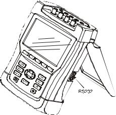
The Analyzer has a tilt stand that allows viewing the screen at an angle when placed on a flat surface. With the tilt stand folded out, the optical RS-232 port can be accessed at the right side of the Analyzer as shown in the figure.
Figure 4-1. Tilt stand and location of RS-232 interface
4-1
Fluke 434/435
Users Manual
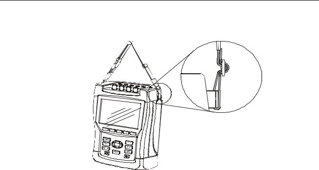
A hang strap is supplied with the Analyzer. The figure below shows how to attach the strap correctly to the Analyzer.
Figure 4-2. Fixing the hang strap
Powering the Analyzer
The Analyzer has a built-in rechargeable NiMH battery that can power it for more than 6 hours when fully charged. When powered by the battery, the battery condition symbol in the screen header indicates the charge condition. This symbol ranges from fully charged to empty:  .
.
When empty allow the batteries to fully charge with the Battery Charger/Power Adapter model BC430. A full charge takes at least 4 hours with the Analyzer turned off. When turned-on charging takes much longer.
No damage will occur if the charger is connected for long periods, e.g. over the weekend. The Analyzer automatically switches to trickle charging. At delivery the battery may be empty and it is recommended to charge it before use.
Concerning the use of the Battery Charger/Power Adapter bear the following in mind:
•Use only the supplied Battery Charger/Power Adapter model BC430.
•Before use check that the BC430 voltage and frequency match the local line power range.
If necessary set the slider switch of BC430 to the correct voltage.
•Connect the Battery Charger to the ac outlet.
•Connect the battery charger to the POWER ADAPTER input on the top side of the Analyzer.
•To avoid overheating of the battery during charging, do not exceed the allowable ambient temperature as given in the specifications.
4-2
Basic Operations and Menu Navigation |
4 |
Display Brightness |
Caution
To prevent decrease of battery capacity, charge it at least twice a year.
Power On/Off:
Press to power up or down with the last setup configuration. The welcome screen shows what Analyzer settings are currently in use. At power on a single beep can be heard.
To save battery power, the Analyzer display dims automatically when no keys are operated during a certain time. This time is adjustable.
When a key is operated, the display turns on again.
For the adjustment of Auto-off time see Chapter 20, USER PREFerences.
Attention: the Analyzer switches off automatically when powered by battery only if no further knobs are operated after power-on (i.e. when the welcome screen is displayed).
Display Brightness
Press repeatedly to dim/brighten the backlight.
Keep pressed for more than 5 seconds for extra brightness for better visibility in strong sunlight.
Low brightness saves battery power.
Locking the keyboard
The keyboard can be locked to prevent unwanted operation during unattended measurements:
ENTER |
Press for 5 seconds to lock or unlock the keyboard. |
Menu Navigation
Most of the Analyzer functions are menu operated. Arrow keys are used to navigate through menus. The Function keys F1 ... F5 and the ENTER key are used to make selections. Active Function key selections are highlighted with a black background.
How to use the menus is illustrated in the example below on how to adjust the Analyzer for use with a certain printer type.
SETUP
F4
The SETUP menu pops up.
Submenu SETUP USER PREF appears.
Highlight Printer:  .
.
ENTER
The PRINTER submenu appears. In this menu you can adjust printer type and baudrate.
4-3

Fluke 434/435
Users Manual
ENTER
F5
Highlight baudrate:  .
.
Adjust the required transmission speed.
Highlight the Printer type you want to use:  .
.
Press to confirm the selection.
Press to return to the next higher menu SETUP USER PREF. This menu is the starting point for many adjustments such as Display Contrast Adjustment and Reset to Factory Defaults.
Display Contrast
Use submenu SETUP USER PREF as a starting point. How to get there is explained above under Menu Navigation:
Adjust the Display Contrast to your personal taste.
Reset to Factory Defaults
Proceed as follows to reset the Analyzer to factory default settings. Bear in mind that recorded data and adjustments will be lost.
Use submenu SETUP USER PREF as a starting point. How to get there is explained above under Menu Navigation:
|
|
|
|
Press to start the reset to default settings. Because of the risk |
|
F1 |
|
||
|
|
|
|
of unwanted erasure of data, a confirm menu pops up. |
|
|
|
|
|
|
|
|
|
Press to confirm the reset. |
|
F5 |
|
||
|
|
|
|
|
Proceed as follows to reset the Analyzer to factory default settings without loss of data: turn power off, then press and hold SAVE SCREEN and turn on again. You should hear a double beep.
4-4
Chapter 5
Display Information
Introduction
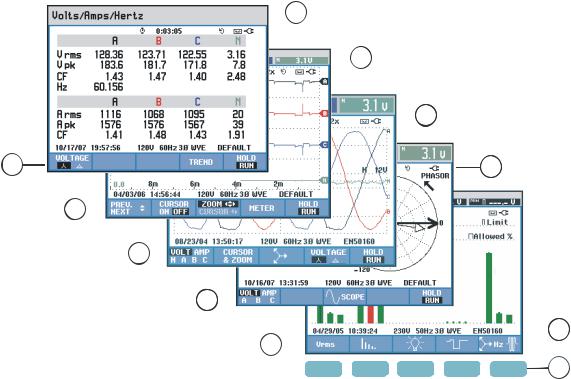
The Analyzer uses five different screen types to present measuring results in the most effective way. The features these screens have in common are explained in this chapter. Details that are specific for a certain measuring mode are presented in the chapter explaining that mode. The screen header is presented in the selected information language. The figure below gives an overview of the screen types 1 .. 5; common features are explained under A ... F.
 A
A
 B
B
 C
C
1 |
D |
2 
3 
4 
 E
E
5 
F1 |
|
F2 |
|
F3 |
|
F4 |
|
F5 |
F |
Figure 5-1. Survey of Display Types
5-1

Fluke 434/435
Users Manual
Phase Colors
Measuring results belonging to different phases are presented with individual colors. If - for a certain phase - voltage and current are displayed simultaneously, the voltage color has a dark tone and the current has a light tone. The set of phase colors can be chosen via the SETUP key and function key F4 – USER PREF. For detailed information see Chapter 20.
Screen Types
Below you will find a brief description of each screen type and its purpose. The measuring mode it is used for is given as well as the manual chapter with detailed information. Bear in mind that the amount of screen information depends on the number of phases and the wiring configuration. Refer to Figure 5-1, item 1 ... 5.
1Meter screen: gives an instantaneous overview of a big number of important numerical measuring values. Used for: Volts/Amps/Hertz (Chapter 8), Dips & Swells (Chapter 9), Harmonics (Chapter 10), Power & Energy (Chapter 11), Flicker (Chapter 12), Unbalance (Chapter 13), and Power Quality Monitoring (Chapter 18).
2Trend screen: this type of screen is related to a Meter screen. Trend shows the course over time of measuring values from the Meter screen. After selection of a measuring mode, the Analyzer starts recording all readings in the Meter screen. Used for: Volts/Amps/Hertz (Chapter 8), Dips & Swells (Chapter 9), Power & Energy (Chapter 11), Flicker (Chapter 12), and Inrush Currents (Chapter 15).
3
4
Waveform screen: shows voltage and current waveforms as displayed on an oscilloscope. Channel A (L1) is reference channel and 2 complete cycles starting at 0 volt are displayed. The nominal voltage and frequency determine the measuring grid size. Used for: Scope Waveform (Chapter 7) and Transients (Chapter 14).
Phasor screen: shows the phase relation between voltages and currents in a vector diagram. The vector of reference channel A (L1) points to the positive horizontal direction. The A (L1) amplitude is also reference for the measuring grid size. Used for: Scope Phasor (Chapter 7) and Unbalance (Chapter 13).
5Bar Graph screen: shows the density of each measuring parameter as a percentage by means of a Bar Graph. Used for: Harmonics (Chapter 10) and Power Quality Monitor (Chapter 18).
5-2

Display Information 5
Screen information common for all screen types
Screen information common for all screen types
Refer to Figure 5-1, item A ... F
A
B
Measuring mode: the active measuring mode is shown in the screen header.
Measuring values: main numerical measuring values. Background colors differ per phase and for voltage or current. If Cursor is on, the values at the Cursor are shown.
C
D
Status indicators. The following symbols may appear on the screen to show the state of Analyzer and measurements:
 : Indication that the 150/180 cycle (3 s) aggregation interval (50/60 Hz) is active. With no indication, the aggregation interval is 10/12 cycles (50/60 Hz).
 Time that a measurement has been going on. Format: hours, minutes, seconds. When waiting for a timed start, time counts down with prefix -.
 Horizontal ZOOM on.
 Measurement may be unstable. E.g. applicable for frequency readout during absence of voltage at reference phase A (L1).
 Indicates according to IEC61000-4-30 flagging convention that a dip, swell or interruption has occurred during the displayed aggregation interval. Indicates that an aggregated value may not be reliable.
 Recording of measurement data is on.

 Phasor rotation / Phase sequence indicator.

 Battery/Line power indication. During battery operation the battery charge condition is displayed.
 Keyboard locked. Press ENTER 5 seconds to unlock/unlock.
Main area with measuring data: features are explained under 1 ... 5.
5-3

Fluke 434/435
Users Manual
EStatus line: following information appears on the screen. How to adjust these items is explained in Chapter 20 – General Settings. Following information is given:
 Date of Analyzer’s real time clock. Date format may be month-day-year or day-month-year.
 Time of day or cursor time.
 Nominal line voltage and frequency: are a reference for the measurements.


 GPS signal strength indicator.
 Number of phases and wiring configuration for the measurement.
 Name of the limits used for the power quality MONITOR, dips, swells, interruptions, rapid voltage changes.
FSoftkey text area: softkey functions that can be selected with F1 ... F5 are indicated in white. Functions currently not available are indicated in gray. Active Function key selections are highlighted with a black background.
5-4
Chapter 6
Input Connections
Introduction
This chapter explains how to make connection to the power distribution system under test and how to adjust the Analyzer settings.
Check that the Analyzer setup meets the characteristics of the system under test and the accessories that are used. This concerns:
•wiring configuration
•nominal frequency
•nominal voltage
•properties of voltage leads and current clamps
The actual setup is shown in the welcome screen that appears after power up. To change the setup, refer to Chapter 20.
Input Connections
The Analyzer has 4 BNC-inputs for current clamps and 5 banana-inputs for voltages.
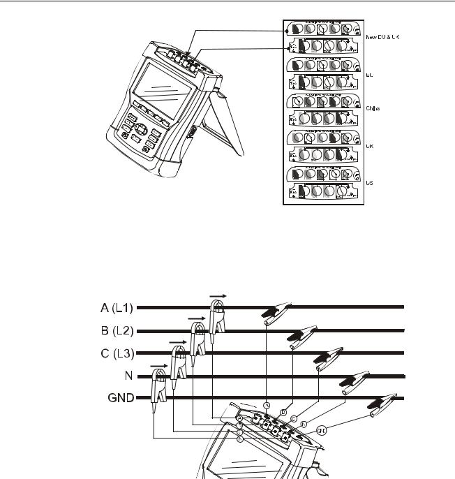
Self-adhesive decals are supplied corresponding to wiring color codes used in the USA, Canada, Continental Europe, the UK, and China. Stick the decals that fit to your local wiring codes around the current and voltage inputs as shown in Figure 6-1.
6-1
Fluke 434/435
Users Manual
Figure 6-1. Mounting the decals for voltage and current inputs
De-energize power systems before making connections whenever possible. Always use appropriate equipment for personal protection. Avoid working alone and work according to the warnings listed in Chapter 1, Safety Information.
For a 3-phase system make the connections as shown in Figure 6-2.
Figure 6-2. Connection of Analyzer to 3-phase distribution system
First put the current clamps around the conductors of phase A (L1), B (L2), C (L3), and N(eutral). The clamps are marked with an arrow indicating the correct signal polarity.
Next make the voltage connections: start with Ground and then in succession N, A (L1), B (L2), and C (L3). For correct measuring results, always connect the Ground input. Always double-check the connections. Make sure that current clamps are secured and completely closed around the conductors.
For single phase measurements, use current input A (L1) and the voltage inputs Ground, N(eutral), and phase A (L1).
A (L1) is the reference phase for all measurements.
6-2
Input Connections 6
Input Connections
Before making any measurements, set the Analyzer up for the line voltage, frequency, and wiring configuration of the power system you want to measure. This is explained in Chapter 20, General Settings.
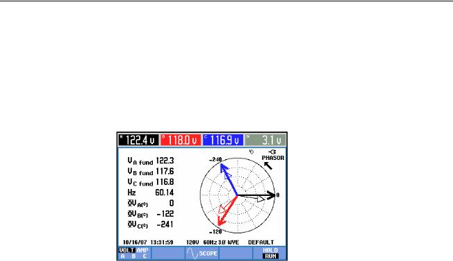
Scope Waveform and Phasor display are useful to check if voltage leads and current clamps are connected correctly. In the vector diagram the phase voltages and currents A (L1), B (L2), and C (L3) should appear in sequence when observing them in clockwise direction as shown in the example in Figure 6-3 (This type of vector diagram is displayed after reset of the Analyzer to factory defaults as explained on page 4-4).
Figure 6-3. Vector diagram for correctly connected Analyzer
6-3

Fluke 434/435
Users Manual
6-4
 Loading...