

Page 1

®
Fluke 39/41B
Power Harmonics Tester
4822 872 00916
July 1995 Rev. 3, 11/00
© 1995 Fluke Corporation. All rights reserved. Printed in the Netherlands.
All product names are trademarks of their respective companies.
Users Manual
Page 2

LIMIT E D WARRANTY & LIM ITATIO N OF LIABILITY
Each Fluk e produc t is warranted t o be f ree from defects in material and workmanship under
normal use and serv i ce. The warranty peri od i s one year and begins on t he dat e of shipment.
Parts, product repairs and s ervices are warrant ed for 90 days. Thi s warranty extends only t o the
original buyer or end-user customer of a Fl uke authorized res el l er, and does not apply to fuses,
disposable bat t eri es or to any product which, in Fl uke’s opinion, has been mi sused, altered,
neglected or damaged by accident or abnormal conditions of operation or handling. Fluke warrants that software will operate substantially i n accordance wit h i t s functi onal s pecifications for
90 days and that i t has been properly rec orded on non-defective m edi a. Fluke does not warrant
that software will be error free or operate without i nt erruption.
Fluke authorized resellers shall extend t hi s warranty on new and unused products to end-us er
customers only but hav e no aut hori ty to ext end a greater or different warranty on behalf of
Fluke. Warranty support is available if produc t is purchas ed through a Fluke authorized sales
outlet or Buy er has paid the applic abl e i nt ernational price. Fl uke reserves the right to invoice
Buyer for im port ation cost s of repair/replac em ent parts when product purchased in one c ount ry
is submitted for repair in anot her country.
Fluke’s warranty obligation i s limited, at Fluke’s opti on, to refund of t he purchase price, free of
charge repair, or replac em ent of a defecti v e produc t which is returned to a Fluke aut hori zed
service center within the warranty period.
To obtain warranty service, contact your nearest Fluk e authorized serv i ce center or send t he
product, wit h a description of the diffic ul ty, post age and i nsurance prepaid (FOB Des tination), t o
the nearest Fluke authorized s ervice cent er. F l uke assumes no ri sk for damage in transit.
Following warranty repai r, the product will be returned to Buyer, t ransportation prepaid (FOB
Destination). If Fluk e determines that the failure was caused by misuse, alteration, acc ident or
abnormal conditi on of operation or handling, Fl uk e will provide an estimate of repair costs and
obtain authorization before comm encing the work. F ol l owi ng repai r, the product will be returned
to the Buyer transportation prepai d and the Buyer will be billed for the repair and return transportation charges (F OB Shipping Point ).
THIS WARRANTY IS BUYER’S SOLE AND EXCLUSIVE REMEDY AND IS IN LIEU OF ALL
OTHER WARRANTIES, EXPRESS OR IMPLIED, INCLUDING BUT NOT LIMITED TO ANY
IMPLIED WARRANTY OF MERCHANTABILITY O R F I T NESS FOR A PARTICULAR PURPOSE. FLUKE SHALL NOT BE LIABLE FOR ANY SPECIAL, INDIRECT, INCIDENTAL OR
CONSEQUENTIAL DAMAGES OR LOSSES, INCLUDING LOSS OF DATA, WHETHER
ARISING FROM BREACH OF WARRANTY OR BASED ON CONTRACT, TORT, RELIANCE
OR ANY OTHER THEORY.
Since som e countries or s t ates do not allow l i m i t ation of the term of an implied warranty, or
exclusi on or l i m i t ation of incidental or consequent i al damages, the li m i t ations and exc l usions of
this warranty may not apply to every buyer. If any prov i sion of this Warranty is held i nvalid or
unenforceable by a court of competent jurisdi ction, such holding will not affect the validity or
enforceability of any other provision.
Fluke Corporation Fluke Europe B.V.
P.O. Box 9090 P.O. Box 1186
Everett WA 5602 B.D. Ei ndhoven
98206-9090 The Netherlands
Page 3

SERVICE CENTERS
To locat e an authori zed ser vi ce center, vis it us on the World Wide Web:
http://www.fluke.com
or call Fluke using any of the phone numbers listed below:
+1-888-993-5853 in U.S.A. and Ca nada
+31-402-678-200 in Eur ope
+1-425-356-5500 from other countries
Page 4

Page 5

Table of Contents
Title Page
Safety ................................................................................................ v
About This Manual............................................................................. 1
Uses for the Tester ............................................................................. 1
Unpacking.......................................................................................... 2
Terminology Used in This Manual...................................................... 5
Battery Considerations ....................................................................... 6
Memory Retention.............................................................................. 6
Automatic Power Down...................................................................... 6
Getting Acquainted with Your Tester................................................. 7
Input Connections............................................................................... 9
Using the Voltage Test Leads........................................................ 9
Using the Current Probe................................................................ 10
Three-Phase Power Measurements..................................................... 11
Keypad............................................................................................... 14
Display Screen................................................................................... 19
Functions and Screen Modes.............................................................. 25
Waveform Screen Mode................................................................ 25
Harmonics Screen Mode................................................................ 27
Harmonics Zoom Mode ................................................................. 30
Text Screen Mode......................................................................... 31
VA Check Screen ............................................................................... 33
Recording Measurements ................................................................... 35
Power-Up Configuration..................................................................... 37
Storing & Recalling Measurements (Model 41B)................................ 39
Using the Serial Cable (Model 41B)................................................... 41
Printing (Model 41B)......................................................................... 43
Sending to a Printer or PC (Model 41B)............................................. 43
Using PC Software With the Tester (Model 41B) ............................... 43
Applications....................................................................................... 44
Plant Switch Gear (Service Entrance)............................................ 46
Distribution Transformer............................................................... 47
Electronic Equipment Load Center ................................................ 48
Generator Set................................................................................ 50
i
Page 6

Fluke 39/41B
Users Manual
Adjustable Frequency (Speed) Motor Drive................................... 51
User Maintenance.............................................................................. 52
Cleaning........................................................................................ 52
Fuse Replacement......................................................................... 52
Battery Replacement ..................................................................... 52
Operational Test............................................................................ 54
If the Screen Flashes or is Blank at Power-Up ............................... 54
If Your Tester Does Not Work....................................................... 54
Accessories and Replacement Parts.................................................... 55
Specifications..................................................................................... 57
ii
Page 7

List of Tables
Table Title Page
1. Key Descriptions...................................................................... 15
2. Status Line............................................................................... 20
3. Screen Abbreviations................................................................ 21
4. Special Messages ..................................................................... 24
5. Replacement Parts.................................................................... 56
iii
Page 8

List of Figures
Figure Title Page
1. Tester and Accessories............................................................. 3
2. Additional Items (Model 41B).................................................. 4
3. Getting Acquainted.................................................................. 8
4. Measurement Connections (1
5. Three-Phase Measurement Connections
(For Balanced Circuits, 3
6. Three-Phase Measurement, Balanced or Unbalanced Connections
P
, 3-Conductor, D or Y)................................................... 12
(3
7. Three-Phase Measurement, Balanced or Unbalanced Connections
P
, 4-Conductor) ................................................................... 13
(3
8. Keypad..................................................................................... 14
9. Display Screen......................................................................... 19
10. Waveform Screens.................................................................... 26
11. Harmonics Screens................................................................... 28
12. Harmonics Overload Screen ..................................................... 29
13. Harmonics Zoom Screen........................................................... 30
14. Text Screens ............................................................................ 32
15. Typical VA Check Signatures................................................... 34
16. Record Screens......................................................................... 36
17. Configuration Screens.............................................................. 38
18. Memory Screen........................................................................ 39
19. Serial Communications (Model 41B)........................................ 42
20. Typical Applications................................................................. 45
21. Plant Switch Gear .................................................................... 46
22. Distri buti on Transformer (1
23. Distri buti on Transformer (3
24. Receptacle Load Center (Neutral Current Measurement).......... 49
25. Generator Set........................................................................... 50
26. Adjustable Frequency Motor Drive........................................... 51
27. Battery Replacement ................................................................ 53
P
) .............................................. 10
P
, 3-Conductor, D).......................... 11
P
Watts Text Screen) ................... 47
P
, 3C Watts Text Screen)............. 48
iv
Page 9

Using Your Tester Safely
!
Warning
To avoid electric sh ock, use on ly the test leads supplied
with the Tester. Use 600V rat ed probe tip adapters.
(“600V” is printed o n the equipment.) Remove all test
leads that are not in use.
Use only the 80i-500s ac current probe or a safet ydesigned equivalent (such as t he Fluke M odel 80i-1000s)
that is rated for 600V on both th e jaws and the measuring
secondary. Remove any current probe that is not in use.
In this manual, a WARNING identifies conditions and actions that pose hazard(s) to the user. A Caution identifies conditions and actions that may damage the tester or the current probe. See below for explanations of international
electrical symbols.
Read the following safety information carefully before attempting to operate
or ser vice th e Tester or the current probe.
!
DANGEROUS VOLTAGE
AC-ALTERNATING CURRENT
DC-DIRECT CURRENT
Either DC or AC
EARTH
CAUTION see explanation in
manual
Equipment protected throughout
by DOUBLE INSULATION or
REINFORCED INSULATION
RECYCLING
HIGH BNC INPUT
International Safety Symbols
Safety Guidelines for Tester and Voltage Probe
To ensure that you use your Tester safely, follow these guidelines:
• Avoid working al one.
• Inspect the test leads for damaged insulation or exposed metal. Check test
lead continuity with a multimeter. Replace damaged leads.
• Do not use the Tester if it looks damaged.
v
Page 10

• When using the voltage test leads, keep your fingers away from the probe
conta cts. Keep your fingers beh ind the fi nger guards on the probes.
• Use cauti on wh e n m easu ring above 60V-d c or 30V-ac r ms. S uch voltages
pose a shock hazard.
AC Current Probe Safety Guidelines
Follow these safety guidelines when using the AC Current Probe:
•
!
Never use the 80i-500s current probe on circuits rated higher t han
600V. Use extreme caution when clampin g t he current probe around uninsulated conductors or bus bars.
• Keep your fingers behind the finger guard on the 80i-500s.
• Check the magnetic mating surfaces of the probe jaws; these should be
free of dirt, dust, rust, or other foreign matter.
• Do not use a current probe that has been cracked or damaged or has de-
fective leads. If there is any such sign of impaired operation, tape the
probe shut to prevent operation.
• The 80i-500s has been designed and tested according to IEC 1010-1:1992
and other safety standards. Follow all warnings to ensure safe operation.
vi
Page 11

About This Manual
This manual contains instructions for the 39 and 41B Power Harmonics
Testers (hereafter referred to as the Tester). All information applies to both
models unless otherwise indicated.
Uses for the Tester
You can use the Tester to measure voltage and curr ent i nputs at power line
and harmonic frequencies. Using these inputs, the Tester automatically
calculates power and a wide ran ge of other measurements useful in
determining harmonic distortion levels and sources. The Tester can display
power calculations in either a single-phase or a 3-phase readout.
These capabilities allow you to monitor power quality before and after an
installation, troubleshoot a power distribution system, and (with Model 41B)
print out or download data for additional analysis.
The Tester is both a harmonics measurement tool and a power meter or
digital multimeter. You can use the Tester to measure voltage events
(undervoltage, overvoltage, line outages, and neutral to ground levels),
current levels, or to measure power levels. Fundamental frequency
measurements (to 100 Hz) and harm oni c frequency measurements (to about 2
kHz) are also possible.
The Tes ter c an not measure fr equencie s above about 2 kHz. (Use the
ScopeMeter test tool to measure fast power transients.)
1
Page 12

39/41B
Users Manual
Unpacking
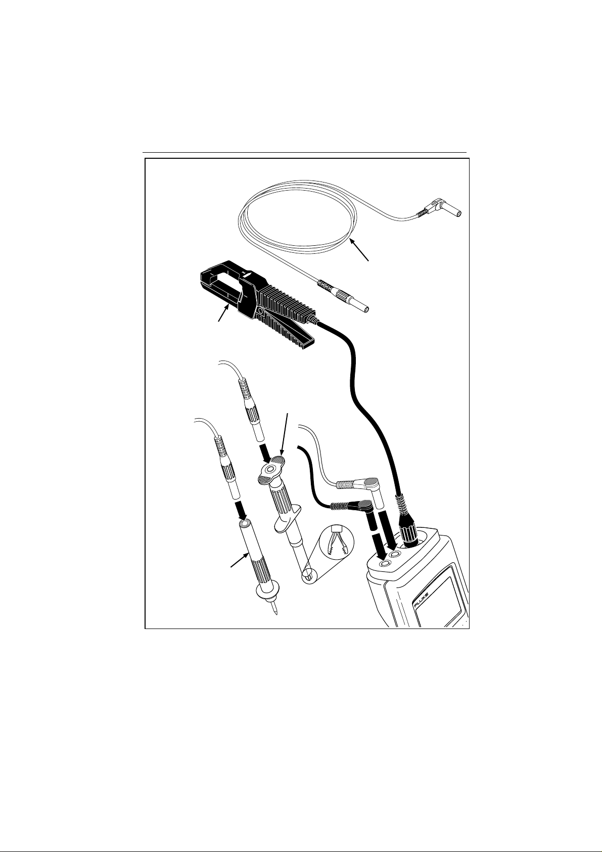
The following items are included in your tester kit (see Figure 1):
• Model 39 Power Meter or Model 41B Power Harmonics Analyzer
• 80i-500s AC Current Pr obe
• TL-24 Test Leads
• TP-20 Test Probes
• AC-20 Test Clips
Your kit also includes the following printed materials:
• Users Manual ( th is book)
• Quick Reference Guide
• Warranty Registration Card
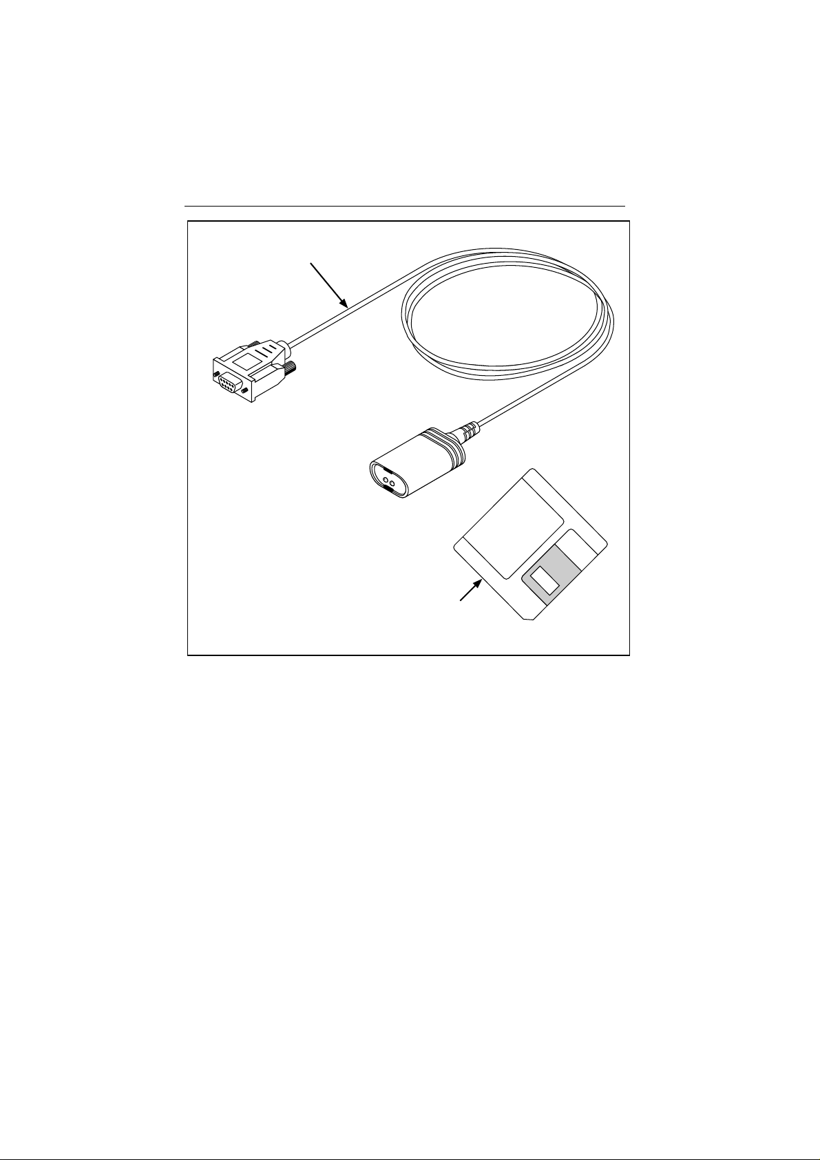
For Model 41B only, the following additional items are included. Refer to
Figure 2.
• RS-232 Serial Cable
• FlukeView 41 Win dows Software Disk
Check the contents of the box for completeness, noting any damage. If
something in the kit has been damaged or is missing, contact the supplier
immediately.
2
Page 13
80i-500s
AC Current
Probe
AC-20
Test Clip
Unpacking
TL-24
Test Leads
(Set of two. Red and Black)
TP-20
Test Probe
Figure 1. Tester and Accessori es
41
®
POWER HARMONICS
ANALYZER
a2f.eps
3
Page 14
39/41B
Users Manual
RS-232 Cable
Companion Software
3.5-Inch Floppy Disks (FlukeView 41)
a3f.eps
Figure 2. Additi onal Items (M odel 41B)
4
Page 15

Terminology Used in This Manual
Terminology Used in This Manual
This manual uses the following standard terminology:
• “Mains” is line voltage or frequency.
• “φ1”, “φ2”, and “φ3” refer to the three current supply phases.
• “Delta”
• “Wye”
• “N” is Neutral.
•
e
• “AC Current Probe” or “Probe” refers to the 80i-500s, which can al so be
call ed a “cur rent clamp”.
D
.
Y
.
is Earth ground.
5
Page 16

39/41B
Users Manual
Battery Considerations
New alkaline C cells typically provide more than 48 hours of continuous
operation. You can also use NiCad batteries. However, depending on batter y
condition, fully charged NiCad batteries provide 16 hours or less of
continuous operation.
b
Plan to replace the batteries as soon as possible after the
Refer to User Maintenance later in this manual for battery changing
instructions.
Note
After the Tester is dropped, it may not turn on. Check the batteries
to see if they are misaligne d or damaged. R e seat t he batt e rie s if t hey
are misaligned; replace the batt e ries if t hey are damaged.
symbol comes on.
Memory Retention
Whenever you rem ove power from the Tester ( p ressi ng O off, letting the
batteries run down, removing the batteries, or experiencing an automatic
power down), the Tester retains all essential operating information in
nonvolatile memory. Specifically, the Tester retains calibration accuracy,
power-up configuration information, and a ny stored waveforms (Model 41B).
However, if you remove power when Record is active, the Tester loses all
recor d ed values.
Automatic Power Down
If you do not press any keys for approximately 15 minutes, the Tester
normally powers down automatically. If Record is active, the Tester continues
to operate unattended as long as the battery condition allows.
The Tester returns to its power-up configuration whenever you turn it on.
If the Tester encounters a memory error at power-up, it automatically turns
itself off. Check the batteries and try turning the Tester on again. If this
problem per sists, contact a F luke Service Center .
6
Page 17
Getting Acquainted with Your Tester
Getting Acquainted with Your Tester
While referring to Figure 3, perform the following key presses to familiarize
yourself with basic tester operations.
o
to turn the Tester on.
1.
2.
c
(brief press) and
C
(hold 1 second) to turn the backlight on or off.
3.
F
to select a measurement function (Volts, Amps, Watts).
M
4.
5.
<
F
R
6.
to select a screen mode (Waveform, Harmonics, Text ).
R
to start recording measurements
or
>
to select NOW, MAX, AVG, MIN recording.
to select a different measurement function while recording.
to exit recording.
o
to turn the Tester off.
<
or
>
to cha nge screen contrast .
7
Page 18

39/41B
Users Manual
®
41
POWER HARMONICS
16
ANALYZER
3
5
2
4
a4f.eps
Figure 3. Get t i ng Acquai nted
8
Page 19

Input Connections
Input Connections
Refer to Figure 4 for a view of the two-input measurement scheme. To
measure voltage, insert the red test lead in “V” and the black test lead in
“COM.” Curren t measu rement us es a BNC connector attach ed to “CURRENT
PROBE.” Connect “V” and “COM” to measure only voltage; connect
“CURRENT PROBE” to measure only current. Make all three connections for
power measurements.
Observe the following connection guidelines:
• Current
Clamp the Current Probe around the desired phase or neutral conductor.
Make sure the arrow on the probe points toward the load (phase) or the
source (neutral). The Tester is set up for use with an 80i-500s Curr ent
Probe. If you use another pr obe, you must make a selection change in t he
Configuration Screen.
• Voltage: 3-phase, 4-Wire
Connect the red test lead to the desired phase voltage; connect the black
test lead to neutral.
• Voltage: 3-phase, 3-Wire, example
Connect the r ed test lead to t he phase con d uctor u s ed by the Current
Probe; connect the black test lead to another phase.
D
Using the Voltage Test Leads
The TL-24 Test Lead and AC-20 Test Clip combination (Figure 1), which
all ows for hands-free volta ge measu rements, is preferred when you ar e also
using the Current Probe.
Note
Figure 4 shows suggested test lead and current probe usage.
9
Page 20
39/41B
Users Manual
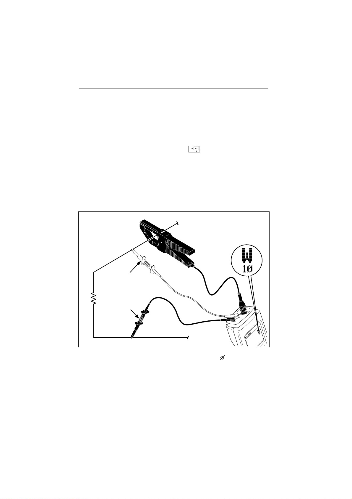
Using the Current Probe
The accuracy of current an d power readin gs depends on properly using the
80i-500s Current Probe. The accuracy specifications in this manual a ssume
that the Current Probe is used correctly.
• Always clamp the 80i-500s Curr en t Probe with the arrow pointing toward
the load (away from the source) for a phase measurement or toward the
G
source for a neu tra l meas u rement. Press
orientation. If the resulting VA Check Screen generally extends from the
lower left to the upper right of the screen, the Current Pr obe is connected
properly.
• Always clamp the Current Probe around a single conductor or parallel
conductors t hat are carrying current for the sam e pha se.
• Always center the conductor in the Current Probe alignment marks.
Line
to verify the Current Probe
10
Load
Red
Black
N
Figure 4. Measurem ent Connect i ons ( 1P)
POWER HARMONICS
ANALYZER
41
®
a5f.eps
Page 21

Three-Phase Power M eas ur em ents
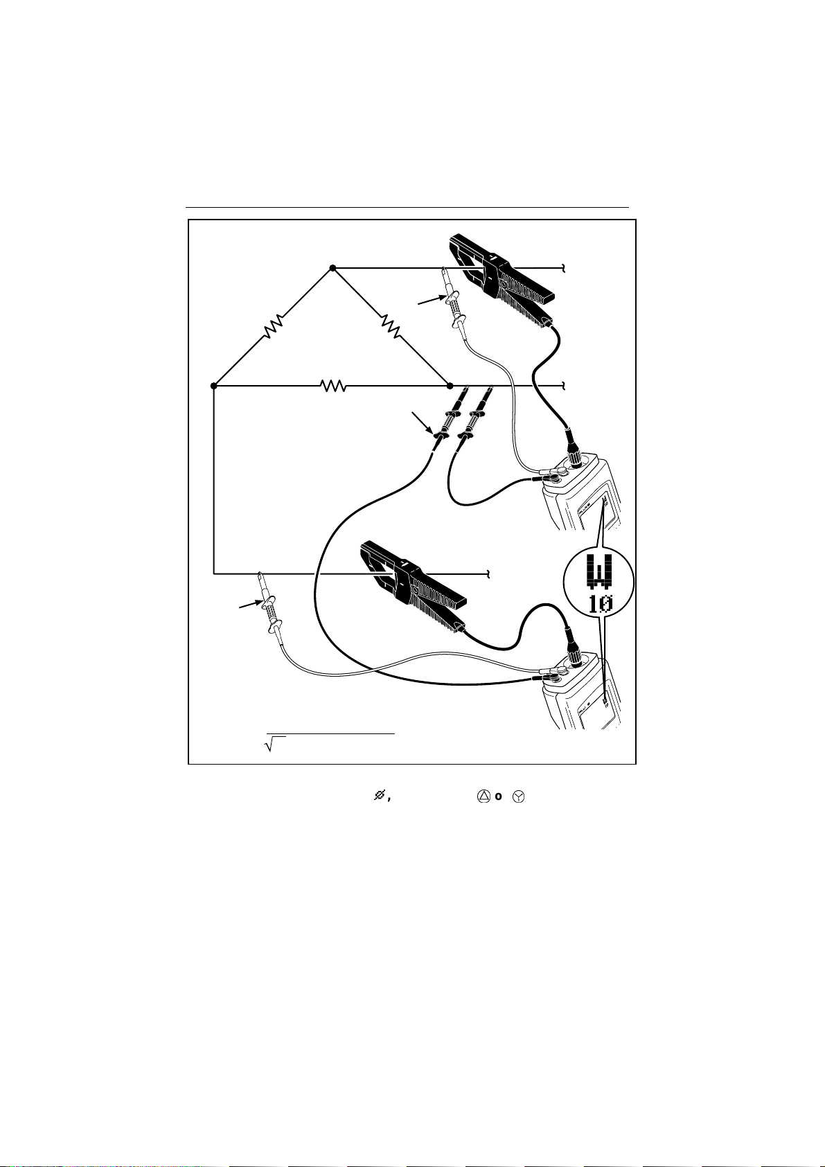
Three-Phase Power Measurements
Refer to Figures 5, 6, and 7 for various ways to measure total power in a
W 3
P
three-phase s ystem . The
calculation for the connection shown in Figure 5. All other screens and
functions show only single-phase data.
3C display screen shows the three-phase
Load
Red
Black
W
φ
1
φ
2
POWER HARMONICS
ANALYZER
41
®
1
φ
3
a74f.eps
Figure 5. Three-Phase M easur em ent Connect i ons (For Balanced Circuit s,
P
, 3-Conductor, D)
3
11
Page 22
39/41B
Users Manual
Red
Load
Red
Black
φ
1
φ
2
POWER HARMONICS
ANALYZER
41
®
W
1
φ
3
W
PF =
= W1 + W
total
W1 + W
3
(VA
2
2
+ VA2)
1
/2
Figure 6. Three-Phase M easure ment, Balanced or Unbalanced
P
Connections (3
, 3-Conductor, D or Y)
12
W
POWER HARMONICS
ANALYZER
41
®
2
a6f.eps
Page 23
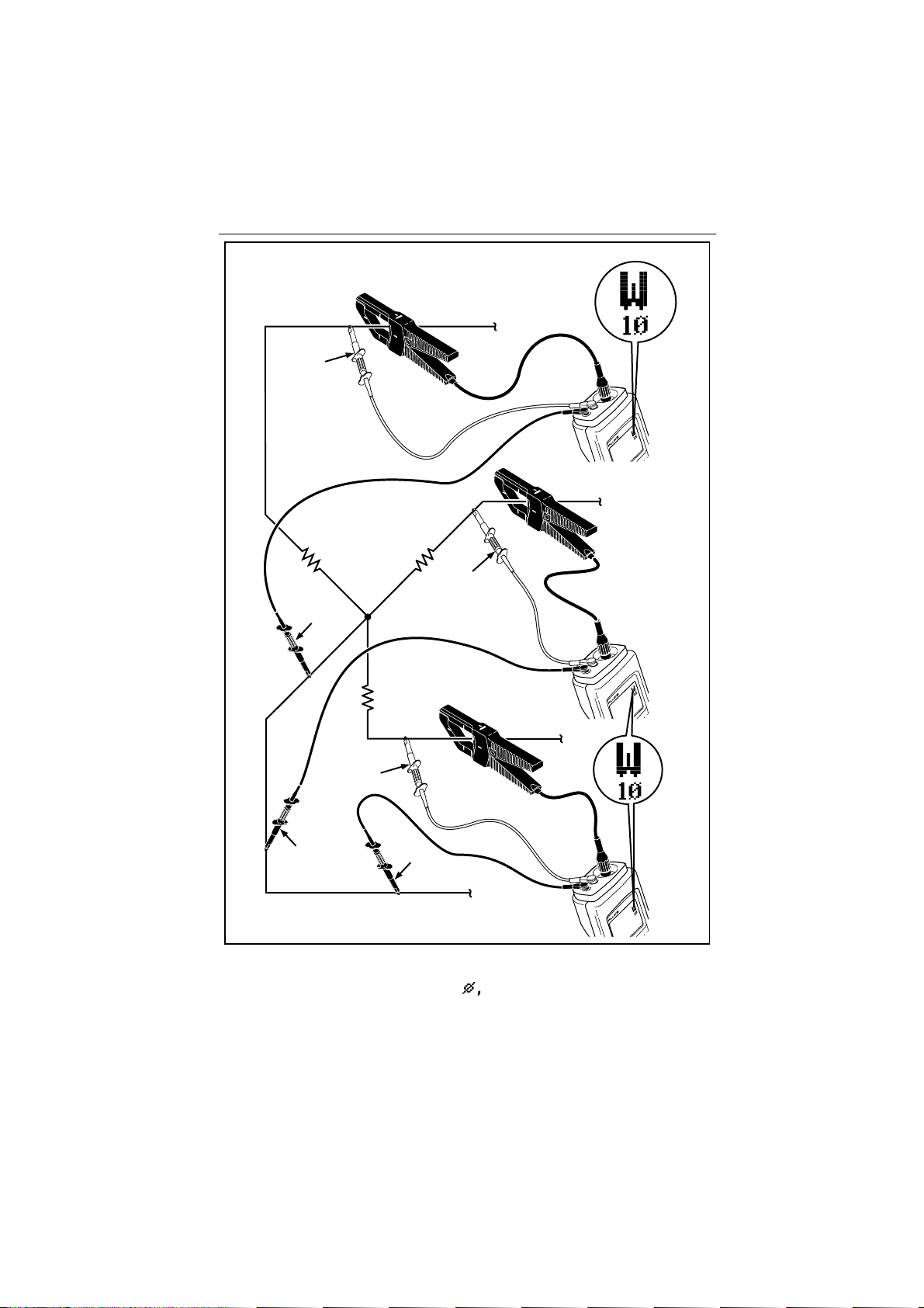
Red
Three-Phase Power M eas ur em ents
φ1
POWER HARMONICS
ANALYZER
41B
®
W
1
φ2
Load
Red
Black
POWER HARMONICS
ANALYZER
41B
®
W
2
φ3
Red
Black
Black
W
= W1 + W2 + W
total
N
3
W
3
POWER HARMONICS
ANALYZER
41B
®
Figure 7. Three-Phase M easure ment, Balanced or Unbalanced
P
Connections (3
, 4-Conductor)
a7f.eps
13
Page 24

39/41B
Users Manual
Keypad
Refer to Figure 8 and Table 1 for keypad operation.
14
13
12
11
1
10
2
9 89 8
Figure 8. Keypad
3
4
5
6
7
a8f.eps
14
Page 25

Table 1. Key Descriptions
Number Symbol Name & Description
Keypad
1
2
O
<
>
3
4
c
M
Power
Press once to turn the Tester on; a test pattern is
displayed briefly. (Test pattern rem ains displayed
while key is held pressed.) Press again to turn
the Tester off. The Tester sets up to the powerup configuration each time you turn it on.
Arrow Keys
These keys have multiple uses. Refer to other
areas for specific
Contrast/Backlight
Tap briefly to adjust contrast ( with
tap again to store sett ing and ret ur n t o nor m al
operation. Press and hold
to turn the backlight on or of f .
Screen Mode
Press to cycle the Tester th rough Waveform,
Harmonics, and Text Screen Modes. You select
the Measurement Function (Volts, Amps, or
Watts) independently of the Screen Mode.
<
and
>
descriptions.
< >
C
for about 1 second
);
15
Page 26

39/41B
Users Manual
Table 1. Key Descriptions ( cont)
Number Symbol Name & Description
5
6
r
G
Range (Waveform and Text)
Press
r
momentarily to star t m anual r anging
(MAN) for all Measurement Funct ions ( V, A, W).
Continue momentary presses to cycle thr ough
the ranges for the selected M easur em ent
Function only. (Ranges do not change for the
other two Measurement Funct ions. ) Press and
hold about 1 second to return t o aut or anging
(AUTO) for all Measurement Funct ions ( V, A, W).
The Tester always begins autoranging at powerup.
Range (Harmonics)
Press
r
momentarily to cycle from 100% t o
10%, 20%, 50%, and back t o 100% . Other
harmonics screen ranges and voltage or curr ent
measurement ranges do not change while in
harmonics display.
VA Check
Press at any time for a check of t he volts ver s us
amps signature at the test point . Press
second time to return t o nor m al oper at ion. See
also “VA Check” section.
G
a
16
7
m
Memory (Model 41B)
Press to access the Waveform St or age Screen.
Press
m
a second time to return t o nor m al
operation. Also, you can clear all stored
waveforms by holding
press
o
on. See also “Storing and Recalling
Measurements.”
m
pressed as you
Page 27

Table 1. Key Descriptions ( cont)
Number Symbol Name & Description
Keypad
10
8
9
f
s
S
Phase Reference
Press to select volts or amps as the display
phase reference. Voltage ref er ence is the
standard configuration. For cur r ent only
measurements, press
change the power-up phase reference, see
“Power-Up Configuration” later in this manual.
Send (Model 41B)
Press to print a test repor t of calculated
measurements to a pr inter or PC. ( The Test er
displays SEND.) Do not press
FlukeView 41 application software is in use. See
“Sending to a PC”.
Smooth
Smooth allows you to average waveforms,
resulting in a more stable screen and increased
accuracy of computations. ( See “Specifications.”)
Press
S
four times to step t hr ough t he
Smooth selections (
~
20s in the top status line). Pressing
fifth time ret ur ns t he Test er to normal operation.
f
to set AP. To
s
~
2s, ~5s, ~10s,
when
S
a
17
Page 28

39/41B
Users Manual
Table 1. Key Descriptions ( cont)
Number Symbol Name & Description
11
12
13
14
p
R
E
F
Print (Model 41B)
Press to print a screen dump to a pr int er . ( The
Tester displays
key. Do not press
application software is in use. See “Sending to a
PC”.
Record
Press to start Record. Press
to resume normal operat ion. You can also retur n
the Tester to its standar d ( factory-program m ed)
configuration by holding
Hold
Press
E
the top line.) You can now observe all screens for
a single measurement. Press
resume normal operation.
E
serves as the “ENTER” key when used with
some other screens. Also, you can access the
Power-Up Configuration Screen by pressing
as you press o on.
Measurement Function
Press to cycle the Tester through Volts, Amps,
and Watts Measurement Functions. You select the
Screen Mode (Waveform , Harm onic, or Text )
independently of the Measurement Function.
p
.) To stop printing, press any
p
when FlukeView 41
R
R
as you press on
to freeze the screen. (
E
a second time
o
H
appears in
again to
E
.
18
Page 29

Display Screen
Display Screen
The s creen consists of th e following three areas (see F igure 9):
• Status Line: identifies Tester operating conditions. See Table 2.
• Measurement Area: shows information as waveform, harmonics bar
chart, or set of text computations. Refer to Table 3 for abbreviations used
in all Measurement Functions and Screen Modes.
• Specia l Messag es . See Table 4.
Status Line (see Table 2)
Cursor Data
>30V rms Input or in Hold ( )
Low Battery Condition
Figure 9. Display Screen
Measurement Area
(see Table 3)
Special Screen Messages
(see Table 4)
a9c.eps
19
Page 30

39/41B
Users Manual
Table 2. Status Li ne
H
VP
AP
~
2s
~
5s
~
10s
~
20s
OL-V Volts Overload Condition for the selected range ( over 600V
OL-A Amps Overload Condition for the selected range ( exceeds
OL-VA Both volts and amps maximum inputs have been exceeded.
Hold active (screen frozen). L appears in lower left screen
to indicate possible high voltage input that is not sensed
during Hold.
Phase Reference Selection. The volts input or the current
input is the reference for det er m ining phase shift. Select
AP
when measuring current only with voltage test leads not
connected.
Smooth Selection. Smooth is active with averaging times of
2, 5, 10, or 20 seconds. A higher num ber signifies a mor e
stable measurement reading.
if in AUTO).
2V peak if in AUTO). Since the input from t he Curr ent Probe
is 1 mV/A, maximum current input is 2000A pk.
Note
When an overload occurs, all measurement and computation data
must be presumed invalid.
AUTO The Tester switches range automat ically to deal with
changing volts, amps, or watts r eadings.
MAN Test er does not switch r anges aut om at ically.
MEMX Memory location (X) last accessed. ( X = 1 to 8)
SEND Send is active (prints test report s , M odel 41B.)
PRNT Print is active (prints screen dumps, M odel 41B.)
20
Page 31

Display Screen
Table 3. Screen Abbreviations
Screen Usage Name and Description
°
d
Phase Angle degrees. (± 180°)
Measures time from t he positive zer o cr ossing of t he
fundamental of the selected volts or am p
represents one cycle at the fundam ent al or selected
harmonic frequency. A positive sign indicates that the
positive zero crossing of the measured cycle comes
earlier than (leads) that of t he r eference.
P
REF. 360°
Note
h
For the Watts
relation of Amps to the Volts
screen, the phase angle always shows the
P
REF at the same frequency. Cos
calculations are based on this defi ni ti on.
A RMS Amps RMS (includes dc component if using dc capable
current probe).
A PK Peak Amps (1/2 peak-to-peak value).
A DC Amps DC.
φ
A HM For a current waveform , A HM identif ies the t otal
harmonic current present .
A LEAD Amps Lead Volts
Evidence of capacitive reactance in the system; t he
current waveform pr ecedes t he voltage wavef or m .
A LAG Amps Lag Volts
Evidence of inductive reactance in the system; t he
current waveform occur s af t er t he volt age wavefor m .
CF Crest Factor
Ratio of a waveform’s peak value to its rms value.
21
Page 32

39/41B
Users Manual
Table 3. Screen Abbreviat i ons ( cont)
Screen Usage Name and Description
DPF Displacement Power Factor cosφ fundamental
The ratio of the active power (W ) t o t he apparent power
(VA rms) at the f undam ent al f r equency. Equivalent to
cos
φ at that frequency. Traditional power factor for linear
loads.
HZ Waveform Scr eens: Fundam ent al f r equency in hert z
Harmonics Screens: Frequency of selected harm onic in
hertz
KF K-Factor
A load current waveform rat ing calculation that r at es t he
waveform’s capability to produce harmonic-related heat
loss in transformers and other m agnet ic com ponent s.
Used to select transform er K-r at ings t hat m at ch load
current K-factor m easur em ent s.
PF Power Factor
Ratio of active power to apparent power ( including all
harmonics).True power factor for all loads, linear and
non-linear.
% THD-F Total Harmonic Distortion (as % of Fundamental)
Defines amount of harmonic distort ion as a per cent age
of the waveform at the fundamental frequency.
% THD - F = rms of harmonics (less f undam ent al)
rms of fundament al
% THD-R Total Harmonic Distortion (as % of rms t ot al)
Defines amount of harmonic distort ion as a per cent age
of the rms value of waveform s at all frequencies
(fundamental and harmonics).
% THD - R = rms of harmonics (less fundam ent al)
total rms
22
Page 33

Table 3. Screen Abbreviat i ons ( cont)
Screen Usage Nam e and Descri pt ion
V RMS Volts rms (includes dc component).
COS
P}
V PK Peak Volts (1/2 peak-to- peak value).
V DC Volts DC.
V HM Harm on ic Volts RMS
VA, KVA (Kilo) Volt Am p s
VAR, KVAR (Kilo) Volt Amps Reactive
Cosine of the angle between the voltage and the current
at any single frequency.
For a voltage waveform, V HM identifies t he t ot al
harmonic voltage present.
Apparent power: a value that the Tester calculates by
multiplying the rms value for current by t he r m s value f or
voltage.
The reactive power component of t he f undam ental
frequency.
Display Screen
W, KW Active Po we r
The average power dissipated (also called real power).
23
Page 34

39/41B
Users Manual
Table 4. Special Messages
<CONTRAST>
<
or
>
Press
store current set t ing.
The Tester has detected a calibration err or at power - up. Since err oneous
readings result, the Tester displays this message until calibration is verified.
Return the Tester t o a Service Center for repair or calibration. See “User
Maintenance” later in this manual.
to adjust contrast. Press C to exit contrast contr ol and
* CALIBRATION ERROR *
CONTACT FLUKE SERVICE
STOP AVG AT 48 HOURS
In Record, averaging stops aft er 48 hour s. Note t he aver age value shown;
then, press
recording with new values.
R
once to return to nor m al oper at ion or t wice t o begin
* PRINTING *
PRESS ANY KEY TO STOP
On Model 41B, this message appears when you press
any key to resume normal operat ion.
24
p
or
s
. Press
Page 35

Functions and Screen Modes
F M
Functions and Screen Modes
The Tester uses a set of multipurpose screens to present each t ype of
measurement (volts, amps, watts) as a waveform, a relational bar chart of
harmonics, or a series of digital (text) readouts. With multiple values and
comput ations on ea ch screen, you on ly need to press a few keys to see
everything there is to know about power (or just voltage or current) at the test
poin t. Cycle thr ou g h the choi ces by pr ess ing eith er (or bot h) of these keys.
The Tester pr eserves selection s tha t are active in one scr een as you swit ch to
7
anot her s creen. For ex ampl e, if you ar e measuring h arm onic
Harmonic Screen and change function, the Tester continues measuring
7
harmonic
in the amps and watts harmonic screens.
Waveform Screen Mode
Volts, amps, and watts waveform screens (Figure 10) use a common format to
present information about the measurement inputs. This format shows digital
information on top and a waveform on the bottom. The waveform vertical
scale limits usually change automatically (
magnitude of the input. T he horizontal scale repr esents 0 th rough 360 degrees
(one cycle) of the fun d amental frequ ency.
AUTO on) to accommodate the
in the Volts
<
or
>
With a waveform scr een d i sp l ayed, press
vertical cursor bar. Continue to press these keys to position the cursor along
the horizontal degree scale. A second line of digital information defines the
magnitude and phase for the point where the cursor bar intersects the
waveform.
Note
In the waveform screens, the frequency displayed is the frequency of
the fundamental. This is normally true even when the signal being
measured contains an individual harmonic with an amplitude
greater than the fundamental (such as the third harmonic in the
P
neutral current of a 3
To obtain the frequency of a harmonic, sel e ct t he harmonic sc reen
<
and use
harmonic of interest.
and
, 4-wire system supplying non-linear loads).
>
to position the cursor arrow under the
to activate the
25
Page 36

39/41B
Users Manual
26
a10c.eps
Figure 10. Waveform Scr eens
Page 37

Functions and Screen Modes
Harmonics Screen Mode
The Harmonics Screen Mode (Figure 11) uses a set of screens to display
magnitude bars for all harmonics and digital information about the selected
<
and
>
harmonic. S e lect a h ar mon ic by pr e s s in g
1
along the bottom scale. DC,
through 15 appear on the first screen. Harmonics 16 through
the s econd screen. S witch bet ween ha rmonics screens by pressing
when 15 is selected on the first s creen or
second screen .
At the top of the scr een, the percen tage shown comp ares the selected cursor
magnitude to either the fundamental (%F) or the total rms value (%R)
(fundamental and all harmonics). The Tester also shows the magnitude of the
cursor select ion. The frequency of the selected harm onic i s shown i n Hert z
below the percentage.
The watts harmonic screen always uses the %F (fundamental) definition.
(the fundamental frequency), and harmonics
<
when 16 is selected on the
Note
to move the cursor
31
appear on
>
2
27
Page 38

39/41B
Users Manual
28
a12c.eps
Figure 11. Harmonics Scr eens
Page 39

Functions and Screen Modes
The harmonics overload screen (Figure 12) appears if either of the following
conditions exists:
• There is no input on the ph ase reference channel. For ex ample, ther e i s
VP
no voltage input when
is selected.
• There is no input on one of the measurement channels (volts or amps).
Figure 12. Harmonics Overload Screen
a11s.eps
29
Page 40

39/41B
Users Manual
Harmonics Zoom Mode
Use
r
to scale a selected harmonic bar graph display (Figure 13) to more
easily read the harmonic information. This mode automatically scales the bar
graph displa y to 100%, 50%, 20%, or 10% based on the largest harmonic
r
value; the magnitude of the fundamental is ignored. Using
screens affects the d i s p lay only and does not affect measurement ran ge
control. To change measurement ranges, the display must be in waveform or
text screen s.
An a rr ow at the top of the ba r indicates t hat the harmonic has exceeded its
scale. Th e p ercen t of harmonic and digit al val u es are correct even when th e
harmonic bar exceeds its sca le.
The cursor selection displays the percent of the harmonic and its value in
digital form.
in harmonic
30
a84s.eps
Figure 13. Harmoni cs Zoom Screen
Page 41

Functions and Screen Modes
Text Screen Mode
Text screens (Figure 14) present digital information for values measured or
comput ed by the Tester. A rrows a p p ear on the primary text s creen s ignifying
>
that you can press
prim a ry screen shows th e single-phase (1φ) power readi ng. The secondary
(3φ, 3C) screen shows the estimates of the total three-phase performance from
one single-phase reading.
to access a s econdary text screen . In wa t ts, t he
31
Page 42

39/41B
Users Manual
32
a13c.eps
Figure 14. Text Screens
Page 43

VA Check Screen
G
VA Check Screen
Press
G
at any time to access the VA Check s creen, whi ch dis p lays volts
G
graphed against amps. Press
and return to your starting point.
With th e V A C heck screen, th e Tester disp lays one cycle of the fund amen tal
frequency (current on the vertical scale, voltage on the horizontal scale). The
resulting graph can appear as a straight line, a stepped line, an ellipsoid, or as
some other pattern that you would normally expect to see on an oscilloscope
with two input channels.
Use the VA C heck screen to show the ph ase shift of th e fu nda ment al
frequency and detect t he exi s tence a nd severity of non linear ity caused by
harmonics. It could be that the VA Check screen may simply show that you
have clamped the Current Pr obe in the wrong dir ection. Figur e 15 shows
some typica l VA Check sig nat ures.
a second time to exit the VA Check screen
When the Tester is set for autoranging (
hor izontal s cales on the VA C heck screen are a djusted automatically to
provide a meaningful display. If the Tester is set for manual ranging (
both scales (ranges) are fixed; you may have to choose
1 second ) or select an a pprop ria te manua l ra nge i n eit her V or A, or both
r
functions (i.e., press
V or A ranges cannot be changed while in the VA Check screen.
briefl y for ea ch r ange change).
AUTO), ranges for the vertical and
AUTO (press
Note
MAN),
r
for
33
Page 44

39/41B
Users Manual
A linear load with no phase shift.
A linear load with phase shift. A narrow ellipsoid in
this pattern usually does not mean there is a
problem. For wider ellipsoids, check power factor
(PF). If the ellipsoid is backwards (upper left to
lower right), check that you have pointed the
current probe in the right direction.
A nonlinear load, usually resulting from pulse-type
power supplies.
A nonlinear load resulting from a 3-phase (six
pulse) rectifier power supply.
A linear load that is 180 degrees out of phase. A
Current Probe pointed in the wrong direction or
reversed polarity voltage leads can cause this
indication. This incorrect alignment will also cause
negative power readings.
34
A combination of harmonic content and phase shift
of the fundamental frequency.
A pattern indicative of a silicon-controlled rectifier
(SCR) power supply.
a14c.eps
Figure 15. Typical VA Check Signatur es
Page 45

Recording Measurement s
R
Recording Measurements
Press
R
to begin recording readings for all measurement functions. Then
<
or
>
press
selected. You can also switch between measurement functions while in
Record mod e. (See Figure 16 for a n overview of possi ble record scr eens.) F or
any function, the Tester displays screens in the following order:
NOW The present rea d ing s. This screen always app ears fi rst when you
•
MAX The maximum values measured since you started Record.
•
•
AVG The averages of values mea s u red since you sta rted
MIN The minimum values measured since you started Record.
•
When in Record, only the fol lowing keys are a ctive:
to cycle th rough th e s creen s for th e fu ncti on pr es entl y
start Recor d .
Record. (Average values stop updating after 48 hours of
conti nuous record op erat ion. )
E<>
Press
R
a second time to exit Record. This action discards all recorded
values and return s t o the previous measurement screen. Th e Tester begins
storing a new set of values each time you start Record.
The Tester loses recorded va lues if t he bat teri es d ischarg e too much . If
comes on during Record, write down any values of interest. (You have ample
time to do this with alkaline batteries. NiCad batteries discharge much more
b
rapidly once
You can access 12 different record s creens :
volts, amps, and watts measurement functions. Figure 16 presents an
overview of the record measurements and computations available by function.
The Record mode acquires only single-phase dat a approximate l y
every 500 ms (0.5s). It is not intended to capture transients, nor is it
able to capture single events on the power line.
comes on.) Chan g ing the batter y er ases the Record memory.
Note
C
NOW, MAX, AVG, and MIN for
F
b
35
Page 46

39/41B
Users Manual
36
V
A
W
a15c.eps
Figure 16. Record Screens
Page 47

Power-Up Configuration
E
+
O
Power-Up Configuration
The Tester has two types of configurations: sta ndard an d power-up. The
standard configuration, which is programmed into the Tester and can always
be retrieved, includes the following settings:
FCN V Volts Function selected.
•
•
DISP WAVE Waveform S creen M od e selected.
•
THD %RMS Total Harmonic Distortion computed as percentage of
the total RMS value.
CLAMP 80I-500S The 80i-500s Curren t Pr obe is selected.
•
OTHER specifies any current pr obe other than t he 80i-500s. The Tester
has been calibrated to provide either compensation for th e 80i-500s or a
flat r e s pons e for ot her probes.
P
REF V Voltage Ph ase Reference selected.
•
For Model 41B,
EPSON is the sta nda rd con fi guration. T he Tester a lways selects
and
autoranging at power-up.
The power-up configuration, which is initially the same as the standard
configuration, can be changed by making entries from the configuration
screen. The Tester sets up to the power-up configuration each time it is turned
on. You can change the power-up configuration using the following
procedure:
KBAUD 9.6 is the standard configuration for Print or Send,
E
1. Press
screen appears. (See Figure 17.)
2. Press
E
line.
while pressing O to turn the Tester on. The configuration
<
and
>
to select the curr entl y h ighlighted item and proceed to the next
to highlight different items on the same line. Press
37
Page 48

39/41B
Users Manual
3. To exit the screen , pres s
E
to select a highlighted item on the last line
and store all selections you have made during this configuration session.
The Tester begins normal operation usi ng these sel ections . Th e Tester
also automatically sets up to these selections at the next power-up.
E
To exit the screen without making changes, press
to cycle th rough
all selection lines.
R
4. To restore the stand ard configu rat ion, p ress
as you press O on.
(On Model 41B, this action also clears waveform memory.)
38
a16c.eps
Figure 17. Configur at ion Screens
Page 49

Storing & Recalling Measur ements (Model 41B)
m
Storing & Recalling Measurements (Model 41B)
Model 41B allows you to store a maximum of eight waveforms (and
associated data) for volts and amps. You can recall data that you have
collected on site for later viewing and analysis. (If you store multiple
waveforms in this manner, you will probably want to keep a written record
identifying the waveforms by number.)
The Tester stores a measurement as digital data. You can recreate all related
waveform, harmon ic, and t ex t screen inform ation, excep t Record, when you
recall the waveform.
The Tester stores waveforms in nonvolatile memory. A low battery condition
or a bat ter y change does not jeopardi ze the stor e d waveforms.
Referring to Figure 18, use the following procedure to store and recall
measurements:
m
1. Press
existing waveform and sh ows the screen in Figure 18.
2. Press
CLEAR). T hen p ress
or
to access t he waveform s tora g e s creen. The Tester freezes the
<
or
>
to select the desired operation (RECALL, STORE,
E
.
3. Select one of the eight memory locations by pressing
box one through eight. An underscore appears below a filled memory
location.
Figure 18. Memor y Screen
<
or
>
to
a17s.eps
39
Page 50

39/41B
Users Manual
4. STORE a waveform set (and associated data) into the boxed memory
E
location by pressing
appears below the memory location number. If the underscore already
existed,
CLEAR the selected memory location (waveform and associated data)
from the boxed memory location by pressing
RECALL the selected memory location to view the contents directly by
pressing
In all three cases, the Tester holds the data represented by the waveform
last seen on the memory screen and returns to the previous display mode.
While Hold is maintained, you can access various representations and
computations about the waveform by selecting different measurement
function and screen mode combinations. You can also send the associated
data to a PC or a printer.
5. Release the memory display and return to the active display mode by
pressing
You can clear all memory locations by holdi ng
you press
STORE overwrites t he ol d waveform.
E
.
E
.
o
on.
. If the location was empty, a n unders core now
E
.
Notes
m
pressed while
MAX, AVG
stored in a memory location.
40
, and
MIN
information in the RECORD mode cannot be
Page 51

Using the Serial Cable (Model 41B)
Using the Serial Cable (Model 41B)
Model 41B communicates with a PC or printer (Figure 19) through an
isolated RS-232 port. The Tester outputs data through t he RS-232 port when
p
or
s
you press
The side of the optical i nt erfac e conne c tor marked “Optical
Interface RS-232-C” faces up when properly attached to the Mode l
41B.
or when you send a command from the PC.
Note
Using the Configuration Screen, you can set
Other parameters are fixed as follows: 1 start bit, 8 data bits, 1 stop bit, and
no parity.
1.2, 9.6, or 19.2 KBAUD.
41
Page 52

39/41B
Users Manual
®
41
ANALYZER
POWER HARMONICS
42
a18f.eps
Figure 19. Serial Com m uni cat ions (Model 41B)
Page 53

p
Printing (Model 41B)
Printing (Model 41B)
Pressing
compatibility is selected on the configuration screen as
The Tester displays
Press any key to abort printing; all keys then return to their normal functions.
p
sends data for the present screen to a printer. Printer type
Epson or HP.
PRNT and the following message appears:
* PRINTING *
PRESS ANY KEY TO STOP
s
Sending to a Printer or PC (Model 41B)
Press
s
to start outputting calculated results to the printer or PC. Model
41B stops outputting after it has sent a single set of calculated results. At
9600 baud, the Tester requires a few seconds to output a typical set of
calculated values (1120 bytes).
Note
p
or
s
Do not press
software. In either case, pressing
communications.
while printing or using FlukeView 41
p
or
s
disrupts
Using PC Software with the Tester (Model 41B)
FlukeView 41 software is provided for Windows. Refer to the operatin g
instructions provided with the software.
43
Page 54

39/41B
Users Manual
Applications
!
Warning
To avoid electric shock and/or equipment damage, use
caution when connecting alligator clips to live
components. The jaws of alligator clips can create a short
circuit b et ween closely spaced li ve parts. Avoid making
connections to feeder conductors or bus bars at elevated
potent ials. Wh enever possib le, make connections to the
output side of a circuit breaker, which can provide better
short circuit protection.
!
44
Page 55

Applications
UTILITY
XFMR
Plant
Switch
Gear
LIGHTING L.C.
MOTOR L.C.
Adjustable
Frequency
(Speed) Motor
Drive
Receptacle
Load Center
Distribution
Transformer
230V
120V
a19f.eps
Figure 20. Typical Applications
45
Page 56

39/41B
Users Manual
Plant Switch Gear (Service Entrance)
Measure current, load balance, and total harmonic distortion. Refer to Figure
f
21. Press
to select cu rr ent (AP) for the di splay ph ase reference.
46
POWER HARMONICS
®
ANALYZER
41
®
Figure 21. Plant Sw i t ch Gear
a20f.eps
Page 57

Applications
Distribution Transformer
Measure Power Factor, K Factor, power, neutral current, neutral frequency,
and load balance between phases. Refer to Figures 22 and 23.
I
23
N1
3
2
POWER HARMONICS
ANALYZER
41B
®
Figure 22. Distr i but ion Transformer ( 1P Watts Text Screen)
a21f.eps
47
Page 58

39/41B
Users Manual
I
23
N1
POWER HARMONICS
ANALYZER
41B
®
3
2
a82f.eps
Figure 23. Distr i but ion Transformer ( 3P, 3C Watts Text Screen)
Electronic Equipment Load Center
Make connections to circuit breakers by first turning the circuit breaker off.
Then connect the alligator clip to the breaker output terminal via a short piece
of insulated wire, refer to Figure 24.
48
Page 59

Applications
Measure for excessive current (tripping of circuit breakers) and other general
measurements (such as level of current flow) in each circuit. Measure balance
between phases, neutra l current and frequency, and ha rmonic distortion.
Measure input cu rr ent, crest fa ctor, and harmon ics for PC, copier, printer,
and sin gle phase UPS. M ost electronic equipment loads a re n onli near due t o
their use of switching-type power supplies.
Black
Red
ON
OFF
POWER HARMONICS
ANALYZER
41B
®
Figure 24. Receptacle Load Center ( Neut r al Curr ent Measurement)
a22f.eps
49
Page 60

39/41B
Users Manual
Generator Set
Measure for exces sive curren t, proper frequency (adjust generator speed), a nd
other general uses. Refer to Figure 25. (Small generator shown.)
50
POWER HARMONICS
ANALYZER
41B
®
Figure 25. Generator Set
a23f.eps
Page 61

Applications
Adjustable Frequency (Speed) Motor Drive
Measure input and output current and cur rent frequency. Refer to Figure 26.
The Tester meas u res the outp u t cur rent frequency of the d rive. (Outp u t
current pr ovides the most stable frequency measurement.) Input power and
f
harmonic currents can a lso be measu red. P ress
the d isplay reference.
OUTPUT
INPUT
BAC
213
OUTPUT
INPUT
IN
OUT
to select cu rr ent AP for
OUTPUT
INPUT
BAC
213
POWER HARMONICS
ANALYZER
41B
®
Figure 26. Adjustabl e Fr equency M ot or Drive
a24f.eps
51
Page 62

39/41B
Users Manual
User Maintenance
Cleaning
Clean your Tester with a damp cloth and a mild detergent. Do not use
abrasives, solven t s, or alcoh ol.
Fuse Replacement
The Tester uses el ect ronically protect ed in p u ts; no fuses are req uir ed .
Battery Replacement
!
Warning
To avoid electrical shock, di sconnect th e voltage test
leads and the current probe before replacing the batteries.
The Tester mu st be disco nnected fro m all sources b efore
you can open it for any adju st ment, battery replacement,
maintenance, or repair.
!
The Tester uses four alkaline C cells (supplied). You can also use four
rechargeable NiCad batteries, which you must supply. (The Tester does not
provide for inter nal recharging.)
N T
Note
Used Nickel-Cadmium batteries should be disposed of by a qualified
recycler or hazardous materials handler. Contact your authorized
Fluke Service Center for recycling information.
Referring to Figure 27, use the following procedure to r ep lace the bat teri es:
O
1. Press
2. Disconnect the voltage test leads and the Current Probe at the test points
(first) and at the Tester (second).
3. Place t he Tester fa ce d own on a nona brasi ve su rface. Loosen the two
screws with a flat-blade screwdriver.
52
off.
Page 63

User Maintenance
4. Lift the battery access lid away from the Tester.
5. Replace t he C cel l s ( alkaline or recharg ed N iCad) as shown in Figure 24.
Observe the battery polarity shown in the battery compartment.
6. Secure the battery access lid back in position with the two screws.
Figure 27. Batter y Repl acement
a25f.eps
53
Page 64

39/41B
Users Manual
Operational Test
Use any of the applications shown in this manual to verify volts, amps, and
watts measurability. For a full operational test, refer to the Service Manual
(P/N 601044).
If the Screen Flashes or is Blank at Power-Up
If the screen flashes or is blank at power-up, it may be caused by a low
contrast setting. If neither or the following procedures works, refer to “If Your
Tester Does Not Work” for instructions on returning the unit for repair.
If the instrument flashes a dark test pattern and then appears blank:
C
, then hold
Tap
should appear. Adjust to the de sired c ont rast, t he n ta p
setting.
If th e screen is blank (no dark flash) :
Check the batteries. If the batteries read bel ow 1.1V, repl ace th em. If t he
screen is still blank, refer to “If Your Tester Does Not Work” for instructions
on returning the unit.
>
down for several seconds. A normal screen di splay
C
again to store the
If Your Tester Does Not Work
If your Test er does not work, mak e the following ba s ic checks :
• Examine th e case for physical damage. If you detect damage, contact a
Fluke S ervice Center. (Refer to the lis t of service centers at the end of this
manual.)
• Are you testing a live circuit? Test on a known-live circuit.
• Check the batteries, test leads, and Current Probe. If necessary, replace
any of these items.
• Review applicable parts of this manual to make sure you are operating
the Tester correctly.
• When measuring current without the voltage test leads connected, you
P
must select A
54
for the ph ase reference ( s ee Table 1) .
Page 65

Accessories and Replacement Parts
If the Tester still does not work, pack it securely and forward it, postage paid,
to th e nearest Service Center. Inclu d e a descr ipti on of th e p roblem. Fluk e
assumes no responsibility for damage in transit.
At its option, Fluke will repair or replace a Tester under warranty. The Tester
will be returned at no charge. Refer to the Warranty Card for warranty terms.
If the warranty has lapsed, Fluke will repair and return the Tester for a fixed
fee. Contact your nea rest Service Center for i nform ation and pr ices.
Accessories and Replacement Parts
Service Manual
The part number for the Service Manual is 601044.
Accessories
For a list of st andard accessories included with the Tester , see “Unpacking”
earlier in this manual. Optional accessories are as follows:
• 80i-1000s AC Current Probe
• C41s Soft Carrying Case
55
Page 66

39/41B
Users Manual
Replacement Part s
Par ts that can be repla ced by the user are shown i n Ta bl e 5 . Refer t o t he
Service Manual for a complete list of replaceable parts.
Table 5. Replacement Part s
Description Fluke PN Qty
Battery (each, C cell, 4 required 423582 1
Battery door (with screws) 936807 1
Hook (tilt stand) 936810 1
RS-232 Serial cable (Model 41B) PM9080 1
FlukeView 41 Windows English software (Model
41B)
39/41B Users Manual (English) 482287200916 1
39/41B Users Manual ( French) 482287200918 1
39/41B Users Manual (German) 482287200917 1
39/41B Users Manual (Spanish) 482287200921 1
39/41B Users Manual (Italian 482287200919 1
SW41 FlukeView Application Users Manual 600855 1
Quick Reference Guide, Fluke 39/41B 107653 1
Service Manual, Fluke 39/41B 601044 1
80i-500s AC Current Probe 1
TL24 Test Lead Set 1
TP 20 Test Probe Set 1
AC 20 Test Clip Se t 1
80i-1000s AC Current Clamp (Optional) C41s Carrying Case (Optional) -
! I
Use only specified replacement parts.
936880 1
56
Page 67

Specifications
Specifications
Basic el ectri cal specificat ions a re defined over t he temperature rang e from
18°C to 28°C for a period of one year after calibration.
Accuracy is specifi ed as ±([% of reading] + [number of units in l east
significant digit]).
Frequency Range, Fundamental
6-65 Hz and dc
Minimum Input Levels
5V rms or 1A rms
Volts Measurements (True rms)
Input Range: 5.0V to 600V rms (ac + dc)
5.0V to +/-933V peak
Basic Accuracy*:
rms (ac + dc): +/-(0.5% + 2 digits)
peak, dc: +/-(2% + 3 digits)
* < 15V rms, add 2 digits
Input Impedance: 1 M
Crest Factor: > 3. 0 below 300V, 1.56 @ 600V
Ω, balanced
Amps Measurements (True rms)
(1 mV/A) Isol at ed Input
Input Range: 1.00 mV (A) to 1000 mV r m s ( A) (ac + dc)
1.0 mV (A) to +/- 2000 mV (A) peak
Basic Accuracy:
rms (ac + dc): +/-(0.5% + 3 digits) + pr obe specs.
peak, dc: +/-(2% + 4 digits) + probe specs.
Input Impedance:1 M
Crest Factor:> 3.0 below 600 mV, 2.0 @ 1000 mV
Ω || 47 pF
57
Page 68

39/41B
Users Manual
Watts Measurements (Volt-Amps)
(1 mV/A) Isol at ed Input
Range: 0 W (VA) to 600 kW (kVA) average
0 W (VA) to 2000 kW (kVA) peak
Accuracy (ac + dc):
Active W (VA): +/ - ( 1% + 4 digits) + pr obe specs
Harmonics Measurement Accuracy (Cursor Data)
(Harmonic Level > 5% Usi ng Sm oot h ~20)
Volts:
Fundamental to 13th Harmonic: +/- (2% + 2 digits)
13th to 31st Harmonic: 13th (+/- (2% + 2 digits)) -----
----- 31st (+/- (8% + 2 digits))
Amps* or Watts:
Fundamental to 13th Harmonic: +/- (3% + 3 digits) + probe specs
13th to 31st Harmonic: 13t h ( +/ - ( 3% + 3 digits) + pr obe
specs) ---------- 31st (+/- (8% + 3
digits)+ probe specs)
* < 20A, add 3 digits
Phase:
Fundamental: (±2 degrees) + probe specs
2nd to 31st Harmonic: 2nd (±5 degrees) -- 31st ( ±20
degrees) + probe specs
Frequency Measurement Accuracy
(Fundamental, 6.0 Hz - 99.9 Hz)
6.0 Hz - 99.9 Hz:+/- 0.3 Hz
58
Page 69

Specifications
Other Measurement Specifications
Measurement Functi on Range/Resolution Accuracy
Input Bandwidth: (-0.5 dB) : DC 6 Hz to 2.1 kHz
Crest Factor (CF): ( Using
Smooth
Power Factor (PF): 0.00 to 1.00 ±0.02
Displacement Power
Factor (DPF): 0.00 to 0.29 unspecified
Phase Measurement
Range:
K-Factor (KF) Model 41B: 1.0 to 30.0 ±10%
Total Harmonic Distortion
(THD)
%
20)
%THD-F: 0.0 to 799.9 ±(0.03 x Reading + 2.0%)
%THD-R: 0.0 to 99.9 ±(0.03 x Reading + 2.0%)
1.00 to 5.00
0.30 to 0.69 ±0.04
0.70 to 0.89 ±0.03
0.90 to 1.00 ±0.02
-179 to 180 degrees
±4%
59
Page 70

39/41B
Users Manual
Ranges and Resolution
AC Volts AC Amps Watts
Range
(PK)
20V 0.1V 2A 0.01A 50W 1.0W
50V 0.1V 5A 0.01A 100W 1.0W
100V 0.1V 10A 0.01A 200W 1.0W
200V 0.1V 20A 0.01A 500W 1.0W
500V 1V 50A 0.1A 1 kW 0.01 kW
1 kV 1V 100A 0.1A 2 kW 0.01 kW
Resolution Range
(PK)
200A 0.1A 5 kW 0. 01 kW
500A 1A 10 kW 0.1 kW
1000A 1A 20 kW 0. 1 kW
2000A 1A 50 kW 0. 1 kW
Resolution Range
(PK)
100 kW 1 kW
Resolution
60
200 kW 1 kW
500 kW 1 kW
1 kkW 1 kW
2 kkW 1 kW
Page 71

Specifications
General Specifications
Size: 9.2 x 3.9 x 2.5 inches (234 x 100 x 64 mm)
Weight: 2.0 lbs (1 kg)
Input Connectors:
Voltage: 2 shrouded banana jacks (4 mm)
Current Probe: 1 shrouded BNC jack
Battery:
Type: 4 Alkaline “C” Cells ANSI/NEDA-14A, IEC-LR14
(supplied)
Operating Time: 48 hours, typical (cont inuous, without backlight)
Alternate Battery:
4 NiCad Cells, customer supplied and externally charged. The tester
prevents battery r ever sal by t ur ning itself of f if bat t er y volt age dr ops below
4.0V dc.
Temperature:
Operating: 0 to 50
Storage: -20 to 60
Temperature Coefficient:
0.1 x Specified Accuracy per degree C
(0 to 18 degrees C, 28 to 50 degrees C)
°C (32 to 122°F)
°C (-4 to 140°F)
61
Page 72

39/41B
Users Manual
Humidity (noncondensing):
Operating: 0 - 30
Storage: 90%
Altitude:
Operating: 10,000 feet (3 km)
Storage: 40,000 feet (12 km)
Shock & Vibration: per MIL-T-28800, class 3, sinusoidal, nonoperat ing
Electro-Magnetic Compatibility :
RF Emissions: EN 50081-1 Commercial Limits,
RF Susceptibility: EN 50082-1 Commercial Limits
Council Directive: Electrom agnetic Compatibility Dir e ctive (89/336/EEC)
Drip Proof and Dust Proof Case: per IEC 529, Section 3;
°C: 90%
30 - 40
°C: 75%
40 - 50
°C: 45%
VFG 243-1991
IP 52 Dust-Protected, Drip Proof
Display
Type: Super Twisted Liquid Crystal
Size: 3.0 inch diagonal (76 mm)
Resolution: 160 W x 128 H pixels
Contrast: User adjustable
Backlight: Yellow-green LED
62
Page 73

Specifications
Safety
Designed for 600V measurements on industrial power distribut ion circuits.
!
Overload Protection:
Voltage or Current Probe Input : 600V, maximum
Surge Protection: 6 kV per IEC 1010-1
Maximum Voltage Isolation to Eart h: 600V f r om any t er m inal
Protection Levels:
IEC 1010-1, Pollution Degree 2, Installation
Category III, Material Group II, 600V
Protection Class:
Protection Class II as described in IEC 1010-1, Annex H (Double or
Reinforced Insulation
).
Waveform Memory (Model 41B)
Eight nonvolatile memories store 2048 sampled points of wavefor m dat a f or
both Voltage and Current inputs for later r ecall or sending to a com put er.
EIA-232-E (RS- 232) INTERFACE ( M odel 41B)
Optically-Isolated, 1.2, 9. 6, or 19.2k baud rate.
Printer graphical output in either Epson or HP form at. Text data is sent is
ASCII format (SEND). Wavef or m , Data, and Pictur e f or m ats may be remotely
accessed. Remote Trigger function.
63
Page 74

39/41B
Users Manual
64
 Loading...