

Page 1
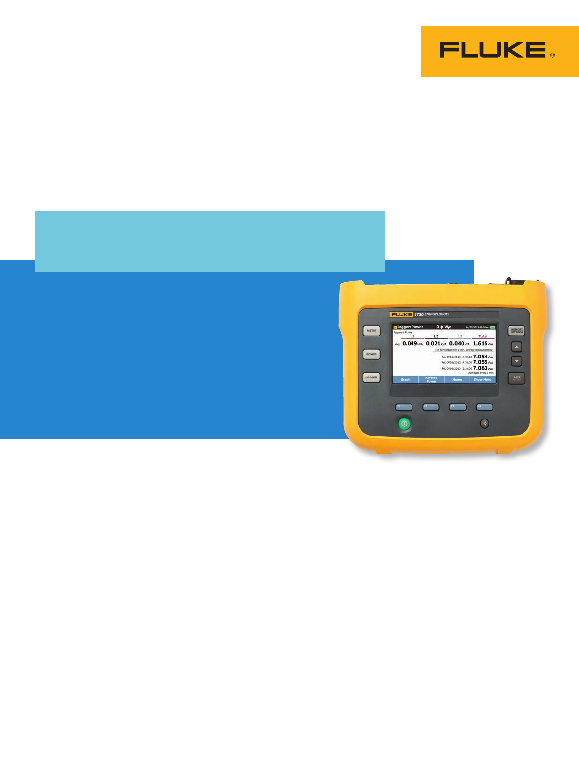
Fluke 1730
Three-Phase Electrical
Energy Logger
Energy logging is now within your reach—
discover where you’re wasting energy, optimize
your facility’s energy use and reduce your bill.
The new Fluke 1730 Three-Phase Electrical Energy logger
introduces a new simplicity to discovering sources of
electrical energy waste. Discover when and where
energy in your facility is being consumed; from the
service entrance to individual circuits. Profiling energy
usage across your facility helps you identify opportunities
for energy savings, and provides you with the data you
need to act on them. The new Energy Analyze software
package allows you to compare multiple data points over
time to build a complete picture of energy usage, which
is the first step to reduce the cost of your energy bill.
Technical Data
• Key measurements: voltage, current, power,
power factor and associated values enable
energy saving strategies to be implemented.
• Bright, color touch screen: perform conve-
nient in-the-field analysis and data checks
with full graphical display.
• Comprehensive logging: all measured values
are automatically logged and can be reviewed
during logging and before downloading for onthe-go analysis. More than 20 separate logging
sessions can be stored on the instrument.
• Optimized user interface: quick, guided,
graphical setup ensures you’re capturing the
right data every time, and the intelligent verification function indicates correct connections
have been made, reducing user uncertainty.
• Complete ‘in-the-field’ setup through the
front panel: no need to return to the workshop
for download and setup or to take a computer
to the electrical panel.
• Wide range power: power instrument directly
from the measured circuit eliminating the
need to find a power outlet while allowing the
instrument to be secured safely inside electrical panels.
• Two USB ports: one for PC connection and
another for fast, simple download to standard
USB thumb drives, or other USB devices.
• Compact size: designed to fit in tight spaces
and panels.
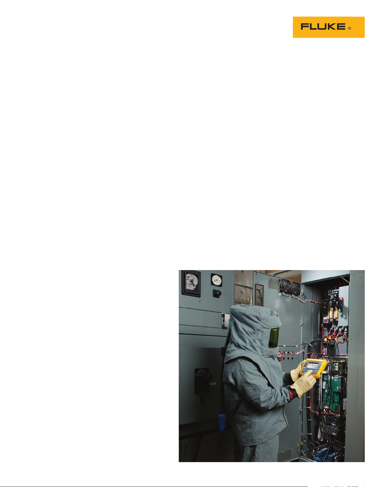
• Highest safety rating in the industry: 600 V
CAT IV/1000 V CAT III rated for use at the service entrance and downstream.
• Optimized measurement accessories: flat
voltage cable and thin flexible current probes
ensure easy installation even in tight spaces.
• Battery life: four-hour operating time (backup
time) per charge on lithium-ion battery.
• Security: safeguard against theft with a
Kensington lock.
• All new, Energy Analyze application soft-
ware: download, analyze and automated
reporting for a complete picture of energy
saving potential.
Page 2
Applications
Load studies
Discover how much energy individual pieces of
equipment are consuming when they are operating at minimum and maximum capacity. Check
capacity of circuits prior to adding additional
loads (various standards exist for this process;
in the US the NEC 220-87 is the recommended
standard). Load studies can also identify situations
where you may be exceeding the allowable load
on the circuit or when an agreed peak demand
applies from the utility. For convenience, some
load studies simply measure current which makes
installation of the measuring equipment quick and
easy. It is often recommended that load surveys
be performed for 30 days so that all typical load
conditions are encountered during the test.
Energy surveys
Users often ask where measurements should be
taken for an energy survey. The answer is multiple points within the facility. Start at the main
service feeders; compare the power and energy
measured here with the readings from the utility meter to ensure you’re receiving the correct
charges. Then move downstream to the larger
loads; these should be easy to identify by the current rating of the electrical panels downstream of
the service entrances. Measuring at many points
will allow a full picture of energy usage across
the facility to be developed. The next question users typically have is how long an energy
survey should last. This of course depends on the
facility, but it is recommended that you measure
for a period that matches a typical facility activity period. If the facility operates over a five day
work week with down time on the weekend, a
seven day survey will most likely capture typical
conditions. If the facility operates at a constant
level for 24 hours a day, 365 days a year, a single
day could be reasonably representative as long as
you avoid a period where there may be planned
maintenance.
To capture a full picture of the facilities energy
usage it is not necessarily required to have
measurements made simultaneously at every
consumption point in the facility. To get a comprehensive picture, spot measurements can be made
and then compared on a sliding time timescale.
For example, you could compare the service
entrance results from a typical Tuesday between
6:00 am and 12:00 pm with those of a larger load
in the facility. Typically there will be some correlation between these profiles.
Power and energy logging
When a piece of equipment is operated it instantaneously consumes a specific amount of power in
watts (W) or kilowatts (kW). This power is accumulated over the operating time and expressed as
energy consumed in kilowatt hours (kWh). Energy
is what your electric utility charges for; there will
be a standard charge from the utility per kilowatt
hour. Utilities may have other additional charges,
such as peak demand, which is the maximum
power demand over a defined period of time,
often 15 or 30 minutes. There may also be power
factor charges, which are based on the effects of
the inductive or capacitive loads in the facility.
Optimizing peak demand and power factor often
results in lower monthly electricity bills. The
1730 Three Phase Electrical Energy logger has
the capability to measure and characterize these
effects enabling you to analyze the results and
save money.
Simplified load studies
For situations where it’s either difficult or impractical to make a voltage connection the simple load
study feature allows users to perform a simplified
load study by measuring current only. The user
can enter the nominal expected voltage to create
a simulated power study. For accurate power
and energy studies it is required to monitor both
voltage and current but this simplified method is
useful in certain circumstances.
2 Fluke Corporation Fluke 1730 Three-Phase Electrical Energy Logger
Page 3

Specifications
Accuracy
Parameter Range Resolution Intrinsic Accuracy at Reference Conditions
Voltage 1000 V 0.1 V ± (0.2 % + 0.01 %)
150 A 0.1 A ± (1 % + 0.02 %)
150 0 A 1 A ± (1 % + 0.02 %)
300 A 1 A ± (1 % + 0.02 %)
3000 A 10 A ± (1 % + 0.02 %)
600 A 1 A ± (1.5 % + 0.03 %)
6000 A 10 A ± (1.5 % + 0.03 %)
4 A 1 mA ± (0.7 % + 0.02 %)
40 A 10 m A ± (0.7 % + 0.02 %)
Current:
Direct input
iFle x15 0 0 -12
iFlex3000-24
iFlex6000-36
i40s-EL clamp
Frequency 42.5 Hz to 69 Hz 0.01 H z ± (0.1 %)
Aux input ± 10 V dc 0.1 mV ± (0.2 % + 0.02 %)
Voltage Min/Max 1000 V 0.1 V ± (1 % + 0.1 %)
Current Min/Max defined by
accessory
defined by
accessory
Cosϕ/DPF 0 <= Cosϕ <=1 0.01 ± 0.025
Power factor 0 <= PF <=1 0.01 ± 0.025
THD on voltage 1000 % 0.1 % ± (2.5 % ± 0.05 %)
THD on current 1000 % 0.1 % ± (2.5 % ± 0.05 %)
(% of Reading + % of Full Scale)
± (5 % + 0.2 %)
Intrinsic uncertainty ± (% of reading + % of range)
Parameter Influence
quantity
Active power P PF ≥ 0.99 1.2 % +
0.5 <PF <0.99 1.2 % + 7 x
Apparent power S, S fund. 0 ≤ PF ≤ 1 1.2 % +
1
iFlex1500-12 iFlex3000-24 iFlex6000-36 i40s-EL
150A/1500A 300A/3000A 600/6000A 4A/40A
0.005 %
(1-PF)
+0.005 %
0.005 %
1.2 % +
0.0075 %
1.2 % + 7 x
(1-PF)
+ 0.0075 %
1.2 % +
0.0075 %
1.7 % +
0.0075 %
1.7 % + 7 x
(1-PF)
+ 0.0075 %
1.7 % +
0.0075 %
Reactive power N, Q fund. 0 ≤ PF ≤ 1 2.5 % of measured apparent power
Additional uncertainty in %
1
of range
1
Range = 1000 V x Irange
Reference conditions:
Environmental: 23 °C ± 5 °C, instrument operating for at least 30 minutes, no external electrical/magnetic field, RH <65 %
Input conditions: Cos
Current and power specifications: Input voltage 1 ph: 120 V/230 V or 3 ph wye/delta: 230 V/400 V
Input current: I > 10 % of Irange
Primary conductor of clamps or Rogowski coil in center position
Temperature coefficient: Add 0.1 x specified accuracy for each degree C above 28 °C or below 18 °C
ϕ/PF=1, Sinusoidal signal f=50 Hz/60 Hz, power supply 120 V/230 V ±10 %.
U >250 V 0.015 % 0.0225 % 0.0225 % 0.015 %
1.2 % +
0.005 %
1.2 % + 10 x
(1-PF)
+ 0.005 %
1.2 % +
0.005%
3 Fluke Corporation Fluke 1730 Three-Phase Electrical Energy Logger
Page 4

Electrical specifications
Power supply
Voltage range 100 V to 500 V using safety plug input when powering from the measurement
circuit
100 V to 240 V using standard power cord (IEC 60320 C7)
Power consumption Maximum 50 VA (max. 15 VA when powered using IEC 60320 input)
Efficiency ≥ 68.2 % (in accordance with energy efficiency regulations)
Maximum no-load consumption < 0.3 W only when powered using IEC 60320 input
Mains power frequency 50/60 Hz ± 15 %
Battery Li-ion 3.7 V, 9.25 Wh, customer-replaceable
On-battery runtime Four hours in standard operating mode, up to 5.5 hours in power saving mode
Charging time < 6 hours
Data acquisition
Resolution 16-bit synchronous sampling
Sampling frequency 5120 H z
Input signal frequency 50/60 Hz (42.5 to 69 Hz)
Circuit types 1-ϕ, 1-ϕ IT, Split phase, 3-ϕ delta, 3-ϕ wye, 3-ϕ wye IT, 3-ϕ wye balanced, 3-ϕ
Aron/Blondel (2-element delta), 3-ϕ delta open leg, Currents only (load studies)
THD THD for voltage and current is calculated using 25 harmonics
Averaging period User selectable: 1 sec, 5 sec, 10 sec, 30 sec, 1 min, 5 min, 10 min, 15 min, 30 min
Demand interval User selectable: 5 min, 10 min, 15 min, 20 min, 30 min
Data storage Internal flash memory (not user replaceable)
Memory size Typical 20 logging sessions of 10 weeks with 10-minute intervals
Logging period
Averaging period
Recommended
for 20 sessions
1
Logging Period
for 1 session
1 second 3 hours 2.5 days
5 seconds 15 ho u r s 12 days
10 seconds 28 hours 24 days
30 seconds 3.5 days 10 weeks
1 minute 7 days 20 weeks
5 minutes 5 weeks 2 years
10 m inutes 10 week s > 2 years
15 m i nute s 3.5 months > 2 years
30 minutes 7 months > 2 years
1
Interfaces
USB-A File transfer via USB flash drive, firmware updates
Max. current: 120 mA
USB-mini Data download device to PC
Extension port Accessories
Voltage inputs
Number of inputs 4 (3 phases and neutral)
Maximum input voltage 1000 V
, CF 1.7
rms
Input impedance 10 MΩ
Bandwidth (-3 dB) 2.5 kHz
Scaling 1:1, 10:1, 100:1, 1000:1 and variable
Measurement category 1000 V CAT III/600 V CAT IV
Current inputs
Number of inputs 3, mode selected automatically for attached sensor
Input voltage Clamp input: 500 mV
Rogowski coil input 150 mV
rms
/15 mV
/50 mV
rms
at 50 Hz, 180 mV
rms
; CF 2.8
rms
rms
/18 mV
at 60 Hz; CF 4; all at nominal
rms
probe range
Range 1 A to 150 A/10 A to 1500 A with thin iFlex flexible current probe, 12 inches
3 A to 300 A/30 A to 3000 A with thin Flex flexible current probe, 24 inches
6 A to 600 A/60 A to 6000 A with thin iFlex flexible current probe, 36 inches
40 mA to 4 A/0.4 A to 40 A with 40 A clamp i40s-EL
Bandwidth (-3 dB) 1.5 k H z
Scaling 1:1 and variable
1
The num ber of possible logging sessions and logging period depends on user requirements.
4 Fluke Corporation Fluke 1730 Three-Phase Electrical Energy Logger
Page 5

Auxiliary inputs
Number of inputs 2
Input range 0 to ± 10 V dc, 1 reading/s
Scale factor (available 2014) Format: kx + d user configurable
Displayed units (available 2014) User configurable (7 characters, for example, °C, psi, or m/s)
Environmental specifications
Operating temperature -10 °C to +50 °C (14 °F to 122 °F)
Storage temperature -20 °C to +60 °C (−4 °F to 140 °F)
Operating humidity 10 °C to 30 °C (50 °F to 86 °F) max. 95 % RH
30 °C to 40 °C (86 °F to 104 °F) max. 75 % RH
40 °C to 50 °C (104 °F to 122 °F) max. 45 % RH
Operating altitude 2000 m (up to 4000 m derate to 1000 V CAT II/600 V CAT III/300 V CAT IV)
Storage altitude 12,000 m
Enclosure IP50 in accordance with EN60529
Vibration MIL 28800E, Type 3, Class III, Style B
Safety IEC 61010-1: Overvoltage CAT IV, Measurement 1000 V CAT III/600 V CAT IV,
Pollution Degree 2
EMI, RFI, EMC EN 61326-1: Industrial
Electromagnetic compatibility Applies to use in Korea only. Class A Equipment (Industrial Broadcasting and
Communication Equipment)
Radio frequency emissions IEC CISPR 11: Group 1, Class A
Temperature coefficient 0.1 x accuracy specification/°C
General specifications
Color LCD display 4.3-inch active matrix TFT, 480 pixels x 272 pixels, resistive touch panel
Warranty 1730 and power supply: Two-years (battery not included)
Accessories: One-year
Calibration cycle: Two-years
Dimensions 1730: 19.8 cm x 16.7 cm x 5.5 cm (7.8 in x 6.6 in x 2.2 in)
Power supply: 13.0 cm x 13.0 cm x 4.5 cm (5.1 in x 5.1 in x 1.8 in)
1730 with power supply attached: 19.8 cm x 16.7 cm x 9 cm
(7.8 in x 6.6 in x 3.5 in)
Weight 1730: 1.1 kg (2.5 lb)
Power supply: 400 g (0.9 lb)
External protection Holster, Kensington lock slot
5 Fluke Corporation Fluke 1730 Three-Phase Electrical Energy Logger
Page 6

1500-12 iFlex Flexible Current Probe specifications
Measuring range 1 to 150 A ac / 10 to 1500 A ac
Nondestructive current 100 kA (50/60 Hz)
Intrinsic error at reference condition* ± 0.7 % of reading
Accuracy 1730 + iFlex ± (1 % of reading + 0.02 % of range)
Temperature coefficient over operating temperature range 0.05 % of reading/°C 0.09 % of reading/°F
Working voltage 1000 V CAT III, 600 V CAT IV
Probe cable length 305 mm (12 in)
Probe cable diameter 7.5 mm (0.3 in)
Minimum bending radius 38 mm (1.5 in)
Output cable length 2 m (6.6 ft)
Weight 115 g
Transducer cable material TPR
Coupling material POM + ABS/PC
Output cable TPR/PVC
Operating temperature -20 °C to +70 °C (-4 °F to 158 °F) temperature of conductor
Temperature, non-operating -40 °C to +80 °C (-40 °F to 176 °F)
Relative humidity, operating 15 % to 85 % non-condensing
IP rating IEC 60529:IP50
Warranty One-year
*Reference condition:
• Environmental: 23 °C ± 5 °C, no external electrical/magnetic field, RH 65 %
• Primary conductor in center position
under test shall not exceed 80 °C (176°F)
Ordering information
1730/BASIC Three-Phase Electrical Energy logger (excludes current probes).
1730/US Portable Energy Logger US version
1730/EU Portable Energy Logger EU version
1730/INTL Portable Energy Logger INTL version
Accessories
i1730-flex1500 iFlex flexible current probe 1500A 12 inch
i1730-flex3000 iFlex flexible current probe 3000A 24 inch
i1730-flex6000 iFlex flexible current probe 6000A 36 inch
i40s-EL i40s-EL Clamp-on Current Transformer
i1730-flex1500/3pk iFlex flexible current probe 1500A 12 inch, 3 pack
i1730-flex3000/3pk iFlex flexible current probe 3000A 24 inch, 3 pack
i1730-flex6000/3pk iFlex flexible current probe 6000A 36 inch, 3 pack
i40s-EL/3pk i40s-EL Clamp-on Current Transformer, 3 pack
1730-TL0.1M Test Lead Set; 1000 V CAT III, straight plug; 0.1 m; silicone; red/black
1730-TL2M Test Lead Set, 1000 V CAT III; straight plug; 2 m; PVC red/black
3PHVL-1730 Cable Assembly, Voltage Test Lead 3-Phase+N
C1730 1730 Soft Case
WC100 Color Localization Set
1730-Hanger Hanging strap
1730-Cable AUX input cable
Fluke. The Most Trusted Tools
in the World.
Fluke Corporation
PO Box 9090, Everett, WA 98206 U.S.A.
Fluke Europe B.V.
PO Box 1186, 5602 BD
Eindhoven, The Netherlands
For more information call:
In the U.S.A. (800) 443-5853 or
Fax (425) 446-5116
In Europe/M-East/Africa +31 (0) 40 2675 200 or
Fax +31 (0) 40 2675 222
In Canada (800)-36-FLUKE or
Fax (905) 890-6866
From other countries +1 (425) 446-5500 or
Fax +1 (425) 446-5116
Web access: http://www.fluke.com
©2013 Fluke Corporation.
Specifications subject to change without notice.
Printed in U.S.A. 8/2013 4314073B_EN
Pub ID: 12028-eng Rev. 01
Modification of this document is not permitted
without written permission from Fluke Corporation.
6 Fluke Corporation Fluke 1730 Three-Phase Electrical Energy Logger
 Loading...