

Page 1

KV 10
Installation Instructions 810656-00
GESTRA Outer Butterfly Valve
Page 2
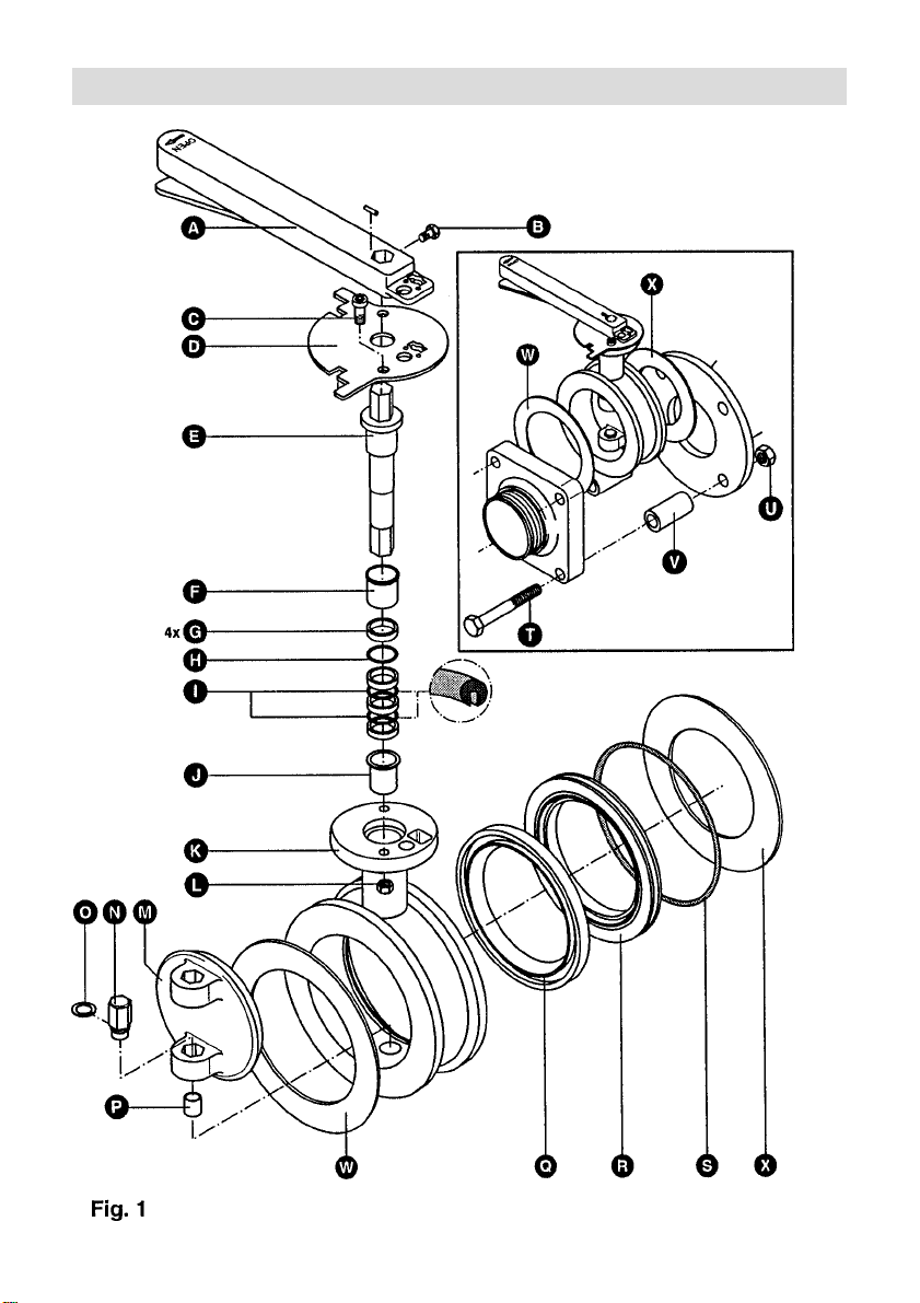
Parts Drawing
2
Page 3

Important Safety Note
Technical Data
Butterfly valves for tank containers must only
be installed by qualified staff.
Carefully read through installation instructions
before mounting the valve.
Use GESTRA genuine spare parts only.
Danger
Do not carry out any installation or
maintenance work unless the tank container
is completely empty and degassed.
Escaping vapours and gas can endanger life
and health of the person responsible for
installation and maintenance and cause
material damage.
Do not hold the device by means of the
operating lever.
Function
Butterfly valve (outer valve) with operating
lever for loading and unloading systems for
hazardous tank containers of IMO classes 1
and 2.
Opening:
Turn operating lever A anticlockwise through
90° and snap into position.
Closing:
Turn operating lever A clockwise through 90°
and snap into position.
Design
■ Main components:
Body for installation between flanges
Stem
Disc
Operating lever
Seat ring and gasket
■ Ancillary components:
Heating jacket
Hemisphere (as closure device)
Pressure/Temperature
Ratings
DN/NPS 80/3"
Service pressure [bar] 6
Min. service temp. [°C] –10
Max. service temp.[°C] 190
Test pressure [bar] 10
Connection
For dimensions and further specifications
see data sheet.
[psig] 87
[psig] 145
Waf er design for
installation between
flanges with
centering sleeve
Installation
Important Note
The disc must be in the closed position when
installing the valve.
Fitting (Fig. 1)
1. Introduce two hexagon-head bolts
through bottom holes of the square flange
and place guide sleeves V onto bolts.
2. Introduce now the bolts with sleeves T and
through bottom holes of the CV 10
V
flange and secure with two nuts U.
3. Place the closed butterfly valve type KV 10
onto the two guide sleeves.
4. Put gaskets W and X between the KV 10
guide sleeves V and flanges. The gaskets
must be flush with the valve.
5. Introduce hexagon-head bolt T through top
left hole of the square flange.
6. Introduce this bolt T through the
corresponding hole of the CV 10 flange and
secure with nut U.
7. Proceed in the same way with top right
hexagon-head bolt.
8. Align the valve KV 10 and tighten nuts
manually. Take care that the gaskets are
flush with the valve.
9. Tighten the hexagon-head bolts T and nuts
gradually and in diagonally opposite
U
pairs with a torque of 80 ± 5 Nm.
T
3
Page 4

Dismantling
For the remov al of the valve proceed
in reverse order.
Important Note
Do not damage gaskets during
installation.
Maintenance
The butterfly valve does not require any special
maintenance.
Important Note
Check main seal
of the fixing bolts T when inspecting the valve,
at least on the occasion of the “Inspection and
Examination” of the tank container which takes
place every 2½ years and whenever carrying
out maintenance or repair work.
Q
and the torque (80 ± 5 Nm)
Replacemente of disc
main seal
■ Main seal can be replaced without having to
extract the disc.
1. Remove the butterfly valve and the square
spigot outlet.
2. Remove seat ring R and seal Q from the
body.
3. Insert new seal, with the disc being in the
closed position.
Replacement of bearing bush and
stem sealing
4. Pull out stem E with the aid of operating
lever.
5. Remove bushes F + J and rings from
the stem guide.
6. Clean location hole for stem. Do not
damage the sealing surface for the
O-rings.
7. Insert new bushes J and F.
8. Apply a smear of lubricant to the new
O-rings I + H and ring G and push
them onto the stem. Consider correct order
and right position. Remove surplus
lubricant from the stem bearing surface.
9. Push stem E into stem guide.
10. Install notch plate D and operating lever
in reverse order.
11. Secure screw B (e. g. with the aid of
Loctite 222).
12. Re-establish wire seal so that you can see
if the valve has been tampered with.
Replacement of sleeve
and journal
1. Press retaining ring O out of the groove
and push towards the body.
2. Press journal N out of the body upwards
through disc lug by using the retaining ring
groove.
3. Pull bush P out of the body and insert new
bush.
4. Put retaining ring O onto bottom hexagon
lug and introduce journal N through the
hexagon socket disc lug.
5. Push journal completely into the body and
press retaining ring into the corresponding
groove.
Important Note
In order to remove the operating lever you must
destroy the wire seal between operating lever
and stem. There is a second seal between the
notch plate D and the body flange K. (Fig. 1)
1. Loosen screw B (secured with retainer,
e. g. Loctite 222) and remove operating lever
from stem.
2. Unscrew socket-head cap bolts C and lock
nuts L.
3. Remove notch plate D.
4
Page 5

Spare Parts
Item Designation Order No.
Disc 049 081
M
Main seal 048 870
Q
Seat ring 048 871
R
Retaining ring A 12 014 479
O
Collar bush 048 875
F
18 x 15 x 24
Collar bush 048 759
J
14 x 18 x 18
Bush 9.0 x 10 048 899
P
★SO-ring 049 345
★IO-ring 048 765
★HO-ring 048 766
Ring 048 767
G
Operating lev er incl. 048 878
A
notch plate and
assembly parts
Gasket 80 KV 10 048 887
W
Square spigot outlet 048 894
cpl.
Square spigot outlet 048 891
Assembly parts KV 10 048 888
★ ★
★ Parts subject to wear
★ ★
5
Page 6

GESTRA Gesellschaften · GESTRA Companies · Sociétés GESTRA · Sociedades Gestra · Società GESTRA
GESTRA Gesellschaften · GESTRA Companies · Sociétés GESTRA · Sociedades Gestra · Società GESTRA
Vertretungen weltweit · Agencies all over the world · Représentations dans le monde entier · Representaciones en todo el mundo · Agenzie in tutto il mondo
Vertretungen weltweit · Agencies all over the world · Représentations dans le monde entier · Representaciones en todo el mundo · Agenzie in tutto il mondo
España
España
GESTRA ESPAÑOLA S.A.
GESTRA ESPAÑOLA S.A.
Luis Cabrera, 86-88
Luis Cabrera, 86-88
E-28002 Madrid
E-28002 Madrid
Tel. (091) 5 152 032
Tel. 00 3491/5152032
Fax (091) 4 136 747; (091) 5 152036
Fa x0 0349 1/413674 7; 5152036
E-mail: gestra@gestra.es
E-mail: gestra@gestra.es
France Portugal
France Portugal
Invensys Flow Control
Flowserve Flow Control S.A.S.
France SAS
10 Avenue du Centaure, BP 8263
10 Avenue du Centaure, BP 8263
F-95801 CERGY PONTOISE CEDEX
F-95801 CERGY PONTOISE
Tél. 003 31/34432660
Tél. (01) 34.43.26.60
Fax 00331/34432687
Fax (01) 34.43.26.87
E-mail: gnation@flowserve.com
E-mail: gnation@gestra.fr
Italia
Italia
Invensys Flow Control Division
Italgestra S.r.l.
Italgestra S.r.l.
Via Carducci 125
Via Carducci 125
l-20099 Sesto San Giovanni (MI)
l-20099 S.S. Giovanni (MI)
Tel. 003902 /2410 12.1
Tel. (02) 24 10 12 1
Fax 0039 02/24 1012.460
Fax (02) 24 10 12460
E-mail: info@italgestra.it
E-mail: info@italgestra.it
Polska
Polska
GESTRA POLONIA Spolka zo.o.
GESTRA POLONIA Spolka z o. o.
Ul. Schuberta 104
Ul. Schuberta 104, P.O. Box 71
PL-80-172 Gdansk
PL-80-172 Gdansk
Tel. (058) 306 10 02
Tel. 004858/3061002 oder 306 1010
Fax (058) 306 10 03
Fax 0048 58/3061003 oder 3063300
E-mail: gestra@gestra.pl
E-mail: gestra@gestra.pl
GESTRA PORTUGUESA VALVULAS LDA.
GESTRA PORTUGUESA VALVULAS LD A.
Av. Dr. Antunes Guimarães, 1159
Av. Dr. Antunes Guimarães, 1159
P-4100 Porto
Porto 4100-082
Tel. (022) 6 1987 70
Tel. 0035122/6 198770
Fax (022) 6 1075 75
Fax 00351 22/6107575
E-mail: gestra@gestra.pt
E-mail: gestra@gestra.pt
®
®
GESTRA GmbH
GESTRA GmbH
Postfach 10 54 60
Postfach 10 5460
D-28054 Bremen
D-28054 Bremen
Hemmstraße 130
Münchener Str. 77
D-28215 Bremen
D-28215 Bremen
Tel. +49 (0) 421 3503-0
Tel. +49 (0) 421 35 03- 0
Fax+49 (0) 421 3503-393
Fax +49 (0) 421 35 03- 393
E-mail
gestra.gmbh@gestra.de
E-mail
gestra.gmbh@gestra.de
Internet www.gestra.de
Internet www.gestra.de
A Unit of Flowserve Corporation
An Invensys company
810656-00/401c · ©2000 GESTRA GmbH · Bremen · Printed in Germany
 Loading...