

Page 1
Worcester Actuation Systems
1. Description
The I-75 Interface is designed to be used and mounted in the Series
75 Actuator as one of many standard options. Function of the I-75
Interface is to allow the Series 75 Actuator to be powered by a 120 or
240 VAC power supply, operated directly by any programmable
controller, microprocessor, and/or computer regardless of the output
rating of these devices. Depending on the control input to be used,
there are several options of the I-75 Interface:
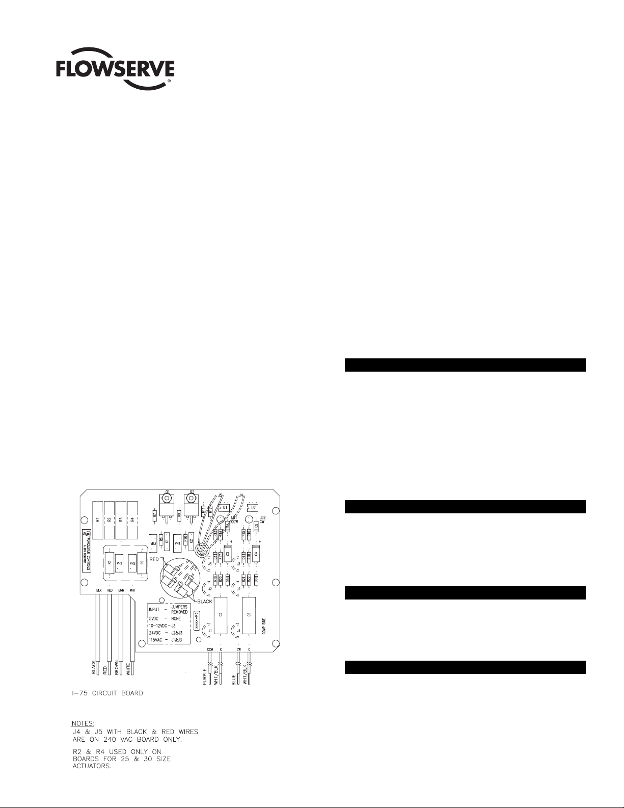
These options are identified by the nameplate on the circuit board.
5V for 5 VDC input
XV for 12 VDC input
XX for 24 VDC input
15 for 120 VAC input
2. Installation of I-75 Interface Board into
Series 75 Electric Actuator
2.1 Check Kit for Parts:
Common Parts for Sizes 10-30 Actuators
Qty. Name
1 Circuit Board Subassembly
1 Insulating Board
5-6 Washers (Nylon)
5-6 Grommets (Rubber)
5-6 Mounting Screws
5 Cable Ties
1 Wiring Label
1 Closed-End Splice
1 Wire - White
Additional Parts for Sizes 10-23 Actuators
Qty. Name
1 Bracket - Right
1 Bracket - Left
2 Spacer (Bracket)
2 Mounting Screw (Spacer/Bracket)
Additional Parts for 240 VAC Option
Qty. Name
2 Limit Switch
1 Lead Assembly - Gray
1 Lead Assembly - Blue
Additional Parts for Sizes 25, 30 Actuators
Qty. Name
1 Mounting Bracket
2 Mounting Screw (Bracket)
Tools needed for assembly:
1
/
4" Nut Driver,
1
/
8" Screwdriver and Needle Nose Pliers.
FCD WCAIM2000-00
(Part 06094)
I-75 Interface
Installation, Operation and Maintenance Instructions
Figure 1
Page 2
2
Flow Control
Worcester Actuation Systems
2.2 Assembly Procedure
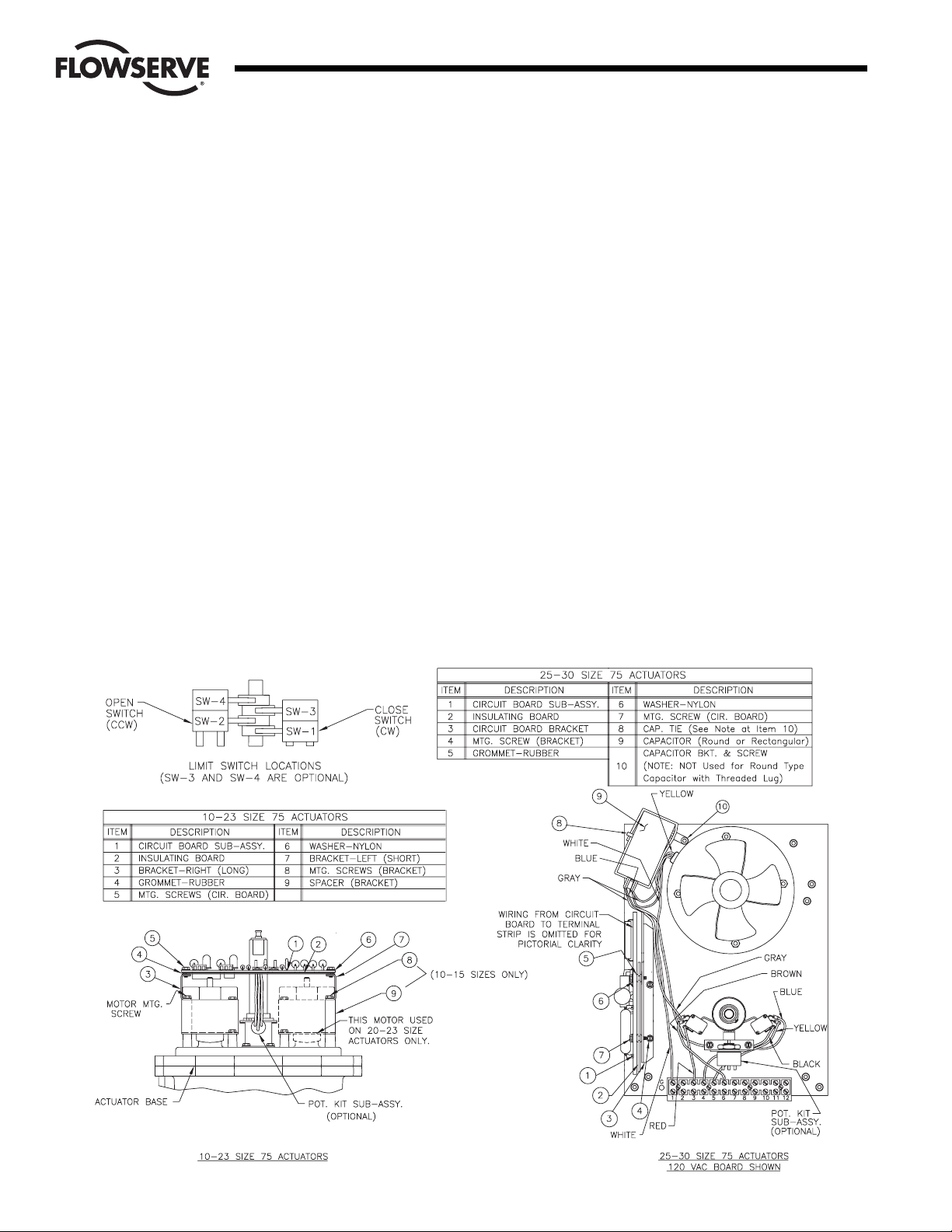
2.2.1 For 10-23 Size Electric Actuators (See Figure 2):
A. Pre-tap circuit board bracket holes with the self-tapping
screws. Mount these brackets to the actuator motors or
spacers as provided. The longer bracket is mounted to the
right side of the actuator when facing the terminal strip. Use
the motor mounting screws.
B. Remove and replace motor screws carefully to avoid stripping
the threads of these self-tapping screws.
C. Once these motor screws and brackets are firmly secured,
firmly tap the motor stator to ensure realignment of the top
motor bearing.
D. Loosen all terminal strip screws to connect the circuit board
wiring to the actuator terminal strip. See Section 3 for proper
wiring of circuit board to the actuator terminal strip. Wire
routing is important. Ensure that wiring is not pinched and is
not near cams or mechanical brake (if used).
E. Assemble circuit board into actuator. Slide rubber grommets
onto insulating board. Put nylon washers under heads of selftapping screws.
F. Put circuit board onto brackets. Fasten board to brackets
loosely using mounting screws. Use a nylon washer and a
rubber grommet under the self-tapping screw mounted on the
right side of board when facing terminal strip.
G. Snug down the circuit board and firmly secure mounting
screws.
2.2.2 For 25 and 30 Size Electric Actuators (See Figure 2):
A. Assemble circuit board to bracket as shown.
B. Place four of the rubber grommets onto the insulating board.
Put nylon washers on the screws and place screws through
the circuit board and insulation board. Start screws into the
bracket.
C. Where no insulation board is used, place a rubber grommet
between the board and the bracket. Firmly tighten all screws.
D. Use two screws to fasten circuit board bracket to the motor
mounting plate. Component side of the board is facing out.
Figure 2
Page 3

3
Flow Control
Worcester Actuation Systems
3. Wiring
3.1 External Power - 120/240 VAC Option (Figures 3 and 4):
NOTE: All wiring to terminal strip should be inserted only to mid-point
of terminal strip.
AC power connections are made to terminals 1 and 2 of the terminal
strip. The AC neutral, or common, wire should be connected to
terminal 1 and the AC “HOT” wire to terminal 2. Grounding wire
should be connected to green colored grounding screw (if present) on
actuator base or to any base plate mounting screw in the actuator.
Signal and power wiring for an actuator may be run for short
distances in the same conduit.
See table below for minimum fuse rating when overcurrent protection
is used in motor power circuit.
Minimum Fuse Rating for Overcurrent Protection
Actuator Size Voltage Fuse Rating
10-23 120 VAC 5 A
25/30 120 VAC 10 A
10-23 240 VAC 3 A
25/30 240 VAC 5 A
NOTE: The table shows the minimum rating to prevent inrush current
from blowing the fuse.
3.2 External Input Signal Connections - 120/240 VAC Option
(Figures 3 and 4):
There are two isolated inputs, one for counterclockwise (CCW); the
other for clockwise (CW) directions. CCW input positive (more
positive) or hot (in case of AC) is connected to terminal 10, CW input
positive (more positive) or hot (in case of AC) is connected to
terminal 12. Other input wires, negative (less positive) or common
(in case of AC) for CCW and CW directions are connected to
terminals 9 and 11 respectively. For complete wiring diagram see
Figures 3 or 4 below, or wiring label which is to be attached to inside
of actuator cover.
3.3 Internal Wiring - Common to 120/240 VAC Options
(Figures 3 and 4):
NOTE: When there are multiple wires going to terminal 1, use the
short white wire included in kit. Connect it to terminal 1 and then
splice it to the other white wires (common) using the closed-end
splice.
From the circuit board connect white wire to the back of terminal 1,
brown wire to the back of terminal 2, red wire to the front of terminal
3, and black wire to the front of terminal 4. Connect white/black
(input common) wires of CCW and CW to back of terminals 9 and 11
respectively.
3.3.1 PC Board - 120 VAC (Figure 3):
Connect purple wire of CCW input to back of terminal 10, and
blue wire of CW input to back of terminal 12.
Figure 3 Figure 4
Page 4

3.3.2 PC Board - 240 VAC (Figure 4):
For I-75, 240 VAC option only, the limit switches (SW-1, SW-2)
are used to interrupt CW, CCW input signals, therefore the wiring
will be different.
Connect purple wire of CCW input to back of terminal 10, and
blue wire of CW input to back of terminal 12.
If the installed switches SW-1, SW-2 are wired per standard
wiring, remove the brown, red, yellow, and black wires from the
limit switches and the internal side of terminal strip. Remove the
original #18 gauge gray and blue wires from capacitor to switches
(make a note of which wire is on which capacitor terminal) and
discard. Replace with new #18 gauge gray and blue wires from
Interface Kit and connect the gray wire to the capacitor and to
terminal 3 and the longer blue wire to the capacitor and to
terminal 4.
The two black wires (#20 gauge) from the Interface board
connect to the common and normally closed contacts of switch
no. 1 (lower right-hand switch), and the two red wires (#20
gauge) from the Interface board connect to the common and
normally closed contacts of switch no. 2 (lower left-hand switch).
Route the wires so they will not interfere with switch, or feedback
pot operation, if used.
Securely tighten terminal screws. Keep wiring away from all
rotating parts and secure with cable ties.
3.4 Wiring Different Options:
If Series 75 actuator is equipped with I-75 Interface and additional
option has to be added, wire the additional option per instructions
included in the option kit. If there are no available locations on
terminal strip for wiring option, relocate wires accordingly and always
mark the change on wiring diagram inside the cover. If the terminal
strip is full, the connections have to be hard-wired using splices.
4. Indication and Repair
(Use Figure 1 for component location.)
LED Indicators - Light emitting diodes marked LD1, LD2 are in input
circuits and indicate what particular input is on. Right LED, LD2,
indicates that CW, close, signal is on. Left LED, LD1, indicates that
CCW, open, signal is on.
If a malfunction occurs, look for the following:
If particular input is energized and corresponding LED light is not on,
check for component damage or other continuity disruption in
corresponding CCW and/or CW input circuit. If everything appears to
be OK, replace matching opto-coupler U2 or U1.
Input circuit is OK. LED is lighted and actuator is not running. If
components and continuity in corresponding power circuit are alright,
then failed component is triac Q2 or Q1 depending which way the
actuator doesn’t run, CCW or CW.
If the actuator doesn’t run in either direction, it is likely that the
actuator is defective. To check this, remove the red and black leads
from terminals 3 and 4 of the actuator (coming from Interface board)
and the AC line connections from terminals 1 and 2. Tape these leads.
Using a test cable, apply power to actuator terminals 1 and 3. The
120 VAC actuator only (see note below) should rotate CCW until
stopped by the CCW limit switch. Then apply power to terminals 1
and 4 to check CW 120 VAC actuator and the CW limit switch. If the
actuator does not operate, check 120 VAC associated wiring, terminal
strip, the limit switches, motor and capacitor. Check switch continuity.
Check for an open motor winding, and check for a shorted capacitor.
If the problem in the actuator still cannot be determined, return the
unit for service. If the actuator functions properly, the problem is in
the interface board.
NOTE: The limit switches for the 240 VAC I-75 actuator do not control
the motor circuit, they control input circuit only. When applying power
to terminals 1 & 3, and 1 & 4 to check CCW, CW rotations, do this
momentarily so that you do not override 0-90° quadrant.
Request RMA (Return Material Authorization) number from the
factory, replace defective board, and return it to the factory with
proper description of problem and application.
Flow Control
Worcester Actuation Systems
Flowserve Corporation has established industry leadership in the design and manufacture of its products. When properly selected, this Flowserve product is designed to perform its intended function
safely during its useful life. However, the purchaser or user of Flowserve products should be aware that Flowserve products might be used in numerous applications under a wide variety of industrial
service conditions. Although Flowserve can (and often does) provide general guidelines, it cannot provide specific data and warnings for all possible applications. The purchaser/user must therefore
assume the ultimate responsibility for the proper sizing and selection, installation, operation, and maintenance of Flowserve products. The purchaser/user should read and understand the Installation
Operation Maintenance (IOM) instructions included with the product, and train its employees and contractors in the safe use of Flowserve products in connection with the specific application.
While the information and specifications contained in this literature are believed to be accurate, they are supplied for informative purposes only and should not be considered certified or as a guarantee of
satisfactory results by reliance thereon. Nothing contained herein is to be construed as a warranty or guarantee, express or implied, regarding any matter with respect to this product. Because Flowserve
is continually improving and upgrading its product design, the specifications, dimensions and information contained herein are subject to change without notice. Should any question arise concerning
these provisions, the purchaser/user should contact Flowserve Corporation at any one of its worldwide operations or offices.
For more information about Flowserve Corporation, visitt www.flowserve.com or call USA 1 800 225 6989.
FLOWSERVE CORPORATION
Flow Control
Worcester Actuation Systems
5114 Woodall Road
P.O. Box 11318
Lynchburg, VA 24506-1318
Phone (434) 528-4400
Fax (434) 845-9736
www.flowserve.com
© 2004 Flowserve Corporation, Irving, Texas, USA. Flowserve and Worcester Controls are registered trademarks of Flowserve Corporation. FCD WCAIM2000-00 Printed in USA.
(Part 06094)
 Loading...