

Page 1

GESTRA Steam Systems
HV 215
Installation Instructions 818480-01
Hydraulic Loading and Unloading System HV 215
t
1
Page 2

Contents
Page
Important Notes
Usage for the intended purpose .................................................................................................................................. 8
Safety notes ............................................................................................................................................................... 8
Danger .......................................................................................................................................................................8
Legal regulations ........................................................................................................................................................ 9
Explanatory Notes
Scope of supply ........................................................................................................................................................10
Description ............................................................................................................................................................... 10
Function ...................................................................................................................................................................11
Technical data .................................................................................................................................................... 11, 12
Fluid list .............................................................................................................................................................. 13, 14
Installation
Hydraulic loading & unloading system HV 215 .......................................................................................................... 15
Mounting flange .................................................................................................................................................. 15, 16
Bottom valve HWV 205/1 - DN 80 ......................................................................................................................17 - 19
Bottom valve HWV 215/1 - DN 80 ......................................................................................................................20 - 23
Cable routing ............................................................................................................................................................24
Operating device BV 110 .......................................................................................................................................... 25
Connecting lines ................................................................................................................................................. 26, 28
Attaching operating plates HV 215 ............................................................................................................................29
Attaching list indicating fluids ................................................................................................................................... 29
Filling and venting of hydraulic system ...................................................................................................................... 30
Filling and venting of hydraulic actuating system ...................................................................................................... 30
Filling and venting of hydraulic indicating system...................................................................................................... 31
Performance test ...................................................................................................................................................... 31
Operation
Service ..................................................................................................................................................................... 32
Emergency operation ................................................................................................................................................ 33
Maintenance
Bottom valves HWV 205/1 - DN 80 / HWV 215/1 - DN 80 .......................................................................................... 34
Operating device BV 110 ...........................................................................................................................................35
Connecting lines ....................................................................................................................................................... 35
2
Page 3

Contents – continued –
Page
Servicing
Hydraulic loading & unloading system HV 215 .......................................................................................................... 36
Replacing valve plug seal ...................................................................................................................................36 - 38
Reworking seat flange .............................................................................................................................................. 39
Replacing gaskets of actuacting cylinder ............................................................................................................ 40, 41
Replacing control unit of bottom valve ......................................................................................................................42
3
Page 4
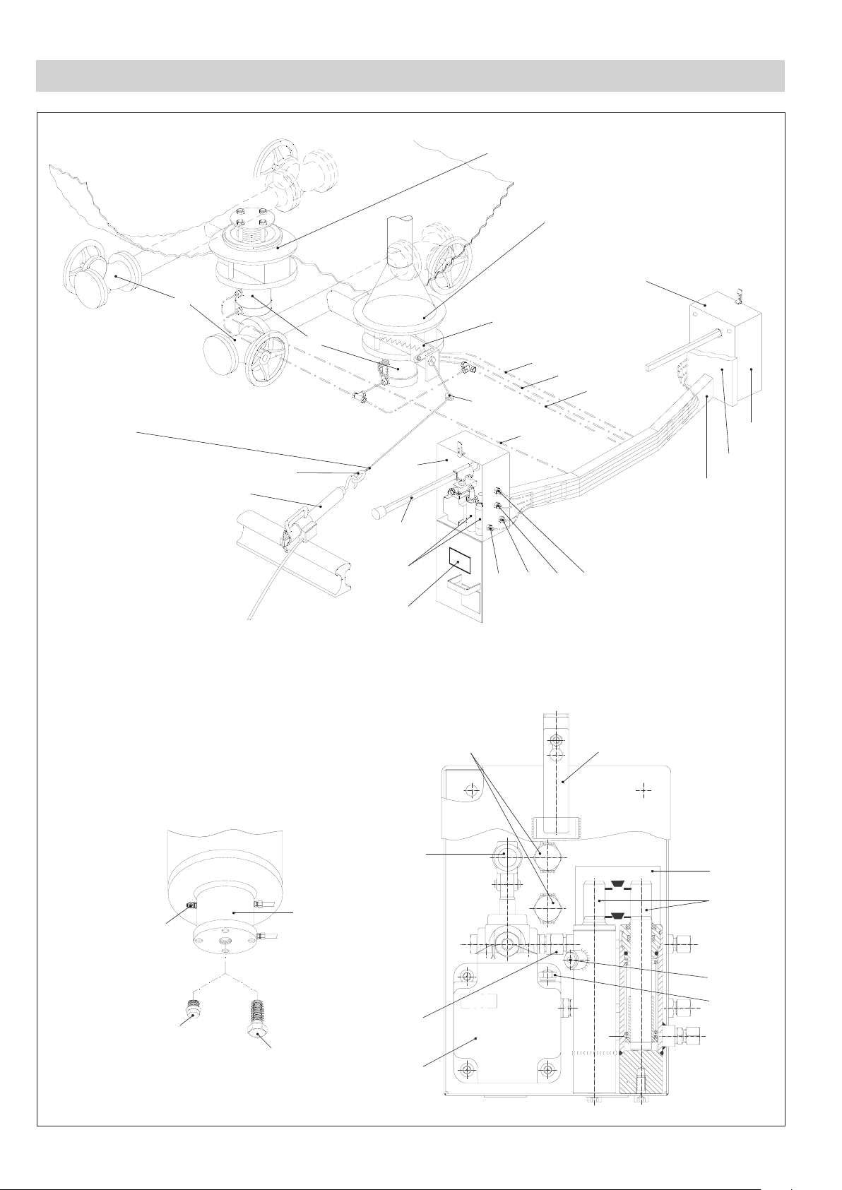
Components
F
Y
S
K
Tension rope with
wire cable clamp
A
B
HWV 205/1
X
Y
G
L
HWV 215/1
BV 110
R
P
E
C
D
E
W
V
F
H
L G R P
Z
K
M
F
gas phase liquid phaseopen
N
B
closed
O
I
Q
S
U
J
K
T
4
Page 5

Key
A Shut-off valves
B Actuating cylinder
C Rail hook
D Ring
E Operating devices
F Pump lever of hydraulic hand pump
G Line leading to the indicating cylinder of the gas phase
H Indicating cylinder
I Filling connection
J Sealing plug
K Screw for sealing off opening for emergency unloading
L Line leading to the indicating cylinder of the liquid phase
M Bolt for operating device
N Plate showing valve position of indicating pistons
O Indicating pistons
P Pressure line
Q Screw-in plug for venting facility
R Return line
S Screw for oil filling connection (with dip stick)
T Hydraulic hand pump
U Non-return valve
V Transverse pipe-run
W Frame
X Control unit
Y Guide bushing
Z Fluid list
5
Page 6

Basic Components of Bottom Valves
Mounting flange
Valve head
Body
1
2
3
4
5
6
7
8
31
j i h g
f
e
d
c
b
Actuating cylinder
6
9
0
!
"
§
$
a
=
)
(
/
&%
Page 7

Key
1 Hexagon head cap screw
2 Locking washer
3 Spring plate
4 Stay bolt
5 Sleeve
6 Gasket
7 Seat flange
8 Gasket
9 Push rod
0 Bellows
! Gasket
" Piston
§ Piston seal
$ Hexagon head cap screw
% Sealing plug
& Joint ring
/ Retaining ring
( O-ring
) O-ring
= Bushing
a Seal ring
b Hexagon head cap screw
c Socket-head cap screw
d Locking washer
e Valve plug
f Compression spring
g Washer
h Retaining ring
i Socket-head cap screw
j Washer
31
Valve plug seal
7
Page 8

Important Notes
Usage for the intended purpose
The hydraulically operated loading and unloading system HV 215 is intended solely for filling and draining stationary
and mobile tanks containing pressure liquefied gases.
Its use is permissible only within the allowable pressure and temperature ratings and only if the chemical and
corrosive influences on the equipment are taken into account. Before installing the equipment make sure that the
loading & unloading system is suitable for the intended application and the fluid to be used (corrosion resistance
and chemical suitability).
Modifications to the design may only be made if the manufacturer‘s written permission is obtained.
Any type of use differing from the usage described above must be considered as improper. The resulting risk will
have to be borne by the user alone. The manufacturer hereby expressly rejects any claims for any resulting damage.
The use of external pumps for opening or closing the bottom valves is not permitted.
Safety notes
The loading and unloading system must not be installed or commissioned by anyone other than qualified staff.
Maintenance and service work must only be performed by adequately trained persons who have a recognised
level of competence.
For installation, removal, commissioning, operation and maintenance, every person who works with the loading and
unloading system must have read and understood the complete installation manual. Furthermore, responsibilities
must have been defined clearly and unambiguously and must be adhered to.
The operating company must ensure that, whenever the loading and unloading system is being operated, it is in
perfect condition.
Attention
Working methods that jeopardise safety must not be used!
Danger
If the loading and unloading system is used in an inexpert or improper manner by unqualified staff, it can cause
danger to life and limb for the user or for third parties, possibly resulting in death.
During operation, the bottom valves of the loaded and unloaded tanks are under pressure. During the loading and
unloading procedure all other components are also under pressure. In this condition, screws as well as nuts and
bolts of the loading and unloading system must not be slackened. Liquid or vaporizing fluids might escape and
could cause severe cases of poisoning and environmental pollution.
During the loading and unloading procedure do not leave the installation unattended.
The shut-off valves might be cold during the loading and unloading procedure. Make sure that the operator wears
protective gloves when operating the handwheels.
Any installation or removal work may only be performed when the tank is at zero pressure and completely free of gas.
When carrying out installation and maintenance work, make sure that the tank cannot be operated accidentally.
8
Page 9

Important Notes – continued –
Warning
Any use of naked flames is expressly forbidden!
Before perfomring any service work inside the tank make sure that the tank is sufficiently ventilated
and all gases have been completely vented. The rules concerning MAC (= maximum allowable
concentration) values at place of work must be strictly applied!
Legal regulations
The configuration of the loading and unloading system HV 215 mounted to the tank car carrying pressurized
gas meets the requirements of DIN 26026 or of EN 12561-3.
The bottom valves HWV 205/1- DN 80 and HWV 215/1- DN 80 fulfill the legal requirements of the RID / GGVSE section 6, constituting the first inner shut-off as defined in these regulations.
9
Page 10

Explanatory Notes
Scope of supply
1 Bottom valve HWV 205/1 - DN 80
1 Bottom valve HWV 215/1 - DN 80 with tension rope
2 Hydraulic operating devices BV 110
2 Operating plates HV 215
2 Plates indicating fluids (only for bottom valves with valve plug seal made of CR)
1 Installation manual for loading & unloading system HV 215
1 Set of acceptance certificates
The following items are not scope of the supply but can be ordered separately:
1 Set of connecting lines as accessory kit
4 Shut-off valves DN 80
2 Valve mounting flanges
Description
The hydraulically operated loading and unloading system HV 215 is designed for filling and draining stationary
and mobile tanks containing pressure liquefied gases.
It is mainly used in tank cars carrying pressurized gases. These tank cars (TC) require a high degree of reliability,
ease of operation and maintenance and a long service life of the associated valves.
The loading and unloading system consists of the two rapid-action bottom valves, the two operating devices, the
shut-off valves, the rail hook and the tension rope. The connecting lines required for operating the loading and
unloading system are either made of hydraulic tubes and hydraulic hoses or entirely of hydraulic hoses.
The bottom valves type HWV 205/1 - DN 80 and type HWV 215/1 - DN 80 (with control unit) are designed for
installation in the valve-mounting flanges located at the bottom of the vessel. Both bottom valves are always
opened or closed together. A manifold connects the bottom valves directly with the shut-off valves. Both valves
can either be used for the liquid phase or the gas phase.
The operating devices consist of a hydraulic hand pump and one indicating piston for the liquid phase and one
for the gas phase. They are attached to the left and right hand side of the tank car, which means that the bottom
valves can be opened from either side of the tank car by actuating the respective operating device.
During the loading/unloading process the rail hook connected to the tension rope keeps the bottom valves in the
open position. In the event of an emergency, e. g. emergency shut-off or inadvertent moving of the tank car, the
rail hook is disengaged from the rail and the bottom valves close instantaneously (rapid-action closing).
10
Page 11
Explanatory Notes – continued –
TÜ. AGG.
Manu.-no.:
P
test
: 37.5bar
T
min.
: - 50°C valve plug seal PTFE
T
min.
: - 40°C valve plug seal CR
GESTRA HWV
MADE BY GESTRA
Function
The loading and unloading system HV 215 is designed for filling and draining tanks that contain pressureliquefied gases.
One bottom valve opens for the liquid phase and the other opens for the gas phase. Both opening processes
always take place simultaneously.
The operating device of the tension rope (e. g. rail hook VZ 10) engaged to one of the rails provides the required
tension of the rope. This tension keeps the ball valve of the control unit of the hydraulic system closed.
The hydraulic hand pump of the operating device BV 110 can then be used to apply pressure to the hydraulic
system. The pressure acts on the actuating cylinders of the bottom valves, forcing the piston to go up and thereby
causing the bottom valves to open.
The current lift position of both bottom valves is indicated separately by the indicating cylinders of the operating
device BV 110.
When the rail hook is disengaged, i. e. when the load on the tension rope is reduced, the hydraulic system opens,
leading to the rapid-action closing of the bottom valves within less than 1 second.
The non-return valve integrated in the operating device BV 110 prevents the premature closing of the bottom
valves caused by leaking fluids in the hydraulic hand pump and the pressure-reducing valve.
Technical data
Attention
For pressure / temperature ratings of the bottom valves see name plate.
Name plate drawing
Name plate specifications
Type of bottom valve
Type approval
GESTRA manufacturing no.
Test pressure
Type of valve plug seal used
in valve head
11
Page 12
Explanatory Notes – continued –
Technical data – continued –
Pressure/Temperature Ratings of Bottom Valves
Nominal pressure PN [bar]
Test pressure [bar]
Temperature range for valve plug seal CR [°C] – 40 to + 50
Temperature range for valve plug seal PTFE [°C] – 50 to + 50
Connection of bottom valve body
Spring pressure on valve plug [N] 322 ± 30
Lift of valve plug [mm] > 21.2
Drag coefficient
ζ
Item no. Component Material
– Body 1.0566
b
$
Hexagon head cap screw M16 A2-70 or A4-70
Hexagon head cap screw M12 A2-70
Socket-weld ends for manifold
with O. D. 88.9 mm
Loading Unloading
3.3 2.8
25
37.5
7
e
f
3
4
0
68!
31
c
()
5
Weight [kg] HWV 205/1 HWV 215/1 BV 110
Body 20 20 –
Valve head
Seat flange 1.4571
Valve plug 1.4571
Compression spring 1.4310
Spring plate 1.4301
Stay bolt 1.4301
Bellows, complete 1.4541 and 1.4571
Gasket PTFE
Valve plug seal PTFE or CR
Socket-head cap screw A2-70
O-ring NBR 70 Shore
Sleeve 1.4313
9 9 –
Hydraulic actuator
Control unit
Total 36 39 2 x 16
12
7 7 –
– 3 –
Page 13

Explanatory Notes – continued –
Fluid list
Media Class
Propane 2 2F 1978 X X
Butane 2 2F 1011 X X
Propene 2 2F 1077 X X
Butene-1
Butadiene-1.3
Ammonia 2 2TC 1005 X X
Ethyl chloride
Methyl chloride
Vinyl chloride
Gas R12
Gas R21
Gas R22
Classification
code
2 2F 1012 X X
2 2F 1010 X X
2 2F 1037 X
2 2F 1063 X
2 2F 1086 X
2 2A 1028 X
2 2A 1029 X
2 2A 1018 X
UN No.
Valve plug seal
PTFE down to
-50 °C
Valve plug
seal CR down
to
Gas R114
Gas R115
Gas R12 B1
Methyl bromide
Methylamine (free from water)
Dimethylamine (free from water)
Trimethylamine (free from water)
Ethylamine (free from water)
Hexafluoropropylene R1216
Dimethyl ether
Chlorotrifluoroethane R133a
Ethylene oxide with
max. 10% carbon dioxide
Ethylene oxide with
nitrogen up to 10 bar at 50 °C
2 2A 1958 X
2 2A 1020 X
2 2A 1974 X
2 2T 1062 X
2 2F 1061 X
2 2F 1032 X
2 2F 1083 X
2 2F 1036 X
2 2A 1858 X
2 2F 1033 X
2 2A 1983 X
2 2TF 1040 X
2 2TF 1040 X
Mixture F1
Mixture F2
Mixture P1
2 2A 1078 X
2 2A 1078 X
2 2F 1060 X
13
Page 14

Explanatory Notes – continued –
Fluid list – continued –
Media Class
Mixture A (trade name butane)
Mixture AO (trade name butane)
Mixture A1
Mixture B
Mixture C (trade name propane)
Mixtures of hydrocarbons with
butadiene -1.3
Iso butane
Iso butene
Cis -2-butene
Trans -2-butene
Cyclopropane 2 2F 1027 X
Classification
code
2 2F 1965 X X
2 2F 1965 X X
2 2F 1965 X X
2 2F 1965 X X
2 2F 1965 X X
2 2F 1010 X X
2 2F 1969 X
2 2F 1055 X
2 2F 1012 X X
2 2F 1012 X X
UN No.
Valve plug seal
PTFE down to
-50 °C
Valve plug
seal CR down
to
Gas mixture R500
Gas mixture R502
Carbon dioxide
Ethylene 2 3F 1038 X
2 2A 2602 X
2 2A 1973 X
2 3A 2187 X
14
Page 15

Installation
Hydraulic loading & unloading system HV 215
We highly recommend that only qualified staff should carry out installation work in accordance with these
installation instructions. The manufacturer expressly rejects any claims for damage caused by improper installation.
All parts to be fitted must meet the technical requirements specified by the manufacturer. All genuine parts are
guaranteed to comply with these requirements.
For installation work choose lifting devices that are specified for the respective weights. Use only suitable and
proper lifting devices.
When welding observe legal regulations and in-house guidelines concerning welded connections. Before welding
clean all spots to be welded.
Make sure that the gaskets of the flanged connections are exactly placed between the flanges. Clean all seating
surfaces before installing the equipment.
Before installing the valves remove the transport packing and all transit protection plugs for end connections.
Install the equipment in the following order:
n Mounting flanges
n Bottom valve HWV 205/1 - DN 80
n Bottom valve HWV 215/1 - DN 80
n Cable routing
n Operating devices BV 110
n Connecting lines
n Attaching operating plates HV 215
n Attaching plates indicating fluids
Mounting flange
The mounting flanges for bottom valves type HWV 205/1 - DN 80 and HWV 215/1 - DN 80 have the same
form and can be installed in the same way.
They are not scope of supply of the loading & unloading system HV 215 but can be ordered from Gestra.
Valve mounting flanges made from the following materials are available:
n P355NL1 (1.0566, old: TStE 355)
n S420NL (1.8912, old: TStE 420)
n P460NL1 (1.8915, old: TStE 460)
Further materials are available on request.
Gestra supplies valve mounting flanges with a standard diameter of 430
+6
mm. To avoid a wall thickness
misalignment between the valve mounting flange and the tank wall, adjust the outside diameter D to the
thickness S of the tank car (see drawing on page 16). Make sure that the weld joint produced is in compliance
with the specifications of the tank manufacturer.
The valve mounting flanges are welded into the bottom of the vessel according to the specifications of the
local welding authority.
To calculate the dimensions of the pressure vessel to AD-B1/ B9, refer to the drawing ( see page 16) in which
the dimensions of the reinforcement are indicated.
15
Page 16

Installation – continued –
Mounting flange – continued –
Attention
After the annealing process check the seating surfaces and, if necessary, clean, rework or cut them.
The reference dimension S varies as a function of the drop forging tolerance and must be
compensated for by the diameter D of the valve mounting flange.
Reference dimension varies as a function of the drop forging tolerance
∅ 430
+6
∅ D
+4.3
-1.6
S
∅ 365
∅ 155
Valve joint as specified
by local authority
32°
-1.6
+4.3
10
35
16
Longitudinal axis of boiler
Page 17

Installation – continued –
Bottom valve HWV 205/1 - DN 80
The supplied bottom valve consists of two component parts - the valve head and the body with the actuating
cylinder. The valve comes with a set of assembly parts.
The assembly parts of the valve head comprise:
n 1 Gasket ∅ 125
n 12 Locking washers
n 12 Socket head cap screws M16 x 30
First attach the valve head from the outside to the valve mounting flange.
See drawing on page 19
1. Put the gasket
2. Place the valve head onto the mounting flange and insert the supplied socket-head cap screws
6 onto the valve head.
c and locking
washers d in the valve mounting flange and tighten them with a torque of 120 Nm. Apply a commerically
available lubricant to the screws and tighten them in several steps in diagonally opposite pairs.
3. Check spacing between bottom of valve plug
e and seat flange 7 (reference dimension 1 see page 19). For this
purpose you can hold a try square to the bottom of the valve head and read off the distance to the bottom of the
valve plug. A distance of 7±1 mm is required. If the reading exceeds this tolerance check the position of the
seal of the valve plug e. If necessary push the valve plug e slightly upwards.
Dirty seals or the incorrect position of the valve plug seal
31
31
may have caused this problem. Should even after
this examination the actual readings still exceed the specified tolerances, please contact our Technical Service in
your country, stating the Gestra manufacturing number indicated on the name plate.
Attention
Check and, if necessary, clean sealing surfaces.
The specified torques must be strictly observed.
17
Page 18

Installation – continued –
Bottom valve HWV 205/1 - DN 80 – continued –
After the valve head install the body with the actuating cylinder.
The assembly parts of the valve body comprise:
n 1 Gasket ∅ 125
n 6 Hexagon head cap screws M16 x 140
n 1 Gasket (spare part for replacement)
The body is supplied together with the actuating cylinder as a complete component part.
See drawings on page 4 and page 19
1. First weld the manifold to the body, taking the specifications of the local welding authority into account. The body
end is sized for a pipe having an outside diameter of 88.9 mm. To weld the manifold it might be necessary to
remove the actuating cylinder B from the body. For this purpose unscrew the hexagon head cap screws $ and
carefully push the actuating cylinder B downwards. Remove the gasket !. Do not re-use this gasket! Insert the
supplied spare gasket !.
2. Check the torque (50 Nm) required for tightening the hexagon head cap screws
has been removed, tighten the hexagon head cap screws $ with a torque of 50 Nm. Apply a commerically
available lubricant to the screws and tighten them in several steps in diagonally opposite pairs.
3. Then check the lift of the push rod
reference dimension 2 and 3 (see page 19) from the upper edge of the push rod 9 to the sealing surface of the
unloaded bellows 0 and to the lower stop of the bellows 0. If the distance exceeds the admissible tolerance,
check the push rod 9 for smooth operation. If the push rod is jammed, first eliminate the cause and then gently
knock with your hand against the push rod 9 until it can move freely. If you cannot find a fault please contact our
Technical Services in your country, stating the GESTRA manufacturing number.
4. Insert the supplied gasket
the body to the mounting flange, applying a torque of 120 Nm. Apply a commerically available lubricant to the
screws and tighten them in several steps in diagonally opposite pairs.
8 in the bottom of the valve head and use the hexagon head cap screws b to screw
9 in the body with actuating cylinder B. For this purpose measure the
$. If the actuating cylinder B
Attention
Make sure that welding and, if necessary, annealing work does not damage the seals and gaskets!
Check and, if necessary, clean sealing surfaces.
Always replace gasket when removing the actuating cylinder.
The specified torques must be strictly observed.
Note: Do not use the push rod
9 as handle!
18
Page 19

Installation – continued –
,
6
Bottom valve HWV 205/1 - DN 80 – continued –
∅ 210 / 12 x M16
∅ 146
M12
e
Manifold
∅ 88.9
292
78116.5
turned
through 90°
8
31
0
!
9
7
6
Torque 120 Nm
c
turned through 15°
Torque 120 Nm
b
turned through 90°
32
d
Torque 50 Nm
$
turned through 45°
Reference dimension 1
on valve head
±1
7
∅ 112
Reference dimension 2
on body with actuating cylinder
(bellows unloaded)
+9
16
Reference dimension 3
on body with actuating cylinder
(bellows at lower stop)
±1
1
19
Page 20

Installation – continued –
Bottom valve HWV 215/1 - DN 80
The supplied bottom valve consists of three component parts - the valve head, the body with the actuating cylinder
and the control unit. The valve comes with a set of assembly parts.
The assembly parts of the valve head comprise:
n 1 Gasket ∅ 125
n 12 Locking washers
n 12 Socket head cap screws M16 x 30
First attach the valve head from the outside to the valve mounting flange.
See drawing on page 23
1. Put the gasket
2. Place the valve head onto the mounting flange and insert the supplied socket-head cap screws
6 onto the valve head.
c and locking
washers d in the valve mounting flange and tighten them with a torque of 120 Nm. Apply a commerically
available lubricant to the screws and tighten them in several steps in diagonally opposite pairs.
3. Check the spacing between the bottom of the valve plug
e and the seat flange 7 (cf. reference dimension
1 on page 23). For this purpose you can hold a try square to the bottom of the valve head and read off the
distance to the bottom of the valve plug e. A spacing of 7±1 mm is required. If the reading exceeds this
tolerance, check the position of the seal of the valve plug e. If necessary push the valve plug e slightly
upwards. Dirty seals or the incorrect position of the valve plug seal may have caused this problem.
31
31
Should even after this examination the actual readings still exceed the specified tolerances, please contact our
Technical Services in your country, stating the Gestra manufacturing number indicated on the name plate.
Attention
Check and, if necessary, clean sealing surfaces.
The specified torques must be strictly observed.
20
Page 21

Installation – continued –
Bottom valve HWV 215/1 - DN 80 – continued –
After the valve head install the body with the actuating cylinder.
The assembly parts of the valve body comprise:
n 1 Gasket ∅ 125
n 6 Hexagon head cap screws M16 x 140
n 1 Gasket (spare part for replacement)
The body is supplied together with the actuating cylinder as a complete component part.
See drawings on page 4 and page 23
1. First weld the manifold to the body, taking the specifications of the local welding authority into account. The body
end is sized for a pipe having an outside diameter of 88.9 mm. To weld the manifold it might be necessary to
remove the actuating cylinder B from the body. For this purpose unscrew the hexagon head cap screws $ and
carefully push the actuating cylinder B downwards. Remove the gasket !. Do not re-use this gasket! Insert the
supplied spare gasket !.
2. Check the torque (50 Nm) required for tightening the hexagon head cap screws
$. If the actuating cylinder B
has been removed, tighten the hexagon head cap screws $ with a torque of 50 Nm. Apply a commerically
available lubricant to the screws and tighten them in several steps in diagonally opposite pairs.
3. Then check the lift of the push rod
9 in the body with actuating cylinder B. For this purpose measure the
reference dimension 2 and 3 (see page 23) from the upper edge of the push rod 9 to the sealing surface of the
unloaded bellows 0 and to the lower stop of the bellows 0. If the distance exceeds the admissible tolerance,
check the push rod 9 for smooth operation. If the push rod is jammed, first eliminate the cause and then gently
knock with your hand against the push rod 9 until it can move freely. If you cannot find a fault please contact our
Technical Services in your country, stating the GESTRA manufacturing number.
4. Insert the supplied gasket
8 in the bottom of the valve head and use the hexagon head cap screws b to screw
the body to the mounting flange, applying a torque of 120 Nm. Apply a commerically available lubricant to the
screws and tighten them in several steps in diagonally opposite pairs.
5. Engage the loop of the tension spring of the control unit
42
Attention
Make sure that welding and, if necessary, annealing work does not damage the seals and gaskets!
Check and, if necessary, clean sealing surfaces.
Always replace gasket when removing the actuating cylinder.
The specified torques must be strictly observed.
X to the hexagon head cap screw b.
21
Page 22

Installation – continued –
Bottom valve HWV 215/1 - DN 80 – continued –
Attach the control unit to the body.
The assembly parts of the control unit comprise:
n 2 Stud bolts M16 x 35
n 2 Locking washers
n 2 Nuts M16
The control units comes with the ball valve.
See drawings on page 4
1. Screw stud bolts into the body, applying a torque of 120 Nm.
2. Use the locking washers and nuts to fit the control unit
3. Engage the tension spring in the lever of the ball valve .
35
33
42 36
34
X to the body with a torque of 120 Nm.
Attention
The specified torques must be strictly observed.
In addition make sure that the stem of the ball valve can always run smoothly. If the stem does not
move smoothly, apply a commercially available lubricant. Do not treat or paint the surface!
Make sure that the cable routing does not touch the manifold!
Note: Do not use the push rod
9 as handle!
22
Page 23

Installation – continued –
6
Bottom valve HWV 215/1 - DN 80 – continued –
∅ 210 / 12 x M16
∅ 146
M12
e
Torque 120 Nm
c
turned through 15°
78
116.5
292
Manifold
∅ 88.9
Torque 120 Nm
b
8
turned through 90°
!
31
0
∅ 112
9
6
33
34
32
turned through 90°
$
d
Torque 120 Nm
Torque 50 Nm
turned through 45°
41
42
35 36 37 38 39 40
Reference dimension 1
on valve head
±1
7
Reference dimension 2 on
body with actuating cylinder
(bellows unloaded)
±9
16
Reference dimension 3 on
body with actuating cylinder
(bellows at lower stop)
±1
1
23
Page 24

Installation – continued –
Cable routing
Provide tank car with a guide sleeve Y for the tension rope.
The position of the guide sleeve
at an angle of 45°.
See drawing on page 4
1. The tension rope supplied by the manufacturer is 1500 mm long and must be cut to the required length.
2. To connect the tension rope with the rail hook
rope with a ring D according to DIN 26026.
Note that this ring D is not scope of the GESTRA supply!
Use the supplied wire clamp to attach the ring D. Fasten the screws of the wire clamp with a torque of 2 Nm.
Y must enable the tension rope to leave the control unit X of the bottom valve
C or the tension rope operating device, provide the tension
If the valve is open
Tension rope
Guide sleeve
At damper level 1060
Ring for attaching the tension
rope operating device
Attention
Do not pass the tension rope over sharp edges.
The lay-out of the tension rope, the guide sleeve
operating device must comply with DIN 26026 and EN 12561-3.
270
520
Y and the ring D for attaching the tension rope
Upper edge of rail
24
Page 25

Installation – continued –
Operating device BV 110
Fit the operating devices to both sides of the vessel such that they are easily accessible.
Each operating device consists of:
n 1 Hand lever
n 1 Adhesive label for valve position (no. 048561)
The operating devices are supplied completely mounted.
See drawing on page 4
1. Weld or screw the operating devices
The body of the operating device E is provided with two bore holes (diameter 13 mm) for screwed unions.
The associated screws and locking washers are not scope of the GESTRA supply.
Note that welding processes must be supervised by the local welding authority.
2. When you have finished welding and painting, stick the adhesive label
the back of the body behind the indicating piston O.
Dimensions indicated in mm
Depth 164
E to the frame W.
∅ 13
25
384
32
N indicating the valve position to
270
200
260
Attention
The hand lever supplied by Gestra protrudes approx. 300 mm out of the rear wall of the body
when the flap is closed.
If necessary you can shorten the hand level by max.150 mm.
If the welding process has affected the coat of paint, make sure that the damaged paintwork
is repaired.
25
Page 26

Installation – continued –
Connecting lines
The connecting lines have different lengths due to the different dimensions of the vessels or tanks. Use the table on
page 28 to ascertain the required lengths.
Hydraulic tubes in combination with hydraulic hoses or only hydraulic hoses can be used as connecting lines.
The specific lay-out of the connecting lines depends on the design of the tank car.
See drawings on page 4 and page 28
1. For one possible arrangement weld a transverse pipe-run
V (sectional steel, e. g. L-type steel to EN 10056 -1
with dimensions 100 x 50 x 6 mm) between the two frames W of the operating device E.
In this case you can provide a recess at the left side of the transverse support V for the installation of the
hydraulic lines without any kinks.
The requirements and specifications of the local welding authority must be observed.
2. The length and form of the hydraulic tubes have to be matched to the transverse pipe-run
V. Install the hydraulic
tubes at the inside (the side facing the bottom valves) of the transverse pipe-run V. The transverse pipe-run V
can then also protect the tubes.
3. Use pipe clamps to fix the hydraulic tubes to the tansverse pipe-run
4. To connect the lines to the longitudinal pipe-run use T-type screw joints
5. For a flexible connection between the hydraulic tubes and the operating devices
hoses with a length of approx. 280 mm.
c
g
V.
.
a
E use prefabricated hydraulic
At the side for connecting the operating device E they are provided with a 90° bend and a union nut M16 x1.5
and at the side for connecting the hydraulic tubes they have a stub M16 x1.5 for connecting the hydraulic tubes.
6. Several connecting lines from the transverse pipe-run
hydraulic tubes , , , .
p q r s
7. Use flexible hydraulic hoses with screwed end connections M16 x1.5 as connecting lines ,
V to the bottom valves can be made by using the
e
d
f
, to the
control unit.
8. If necessary use pipe clamps to connect the connecting lines. Recommended distance between pipe clamps:
approx. 500 mm. Due to the length of the line most connecting lines , will therefore require these clamps.
g
r s
If only hydraulic hoses are used adapt the lengths accordingly and use suitable end connections.
26
Page 27

Installation – continued –
Connecting lines – continued –
If the design of the installation makes it difficult or impossible to run the connecting lines to the end attachments
of the actuating cylinders of the bottom valves HWV 205/1 - DN 80 or HWV 215/1 - DN 80, you can swop the end
connections of the actuating cylinders with the filling connections.
For this purpose use a spanner 19 mm A. F. Apply a torque of 40 Nm to fasten the connections (see below).
Socket-weld end
for manifold
Filling
connection
Connection for
indicating cylinder
P
HWV 205/1
Standard arrangement when supplied
Attention
The hydraulic tubes must meet the requirements of DIN 2391 and must be made of St 37.4 NBK
with a wall thickness of 10 x 1 mm.
The hydraulic hoses must be in accordance with EN 853 - 1SN 8.
When installing the connecting lines make sure that the lines have a slight inclination towards the
middle such that the hydraulic system can be vented.
If necessary take additional precautions to prevent the transverse pipe-run from swinging.
The hydraulic tubes leading to the actuating cylinders must be provided with expansion loops in
order to absorb vibrations.
Check the soft seals of the connections for damage. Only soft seals that are not damaged can be
used again. Replace damaged gaskets and seals.
Filling
connection
P
HWV 215/1
Standard arrangement when supplied
27
Page 28

Installation – continued –
l
h
p
R
c
Hydraulic connecting lines for loading & unloading system HV 215
Provide expansion bend for liquid
phase (only with hydraulic tubes)
g
Control unit HV 215
Provide expansion loop for gas
phase (only with hydraulic tubes)
C
BV 110
g
h
i
s
r
b
q
d
P
R
j
k
a
GL
Reference Designation Qty.
a
b
c
T-type screw joint
Adjustable
T-type screw joint
Hydraulic hose with 90° pipe
bend and connecting stub
f
p
a
e
g
m
l
c
P
R
L
n o
e.g. Company Walterscheid,
Company Ermeto
e.g. Company Walterscheid,
Company Ermeto
G
5
1
8
e
d
f
g
Item Length [mm] Item Length [mm] Item Length [mm]
h
i
j
k
l
m
Hydraulic hose with
2 x union nuts
Dual-type pipe clamp, e.g. Company Stauff 10
n
o
p
q
r
s
d
e
f
Items h-s: Permanent piping with
O. D. of pipe = 10 mm possible.
The tubes supplied by GESTRA
are not bent.
1 each
28
Page 29

Installation – continued –
GESTRA
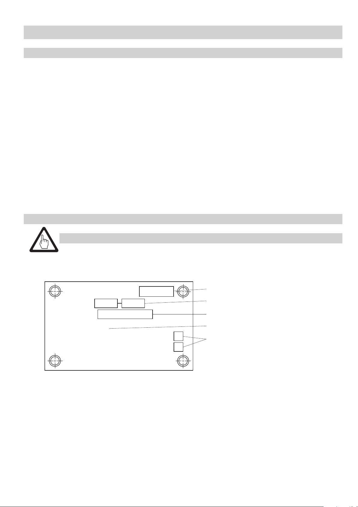
Attaching operating plates HV 215
Attach the operating plates at both sides of the tank car near the valves so that they are clearly visible.
1. Make sure that the surface onto which you want to stick the adhesive label is clean, dry and free of grease.
2. Remove the protective paper (“Controltac” printed on it) from the adhesive label.
3. Attach the operating plate at the desired position but do not yet stick it firmly to it.
As long as the operating plate is not firmly pressed against die surface you can still change its position.
4. To fix the operating plate permanently use a plastic spatula to press the adhesive label firmly against the surface.
Start in the middle of the label and make sure that no air gets trapped in.
5. Carefully strip off the protective sheet and, if necessary, press the corners of the operating plate again firmly
against the surface.
6. If there are air blisters prick a needle into them and then press the lable again firmly against the surface.
Attaching list indicating fluids
The fluid list must only be attached if bottom valves are used with a valve plug joint CR at both operating devices.
See drawing on page 4
Attach the fluid plates
Z at the middle of the inside of both flaps of the operating devices E so that they are
clearly visible.
29
Page 30

Installation – continued –
Filling and venting of hydraulic system
To fill the whole hydraulic system of the loading system carry out the following two steps:
1. Filling the hydraulic actuator system
Sequence: Both sides separately one after the other.
2. Filling the hydraulic indicating system
Sequence: 1. Liquid phase
2. Gas phase
The hydraulic system has to be filled after installing the loading system or when maintenance work or repairs have
been carried out.
Attention
Use only oils that are recommended by the manufacturer. Recommended oils are ESSO Zerice 22,
ARAL Vitamol 4004 or other oils with similar properties.
Filling and venting of hydraulic actuating system
Depressurise system before filling the hydraulic system.
See drawings on page 4 and page 23
1. Release the tension rope - the ball valve
36
of the control unit X of the bottom valve HWV 215/1 - DN 80
will automatically open the hydraulic system.
2. Unscrew the red plug
S and the dip stick of the oil filling connection of the hydraulic hand pump T
and fill oil into the tank.
3. Pull the tension rope in order to close the ball valve
36
of the control unit X of the bottom valve
HWV 215/1 - DN 80.
4. Operate the hydraulic hand pump
T until the resistance first increases perceptibly, the pressure limiting valve
responses audibly and then there is a distinct pressure relief. Then carry out 20 to 30 strokes with the pump
lever F of the hydraulic hand pump T in order to discharge the air in the hydraulic system via the pressure limiting valve.
5. Use the oil dip stick
S in the cover to check the oil level. If necessary refill oil and screw in plug S of oil filling
connection with a torque of 20 Nm.
6. Finally loosen the tension rope in order to re-open the hydraulic system.
Repeat the whole procedure with the second hydraulic hand pump
T.
30
Page 31

Installation – continued –
Filling and venting of hydraulic indicating system
Open both bottom valves before filling the hydraulic indicating system.
See drawing on page 4
1. Use the operating device
2. Loosen the venting plug
E to open the bottom valves.
Q of the actuating cylinder H of the liquid phase in the operating device E
by half a turn.
3. To fill the hydraulic indicating system connect an external oil hand pump with a pressure gauge
(measuring range: 0 - 20 bar) to the filling connection I of the bottom valve for the liquid phase.
Operate the pump until the oil leaves the venting plug Q of the indicating cylinder H without any bubbles.
4. Then fasten the venting plug
5. Continue to operate the external oil hand pump until the indicating piston
Q tightly.
O is completely moved out
and a pressure of approx. 10 to 20 bar is indicated by the pressure gauge.
6. Finally remove the external oil hand pump from the filling connection
I of the bottom valve and open
the hydraulic system by loosening the tension rope. The bottom valve closes automatically.
Follow the same steps when filling the bottom valve for the gas phase.
Performance test
Use both operating devices
E for the performance test.
See drawings on page 4 and page 23
1. To close the hydraulic system, pull the tension rope that closes the ball valve of the control unit
36
X
of the bottom valve HWV 215/1 - DN 80.
2. Use the pump lever
F of the hydraulic hand pump T in the operating device E and perform approx.
six strokes until you detect a slight resistance. The indicating pistons O of both bottom valves must now
be in the open position and they must be extended by approx. 46 mm.
3. During the hold time of approx. 2 hours the pressure must not decrease.
4. Check all connections and screwed unions for oil leaks. If necessary re-tighten the connections.
5. Then re-open the hydraulic system by loosening the tension rope.
6. Both bottom valves must close automatically and the indicating pistons
O in the operating devices E
must be at the lower position.
31
Page 32

Operation
Service
During the loading process the following actions will take place:
n Opening of bottom valve
n Closing of bottom valve
To open / close the bottom valves operate one of the operating devices
See drawing on page 4
When opening the operating device
1. To open the operating device
You can now swing down the lid.
2. Make sure that the pump lever of the hydraulic pump
3. Connect the rail hook
The ball valve of the control unit X of the bottom vale will close and the hydraulic system is ready for operation.
4. The up-strokes and down-strokes of the lever of the hydraulic hand pump
build up pressure in the hydraulic system, causing the two bottom valves to open simultaneously.
After approx. six strokes of the pump lever both bottom valves will be completely open. Check position
of bottom valves: The opening position of the bottom valves is indicated by the two completely extended
indicating pistons O of the indicating cylinders H (lift of indicating pistons approx. 46 mm).
5. Open the lateral shut-off valves
6. The pump lever of the hydraulic pump
Attention
If only one operating device for the loading system was opened, the lid of the other operating device
cannot be opened when the bottom valves are open.
C (e. g. rail hook VZ 10) to the tension rope and engage it in the rail.
E remove - if necessary - the custom‘s lead seal from the bolt M.
E push the bolt M upwards and then turn it by 90° to one side.
F is completely extended towards the front.
A to start the loading/unloading process.
F is no longer required and must be returned to its original position.
E at either side of the tank.
F in the operating device E
Close bottom valves immediately after loading or unloading the tank.
See drawing on page 4
7. To close the bottom valves disengage the the rail hook
The ball valve of the control unit X opens the hydraulic system and both rapid-action bottom valves will be
closed instantaneously. Be sure that both bottom valves are closed by checking the indicating pistons
of the indicating cylinders H. Both indicating pistons must be retracted.
8. Then close and latch the operating device
9. To finish the loading/unloading process close the shut-off valves
shut-off valves.
Attention
Note: If the lid cannot be closed, one or both bottom valves are still open!
The inside of the lid of the operating device features a bracket. This bracket prevents the closing
of the lid when one or both bottom valves are open. The lid can only be closed when the indicating
pistons are retracted. The cause of this malfunction must be ascertained and eliminated!
If only one operating device for the loading system was opened, the lid of the other operating device
cannot be opened when the bottom valves are open.
E.
C from the rail. This will loosen the tension rope.
O
A and attach the sealing plugs to the
32
Page 33

Operation – continued –
Emergency operation
During emergency unloading the following actions will take place:
n Opening of bottom valve
n Closing of bottom valve
If both bottom valves are to be opened, open first the bottom valve for the gas phase and then the one for
the liquid phase.
See drawing on page 4
1. Unscrew the sealing plug
A small amount of oil might escape. Put the sealing plug J in the operating device E.
2. Unscrew one or two of the required screws for sealing off the opening for emergency unloading
one of the two operating devices E and apply a smear of commercially available lubricant to them.
They are screwed one below the other at the back of the operating device E.
4. Screw the sealing-off screw
the bottom valve.
5. Open the lateral shut-off valves
Warning
Use the emergency operation of the bottom valves only if both hydraulic hand pumps have
failed or, for any other reason, there is not enough pressure for opening one or both bottom valves.
In case of emergency operation a rapid-action closing of the bottom valve is not possible.
If both bottom valves are to be closed via emergency operation, first close the bottom valve for the liquid
phase and then the one for the gas phase.
See drawing on page 4
J of the bottom valve located in the bottom of the actuating cylinder B.
K from
K into the thread at the bottom of the actuating cylinder B in order to open
A to start the loading / unloading process.
1. To close the bottom valve unscrew the sealing-off screw for emergency unloading
of the actuating cylinder B. The spring in the bottom valve effects the closing.
2. Once the emergency loading/unloading process has been accomplished, screw the sealing-off screws
back into the rear wall of the operating device E.
3. To finish the loading/unloading process, close the shut-off valves
the shut-off valves.
4. Defective bottom valves must be permanently marked in order to avoid inadvertent re-commissioning.
Do not screw sealing plugs J into defective bottom valves.
5. The cause of the malfunction must be ascertained and eliminated by qualified personnel!
Warning
In case of emergency operation a rapid-action closing of the bottom valve is not possible.
When the emergency operation of one or both bottom valves is finished, find and eliminate the
cause for the malfunction. Note that the repeated or continuous application of the emergency
operation is considered as improper usage. The resulting risk will have to be borne by the user alone.
The manufacturer hereby expressly rejects any claims for any resulting damage.
A and attach the sealing plugs to
K out of the bottom
K
33
Page 34

Maintenance
Bottom valves HWV 205/1 - DN 80/ HWV 215/1 - DN 80
Type of maintenance Time interval Activity
Check
valve plug seal
31
Replace
valve plug seal
31
Check
actuating cylinder B
Check
torque of 50 Nm
$
Check
torque of 120 Nm b
When necessary,
during main inspection
If a leak is detected replace valve plug seal
at the latest (every 4 yrs.)
Main inspection
(every 4 yrs.)
When necessary,
during main inspection
cylinder and body. If you detect an oil leak
at the latest (every 4 yrs.)
When necessary,
during main inspection
Check the torques of the four hexagon-head cap screws
of the actuating cylinder and, if necessary, retighten the
at the latest (every 4 yrs.)
When necessary,
34
during main inspection
at the latest (every 4 yrs.)
Check and, if necessary, re-tighten the six hexagon-head
cap screws of the body and the two hexagon nuts that fix
the control unit to the body with a torque of 120 Nm.
Check valve head for leaks.
as described in section “Maintenance”.
Replace valve plug seal as described
in section “Maintenance”.
Check connection between actuating
replace the PTFE seal and the O-ring
as described in section “Maintenance”.
screws to a torque of 50 Nm.
Check
smoothness of operation
of ball valve shaft
36
Replace
piston seal
(
When necessary,
during main inspection
at the latest (every 4 yrs.)
When necessary,
every 8 years at the latest
Check smooth operationg of switching shaft.
If the switching shaft does not move smoothly apply
a commercially available lubricant.
Replace piston seal
as described in section “Maintenance”.
34
Page 35

Maintenance – continued –
Operating device BV 110
Type of maintenance Time interval Activity
Check
oil level
Check
tightness
Check
valve lift
Check
holding pressure
Check
rapid-action closing
When necessary,
during main inspection
at the latest (every 4 yrs.)
When necessary,
during main inspection
at the latest (every 4 yrs.)
When necessary,
during main inspection
at the latest (every 4 yrs.)
When necessary,
during main inspection
at the latest (every 4 yrs.)
When necessary,
during main inspection
at the latest (every 4 yrs.)
The level in the tank of the hydraulic hand pump
must be above the lower marking on the dip stick.
Make sure that oil cannot escape at connections,
joints and T-type screwed unions.
If necessary, retighten respective connections.
With the hydraulic system closed, after approx. 6 lifts
of the hydraulic hand pump both indicating pistons
must be completely extended (height approx. 46 mm).
With the hydraulic system closed, both bottom valves
must withstand a constant pressure for two hours
without closing.
When disengaging the tension rope the rapid-action
closing must take place within one second and
the indicating pistons must be at the lower marking.
Check
completeness
Connecting lines
Type of maintenance Time interval Activity
Check
tightness
When necessary,
during main inspection
at the latest (every 4 yrs.)
When necessary,
during main inspection
at the latest (every 4 yrs.)
Both operating devices must have two emergency operating
screws each. These emergency operating screws must be
screwed in the rear wall.
Make sure that no oil can escape
at connecting joints and T-type screwed unions.
If necessary, retighten respective connections.
35
Page 36

Servicing
Hydraulic loading & unloading system HV 215
Observe the following servicing instructions whenever carrying out:
n Visual examinations as part of the main inspection
n Repair work due to leaks or other malfunctions
The bottom valves HWV 205/1 - DN 80 and HWV 215/1 - DN 80 require maintenance and servicing. The operating
device BV 110 is maintenance free.
We recommend removing the bottom valves HWV 205/1 - DN 80 and HWV 215/1 - DN 80 and checking them for
wear and damage when performing visual inspections.
Do not re-use parts subject to wear, such as gaskets and seals. Worn or damaged parts must be replaced after ascer
taining and eliminating the cause of the damage. Use only genuine GESTRA parts.
GESTRA supplies the following seal kits:
1. Stock code 049387
n 1 Valve plug seal PTFE
31
n 2 Gaskets ∅ 125 68
2. Stock code 049395
n 1 Valve plug seal CR
31
n 2 Gaskets ∅ 125 68
3. Stock code 049563
n 1 Piston seal §
n 1 Seal ring a
n 2 O-rings ()
n 1 Gasket !
n 1 Gasket &
Modifications to the design may only be made if the manufacturer‘s written permission is obtained.
-
Replacing valve plug seal
The valve head can be removed directly inside the tank. This option is highly recommended since in this case the
bottom valves, the connecting lines and the hydraulic system do not require any additional preparation.
If, however, the valve head can only be removed from the outside, please proceed as follows:
See drawings on page 4, page 6 and page 38
1. First disconnect all connections of the actuating cylinder
B. A small amount of oil might escape.
Collect the oil and dispose of it correctly.
2. If possible separate the manifold from the body.
3. To remove the body and the actuating cylinder
B unscrew the six hexagon-head cap screws b of the body
and remove the body and the associated actuating cylinder together. Remove gasket 8.
4. Undo the 12 socket-head cap screws
c and take the valve head from the mounting flange. For this purpose
you can screw two hexagon-head cap screws M 10 into the two through threads of the seat flange.
Note that these screws are not scope of the supply.
36
Page 37

Servicing – continued –
Replacing valve plug seal – continued –
Remove gasket 6.To remove the valve head proceed as follows:
See drawing on page 38
1. Secure the preloaded compression spring
f. For this purpose you can use a device (not scope of the supply)
that bears the load of the spring by means of leverage so that the 6 hexagon-head cap screws can be safely
loosened.
2. Then unscrew the six hexagon-head cap screws
1 with the locking washer 2 out of the stay bolt 4.
Take the valve plug e together with the spring plate 3 and the compression spring f out of
the seat flange. 7.
3. Then remove the retaining ring
4. Unscrew the four socket-head cap screws
h and the washer g.
i, take out the washer j and remove the valve plug seal .
31
Carefully clean all removed and dismantled parts.
Warning
Any use of naked flames is expressly forbidden!
Before performing any service work inside the tank make sure that the tank is sufficiently
ventilated and all gases have been completely vented. The rules concerning MAC (= maximum
allowable concentration) values at place of work must be strictly applied!
Note that an inadequately secured compression spring can lead to parts flying around, causing
serious injuries.
To mount the valve head proceed in reverse order of the removing procedure:
See drawing further down
1. Put the valve plug seal onto to valve plug
31
e and screw in the four socket-head cap screws i together
with the washer j, applying a torque of 15 Nm. Apply a commercially available lubricant to the screws
and tighten them in several steps in diagonally opposite pairs.
2. Then secure the washer
3. Screw the six hexagon-head cap screws
g by using the retaining ring h.
1 together with the locking washers 2 into the stay bolts 3,
using a torque of 25 Nm. Apply a commerically available lubricant to the screws and tighten them in several
steps in diagonally opposite pairs.
To mount the bottom valves from the outside follow the instructions given in section “Installation” (see page 17 for
HWV 205/1 - DN 80 and page 20 for HWV 215/1 - DN 80).
Attention
The specified torques must be strictly observed.
37
Page 38

Servicing – continued –
Replacing valve plug seal – continued –
1
2
3
4
5
6
7
31
ji h g
f
e
d
c
38
Page 39

Servicing – continued –
Reworking seat flange
If the seatings surface of the seat flange is slightly damaged you can remove and rework the seat flange.
For more details see drawing below.
To remove the seat flange please proceed as follows:
See drawing on page 38
1. Remove body and actuating cylinder.
2. Unscrew the 12 socket-head cap screws
the seat flange. Take out the gasket 6.
3. Unscrew the six stay bolts
Re-assembly in reverse order:
See drawing on page 42
1. First push the sleeves
to the seat flange 7. Apply a commerically available lubricant to the screws and tighten them.
2. To mount the valve head follow the indicated steps (see page 38).
3. Then put a new gasket
4. Use the 12 socket-head cap screws
to the mounting flange. Tighten them with a torque of 120 Nm. Apply a commercially available lubricant
to the screws and tighten them in several steps in diagonally opposite pairs.
4 together with their sleeves 5 out of the seat flange 7.
5 onto the six stay bolts 4 and then screw them with a torque of 25 Nm
6 onto the seat flange 7.
c and their associated locking washers d and remove
c together with their locking washers d to mount the valve head
Attention
The specified torques must be strictly observed.
∅ 85
Ra 0.8
max. 5 x 45°
39
Page 40

Servicing – continued –
Replacing gaskets of actuating cylinder
To remove the actuating cylinder proceed as follows:
See drawings on page 6 and page 41
1. If connecting lines are still attached to the actuating cylinder, you have to detach these connections
A small amount of oil might escape. Collect the oil and dispose of it correctly.
32
first.
2. Unscrew the four hexagon-head cap screws
$ in the bottom of the actuating cylinder and remove
the actuating cylinder.
3. First take out the sealing plug
% and the joint ring &. Use this opening to carefully pull the piston ",
the push rod 9 and the bellows 0 out of the actuating cylinder.
4. Take out the piston seal
5. Pull the piston
" out of the bellows 0.
6. Remove the retaining ring
§.
/ of the lower part of the bellows 0 and pull out the bushing =.
Take out the O-ring ) and the seal ring a.
7. Then remove the O-ring
To install the actuating cylinder
( from the actuating cylinder.
B proceed as follows:
See drawing on page 41
1. First insert a new O-ring
2. Insert first the seal ring
( in the actuating cylinder.
a and the O-ring ) in the lower part of the bellows 0. Then put the bushing =
into the bellows 0 and secure it with the retaining ring /.
3. Then place the piston seal
4. Put the piston
" into the bellows 0. Apply a light smear of hydraulic oil to the piston seal §.
§ onto the piston ".
Then put this component into the actuating cyclinder.
5. Screw the sealing plug
% with the joint ring & into the actuating cylinder.
40
Page 41

Servicing – continued –
Replacing gaskets of actuating cylinder – continued –
9
a
0
=
)
!
(
32
/
"
§
32
&%
41
Page 42

Servicing – continued –
Replacing control unit of bottom valve
In the control unit the ball valve with the tension rope will be replaced.
To remove the item proceed as follows:
See drawing further down
1. Disengage the spring from the lever of the ball valve .
2. Detach the hydraulic hoses .
3. Unscrew the two hexagon nuts and their locking washers and remove the ball valve .
42 36
41
39 40 36
To install the item proceed as follows:
1. Use two hexagon-head cap screws and hexagon nuts with washing lockers to fix the ball valve
to the support with a torque of 25 Nm.
37
2. Attach the connections for the hydraulic hoses .
3. Engage the spring in the lever of the ball valve .
42 36
38 39 40 36
41
Attention
The specified torques must be strictly observed.
42 41
36 37 38 39 40
42
Page 43

43
Page 44

Agencies all over the world:
www.gestra.de
España
GESTRA ESPAÑOLA S.A.
Luis Cabrera, 86-88
E-28002 Madrid
Tel. 00 34 91 / 5 15 20 32
Fax 00 34 91 / 4 13 67 47; 5 15 20 36
E-mail: aromero@flowserve.com
Great Britain
Flowserve Flow Control (UK) Ltd.
Burrel Road, Haywards Heath
West Sussex RH 16 1TL
Tel. 00 44 14 44 / 31 44 00
Fax 00 44 14 44 / 31 45 57
E-mail: gestraukinfo@flowserve.com
Italia
Polska
GESTRA POLONIA Spolka z.o.o.
Ul. Schuberta 104
PL - 80-172 Gdansk
Tel. 00 48 58 / 3 06 10 -02 od 10
Fax 00 48 58 / 3 06 33 00
E-mail: gestra@gestra.pl
Portugal
Flowserve Portuguesa, Lda.
Av. Dr. Antunes Guimarães, 1159
Porto 4100-082
Tel. 0 03 51 22 / 6 19 87 70
Fax 0 03 51 22 / 6 10 75 75
E-mail: jtavares@flowserve.com
USA
Flowserve S.p.A.
Flow Control Division
Via Prealpi, 30
l-20032 Cormano (MI)
Tel. 00 39 02 / 66 32 51
Fax 00 39 02 / 66 32 55 60
E-mail: infoitaly@flowserve.com
GESTRA AG
P. O. Box 10 54 60, D-28054 Bremen
Münchener Str. 77, D-28215 Bremen
Telephone +49 (0) 421 35 03 - 0
Fax +49 (0) 421 35 03 - 393
E-Mail gestra.ag@flowserve.com
Internet www.gestra.de
818480-01/1005cm · © 2003 GESTRA AG · Bremen · Printed in Germany
44
Flowserve DALCO Steam Products
2601 Grassland Drive
Louisville, KY 40299
Tel. 00 15 02 / 4 95 01 54, 4 95 17 88
Fax 00 15 02 / 4 95 16 08
E-mail: dgoodwin@flowserve.com
 Loading...