

Page 1

HV 205
Maintenance Instructions 818458-00
Hydraulic Loading & Unloading System HV 205
Page 2

For your notes
2
Page 3

Contents
Page
Important Notes
Usage for the intended purpose ...................... ................................................................8
Safety Notes ....................................................................................................................8
Danger.............................. ...............................................................................................9
Legal Regulations...................................................... ......................................................9
Explanatory Notes
Descripti on.....................................................................................................................10
Function............................ .............................................................................................11
Technical Data...............................................................................................................12
Checking
Hydraulic Loading & Unloading System HV 205 ...........................................................14
Bottom Valves HWV 205/1-DN 80 ................................................................................15
Connecting Lines...........................................................................................................15
Operating Devic e BV 100 ..............................................................................................16
Control Unit XV100........................................................................................................16
Maintenance
Hydraulic Loading & Unloading System HV 205 ...........................................................17
Replacing valve plug seal..............................................................................................18
Mounting bottom valve HWV 205/1-DN 80...................................................................20
Reworking seat flange .................................................................... ...............................23
Replacing gaskets of actuating cylinder ........................................................................24
Replacing control unit....................................................................................................26
Filling and venting of the hydraul ic system ................................................ ....................27
Filling and venting of hydraulic actuating system ..........................................................27
Filling and venting of hydraulic indicating system........................... ...............................28
Performance test ................................................................................................. ..........28
Operation
Operation .......................................................................................................................29
Emergency Operation....................................................................................................31
Annex
Revision............................................................................................................... ..........33
3
Page 4
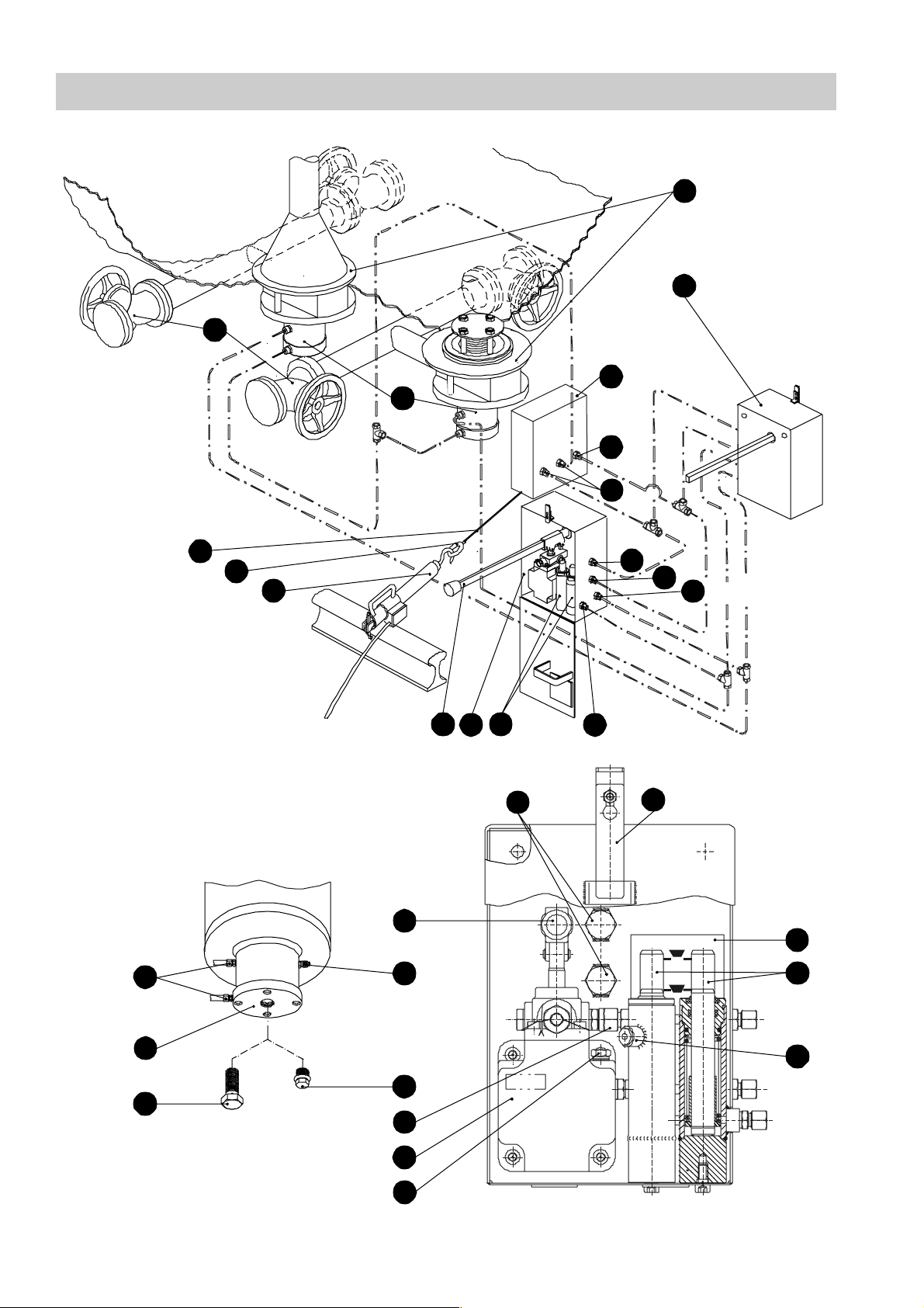
Components
E
A
B
C
D
R
P
X
F
H
I
B
K
J
Y
P
R
G
L
M
H
W
liquid phaseopengas phase
closed
N
O
D
Q
V
Y
U
T
S
4
Page 5

Key
A
Bottom valves HWV 205/1
B
Operating device BV 100
C
Control unit XV 100
D
Actuating cylinder
E
Shut-off valves
F
Tension rope with wire rope clamp
G
Line leading to the indicating cylinder of the gas phase
H
Ring
I
Rail hook
J
Pump lever of hydraulic hand pump
K
Indicating cylinder
L
Line leading to the indicating cylinder of the liquid ph ase
M
Bolt for operating device
N
Plate showing valve position of indicating pistons
O
Indicating pistons
P
Pressure line
Q
Screw-in plug for venting facility
R
Return line
S
Plug for oil filling connection (with dip stick)
T
Hydraulic hand pump
Non-return valve
U
Sealing plug
V
Filling connection
W
X
Connections
Screw for sealing off opening for emergency unloading
Y
5
Page 6
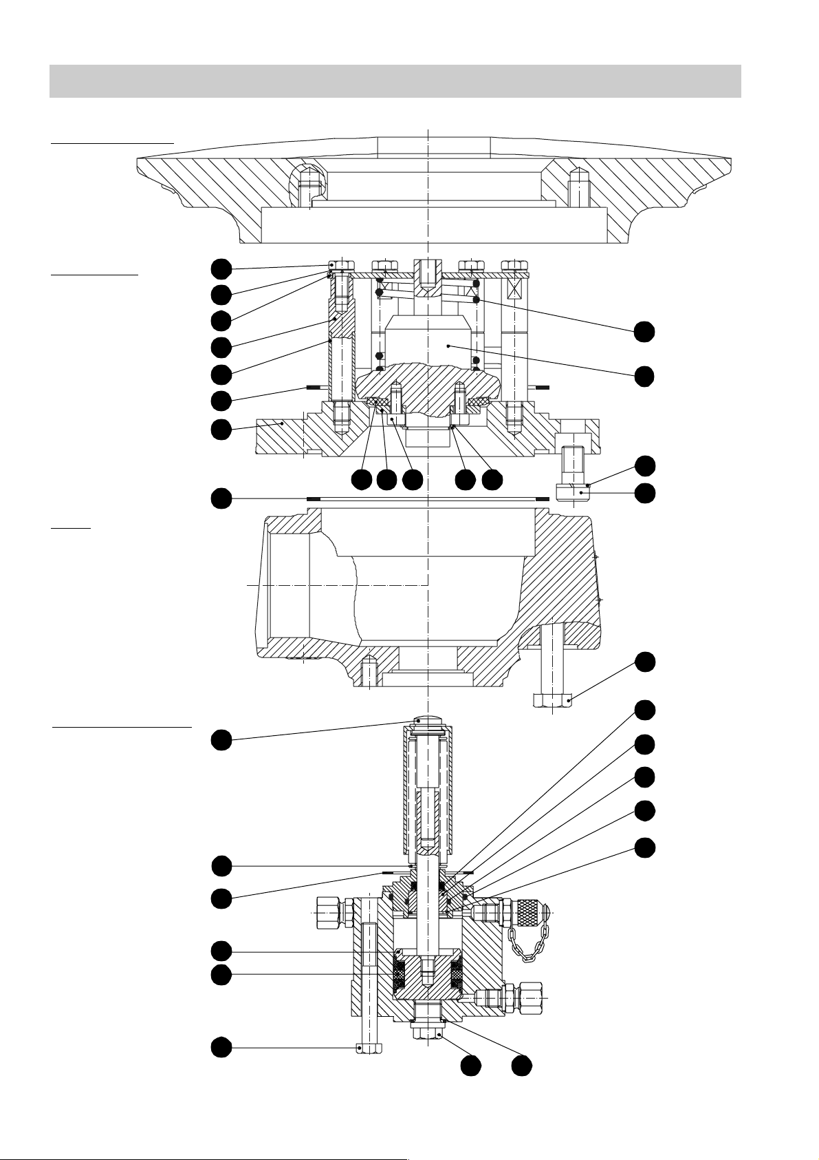
Basic Components of Bottom Valves
Mounti ng flange
Valve head
Body
1
2
3
4
5
6
7
29
3031
8
28
27
26
25
24
23
22
Actuating cylinder
10
11
12
13
14
21
9
15
16
20
19
18
17
6
Page 7

Key
1
Hexagon-head cap screw
2
Locking washer
3
Spring plate
4
Stay bolt
5
Sleeve
6
Gasket
7
Seat flange
8
Gasket
9
Push rod
10
Bellows
11
Gasket
12
Piston
13
Piston seal
14
Hexagon-head cap screw
15
Sealing plug
16
Joint ring
17
Retaining ring
18
O-ring
19
O-ring
20
Bushing
21
Seal ring
22
Hexagon-head cap screw
23
Socket-head cap screw
24
Locking washer
25
Valve plug
26
Compression spring
27
Washer
28
Retaining ring
29
Socket-head cap screw
30
Washer
31
Valve plug seal
7
Page 8

Important Notes
Usage for the intended purpose
The hydraulically operated loading and unloading system HV 205 is intended solely for
filling and draining stationary and mobile tanks containing pressure liquefied gases.
Its use is permissible only within the allowable pressure and temperature ratings and only
if the chemical and corrosive influences on the equipment are taken into account.
Changes in the design may only be performed if the manufacturer's written permission is
obtai ned.
Any type of use differing from the usage described above must be considered as
improper. The resulting risk will have to be borne by the user alone. The manufacturer
hereby expressly rejects any claims fo r any resulting damage.
Safety Notes
The loading and unloading system must not be installed, removed, commissioned,
operated or maintained by anyone other than qualified staff. Qualified staff are thos e
persons who - through adequate training, the use and applicatio n of safety equipment in
accordance with regulations concerning safety systems, and first aid & accident
preventi on - have achieved a recognised level of competence appropriate to the
installation and commissioning of this device.
For installation, removal, commissioning, operation and maintenance, every person who
works with the loading and unloading system must have read and understood the
complete installation manual. Furthermore, responsibilities must have been defined
clearly and unambiguously and must be adhered to.
Usage of the system for the intended purpose includes compliance with the rules and
notes in these installation instructions for installation, removal, commissioning, operation
and mai ntenance.
The operating company must ensure that, whenever the loading and unloading system
is being operated, it is in perfect condition.
Attention
Working methods that jeopardise safety must not be used!
8
Page 9

Important Notes – continued –
Danger
If the load ing and unloading system is used in an inexpert or improper manner by
unqualified statt, it can cause danger to life and limb for the use r or for third parties,
possibly resulting in d eath.
During oper ation, the bottom valves of the loaded and unloaded tanks are under
pressure. During the loading and unloading procedure all other components are also
under pressure. In this condition, screws as well as nuts and bolts of the loading and
unloading system must not be slackened. Liquid or vaporizing fluids might escape and
could cause severe cases of poi soning and environmental pollution.
During the loading and unloading procedure do not leave the installation unattended.
The shut-off valves might be cold during the loading and unloading procedure. Make sure
that the operator wears protective gloves when operating the handwheels.
Any installation or removal work may only be performed when the tank is at zero pressure
and completely free of gas.
When carrying out installation and maintenance work, make sure that the tank cannot be
operated accidentally.
Attention
Any use of naked flames is expressly forb idden!
Whene ver carrying out work inside the tank ensure su fficient ventilation
and gas venting. The rules concerning MAC (= maximum allowable
concentration) values at place of work mu st be strictly applied!
Legal Regulations
The configuration of the loading and unloading system HV 205 mounted to tank cars
carrying p ressurized gas meets the requirements of prEN 12561-3.
The two bottom valves HWV 205/1-DN80 fulfill the legal requirements of RID/GGVSE,
section 6.8, constituting the fi rst inner shut-off as defined in these regulations.
9
Page 10

Explanatory Notes
Description
The hydraulically operated loading and unloading system HV 205 is designed for filli ng
and draining stationary and mobile tank s containing pressure liquefied gases.
It is mainly used in tank cars carrying pressurized gases. These tank cars (TC) require a
high degree of reliability, ease of operation and maintenance and a long service life of the
associated valves.
The l oading and u nloadin g syste m c o nsist s of t he tw o r api d-a ction bott om va l ves, th e two
operating devices, the control unit, the shut-off valves, the rail hook and the tension rope.
The connecting lines required for operating the loading and unloading system are either
made of hydraulic tubes a nd hydraulic hoses or entirely of hydraulic hoses.
The bottom valves HWV 205/1-DN80 are fitted to the valve-mounting flanges at the
bottom of the vessel. Both bottom valves are always opened or closed together.
A manifold connects the bottom valves directly with the shut-off valves. Both valves can
eithe r be used for the liquid phase or the gas phase.
The operating devices consist of a hydraulic hand pump and one indicating piston for the
liquid phase and one for the gas phase. They are attached to the left and right hand side
of the tank car, which means that the bottom valves can be opened from either side of
the tank car by actuating t he respective operating device.
During the loading/unloading process the rail hook connected to the tensio n rope keeps
the bottom valves in the open positio n. In the event of an emergency, e. g. emergency
shut -off or inadvertent movi ng of the tank car, the rail hook is disengaged from the rail
and the bottom valves close instantaneously (rapid-action cl osing).
10
Page 11

Explanatory Notes – continued –
Function
The loading and unloading system HV 205 is designed for filling and draining tanks that
contain pr essure-liquefied gases.
One bottom valve opens for the liquid phase and the other opens for the gas phase. Both
opening p rocesses always take place simultaneously.
The operating device of the tension rope (e. g. rail hook VZ 10) engaged to one of the
rails provides the required tens ion of the rope. This tension keeps the ball valve of the
control unit of the hydraulic system closed.
The hydraulic hand pump of the operating device BV 100 can then be used to apply
pressure to the hydraulic system. The pressure acts on the actuating cylinders of the
bottom valves, forcing the piston to go up and thereby causing the bottom valves to open.
The current lift position of both bottom valves is indicated separately by the indicating
cylinders of the operating device BV 100.
When the rail hook is disengaged, i. e. when the load on the tension rope is reduced, the
hydraulic system opens, leading to the rapid-action closing of the bottom valves within
less than 1 second.
The integrated non-return valve prevents the premature closing of the bottom valves
caused by leaking fluids in the hydraulic hand pump and the pressure-reducing valve.
11
Page 12

Explanatory Notes – continued –
Technical Data
Attention
For pressure/temperature ratings of the bottom valves see name plate.
Name plate drawing Name plate specifications
GESTRA HWV
TÜ. AGG.
Manu.-no.:
P
: 37.5bar
test
T
: - 50°C valve plug seal PTFE
min.
T
: - 40°C valve plug seal CR
min.
Type of bottom valve
Type approval
GESTRA manufacturing no.
Test pressure
Type of valve plug seal
used in valve head
MADE BY GESTRA
Pressure/Temperature Ratings of Bottom Valves
Nominal pressure PN [bar] 25
Test pressu re [bar] 37.5
Temperature range for valve plug seal CR [ °C] – 40 to + 50
Temperature range for valve plug seal PTFE [°C] – 50 to + 50
Connection of bottom valve body
Sp ring press ure on valve plug [N] 250 ± 30
Lift of valve plug [mm] > 22.5
Drag coefficient ζ
Socket-weld ends for manifold
with O. D. 88.9 mm
Loading Unloading
3.3 2.8
12
Page 13

Explanatory Notes – continued –
Technical D ata - continued -
Item no. Component Material
—
22
14
25
26
10
6 8
31
Body 1.0566
Hex agon-he ad cap screw M 16 A2-70 or A4-70
Hex agon-he ad cap screw M 12 A2-70
7
3
4
11
Sea t flange 1.4571
Valve plug 1.4571
Compression s pring 1.4301
Spring plate 1.4301
Stay bolt 1.4301
Bellows, complete 1.4541 and 1.4571
Gasket PTFE
Valve plug seal PTFE or CR
23
18 19
5
Weight [kg]
Body 20 — —
Valve head 9 — —
Hy dr au li c ac tuat or 7 — —
Control unit — 7.9 —
Total 36 7.9 2x16
Socke t- hea d ca p screw A2- 7 0
O-ring NBR 70 Shore
Sleeve 1.4313
HWV 205/1 XV 100 BV 100
13
Page 14

Checking
Hydraulic Loading & Unloading System HV 205
We highly recommend that only qualified staff should carry out maintenance work in
accordance with these maintenance instructions. The manufacturer expressly rejects any
claims for damage caused by i m proper maintenance work.
All parts to be fitted must meet the technical requirements specified by the manufacturer.
All genuine parts are guaranteed to comply with these requirements.
For installation and removal work choos e lifting devices that ar e specified for the
respective weights. Use only suitable and proper li fting devices.
Make sure that the gaskets of the flanged connections are exactly placed between the
flang es. Clean all seating surfaces before installing the equipment.
The specified torques and tolerances must be strictly observed. Use appr opriate tools
and testing devices.
Before performing any service work inside the tank make sure that the tank is sufficiently
vent ilated and all gases have been completely vented. The rules concerning MAC
(= maximum allowable concentration) values at place of work must be strictly applied!
Remove the transport packing and all transit protection plugs for end connections before
installing the valves.
14
Page 15

Checking – continued –
Bottom Valves HWV 205/1-DN 80
Type of maintenance Time interval Activity
Check valve plug seal
Replace val ve plug seal
Check ac tuating cylinder
Check torque
of 50 Nm
Check torque
of 120 Nm
14
22
31
When necessary,
during main
ins pection at the late st
(every 4 yrs.)
31
D
Main inspection
(every 4 yrs.)
When necessary,
during main
ins pection at the late st
(every 4 yrs.)
When necessary,
during main
ins pection at the late st
(every 4 yrs.)
When necessary,
during main
ins pection at the late st
(every 4 yrs.)
Check valve head for leaks. If a leak is
detected replace valve plug sea l as
described in section "Maintenance".
Replace valve plug seal as descri bed in
section "Maintenance".
Ch ec k conn ec ti o n be twee n ac t u at ing
cylinder and body. If you detect an oil
leak repl ace the PTFE seal and the
O-ring as described in section
"Maintenance".
Chec k the torques of the f our hexagonhead c ap s crew s of the act ua t ing cy li nd er
and, if ne cessary , retighten the screws to
a torque of 50 Nm.
Check the torques of the six hexagon-
hea d c a p scr ews of the bo dy and , i f
necessary, ret ighten the screws to a
torque of 120 Nm.
Replace pis ton seal
13
When necessary,
every 8
year s at the lates t
Replace pis ton seal as described in
section "Maintenance".
Connecting Lines
Type of maintenance Time interval Activity
Make sure that no oil can escape
at connecting joints and T-type screwed
If necessary, retighten respective
connections.
Check tightness
When necessary,
during main
inspection at the
latest
(every 4 yrs.)
unions.
15
Page 16

Checking – continued –
Operating Device BV 100
Type of maintenance Time interval Activity
Whe n nece ssa r y,
Check oil level
durin g main
inspection at the
latest
(e very 4 yr s.)
The level in the tank of the hydraulic hand
pump must be above the lower marking on
the di p sti ck .
Check tightness
Check valve lift
Check holding pressure
Check rapid-acti on
closing
Whe n nece ssa r y,
durin g main
inspection at the
latest
(e very 4 yr s.)
Whe n nece ssa r y,
durin g main
inspection at the
latest
(e very 4 yr s.)
Whe n nece ssa r y,
durin g main
inspection at the
latest
(e very 4 yr s.)
Whe n nece ssa r y,
durin g main
inspection at the
latest
(e very 4 yr s.)
Make sure that oil cannot escape at
connec tions , joints and T-type screwed
unions. If necessary, retighten respective
connections.
With the hydraulic system closed, after
app r ox. 6 lift s of t h e hy dr au l ic ha nd pu m p
both indicating pistons mus t be completely
extended (height a pprox. 46 mm).
Wit h th e hydr au l ic sy s te m clo se d, bo th
bottom valves must withstand a constant
pressure for two hours without closing.
When dise ngaging the tension rope the
rapid-action closing must take place within
one second and the indicating pistons must
be at the lower marking.
Check completeness
Whe n nece ssa r y,
durin g main
inspection at the
latest
(e very 4 yr s.)
Both operating devices must have two
em er ge n c y op er a ti n g scr ews each . Th e se
emergency operating screws must be
scre wed in the rear wall.
Control Unit XV 100
Type of maintenance Time interval Activity
Check smoothness of
operation
of bal l val v e sh aft
35
Whe n nece ss ar y,
durin g main
in sp ec ti o n at th e
latest
(e very 4 yr s.)
Chec k smooth operation of switching shaft .
If the switching shaft does not move
smoothly apply a commercially available
lubrica nt.
16
Page 17

Maintenance
Hydraulic Loading & Unloading System HV 205
Observe the following maintenance instructions whenever carrying out:
Visual examinations as part of the main inspection
Repair work due to leaks or other malfunctions
The bottom valve HWV 205/1-DN 80 requires maintenance and servicing. The control
unit XV100 and the operating devices BV 100 are maintenance free.
We recommend removing the bottom valve HWV 205/1-DN 80 and checking it for wear
and damage when performing visual inspections.
Do not re-use parts subject to wear, such as gaskets and seals. Worn or damaged parts
must be replaced after ascertaining and eliminating the cause of the damage. Use only
genuine GESTRA parts.
GESTRA supplies the following seal kits:
1. Stock c ode 049387
1 Valve plug seal PTFE
2 Gaskets ø125
6 8
2. Stock c ode 049395
1 Valve plug seal CR
2 Gaskets ø125
6 8
3. Stock c ode 049564
1 Gasket
11
4. Stock c ode 049563
1 Piston seal
1 Seal ring
2 O-rings
1 Gasket
1 Gasket
13
21
18 19
11
16
31
31
Modifications to the design may only be made if the manufacturer's written permission is
obtained.
17
Page 18

Maintenance – continued –
Replacing valve plug seal
The valve head can be removed directly inside the tank. This option is highly
recommended since in this case the bottom valves, the connecting lines and the hydraulic
system do not require any additional preparation.
If, however, the valve head can only be removed from the outside, please proceed as
follows:
See drawings on pages 4, 6 and 19
1. First disconnect all connections of the actuating cylinder . A small amount of oil
X D
might escape. Collect the oil and dispose of it correctl y.
2. If possible separate the manifold from the body.
3. To remove the body and the actuating cylinder unscrew the 6 hexagon-head cap
screws of the body and remove the body and the associated actuati ng cylinder
together. R emove gasket .
4. Undo the 12 socket-head cap screws and take the valve head from the mounting
22
8
23
D
flange. For this purp ose you can s crew three hexagon-head cap screws M 12 into
the three through threads of the seat flange. Note that these screws are not scope of
the supply. Remove gasket .
6
To remove the valve head proceed as follows:
Drawing see page 19
1. Screw valve plug and spring plate together in order to secure the preloaded
compression spring . For this pur pose screw a hexagon-head cap screw M12
25 3
26
together with its associated washer (to ISO 7089-12) into the stem of the valve
25
plug . Note that neither the screw nor the washer are scope of the supply.
2. Then unscrew the six hexagon-head cap screws with the locking washers out
of the stay bolt . Take the valve plug together with the spring plate and the
compression spring out of the seat flange .
4 25 3
26
1 2
7
3. Then remove the retaining ring and the washer .
4. Unscrew the four socket-head cap screws , take out the washer and remove the
valve plug seal .
31
28 27
29
30
Carefully clean all removed and dismantled parts.
Warning
Any use of naked flames is expressly forb idden!
Before perfomring any service work inside the tank make sure that the
tank is sufficiently ventilated and all gases have been completely vented.
The rules concerning MAC (= maximum allowable concentration) values
at place of work must be strictly applied!
18
Page 19

Maintenance – continued –
Replacing valve plug seal - continued -
To mount the valve head proceed in reverse order of the removing procedure:
See drawing further down
1. Put valve plug seal onto v alve plug and screw in the four socket-head cap
screws together with the washer , using a torque of 15 Nm. Apply a commerically
29 30
31 25
available lubricant to the screw s and tighten them in several steps in diagonally
opposite pairs.
2. Then secure the wa sher by using the retaining ring .
3. Screw the 6 hexagon-head cap screws tog e ther with the locking washers into
the sta y bolts , applying a torque of 25 Nm. Apply a commerically available
3
27 28
1 2
lubricant to the screws and tighten them in several steps in diagonally opposite pairs.
4. Unscrew the centrally aligned hexagon-head cap screw with the washer from the
valve plug .
25
Attention
The specified torques must be strictly observed.
1
2
3
26
4
5
25
6
7
31
30
29
28
27
24
23
19
Page 20

Maintenance – continued –
Mounting bottom valve HWV 205/ 1 - DN 80
Before mounting the bottom v alve first attach the val ve head from the outside to the
mounting flange.
Drawing see page 22
1. Put the gasket onto the valve head.
2. Place valve head onto the mounti ng flange and tighten socket-head cap screws
and locking washer with a torque of 120Nm. Apply a commerically available
6
23
24
lubricant to the screws and tighten them in several steps in diagonally opposite pairs.
3. Check spacing between bottom of valve plug and seat flange (reference
25 7
dimension 1 see page 22). For this purpose you can hold a try square to the bottom
of the valve head and read off the distance to the bottom of the valve plug. A distance
of 7±1mm is required. If the reading exceeds this tolerance check the position of the
valve plug seal of the valve plug . If necessary pus h the valve plug slightly
31 25 25
upwards.
Dirty seals or the incorrect position of the valve plug seal ma y have caused the
31
problem. Should even after this examination the actual readings sti ll exceed the
specified tolerances, please co ntact our Technical Service in your country, stating
the Gestr a manufacturing numb er indicated on the name plate.
Attention
Check and, if necessary, clean sealing sur faces.
The specified torques must be strictly observed.
20
Page 21

Maintenance – continued –
Mounting bottom valve HWV 205 /1 - DN 80 - continued -
After the valve head install the body with the actuating cylinder.
See drawings on pages 4 and 22
1. Re-attach manifold to the body if it was previously detached from the body so that
the bottom valve could be removed.
To connect the manifold it might be necessary to remove the actuating cylinder
from the body. For this purpose unscrew the hexagon-head cap screws and
carefully push the actuating cylinder with your hands downwards.
Remove gasket . Do not re-use this gasket! Insert a new gasket .
A
D
14
D
11 11
2. Check the torque (50 Nm) required for tightening the hexagon-head cap screws .
If the actuating cyl inder has been removed, tighten the hexagon-head cap
screws with a torque of 50Nm. Apply a commerically available lubricant to the
14
D
14
screws and tighten them in several steps in diagonally oppos ite pairs.
3. Then check the lift of the push rod in the body with actuating c ylinder . For this
9 D
purpose measure the reference dimension 2 and 3 (see page 22) from the upper
edge of the push rod to the sealing surface of the unloaded bellows and to the
lower stop of the bellows . If the distance exceeds the admissible tolerance, check
the push rod for smooth operation. If the push rod is jammed, first eliminate the
9
cause and then gently knock with your hand against the push rod until it can move
9 10
10
9
freely. If you cannot find a fault please contact our Technical Services in your country,
stating the GESTRA manufacturing number.
4. Insert a new gasket in the bottom of the valve head and use the hexagon-head cap
screws to screw the body to the mounting flange, applying a torque of 120Nm.
22
8
Apply a commerically available lubricant to the screws and tighten them in several
steps in diagonally opposite pairs.
5. Re-install the connecting lines to the connections of the actuating cylinders . Use
a spanner A. F19. Apply a torque of 40 Nm to fasten the connections .
X D
X
Attention
If welding or annealing is necessary make sure that gaskets and seals are
not damaged in the pr ocess. Check and, i f necessary, clean sealing
surfaces.
Always replace gasket when removing the actuating cylinder.
The specified torques must be strictly observed.
Note: Do not use the push rod as handle!
Check the soft seals of the connections for damage. Only soft seals that
are not damaged c an be used again. Replace damaged gaskets and
seals.
21
Page 22

Maintenance – continued –
°
Mounting bottom valve HWV 205 / 1 - DN 80 - continued -
Ø 210 / 12x M16
Ø 146
M12
25
8
7
6
Manifold
Ø88.9
14
5
,
6
1
1
8
2
9
2
turned
through 90°
Torque 50Nm
turned through 45°
31
11
10
Ø 112
9
24
7
Torque 120Nm
23
turned through15
Torque 120Nm
22
turned
32
through 90°
Reference dimension 1
on valve head
±1
7
22
Reference dimension 2
on body with
actuating cylinder
(bellows unloaded)
+9
16
Reference dimension 3
on body with
actuating cylinder
(bellows at lower stop)
±1
1
Page 23

Maintenance – continued –
Reworking seat flange
If the seating surface of the seat flange is slightly damaged you can remove and rework
the seat f lange. For more details see drawing below.
To remove the seat flange please procee d as follows:
Drawing see page 19
1. Remove body and the actuating cylinder .
2. Unscrew the 12 socket-head cap screws and their associated locking wash ers
and remove the seat flange. Ta ke out the gasket .
3. Unscre w the 6 stay bolts together with the sleeves out of the seat flange .
4 5 7
D
23 24
6
Re-assembly in reverse order:
Drawing see page 19
1. First push the sleeves onto the 6 stay bolts and screw them with a torque of 25
Nm to the seat flange . Apply a commerically available lubricant to the screws and
5 4
7
tighten them.
2. To mount the valve head follow the spec ified proced ure (see page 19).
3. Then put a new gas ket onto the seat flange .
4. Use the 12 socket-head cap screws together with their locking washers to
6 7
23
24
attach the valve head to the mounting flange. Tighten them with a torque of 120 Nm.
Apply a commerically available lubricant to the screws and tighten them in several
steps in diagonally opposite pairs.
Attention
The specified torques must be strictly observed.
Ra 0.8
max.5x45°
(Ø85)
23
Page 24

Maintenance – continued –
Replacing gaskets of actuating cylinder
To remove the actuating cylinder pro ceed as follows:
Drawings see pages 6 and 25
1. If connecting lines ar e still attached to the actuating cylinder you have to detach
these lines first. A small amount of oil might escape. Collect the oil and dispose of
32
D
it correctly.
2. Unscrew the four hexagon-head cap screws i n the bottom of the actuating
cylinder and remove the actuating cylinder .
3. First take out the sealing plug and the joint ring . Use this opening to carefully
pull the piston , the push rod and the bellows out ot the actuating cylinder .
4. Take out the piston seal .
5. Pull the piston out of the bellows .
6. Remove the retaining ring of the lower part of the bellows and pull out the
bushing . Take out the O-ring and the seal ring .
7. Then remove the O-ring from the actuating cylinder .
To install the actuating cylinder proceed as follows:
D D
15 16
12 9 10 D
13
12 10
17 10
20 19 21
18 D
D
14
Drawing see page 25
21
18 D
19
10
1. First insert a new O-ring in the actuating cylinder .
2. Insert the seal ring and the O-ring in the lower part of the bellows . Put the
bushing into the bellows and secure it with the retaining ring .
20 10 17
3. Then place the piston seal onto the piston .
4. Put the piston into the bellows . Apply a light smear of hydraulic oil to the piston
13 D
seal . Then put this component into the actuating cyclinder .
12 10
5. Screw the sealing plug with the joint ring into the actuating cylinder .
13 12
15 16 D
24
Page 25

Maintenance – continued –
Replacing gaskets of actuating cylinder - continued -
9
21
10
20
19
11
18
32
17
12
13
32
15 16
25
Page 26

Maintenance – continued –
Replacing control unit
In the control unit the ball valve with the tension rope will be replaced.
To remove the item proceed as follows:
See drawing further down
1. First undo the four socket-head cap screws of the case of the control unit and
remove them together with the four hexagon nuts . You can now take off the cover.
2. Disengage the spring from the lever of the ball valve .
37 36 35
3. Detach the connections of the hydraulic tubes and remove the ball valve .
4. The pressure-limiting valve and the non-r eturn valve can be replaced once the
40 41
respective connections of the hydraulic tubes have been detached.
38 34 C
39
33 35
33
To install the item proceed as follows:
1. Once the pressure-limiting valve and the non-return valve have been replaced,
re-attach the valves to the connections of the hydraulic tubes .
2. Screw the ball valve between the connections of the hydraulic tubes .
3. Engage the spring in the lever of the ball valve .
35 33
37 36 35
4. Use the four socket-head cap screws and the four hex agon nuts to screw the
cover to the case of the control unit .
34 C
40 41
38 39
33
40
33
33
26
34
33
35 39
3736
38
41
33
Page 27

Maintenance – continued –
Filling and venting of the hydraulic system
To fill the whole hydraulic system of the loading system carry out the following two steps:
1. Filling the hydraulic actuator system
Sequence: Both sides separately one after the other.
2. Filling the hydraulic indicating system
Sequence: 1. Liquid phase
2. Gas phase
The hydraulic system has to be filled after installing the loading system or when
maintena nce work or repairs have been carried out.
Attention
Use only oils that are recommended by the manufacturer. Recommended
oils are ESSO Zerice 22, ARAL Vitamol 4004 or other oils with similar
properties.
Filling and venting of hydraulic actuating system
Depressurise system before filling the hydraulic system.
Drawings see pages 4 and 26
1. Loosen the tension rope . The ball valve of the control unit opens the hydraulic
F 35 C
system automatically.
2. Unscrew the red plug and the dip stick of the oil filling connec tion of the hydraulic
hand pump and fill the oil in the reservoir.
T
3. Pull the tension rope so that the ball valve of the control unit will close.
4. Operate the hydraulic hand pump until the resistance first increases perceptibly,
S
F 35
T
C
the pressure limiting valve responses audibly and then there is a distinct pressure
relief. Then carry out 20 to 30 strokes with the pump lever of the hydraulic hand
pump in order to discharge the air in the hydraulic system via the pressure-limiting
T
J
valve.
5. Use the oil dip stick in the cover to check the oil level. If necessary refill oil and
screw in plug of oil filling connection with a torque of 20Nm.
S
6. Finally loosen the tension rope in order to re-open the hydraulic system.
S
F
Repeat the whole procedure with the second hydraulic hand pump .
T
27
Page 28

Maintenance – continued –
Filling and venting of hydraulic indicating system
Open both bottom valves before filling the hyd raulic indicating system.
Drawing see page 4
1. Use the operating device to open the bottom valves .
2. Loosen t he venting plug of the actuating cylinder of the liquid phase in the
operating dev ice by half a turn.
B
B
Q K
A
3. To fill the hydraulic indicating system connect an external oil hand pump with a
pressure gauge (measuring range: 0-20 bar) to the filling connection of the bottom
valve for the liquid phase. Operate the pump until the oil leaves the venting plug
of the indicating cylinder without any bubbles.
4. Then fasten the venting plug tightly.
A Q
K
Q
5. Continue to operate the external oil hand pump until the indicating piston is
W
O
completely moved o ut and a pressure of approx. 10 to 20bar is indicated by the
pressure gauge.
6. Finally remove the external oil hand pump from the filling connection of the bottom
valve and open the hydraulic system by loosening the tension rope . The bottom
valve closes automatically.
A F
A
W
Follo w the same s teps when filling the bottom valve for the gas phase.
Performance test
Use both operating devices for the performance test.
B
Drawings see pages 4 and 26
1. To close the hydraulic system pull the tension rope that closes the ball valve of
the control unit .
2. Use the pump lever of the hydraulic hand pump in the operating de vice and
C
J
F 35
T
B
perform approx. six strokes until you detect a slight resistance. The indicating
pistons of both bottom valves must now be in the open position and they must
O A
be extended by approx. 46mm.
3. During the hold time of approx. 2 hours the pressure must not decrease.
4. Check all connections and screwed unions for oil leaks. If necessary re-tighten the
connections.
5. Then re-open the hydraulic system by loosening the tension rope .
6. Both bottom valves must close automatically and the i ndicating pistons in the
operating dev ices must be at the lower position.
A O
B
F
28
Page 29

Operation
Operation
During the loading process the following acti ons will take place:
Opening of bottom valve
Closing of bottom valve
To open/ close the bottom valves operate one of the operating devices at either side
A B
of the tank.
Drawing see page 4
If necessary remove custom's lead seal from the bolt when opening the operating
device .
1. To open the operating device push the bol t upwards and then turn it by 90° to
B
B M
M
one side. You can now swing down the lid.
2. Make sure that the pump lever of the hydraulic pump is completely extended to
J
T
the front.
3. Connect the rail hook (e. g. rail hook type VZ 10) to the tension rope and
engage it in the rail. Pull the tension rope tightly such that the ball valve of the
control unit is closed and the hydraulic system i s ready for operation.
C
4. The up-strokes and down-strokes of the l ever of the hydraulic hand pump in the
operating device built up pressure in the hydraulic system, resulting in the
simultaneous opening of both bottom valves . After approx. six s trokes of the pump
lever both bottom valves will be completely open. Check position of bottom
J A
valves: The opening position of the bottom valves is indicated by the two indicating
pistons of the indicating cylinders which must be completely moved out (lift of
O K
I
F
J
B
A
A
F
T
indicating pistons approx. 46mm).
5. Open the lateral shut-off valves to start the loading/unloading process.
6. The pump lever of the hydraulic pump is no longer required and must be
J
E
T
returned to its original position.
Attention
If only one operating device for the loading system was opened, the lid of
the other operating device cannot be opened when the bottom valves are
open.
29
Page 30

Operation – continued –
Operation - continued -
Close bottom valves immediately after loading or unloading the tank.
Drawing see page 4
1. To close the bottom valves disengage the rail hook from the rail. This results in
the tension rope being loosened. The ball valve of the control unit opens the
F C
hydraulic system and both rapid-action bottom valves will be closed
instantaneously. Be sure that both bottom valves are closed by checking the
indicating pistons of the indicating cylinder . Both indicating pistons must be
O K
A I
A
A
retracted.
2. Then close and latch the operati ng device .
3. To finish the loading/unloading process close the sh ut-off valves and attach
sealing plugs to shut- o ff valves .
E
B
E
Attention
Note: If the lid cannot be closed, one or bo th b ottom valves are still open!
The inside of the lid of the operating device features a bracket. This
bracket prevents the closing of the lid when one or both bottom valves are
open. The lid can only be closed when the indicating pistons are retracted.
The cause of this malfunction must be ascertained and eliminated!
If only one operating device for the loading system was opened, the lid of
the other operating device cannot be opened when the bottom valves are
open.
30
Page 31

Operation – continued –
Emergency Operation
During emergency unloading the following actions will take place:
Opening of bottom valve
Closing of bottom valve
If both bottom valves are to be opened, open first the bottom valve for the gas phase
A
and then the one for the liquid phase.
Drawing see page 4
1. Unscrew the sealing plug of the bottom valve located in the bottom of the
actuating cylinder . A s m all amount of oil might escape.
Put the sealing plug in the operating device .
D
V B
V
A
2. Unscrew one or two of the required screws for sealing off the opening for emergency
unloading from one of the operating devices and apply a smear of commercially
Y B
available lubricant to them.
They are screwe d one below the othe r to the back of the operating device .
4. Screw the sealing-off screw into the thread at the bottom of the actuating
cylinder in order to open the bottom valve .
D A
5. Open the lateral shut-off valves to start the loading/unloading process.
Y
E
B
Warning
Use the emergency operation of the bottom valves only if both hydraulic
hand pumps have failed or, for any other reason, there is not enough
pressure for openin g one or both bottom val ves.
In case of emergency operation the rapid-action clos ing of the bottom
valve is not possible.
31
Page 32

Operation – continued –
Emergency Operation - continued -
If both bottom valves are to be closed via emergency operation, first close the bottom
valve for the liquid phase and then the one for the gas phase.
Drawing see page 4
1. To close the bottom valve unscrew the sealing-off screw for emergency
unloading out of the bottom of the actuating cylinder . The spring in the bottom
valve effects the closing.
Y D
A
A
2. Once the emergency loading/unloading process has been accomplished, screw the
sealing-off screws back into the rear wall of the operating device .
3. To finish the loading/unloading process close the sh ut-off valves and attach the
sealing plugs to the shut-off valves .
4. Defective bottom valves must be permanently marked in order to avoid
Y B
E
E
A
inadvertent re-commissioning.
Do not screw sealing plugs into defective bottom valves .
V A
5. The cause of the malfunction must be ascertained and eliminated by qualified
personnel!
Warning
In case of emergency operation a rapid-action closing of the bottom valve
is not possible.
When the emergency operation of one or both bottom valves is finished,
find and eliminate the cause for the malfunction. Note that the repeated or
continuous application of the emergency operation is considered as
improper usage. The resulting risk will have to be borne by the user alone.
The manufacturer hereby expressly rejects any claims for any resulting
damage.
32
Page 33

Annex
Revision
Index
00 Maintenance instr uctions - new - 22 Sep t. 2003
Designation Date
33
Page 34

GESTRA Gesellschaften • GESTRA Companies • Sociétés GESTRA • Sociedades Gestra • Società GESTRA
Ve rtretungen w eltweit • Agencies all over the wo rld • Re pr ésentation s dans le monde entier • Repr esentac ione s en todo e l mundo • Agenzie in tutto il mondo
Großbritannien
Flowserve Flow Control (UK) Ltd.
Burrel Road, Hay wards Heath
West Sussex RH16 1TL
Tel. 00 44 14 44 / 31 44 00
Fax 00 44 14 44 / 31 45 57
E-mail: sales@flowserve.com
France
Flowserve Flow Control S.A.S.
10 Avenue du Centaure, BP 8263
F-95801 CERGY PONTOISE CEDEX
Tél. 0 03 31 / 34 43 26 60
Fax 0 03 31 / 34 43 26 87
E-mail: gnation@flowserve.com
España
GESTRA ESPAÑOLA S.A.
Luis Cabrera, 86-88
E-28002 Madrid
Tel. 00 34 91 / 5 152 032
Fax 00 34 91 / 4 136 747; 5 152 036
E-mail: gestra@gestra.es
Italia
Flowserve S.p.A.
Divisione Italgestra
Via Prealpi, 30, I-20032 Cormano (MI)
Tel. 00 39 02 / 66 32 51
Fax 00 39 02 / 66 32 55 60
E-mail: info@italgestra.it
Portugal
Flowserve Portuguesa, Lda.
Av. Dr. Antunes Guimarães, 1159
Porto 4100-082
Tel. 0 03 51 22 / 6 19 87 70
Fax 0 03 51 22 / 6 10 75 75
E-mail: jtav ares@flowserve.com
GESTRA GmbH
®
P os tfach 10 54 6 0, D-28054 Bremen, Mü nc hen er S tr. 77 , D-28215 B r em en
Telefon +49 ( 0) 421 35 03-0, Telefax +4 9 ( 0) 42 1 35 03-393
E-Mail ges tra. gmb h@ fl ows erve .c o m, In te r net ww w. ges tra .de
An Unit of Flowserve Corporation
818458-00/404agt ©2003 GESTRA GmbH Bremen Printed in Germany
 Loading...