

Page 1
Flow Solutions Division
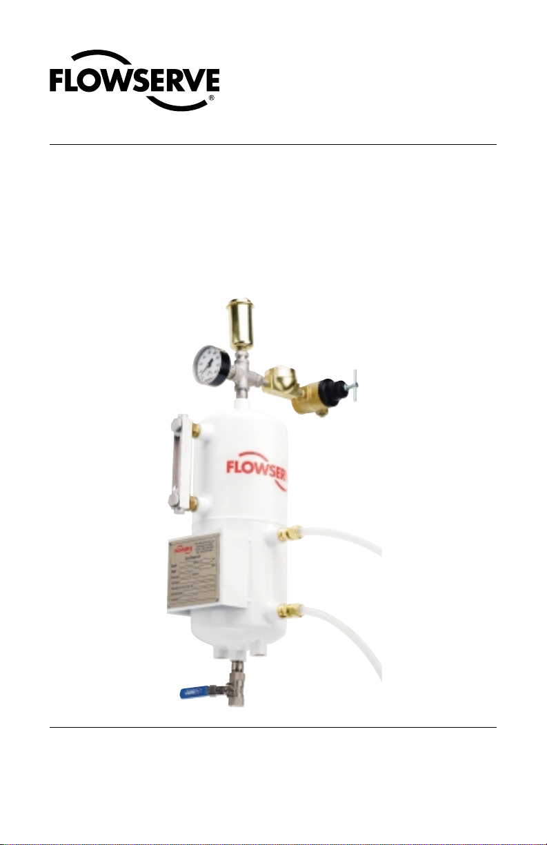
CPM Seal Support
Reservoir Assembly
Installation Instructions
Page 2

Introduction
This manual covers the installation and operation of the CPM Seal
Support Reservoir for dual non-pressurized (API Plan 52/ANSI Plan
7352) and dual pressurized seals (API Plan 53/ANSI Plan 7353). The
following instructions describe the appropriate system, buffer/barrier
fluids, installation, start-up, and maintenance.
Reservoir
The standard CPM Seal Support Reservoir is designed in accordance
with ASME Code Section VIII, Division 1. All tanks are welded in accordance with ASME Code Section IX. Tanks include inlet, outlet, vent and
fill along with two mounting lugs as minimum connections.
Sealing System Description
CPM Seal Support Reservoir can be used as reservoirs for dual pressurized Inside, dual pressurized inside/outside or dual non-pressurized
Flowserve Seal designs. The sealing system produced is defined as
being either a thermal convection system or a forced circulation system.
Support System Descriptions
An API Plan 53/ANSI 7353 is a pressurized dual seal system which is
used in services where no process leakage to atmosphere is tolerated.
The system consists of dual mechanical seals with a barrier fluid between them. The barrier fluid in the supply tank is pressurized to a higher
pressure (normally 25 psig [1.7 bar]) than the seal chamber maximum
160 psig [11 bar]). Primary (inboard) seal leakage will be barrier fluid into
the product. Minimal leakage is customary.
An API Plan 53/ANSI Plan 7353 is usually chosen over an API Plan 52/
ASNI Plan 7352 for dirty, abrasive, or polymerizing products which would
either damage the seal faces or cause problems with the barrier fluid
system if an API Plan 52/ANSI Plan 7352 is used. Two conditions to
consider when incorporating API Plan 52/ANSI Plan 7352; first, there will
always be some leakage of barrier fluid into the product. Normally, this
leakage will be minute, and the leakage rate can be monitored via the
2
© Copyright 2004 Flowserve Corporation
Page 3
visual water flow indicator. However, when using API Plan 53/ANSI Plan
7353 the product must be able to accommodate a small amount of
contamination from the barrier fluid. Secondly, an API Plan 53/ANSI Plan
7353 system is dependent on having the supply tank pressure maintained at the proper level. If the supply tank pressure drops below seal
chamber pressure, seal leakage direction will be reversed and the barrier
fluid will be contaminated with the process fluid. The flush plan will then
become an API Plan 52/ANSI Plan 7352.
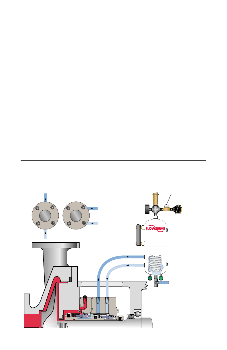
An Induced Circulation System is essentially the same as the thermal
convection system except for the addition of a circulating device in the
seal cavity which provides for positive flow in the system. The addition of
a circulating device provides for positive flow of buffer fluid shown in
Figure 1. To maximize dual seal cooling add cooling coils inside the
reservoir as a means of removing heat.
Dual Pressuzied Inside Seal with Induced Circulation
through CPM Seal Support Reservoir with Cooling Coil
Figure 1
Plan 53/ANSI Plan 7353
vertical
porting
outlet
end view
inlet
seal
tangential
or
porting
seal
end view
outlet
inlet
vent valve
pressure
gage
level
gage
cooling out
visual water
flow indicator
water
pressure
regulator
and inlet
port
304SS,
2 gallon
reservoir
cooling in
drain
3
Page 4

Buffer/Barrier Fluid Selection
The CPM Seal Support Reservoir is designed for use with water barrier
only in conjunction with a water header system.
For an API Plan 53/ANSI Plan 7353 pressurized barrier fluid system
where the method of pressurization is a gas blanket, special attention is
given to the application conditions. Gas solubility in the barrier fluid
increases with the rising temperature and pressure. However, the CPM
Seal Support Reservoir is designed for pressurization from a water
header system. The water header system provides pressure to the seal
when pressurized above operating conditions in a dual pressurized
operating mode. Should consumption of barrier water increase the
header system will automatically refill the tank. The water regulator on
the inlet of the tank determines the point of re-supply. The pressure level
at which re-supply is accomplished is adjustable to suit the application
need.
The condition of the water within the tank should be checked over the
entire operating curve of the application. Particular attention should be
paid during start up conditions. Water on the seal at the time of start up
is a critical condition for longevity of seal life. Also close care should be
taken to ensure water conditions are maintained to avoid pressure
reversals contaminating barrier water with process fluids.
1. The water should not freeze at the minimum site ambient temperature.
2. The water should have an initial boiling point at least 50°F above the
temperature to which it will be exposed.
3. The water should not have a flash point higher than the service
temperature.
4
Page 5

Installation
1. The reservoir is mounted vertical not more than 3 feet (.9 m) from
the seal gland to the vertical centerline of the reservoir. The bottom
of the reservoir is mounted 12 to 24 inches (.3m to .6 m) above the
horizontal centerline of the pump.
2. All lines from the seal cavity to the reservoir must slope upward at
all points. The upward slope should be a minimum of 1/4" per foot
(24 cm/m) with all bends being large radius. The minimum size for
pipe or tubing should be 1/2" (13 mm) diameter.
3. Connect the supply connection (lower seal connection on the
reservoir) to the bottom (inlet) gland connection.
4. Connect the return connection (upper seal connection on the
reservoir) to the upper (outlet) gland connection.
5. If valves are used to isolate the seal chamber and the reservoir
make sure these are fully open while filling and during operation.
6. If the reservoir is equipped with cooling coils, connect cooling water
lines to the reservoir at the cooling coil points.
7. Remove all plastic plugs and properly seal or attach tubing with
metal fittings.
5
Page 6

8. It is highly recommended that the reservoir be flushed with clean
fluid prior to equipment start up to remove any foreign matter from
the system.
Caution:
The CPM Seal Support Reservoir System is not for use with
hazardous materials.
9. Fill reservoir with water barrier fluid to the middle of the sight
glass. Gas volume of the system should be at least 25 percent of
the reservoir volume to allow for thermal expansion during operation.
10. Before starting the system, bleed all air from highest point in the
system, the vent valve.
11. Connect external water supply to reservoir on Plan 53 (dual seal). A
pressure regulator and check valve are required to maintain a
constant pressure on the system. The pressure in the reservoir
should be maintained at least 25 psi above the seal cavity pressure.
Make sure reservoir is filled before pressurizing.
6
Page 7

Start-Up
1. API Plan 52/ANSI Plan 7352 - open valve to the vent or process
recovery system slowly.
2. API Plan 53/ ANSI 7353 - slowly open valve between reservoir and
external pressurization source. Slowly increase the pressure to avoid
gas ingestion. Check for leaks as unit is being pressurized. Operating
pressure is normally 25 psi above seal cavity pressure. The pressure
gauge on system can be used to monitor system pressure.
3. If system is equipped with cooling coils open valve to allow water to
flow through coils.
4. The main pump can now be started.
Maintenance
During planned plant shutdowns it is recommended that the buffer/barrier
fluid be drained, reservoir flushed and new fluid put in the reservoir. This
will ensure the quality of the buffer/barrier fluid used to lubricate the seals
and to remove any particles that may have accumulated in the reservoir.
When changing or cleaning the glass on armored sight gages (weld pad
level gage) always install new gaskets and retorque bolts to proper
amount. It is also recommended that the bolts be checked and retorqued
prior to first operation. They can come loose during shipping and transport.
7
Page 8

TO REORDER REFER TO
B/M #
F.O
.
All Flowserve Corporation, Flow Solutions Division, products must be installed in accordance with Flowserve
installation instructions. Failing to do so or attempting to change or modify Flowserve products will void
Flowserve’s limited warranty. Flowserve’s limited warranty is described fully in Flowserve’s Standard Terms
and Conditions of Sale. Flowserve makes no warranty of merchantability or fitness for a particular purpose
and in no event shall Flowserve be liable for consequential or incidental damages.
Flowserve Corporation Flow Solutions Division
Primary Worldwide Flow Solutions Division Locations Licensees, authorized agents, and affiliated companies located worldwide
United States
Kalamazoo, MI
Phone 269-381-2650
Fax 269-382-8726
Edmonton, Alberta
Phone 780-464-1188
Fax 780-464-1801
Canada
Scarborough, Ontario
Phone 416-292-2877
Fax 416-292-5190
Singapore Japan
Phone 65-6-8465100
Fax 65-6-7471963
Printed in U.S.A.
Tlaxcala
Phone 52-2-461-6791
Fax 52-2-461-6847
Sao Paulo
Phone 55-11-4231-6300
Fax 55-11-4231-6326
www.flowserve.com
Netherlands
Roosendaal
Phone 31-165-581400
Fax 31-165-552622
Osaka
Phone 81-72-885-5571
Fax 81-72-885-5575
Argentina
Buenos Aires
Phone 54-11-4709-6800
Fax 54-11-4709-6800 ext 123
GermanyBrazilMexico
Dortmund
Phone 49-231-6964-0
Fax 49-231-6964-248
Marayong NSW
Phone 61-2-8822-7100
Fax 61-2-9679-7511
Australia
ORG 01/04 USA
FIS168
 Loading...