

Page 1
Automax Valve Automation Systems
3-Position Control/Dribble Control
Installation, Operation and Maintenance Instructions
Flowserve Corporation 1350 N. Mountain Springs Parkway Phone: 801 489 8611
Flow Control Division Springville, Utah 84663-3004 Facsimile: 801 489 2228
www.flowserve.com
SR Limit Switch Method
CENTURA™ CPL Series
Installation Instructions
Introduction
The Centura CPL Series electric actuator is a rotary valve
actuator with output torques of 100 and 225 in-lbs. It has
been designed for NEMA 4, 4X and can come with an
externally mounted 20mA card for modulating service.
Storage
1. Keep conduit entries plugged.
2. Store in a dry environment.
3. Periodically cycle the actuator if possible.
Maintenance
Centura Series actuators contain a permanently lubricated,
precision cut, heat treated gear train for long, reliable cycle
life. There is no need to change gear train grease.
Permanent split capacitor gearmotors have been
equipped with thermal protectors. After many operations
especially in warm environments the motor will heat up. To
guard the motor against overheating the thermal protector
opens the circuit to the motor and maintains this state until
the temperature of the motor drops to a satisfactory level.
This thermal protection means that the actuator will not
move when overheated. Consideration must be given to the
duty cycle requirements of the actuator.
Installation
1. This section of the instruction sheet applies to the onoff units. For instructions on modulating units, please
see the ESP3 Electronic Servo Positioner Instructions.
2. Manually open and close valve to ensure freeness of
operation.
Caution:
while circuits are alive. Disconnect supply circuit
before opening.
3. Be sure valve and Automax actuator rotate in the same
direction and are in the same position (i.e., valve closed,
actuator closed). If not sure, electrically operate the
actuator to determine its operating range. The electric
actuators are factory set for 90 degree operation.
4. Mount Automax actuator to valve with Automax
provided mounting hardware to assure proper
alignment. (
remove if appropriate or set actuator to operate within
those travel stops.)
To prevent electrical shock keep unit tight
NOTE:
Some valves have manual stops;
5. Care should be taken to properly align valve stem and
Automax actuator output shaft (misalignment will cause
premature failure of assembly).
6. To connect power to terminal strip of actuator it is
necessary to remove the cover.
7. After cover has been removed, locate the terminal
wiring schematic inside the cover.
8. Connect power to terminal strip according to schematic
diagram (power should be fused with a 5 amp slowblow fuse). The actuator should be wired and grounded
in accordance with Local and National Electrical Codes.
Caution:
in series or parallel, serious damage may result. User
must isolate unused winding.
9. Before replacing cover, actuate valve and check to see
if it opens and closes to preferred positions. If valve
does not perform correctly, adjust cams to properly set
actuator travel.
10.Drive actuator to desired open position. The cams are
adjusted in two ways. Simply depress the splined
“Quick-Set” cam against the spring and rotate to
desired location.
11.To adjust closed position, repeat step 10 with actuator
in desired closed position.
12.Operate the unit several times and recheck position.
If unit is still out of adjustment, reset the cams by
following steps 10 and 11.
13.60Hz actuator motors may be run on 50Hz supply,
however, the cycle time increases by 1.2 times and the
duty cycle decreases by a factor approx. 25%. The
rated torque does not change.
Consult factory when wiring multiple actuators
Position Indication Stickers:
Attached to the inside of the cover is a set of stickers with
the words "CLOSED" and "OPEN." These stickers are to be
attached to the outside of the actuator base. The stickers
have an orange triangle on them, such that when properly
attached, the actuator will line up with the triangle on the
output shaft. A sticker can be placed on either side of the
unit to produce a visual indication of the opened and
closed position of the actuator.
LME0009-1 (Auto-39) 04/03
©
2003, Flowserve Corporation, Printed in USA
Page 1 of 4
Page 2
Automax Valve Automation Systems
3-Position Control/Dribble Control
Installation, Operation and Maintenance Instructions
Flowserve Corporation 1350 N. Mountain Springs Parkway Phone: 801 489 8611
Flow Control Division Springville, Utah 84663-3004 Facsimile: 801 489 2228
www.flowserve.com
SR Limit Switch Method
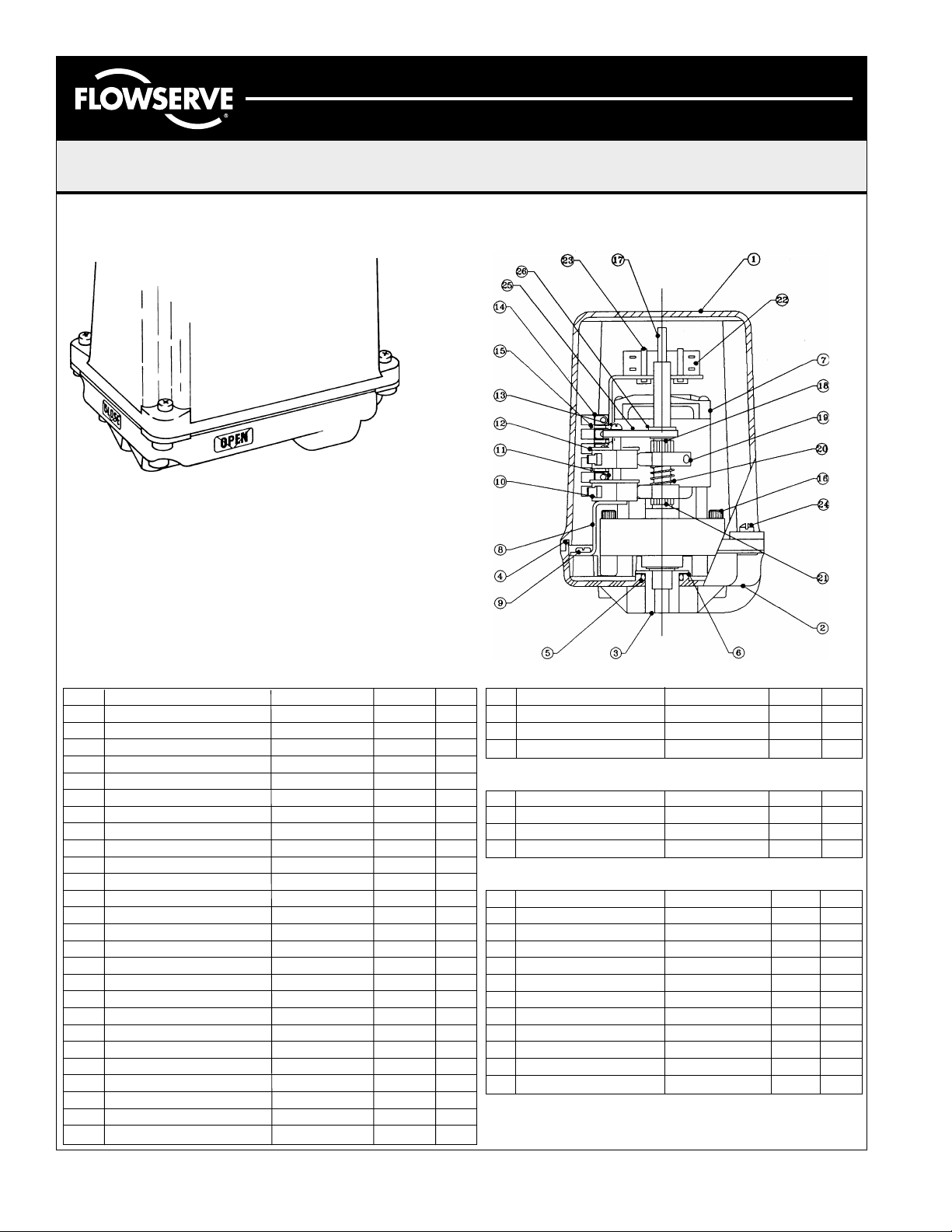
Parts & Materials CENTURA CPL Series
COMMON PARTS RELATED TO ALL ACTUATORS
NO. ITEM MATERIAL P/N QTY
1 Cover Zytel 106451 1
2 Base Zytel 106452 1
3 Output Adapter Steel/Plated 106453 1
4 ‘O’-ring Cover N674-70 Nitrile 106751 1
5 ‘O’-ring Base N674-70 Nitrile 102262 1
6 Shim Bearing Steel 106759 1
8 Switch Mounting Bracket Steel/Plated 107139 1
9 8-32UNCx3/8" Pan Head Steel/Plated 106755 3
10 Micro Switch with Leaf Plastic/Steel 105720 2
11 3/16" High Spacer Nylon 105679 6
12 Switch Insulator Gasket Vulcanized Fiber 103675 3
13 4-40UNCx1-1/2" Phillips Hd. Steel/Plated 108349 2
14 6 Position Terminal Strip Plastic/Steel 103997 1
2 Screw Marker Strip Plastic 103996 1
15 3-48UNCx1/2" Pan Head Steel/Plated 104837 2
17 Camshaft Steel/Plated 107005 1
18 Large 4-Deg. Spline Shaft Plastic 103571 1
1/16" Dia. Roll Pin Spring Steel 103621 1
19 4-Deg. Quick Set Cam Plastic 105655 2
20 Switch Spring Spring Steel 103714 1
21 Small 4-Deg. Spline Shaft Plastic 103572 1
1/16" Dia. Roll Pin Spring Steel 103621 1
23 Ty-Rap Cable Tie Plastic 106574 2
24 10-24x5/8" Captive Screw Stainless Steel X00360 4
25 Switch Support Bracket Aluminum 108997 1
26 3/8" Pop in Bearing Plastic 108998 1
ADDITIONAL PARTS SPECIFIC TO 115VAC 100IN-LBS.
NO. ITEM MATERIAL P/N QTY
7 115VAC PSC Gear Motor Steel/Copper 106617 1
16 6-32UNCx1/16"Pan Head Steel/Plated 106753 2
22 Capacitor Film Wrapped 107128 1
ADDITIONAL PARTS SPECIFIC TO 115VAC 225IN-LBS.
NO. ITEM MATERIAL P/N QTY
7 115VAC PSC Gear Motor Steel/Copper 106616 1
16 10-24UNCx1-5/8”Soc. Hd. Steel/Plated 106754 4
22 Capacitor Film Wrapped 107120 1
ADDITIONAL COMMON PARTS ** NOT SHOWN **
NO. ITEM MATERIAL P/N QTY
8-32UNC Ground screw Steel/Plated Green 103627 1
#8 Cup Washer Brass 105626 1
3/4” NPT Conduit Plug Plastic 103685 1
115VAC Wiring Harness Copper/Plastic 106749 1
Nameplate Mylar 106613 1
Flowserve Logo Sticker Mylar 106612 1
Cam Adjustment Sticker Mylar 105757 1
Switch I.D. Sticker Mylar 107135 1
Open/Close Stickers Mylar 106186 1
Position Indication Sticker Mylar 106187 1
115VAC Schematic Sticker Mylar 106758 1
LME0009-1 (Auto-39) 04/03
©
2003, Flowserve Corporation, Printed in USA
Page 2 of 4
Page 3

Automax Valve Automation Systems
3-Position Control/Dribble Control
Installation, Operation and Maintenance Instructions
SR Limit Switch Method
Flowserve Corporation 1350 N. Mountain Springs Parkway Phone: 801 489 8611
Flow Control Division Springville, Utah 84663-3004 Facsimile: 801 489 2228
www.flowserve.com
Troubleshooting
Problem:
There is power to the unit, but it does not respond.
Solution:
Check the nameplate to see that the correct voltage has
been applied.
Check the wiring to see that it is per the wiring schematic.
Check the limit switches to see if they are in the normal
operating range.
Problem:
Power is getting to the motor, but it merely hums.
Solution:
Check to see that the proper voltage is applied.
Make sure all the connections are tight.
Check to see that CW and CCW power connections are not
powered at the same time.
Reversible A. C. Actuator
SYMBOLS & DESCRIPTIONS
1. WHITE - Motor Common.
2. BLUE - Full CW Position
Indic ator
3. BLACK - AC Hi will Turn
Actua tor CW.
4. YELLOW - Full CCW
Position Indicator.
5. RED - AC Hi will Turn
Actuator CCW.
TERMINAL
STRIP
Reversible D. C. Actuator
SYMBOLS & DESCRIPTIONS
1. RED - DC+ (CW)
2. BLACK - DC- (CW)
3. BROWN - DC+ (CCW)
4. WHITE - DC- (CCW)
Reversible A. C. Actuator with 2 extra switches
NO - Normally Open
NC - Normally Closed
C - Common
NO - Normally Open
NO - Normally Open
NC - Normally Closed
NC - Normally Closed
C - Common
C - Common
Problem:
The actuator performs erratically.
Solution:
Check to see that the actuator is not stalling.
Check the ambient temperature rating. The permanent split
capacitor units are equipped with thermal cut-outs. Excessive
temperatures and cycle frequencies may heat the motor up and
the thermal cut-out turns it off.
Wiring Diagrams
Notes:
1. Consult factory when wiring multiple actuators in series or
parallel, serious damage may result.
2. Wiring diagrams show internal wire connections and
suggested customer connection for proper use. Switches
shown in "customer wiring" are for illustration only and are
not supplied with the actuator.
LME0009-1 (Auto-39) 04/03
©
2003, Flowserve Corporation, Printed in USA
SYMBOLS & DESCRIPTIONS
1. WHITE - Motor Common.
2. BLUE - Full CW Position
Indicator.
3. BLACK - AC Hi will Turn
Actuator CW.
4. YELLOW - Full CCW
Position Indicator.
5. RED - AC Hi will Turn
Actuator CCW.
6. ORANGE - Switch Common.
Reversible A. C. Actuator wired for 3 position
SYMBOLS & DESCRIPTIONS
1. WHITE - Motor Common.
2. YELLOW - AC Hi will Turn
Actua tor to M ID.
4. BLACK - AC Hi will Turn
Actua tor CW.
6. RED - AC Hi will Turn
Actuator CCW.
NO - Normally Open
NC - Normally Closed
C - Common
NO - Normally Open
NC - Normally Closed
C - Common
Page 3 of 4
Page 4

Automax Valve Automation Systems
3-Position Control/Dribble Control
Installation, Operation and Maintenance Instructions
Flowserve Corporation 1350 N. Mountain Springs Parkway Phone: 801 489 8611
Flow Control Division Springville, Utah 84663-3004 Facsimile: 801 489 2228
www.flowserve.com
Typical Actuator Specifications
Action Reversible
Supply Voltages AC: +/ 115VAC (1 Ph)
10% 230VAC (1 Ph)
50/60Hz 24VAC (1 Ph)
DC: 12VDC
24VDC
Temperature Rating -20°F (-28°C) to 160°F (70°C)
Enclosure Ratings / Device Testing CSA Enclosure 4
NEMA 4, 4X
89/336/EEC Directive for CE Marking
Range of Operation 0° to 180°
AC Motor Thermal Protection Automatically resetting
Motor Types AC: Permanent Split Capacitor
DC: Brush
Travel and Aux. Switches SPDT, Form C 15 amp 125 1/2 HP 10 amp
250VAC, 1/2 amp 125 VDC
Conduit Connections (1) 3/4-14 NPT
Corrosion Protection Enclosure: Zytel engineered resin
Cover Screws: Stainless Steel
Output Shaft: Dacromet Coating
Terminal Strip Hookup 300V, 30A, 12-26 AWG
Lubrication Permanently lubricated
Gear Train Heat treated alloy steel, rated to stall torque
SR Limit Switch Method
Note: The above ratings may change depending on model configurations and options provided.
Products may differ as the result of the Company policy of continuous product improvement.
Actuator Model
CPL1 CPL2
Cycle Times
Sec/90°
56
34
34
87
100 225 Torque (in-lbs)
11 25 Torque (Nm)
4 5 Weights Lbs (kg.)
1. Cycle times are approximate under no load conditions and may vary slightly under actual
operating conditions.
2. Duty cycles are rated at 70°F. The duty rates may be less under loaded conditions.
3. Do not lock up DC motors.
LME0009-1 (Auto-39) 04/03
©
2003, Flowserve Corporation, Printed in USA
Opt.
Motor
Desig.
Std 115 50 0.3 0.5 .04 0.5
B 12 100 1 1.6 * *
C 24 100 0.5 0.8 * *
D 230 50 0.11 0.18 0.12 0.2
Motor
Voltage
Duty
Cycle
(%)
Run Current
(amp)
CPL1 CPL2 CPL1 CPL2
Locked Rotor
(amp)
Page 4 of 4
 Loading...