

Page 1
Experience In Motion
Circpac MD
Split Segmented
Circumferential Gas Seal
Installation
Instructions
Page 2

1 Equipment Check and Seal Preparation
1.1 Refer to Figure 1 for sleeve/shaft and equipment requirements.
1.2 The equipment sleeve/shaft must be clean and free of any burrs, nicks or scratches.
1.3 Checksealassemblydrawingforspecicequipmentrequirements,reference
dimensions, special instructions, piping connections, and materials of construction.
Figure 1
Seal chamber squareness to the shaft
centerline should be within 0.25 mm per
25 mm shaft diameter (0.010” per 1” shaft
diameter). Seal chamber face surface
nishshouldbe125RMSorbetter.
1.4 Segmented rings have matched joints and must be mated together per the segment
numbering scheme shown in Figure 2 for 3 segment rings. During assembly, keep all
numbers facing the same direction. The polished side is a sealing surface and should
be handled carefully.
Note: Do not use grease or other lubricants on segmented carbon rings, housing,
or shaft.
1.5 Use caution when handling heavy gland ring halves. Maneuver and support large
parts carefully to avoid personal injury and/or damage to segmented rings.
Shaft runout should not exceed 0.10 mm
(0.004”)FIM.Shaftsurfacenishshould
be 16 RMS or better.
Figure 2
Polished Face
2
2
Back Front
Drive Pin
2
2
Page 3

2 Seal Installation (Split Housing Designs)
Seal components are assembled in the following order: housing gasket (if separate),
bottom housing half, segmented rings, and upper housing half. Housing gasketing, housing
weight support, centering methods, and multiple ring sequencing should be considered
prior to starting.
Figure 3
2.1 The housing gasket may be supplied split
and bonded to the housing halves or as a
solid ring, depending on gasket type. If the
gasket is already bonded to the housing
halves, no extra preparation is necessary.
Otherwise, with a sharp cutting instrument,
carefully cut the gasket tangential to the
gasket ID with a 45° bias in the thickness, as
shown in Figure 3. At the cut joint, bend the
gaskettotaroundtheshaft.Positionthe
gasket near the equipment face.
Figure 4
2.2 The housing half with drive pin slots at the
joint surface is the bottom half of the housing
ringandisinstalledrst.Orientthelower
housing half toward the equipment in the
direction indicated on the seal assembly
drawing or marked on the housing. Support
the lower half of the housing on the
equipment with loosely engaged bolts or
studs such that the gasket area is accessible
and the segmented ring grooves are fully
exposed.
2.3 If the seal is designed with multiple
segmented rings, start at the housing end
that will be obstructed by additional rings.
Complete each ring before starting the next.
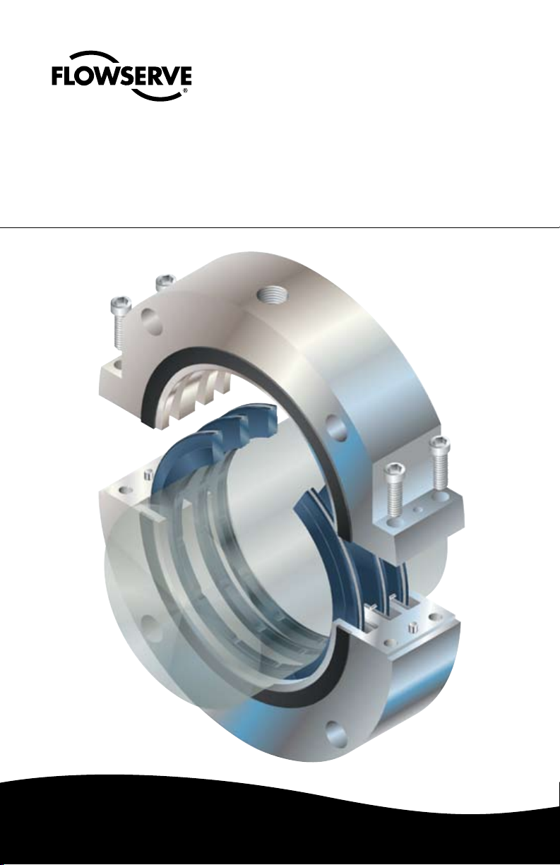
2.4 Feed the garter spring into the ring groove
in the lower housing half. Leave an equal
amount of spring hanging out on each side.
Figure 5
3
Page 4
2.5 Select a ring segment that does not
havethedrivepin.Positionitoverthe
groove in the lower housing half. Make
sure the numbered side faces the pin slot
in the housing joint surface. Rotate the
rstsegmentintothegroove.Thegarter
spring should be on the outside diameter
of the segment.
2.6 For 3 segment rings, select the other ring
segment that does not have the drive
pin, keeping the numbered ends in order
as described in Figure 2. Make sure the
numbered side faces the pin slot in the
housing joint surface. Rotate the second
segment into the groove such that the
segment ends are exposed. The garter
spring should be on the outside diameter
of both segments.
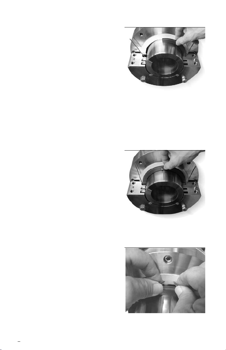
2.7 Completetheringwiththenalsegment,
again with the numbered side facing the
pin slot in the housing joint surface. There
will be a gap between one of the joints.
Figure 6
Figure 7
2.8 Carefully hook the ends of the garter
spring within the groove in the segmented
ring. Do not overstretch the spring.
4
Figure 8
Page 5

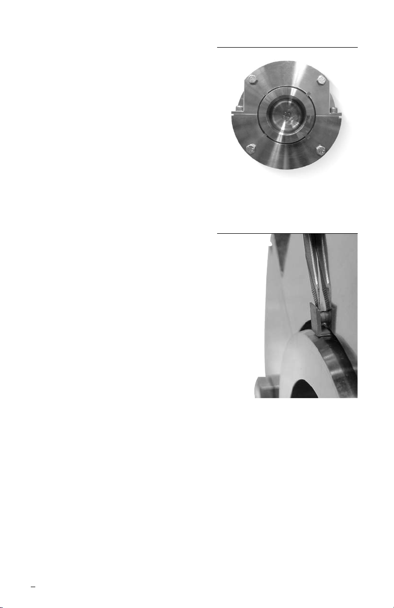
2.9 Rotate the ring assembly until the drive pin
engages the pin slot at the housing joint.
2.10 Repeat steps 2.3-2.9 with all segmented
rings. Figure 10 shows a completed 3 ring
assembly.
Figure 9
Figure 10
2.11 Carefully and slowly lower the upper
housing half onto the lower housing half.
Install the housing joint cap screws and
tighten to 14 N-m (10 ft-lbs) minimum.
2.12 If necessary, complete the housing gasket
installation as shown on the assembly
drawing. A general purpose adhesive may
be used to hold the gasket in place. Take
care not to contaminate the shaft or rings.
Figure 11
5
Page 6
2.13 Center the housing assembly on the shaft
as required. If centering devices are used,
release any housing supports so that the
centering devices are properly engaged on
the shaft.
2.14 Evenly tighten the housing to the
equipment until the face gasket is fully
compressed and the housing is squarely
seated. Torque housing bolts to 34 N-m
(25 ft-lbs) minimum.
Figure 12
2.15 Remove centering devices, if applicable.
2.16 Connect piping if required.
Figure 13
6
Page 7

3 Seal Installation (Non-split Housing Designs)
3.1 Circpac MD seals with non-split housings are pre-assembled at the factory for
cartridge installation. Unless otherwise indicated on the seal assembly drawing, an
installation plug is installed in the seal bore to guide the rings onto the equipment
shaft during installation. If no installation plug is used, the shaft/sleeve end must
have a smooth, 30 degree by 3.2 mm (0.125”) lead-in chamfer to ramp the rings onto
the shaft.
3.2 Check that the housing gasket is properly installed at the face of the housing.
3.3 Carefully slide the housing assembly onto the shaft. The installation plug should be
displaced by the shaft and fall away once the last ring has mounted the shaft.
3.4 Center the housing assembly on the shaft as required.
3.5 Evenly tighten the housing to the equipment until the face gasket is fully compressed
and the housing is squarely seated. Torque housing bolts to 34 N-m (25 ft-lbs)
minimum.
3.6 Remove centering devices, if applicable.
3.7 Connect piping if required.
4 Operational Recommendations
For dual seals, barrier pressure and other controls should be energized prior to starting the
equipment or introducing product. Likewise, do not remove pressure or controls until the
equipment has been fully shut down and vented.
The Circpac MD is designed to operate with clean air or nitrogen barrier gas. Check seal
assembly drawing for recommended barrier pressure setting.
For special problems encountered during installation, contact your nearest Flowserve Sales
and Service Representative or Authorized Distributor.
5 Repairs
This product is a precision sealing device. The design and dimension tolerances are critical
to seal performance. Only parts supplied by Flowserve should be used to repair a seal. To
order replacement parts, refer to the part code and B/M number. A spare backup seal
should be stocked to reduce repair time.
When seals are returned to Flowserve for repair, decontaminate the seal assembly and
include an order marked "Repair or Replace." A signed certicate of decontamination
must be attached. A Material Safety Data Sheet (MSDS) must be enclosed for any
product that came in contact with the seal. The seal assembly will be inspected and, if
repairable, it will be rebuilt, tested, and returned.
7
Page 8

TO REORDER REFER TO
flowserve.com
USA and Canada
Kalamazoo, Michigan USA
Telephone: 1 269 381 2650
Telefax: 1 269 382 8726
Europe, Middle East, Africa
Roosendaal, the Netherlands
Telephone: 31 165 581400
Telefax: 31 165 554590
Asia Pacific
Singapore
Telephone: 65 6544 6800
Telefax: 65 6214 0541
Latin America
Mexico City
Telephone: 52 55 5567 7170
Telefax: 52 55 5567 4224
B/M #
F.O
.
FIS153eng REV 01/03 Printed in USA
To find your local Flowserve representative
and find out more about Flowserve Corporation,
visit www.flowserve.com
Flowserve Corporation has established industry leadership in the design and manufacture of its products. When
properly selected, this Flowserve product is designed to perform its intended function safely during its useful life.
However, the purchaser or user of Flowserve products should be aware that Flowserve products might be used
in numerous applications under a wide variety of industrial service conditions. Although Flowserve can provide
general guidelines, it cannot provide specific data and warnings for all possible applications. The purchaser/user
must therefore assume the ultimate responsibility for the proper sizing and selection, installation, operation, and
maintenance of Flowserve products. The purchaser/user should read and understand the Installation Instructions
included with the product, and train its employees and contractors in the safe use of Flowserve products in connection
with the specific application.
While the information and specifications contained in this literature are believed to be accurate, they are supplied for
informative purposes only and should not be considered certified or as a guarantee of satisfactory results by reliance
thereon. Nothing contained herein is to be construed as a warranty or guarantee, express or implied, regarding any
matter with respect to this product. Because Flowserve is continually improving and upgrading its product design,
the specifications, dimensions and information contained herein are subject to change without notice. Should any
question arise concerning these provisions, the purchaser/user should contact Flowserve Corporation at any one of
its worldwide operations or offices.
© Flowserve Corporation (2011)
 Loading...