

Page 1
USER INSTRUCTIONS
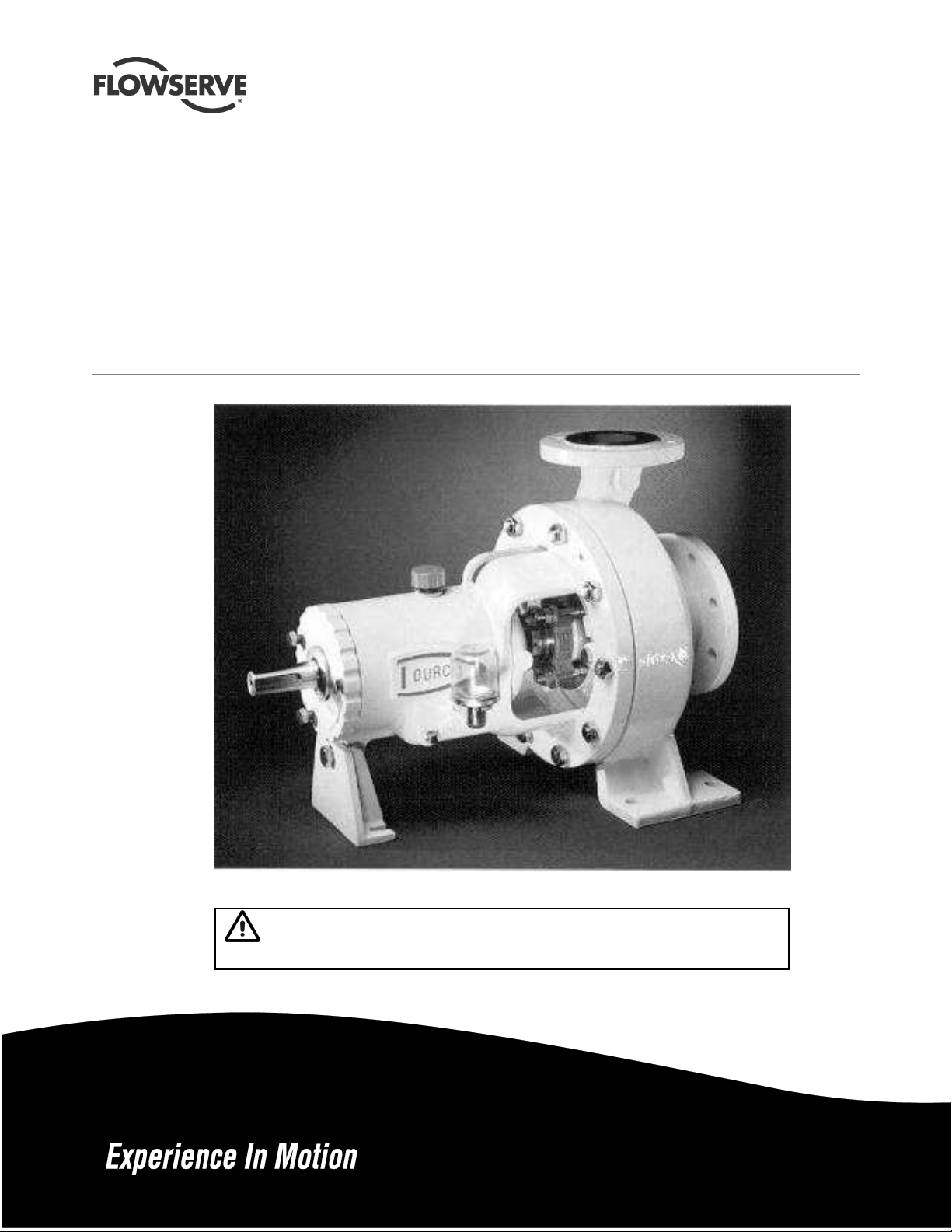
Chemstar standard and repeller
pumps
Frame mounted, heavy-duty, centrifugal chemical process
pumps
PCN=71569185 02-10 (E) (Based on ISO-30-E.)
Original instructions.
Installation
Operation
Maintenance
These instructions must be read prior to installing,
operating, using and maintaining this equipment.
Page 2

CHEMSTAR USER INSTRUCTIONS ENGLISH 71569185 02-10
CONTENTS
Page
1 INTRODUCTION AND SAFETY............................ 3
1.1 General ...........................................................3
1.2 CE marking and approvals..............................3
1.3 Disclaimer .......................................................3
1.4 Copyright.........................................................3
1.5 Duty conditions................................................ 3
1.6 Safety..............................................................4
1.7 Nameplate and safety labels...........................7
1.8 Specific machine performance........................8
1.9 Noise level.......................................................8
2 TRANSPORT AND STORAGE..............................9
2.1 Consignment receipt and unpacking...............9
2.2 Handling..........................................................9
2.3 Lifting...............................................................9
2.4 Storage............................................................9
2.5 Recycling and end of product life....................9
3 DESCRIPTION ......................................................9
3.1 Configurations.................................................9
3.2 Name nomenclature........................................9
3.3 Design of major parts....................................10
3.4 Performance and operating limits ................. 10
4 INSTALLATION....................................................10
4.1 Location.........................................................10
4.2 Part assemblies.............................................10
4.3 Foundation .................................................... 11
4.4 Grouting ........................................................ 11
4.5 Initial alignment ............................................. 11
4.6 Piping ............................................................12
4.7 Final shaft alignment check ..........................15
4.8 Electrical connections ...................................15
4.9 Protection systems........................................15
5 COMMISSIONING, START-UP, OPERATION
AND SHUTDOWN ...........................................15
5.1 Pre-commissioning procedure ......................15
5.2 Pump lubricants ............................................16
5.3 Impeller clearance.........................................17
5.4 Direction of rotation.......................................17
5.5 Guarding .......................................................18
5.6 Priming and auxiliary supplies ...................... 18
5.7 Starting the pump..........................................18
5.8 Running the pump.........................................18
5.9 Stopping and shutdown (all series)...............19
5.10 Hydraulic, mechanical and electrical duty...20
6 MAINTENANCE ...................................................20
6.1 General..........................................................20
6.2 Maintenance schedule...................................21
6.3 Spare parts.....................................................22
6.4 Recommended spares...................................23
6.5 Tools required ................................................23
6.6 Fastener torques............................................24
6.7 Setting impeller clearance .............................24
6.8 Disassembly ..................................................25
6.9 Examination of parts......................................27
6.10 Assembly .....................................................27
6.11 Sealing arrangements..................................32
7 FAULTS; CAUSES AND REMEDIES...................33
8 PARTS LISTS AND DRAWINGS .........................35
8.1 Chemstar – Groups A, B and C.....................35
8.2 Chemstar – Group D......................................36
8.3 Chemstar repeller pump – Group B and C
9 CERTIFICATION..................................................40
10 OTHER RELEVANT DOCUMENTATION
– large bore repeller cover
– bolt-on stuffing box ...................................37
8.4 Chemstar repeller pump – Group B and C
– small bore repeller cover
– integral stuffing box ..................................38
8.5 Chemstar repeller pump – Group B and C
with bolt-on stuffing box – exploded view....39
8.6 General arrangement drawing.......................40
AND MANUALS................................................40
10.1 Supplementary User Instruction manuals....40
10.2 Change notes ..............................................40
10.3 Additional sources of information.................40
Page
Page 2 of 44 flowserve.com
Page 3
CHEMSTAR USER INSTRUCTIONS ENGLISH 71569185 02-10
1 INTRODUCTION AND SAFETY
1.1 General
These instructions must always be kept
close to the product's operating location or
directly with the product.
Flowserve products are designed, developed and
manufactured with state-of-the-art technologies in
modern facilities. The unit is produced with great
care and commitment to continuous quality control,
utilising sophisticated quality techniques, and safety
requirements.
Flowserve is committed to continuous quality
improvement and being at service for any further
information about the product in its installation and
operation or about its support products, repair and
diagnostic services.
These instructions are intended to facilitate familiarization
with the product and its permitted use. Operating the
product in compliance with these instructions is important
to help ensure reliability in service and avoid risks. The
instructions may not take into account local regulations;
ensure such regulations are observed by all, including
those installing the product. Always coordinate repair
activity with operations personnel, and follow all plant
safety requirements and applicable safety and health
laws and regulations.
These instructions must be read prior to
installing, operating, using and maintaining the
equipment in any region worldwide. The
equipment must not be put into service until all
the conditions relating to safety, noted in the
instructions, have been met. Failure to follow and
apply the present user instructions is considered
to be misuse. Personal injury, product damage,
delay or failure caused by misuse are not covered
by the Flowserve warranty.
1.2 CE marking and approvals
It is a legal requirement that machinery and equipment
put into service within certain regions of the world shall
conform with the applicable CE Marking Directives
covering Machinery and, where applicable, Low Voltage
Equipment, Electromagnetic Compatibility (EMC),
Pressure Equipment Directive (PED) and Equipment for
Potentially Explosive Atmospheres (ATEX).
Where applicable, the Directives and any additional
Approvals, cover important safety aspects relating to
machinery and equipment and the satisfactory provision
of technical documents and safety instructions.
Where applicable this document incorporates
information relevant to these Directives and Approvals.
To confirm the Approvals applying and if the product is
CE marked, check the serial number plate markings
and the Certification. (See section 9, Certification.)
1.3 Disclaimer
Information in these User Instructions is believed
to be reliable. In spite of all the efforts of
Flowserve Corporation to provide sound and all
necessary information the content of this manual
may appear insufficient and is not guaranteed by
Flowserve as to its completeness or accuracy.
Flowserve manufactures products to exacting
International Quality Management System Standards as
certified and audited by external Quality Assurance
organisations. Genuine parts and accessories have
been designed, tested and incorporated into the
products to help ensure their continued product quality
and performance in use. As Flowserve cannot test
parts and accessories sourced from other vendors the
incorrect incorporation of such parts and accessories
may adversely affect the performance and safety
features of the products. The failure to properly select,
install or use authorised Flowserve parts and
accessories is considered to be misuse. Damage or
failure caused by misuse is not covered by the
Flowserve warranty. In addition, any modification of
Flowserve products or removal of original components
may impair the safety of these products in their use.
1.4 Copyright
All rights reserved. No part of these instructions may
be reproduced, stored in a retrieval system or
transmitted in any form or by any means without prior
permission of Flowserve Pump Division.
1.5 Duty conditions
This product has been selected to meet the
specifications of your purchaser order. The
acknowledgement of these conditions has been sent
separately to the Purchaser. A copy should be kept
with these instructions.
The product must not be operated beyond
the parameters specified for the application.
If there is any doubt as to the suitability of the
product for the application intended, contact
Flowserve for advice, quoting the serial number.
If the conditions of service on your purchase order are
going to be changed (for example liquid pumped,
temperature or duty) it is requested that the user seeks
the written agreement of Flowserve before start up.
Page 3 of 44 flowserve.com
Page 4
CHEMSTAR USER INSTRUCTIONS ENGLISH 71569185 02-10
1.6 Safety
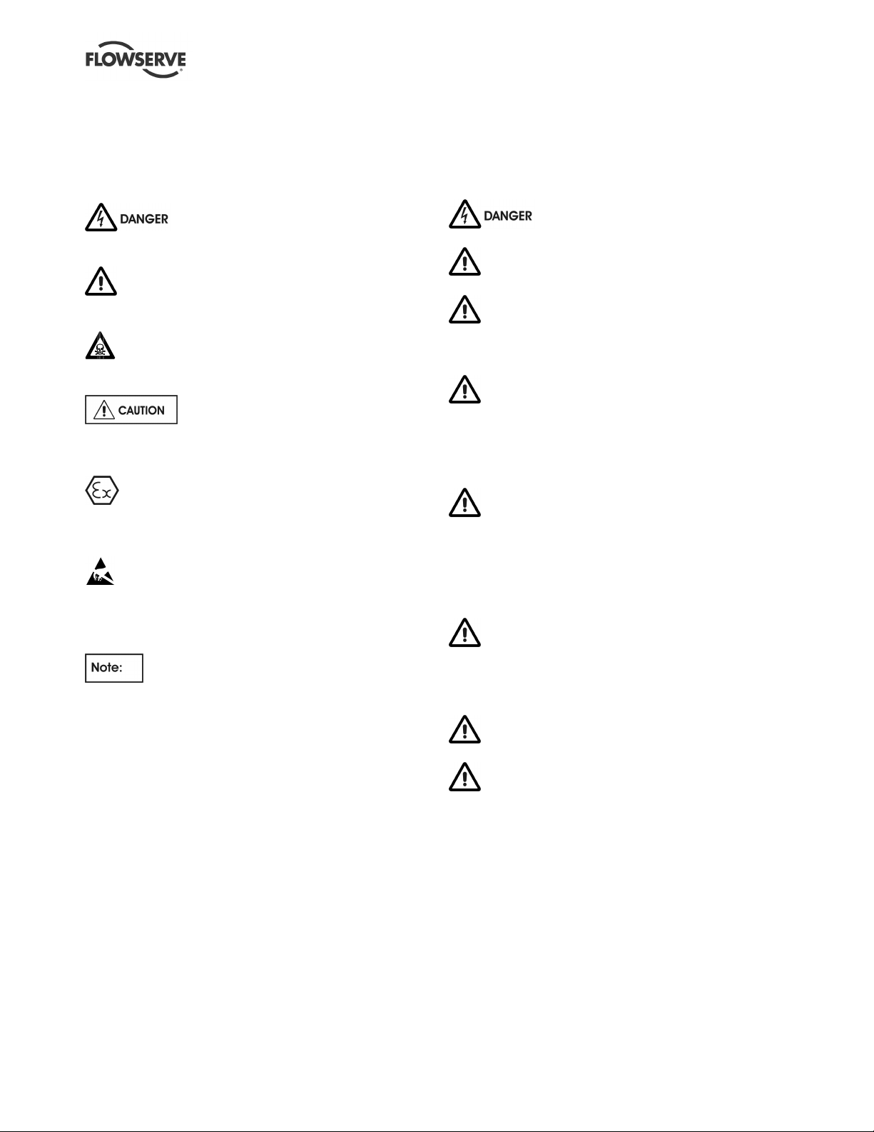
1.6.1 Summary of safety markings
These User Instructions contain specific safety
markings where non-observance of an instruction would
cause hazards. The specific safety markings are:
This symbol indicates electrical safety
instructions where non-compliance will involve a high
risk to personal safety or the loss of life.
This symbol indicates safety instructions where
non-compliance would affect personal safety and could
result in loss of life.
This symbol indicates “hazardous and toxic fluid”
safety instructions where non-compliance would affect
personal safety and could result in loss of life.
This symbol indicates safety instructions
where non-compliance will involve some risk to safe
operation and personal safety and would damage the
equipment or property.
This symbol indicates explosive atmosphere zone
marking according to ATEX. It is used in safety
instructions where non-compliance in the hazardous
area would cause the risk of an explosion.
This symbol is used in safety instructions to
remind not to rub non-metallic surfaces with a dry
cloth; ensure the cloth is damp. It is used in safety
instructions where non-compliance in the hazardous
area would cause the risk of an explosion.
This sign is not a safety symbol but indicates
an important instruction in the assembly process.
1.6.2 Personnel qualification and training
All personnel involved in the operation, installation,
inspection and maintenance of the unit must be
qualified to carry out the work involved. If the personnel
in question do not already possess the necessary
knowledge and skill, appropriate training and instruction
must be provided. If required the operator may
commission the manufacturer/supplier to provide
applicable training.
Always coordinate repair activity with operations and
health and safety personnel, and follow all plant
safety requirements and applicable safety and health
laws and regulations.
1.6.3 Safety action
This is a summary of conditions and actions to help
prevent injury to personnel and damage to the
environment and to equipment. For products used
in potentially explosive atmospheres section 1.6.4
also applies.
NEVER DO MAINTENANCE WORK
WHEN THE UNIT IS CONNECTED TO POWER
GUARDS MUST NOT BE REMOVED WHILE
THE PUMP IS OPERATIONAL
DRAIN THE PUMP AND ISOLATE PIPEWORK
BEFORE DISMANTLING THE PUMP
The appropriate safety precautions should be taken
where the pumped liquids are hazardous.
FLUORO-ELASTOMERS (When fitted.)
When a pump has experienced temperatures over
250 ºC (482 ºF), partial decomposition of fluoroelastomers (example: Viton) will occur. In this
condition these are extremely dangerous and skin
contact must be avoided.
HANDLING COMPONENTS
Many precision parts have sharp corners and the
wearing of appropriate safety gloves and equipment
is required when handling these components. To lift
heavy pieces above 25 kg (55 lb) use a crane
appropriate for the mass and in accordance with
current local regulations.
THERMAL SHOCK
Rapid changes in the temperature of the liquid within
the pump can cause thermal shock, which can result
in damage or breakage of components and should be
avoided.
NEVER APPLY HEAT TO REMOVE IMPELLER
Trapped lubricant or vapour could cause an explosion.
HOT (and cold) PARTS
If hot or freezing components or auxiliary heating
supplies can present a danger to operators and
persons entering the immediate area action must be
taken to avoid accidental contact. If complete
protection is not possible, the machine access must
be limited to maintenance staff only, with clear visual
warnings and indicators to those entering the
immediate area. Note: bearing housings must not be
insulated and drive motors and bearings may be hot.
If the temperature is greater than 80 ºC (175 ºF) or
below -5 ºC (20 ºF) in a restricted zone, or exceeds
local regulations, action as above shall be taken.
Page 4 of 44 flowserve.com
Page 5
CHEMSTAR USER INSTRUCTIONS ENGLISH 71569185 02-10
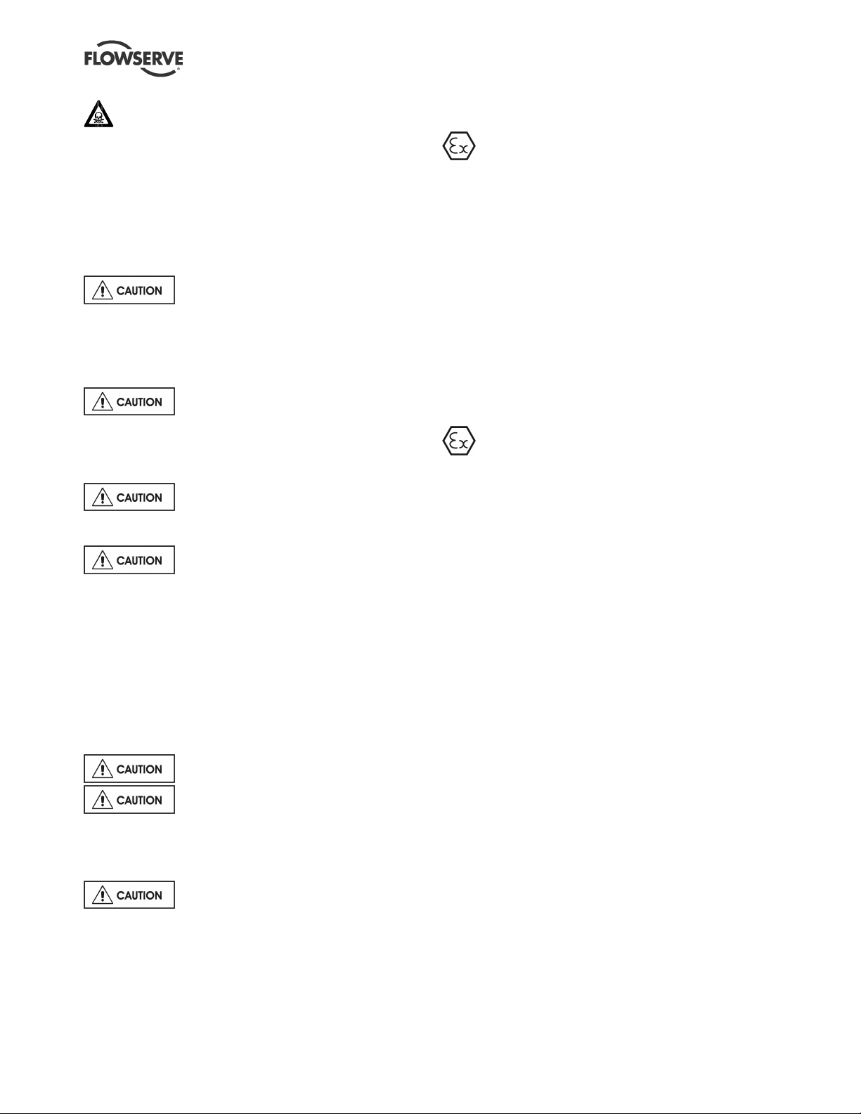
1.6.4 Products used in potentially explosive
HAZARDOUS LIQUIDS
When the pump is handling hazardous liquids care
must be taken to avoid exposure to the liquid by
appropriate siting of the pump, limiting personnel
access and by operator training. If the liquid is
flammable and or explosive, strict safety procedures
must be applied.
Gland packing must not be used when pumping
hazardous liquids.
PREVENT EXCESSIVE EXTERNAL
PIPE LOAD
Do not use pump as a support for piping. Do not mount
expansion joints, unless allowed by Flowserve in writing,
so that their force, due to internal pressure, acts on the
pump flange.
ONLY CHECK DIRECTION OF
MOTOR ROTATION WITH COUPLING ELEMENT/
PINS REMOVED
Starting in reverse direction of rotation will damage the
pump.
ENSURE CORRECT LUBRICATION
(See section 5, Commissioning, startup, operation and
shutdown.)
START THE PUMP WITH OUTLET
VALVE PART OPENED
(Unless otherwise instructed at a specific point in the
User Instructions.)
This is recommended to minimize the risk of
overloading and damaging the pump or motor at full or
zero flow. Pumps may be started with the valve further
open only on installations where this situation cannot
occur. The pump outlet control valve may need to be
adjusted to comply with the duty following the run-up
process. (See section 5, Commissioning start-up,
operation and shutdown.)
NEVER RUN THE PUMP DRY
INLET VALVES TO BE FULLY OPEN
WHEN PUMP IS RUNNING
Running the pump at zero flow or below the
recommended minimum flow continuously will cause
damage to the pump and mechanical seal.
atmospheres
Measures are required to:
• Avoid excess temperature
• Prevent build up of explosive mixtures
• Prevent the generation of sparks
• Prevent leakages
• Maintain the pump to avoid hazard
The following instructions for pumps and pump units
when installed in potentially explosive atmospheres
must be followed to help ensure explosion protection.
For ATEX, both electrical and non-electrical equipment
must meet the requirements of European Directive
94/9/EC. Always observe the regional legal Ex
requirements eg Ex electrical items outside the EU may
be required certified to other than ATEX eg IECEx, UL.
1.6.4.1 Scope of compliance
Use equipment only in the zone for which it is
appropriate. Always check that the driver, drive
coupling assembly, seal and pump equipment are
suitably rated and/or certified for the classification of the
specific atmosphere in which they are to be installed.
Where Flowserve has supplied only the bare shaft
pump, the Ex rating applies only to the pump. The
party responsible for assembling the ATEX pump set
shall select the coupling, driver and any additional
equipment, with the necessary CE Certificate/
Declaration of Conformity establishing it is suitable for
the area in which it is to be installed.
The output from a variable frequency drive (VFD) can
cause additional heating effects in the motor and so,
for pump sets with a VFD, the ATEX Certification for
the motor must state that it is covers the situation
where electrical supply is from the VFD. This
particular requirement still applies even if the VFD is
in a safe area.
DO NOT RUN THE PUMP AT
ABNORMALLY HIGH OR LOW FLOW RATES
Operating at a flow rate higher than normal or at a flow
rate with no back pressure on the pump may overload
the motor and cause cavitation. Low flow rates may
cause a reduction in pump/bearing life, overheating of
the pump, instability and cavitation/vibration.
Page 5 of 44 flowserve.com
Page 6
CHEMSTAR USER INSTRUCTIONS ENGLISH 71569185 02-10
1.6.4.2 Marking
An example of ATEX equipment marking is shown
below. The actual classification of the pump will be
engraved on the nameplate.
II 2 GD c IIC 135 ºC (T4)
Equipment Group
I = Mining
II = Non-mining
Category
2 or M2 = high level protection
3 = normal level of protection
Gas and/or dust
G = Gas
D = Dust
c = Constructional safety
(in accordance with EN13463-5)
Gas Group (Equipment Category 2 only)
IIA – Propane (typical)
IIB – Ethylene (typical)
IIC – Hydrogen (typical)
Maximum surface temperature (Temperature Class)
(see section 1.6.4.3.)
1.6.4.3 Avoiding excessive surface temperatures
ENSURE THE EQUIPMENT TEMPERATURE
CLASS IS SUITABLE FOR THE HAZARD ZONE
Pumps have a temperature class as stated in the
ATEX Ex rating on the nameplate. These are based
on a maximum ambient of 40 ºC (104 ºF); refer to
Flowserve for higher ambient temperatures.
The surface temperature on the pump is influenced
by the temperature of the liquid handled. The
maximum permissible liquid temperature depends on
the ATEX temperature class and must not exceed the
values in the table that follows:
Temperature class
to EN13463-1
T6
T5
T4
T3
T2
T1
* The table only takes the ATEX temperature class into consideration.
Pump design or material, as well as component design or material,
may further limit the maximum working temperature of the liquid.
Maximum surface
temperature permitted
85 °C (185 °F)
100 °C (212 °F)
135 °C (275 °F)
200 °C (392 °F)
300 °C (572 °F)
450 °C (842 °F)
Temperature limit of
liquid handled *
Consult Flowserve
Consult Flowserve
115 °C (239 °F) *
180 °C (356 °F) *
275 °C (527 °F) *
400 °C (752 °F) *
The temperature rise at the seals and bearings and
due to the minimum permitted flow rate is taken into
account in the temperatures stated.
The responsibility for compliance with the
specified maximum liquid temperature is with the
plant operator.
Temperature classification “Tx” is used when the liquid
temperature varies and when the pump is required to be
used in differently classified potentially explosive
atmospheres. In this case the user is responsible for
ensuring that the pump surface temperature does not
exceed that permitted in its actual installed location.
If an explosive atmosphere exists during the
installation, do not attempt to check the direction of
rotation by starting the pump unfilled. Even a short
run time may give a high temperature resulting from
contact between rotating and stationary components.
Where there is any risk of the pump being run against
a closed valve generating high liquid and casing
external surface temperatures, fit an external surface
temperature protection device.
Avoid mechanical, hydraulic or electrical overload by
using motor overload trips, a temperature or power
monitor and make routine vibration monitoring checks.
In dirty or dusty environments, make regular checks
and remove dirt from areas around close clearances,
bearing housings and motors.
1.6.4.4 Preventing the build up of explosive
mixtures
ENSURE THE PUMP IS PROPERLY FILLED
AND VENTED AND DOES NOT RUN DRY
Ensure the pump and relevant suction and discharge
pipeline system is totally filled with liquid at all times
during the pump operation, so that an explosive
atmosphere is prevented. In addition it is essential to
make sure that seal chambers, auxiliary shaft seal
systems and any heating and cooling systems are
properly filled.
If the operation of the system cannot avoid this
condition, fit an appropriate dry run protection device
(for example liquid detection or a power monitor).
To avoid potential hazards from fugitive emissions of
vapour or gas to atmosphere the surrounding area
must be well ventilated.
Page 6 of 44 flowserve.com
Page 7
CHEMSTAR USER INSTRUCTIONS ENGLISH 71569185 02-10
1.6.4.5 Preventing sparks
To prevent a potential hazard from mechanical
contact, the coupling guard must be non-sparking
and anti-static for Category 2.
To avoid the potential hazard from random induced
current generating a spark, the baseplate must be
properly grounded.
Avoid electrostatic charge: do not rub non-metallic
surfaces with a dry cloth; ensure cloth is damp.
The coupling must be selected to comply with 94/9/EC
and correct alignment must be maintained.
Additional requirement for metallic pumps on
non-metallic baseplates
When metallic components are fitted on a nonmetallic baseplate they must be individually earthed.
1.6.4.6 Preventing leakage
The pump must only be used to handle liquids
for which it has been approved to have the correct
corrosion resistance.
Avoid entrapment of liquid in the pump and associated
piping due to closing of suction and discharge valves,
which could cause dangerous excessive pressures to
occur if there is heat input to the liquid. This can occur if
the pump is stationary or running.
Bursting of liquid containing parts due to freezing
must be avoided by draining or protecting the pump
and ancillary systems.
Where there is the potential hazard of a loss of a seal
barrier fluid or external flush, the fluid must be monitored.
If leakage of liquid to atmosphere can result in a
hazard, install a liquid detection device
1.6.4.7 Maintenance to avoid the hazard
Where there is a risk from such tools or materials,
maintenance must be conducted in a safe area.
It is recommended that a maintenance plan and
schedule is adopted. (See section 6, Maintenance.)
1.7 Nameplate and safety labels
1.7.1 Nameplate
For details of nameplate, see the Declaration of
Conformity, or separate documentation included with
these User Instructions.
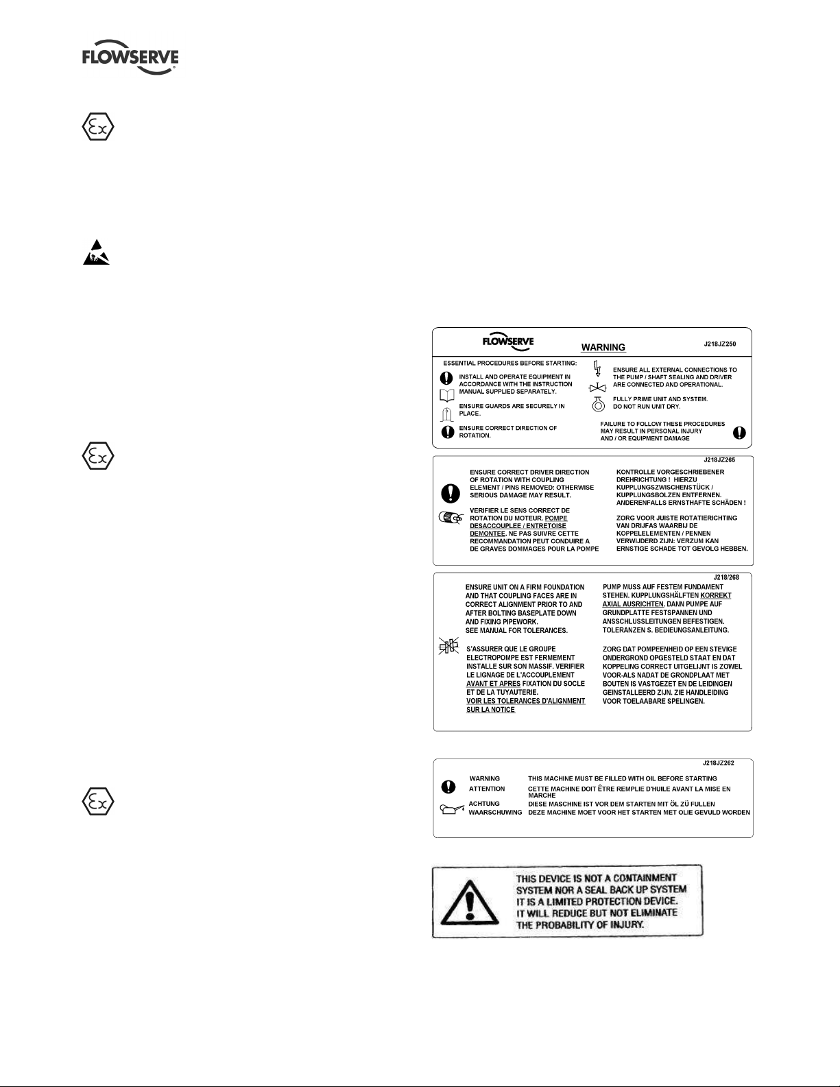
1.7.2 Safety labels
Oil lubricated units only:
CORRECT MAINTENANCE IS REQUIRED TO
AVOID POTENTIAL HAZARDS WHICH GIVE A
RISK OF EXPLOSION
Seal Guard units only:
The responsibility for compliance with maintenance
instructions is with the plant operator.
To avoid potential explosion hazards during
maintenance, the tools, cleaning and painting
materials used must not give rise to sparking or
adversely affect the ambient conditions.
Page 7 of 44 flowserve.com
Page 8
CHEMSTAR USER INSTRUCTIONS ENGLISH 71569185 02-10
1.8 Specific machine performance
For performance parameters see section 1.5, Duty
conditions. Where performance data has been supplied
separately to the purchaser these should be obtained
and retained with these User Instructions if required.
1.9 Noise level
Attention must be given to the exposure of personnel
to the noise, and local legislation will define when
guidance to personnel on noise limitation is required,
and when noise exposure reduction is mandatory.
This is typically 80 to 85 dBA.
The usual approach is to control the exposure time to
the noise or to enclose the machine to reduce emitted
sound. You may have already specified a limiting
noise level when the equipment was ordered,
however if no noise requirements were defined, then
attention is drawn to the following table to give an
indication of equipment noise level so that you can
take the appropriate action in your plant.
Pump noise level is dependent on a number of
Similarly the motor noise assumed in the “pump and
motor” noise is that typically expected from standard
and high efficiency motors when on load directly driving
the pump. Note that a motor driven by an inverter may
show an increased noise at some speeds.
If a pump unit only has been purchased for fitting with
your own driver then the “pump only” noise levels in the
table should be combined with the level for the driver
obtained from the supplier. Consult Flowserve or a
noise specialist if assistance is required in combining
the values.
It is recommended that where exposure approaches
the prescribed limit, then site noise measurements
should be made.
The values are in sound pressure level LpA at 1 m
(3.3 ft) from the machine, for “free field conditions
over a reflecting plane”.
For estimating sound power level LWA (re 1 pW) then
add 14 dBA to the sound pressure value.
operational factors, flow rate, pipework design and
acoustic characteristics of the building, and so the
values given are subject to a 3 dBA tolerance and
cannot be guaranteed.
Motor size
and speed
kW (hp)
<0.55(<0.75) 72 72 64 65 62 64 62 64
0.75 (1) 72 72 64 66 62 64 62 64
1.1 (1.5) 74 74 66 67 64 64 62 63
1.5 (2) 74 74 66 71 64 64 62 63
2.2 (3) 75 76 68 72 65 66 63 64
3 (4) 75 76 70 73 65 66 63 64
4 (5) 75 76 71 73 65 66 63 64
5.5 (7.5) 76 77 72 75 66 67 64 65
7.5 (10) 76 77 72 75 66 67 64 65
11(15) 80 81 76 78 70 71 68 69
15 (20) 80 81 76 78 70 71 68 69
18.5 (25) 81 81 77 78 71 71 69 71
22 (30) 81 81 77 79 71 71 69 71
30 (40) 83 83 79 81 73 73 71 73
37 (50) 83 83 79 81 73 73 71 73
45 (60) 86 86 82 84 76 76 74 76
55 (75) 86 86 82 84 76 76 74 76
75 (100) 87 87 83 85 77 77 75 77
90 (120) 87 88 83 85 77 78 75 78
110 (150) 89 90 85 87 79 80 77 80
150 (200) 89 90 85 87 79 80 77 80
Note: for 1 180 and 960 r/min reduce 1 450 r/min values by 2 dBA. For 880 and 720 r/min reduce 1 450 r/min values by 3 dBA.
3 550 r/min 2 900 r/min 1 750 r/min 1 450 r/min
Pump
only
Pump and
Typical sound pressure level LpA at 1 m reference 20 µPa, dBA
motor
Pump
only
Pump and
motor
Pump
only
Pump and
motor
Pump
only
Pump and
motor
Page 8 of 44 flowserve.com
Page 9

CHEMSTAR USER INSTRUCTIONS ENGLISH 71569185 02-10
2 TRANSPORT AND STORAGE
2.1 Consignment receipt and unpacking
Immediately after receipt of the equipment it must be
checked against the delivery/shipping documents for
its completeness and that there has been no damage
in transportation. Any shortage and/or damage must
be reported immediately to Flowserve and must be
received in writing within one month of receipt of the
equipment. Later claims cannot be accepted.
Check any crate, boxes or wrappings for any
accessories or spare parts that may be packed
separately with the equipment or attached to side
walls of the box or equipment.
Each product has a unique serial number. Check
that this number corresponds with that advised and
always quote this number in correspondence as well
as when ordering spare parts or further accessories.
2.2 Handling
Boxes, crates, pallets or cartons may be unloaded
using fork lift vehicles or slings dependent on their
size and construction.
2.3 Lifting
To avoid distortion, the pump unit
should be lifted as shown:
A crane must be used for all pump sets in
excess of 25 kg (55 lb). Fully trained personnel must
carry out lifting, in accordance with local regulations.
The driver weight is recorded on its nameplate.
2.4 Storage
Store the pump in a clean, dry location
away from vibration. Leave piping connection covers
in place to keep dirt and other foreign material out of
pump casing. Turn pump at intervals to prevent
brinelling of the bearings and the seal faces, if fitted,
from sticking.
The pump may be stored as above for up to 6
months. Consult Flowserve for preservative actions
when a longer storage period is needed.
2.5 Recycling and end of product life
At the end of the service life of the product or its
parts, the relevant materials and parts should be
recycled or disposed of using an environmentally
acceptable method and local requirements. If the
product contains substances that are harmful to the
environment, these should be removed and disposed
of in accordance with current regulations. This also
includes the liquids and/or gases that may be used in
the "seal system" or other utilities.
Make sure that hazardous substances are
disposed of safely and that the correct personal
protective equipment is used. The safety
specifications must be in accordance with the current
regulations at all times.
3 DESCRIPTION
3.1 Configurations
The Chemstar pump is a heavy-duty chemical service
centrifugal pump that can be built to achieve many
chemical liquid pumping requirements. (See 3.2 and
3.3 below.) The exclusive external micrometer shaft
adjustment provides accurate and fast setting of
impeller clearance.
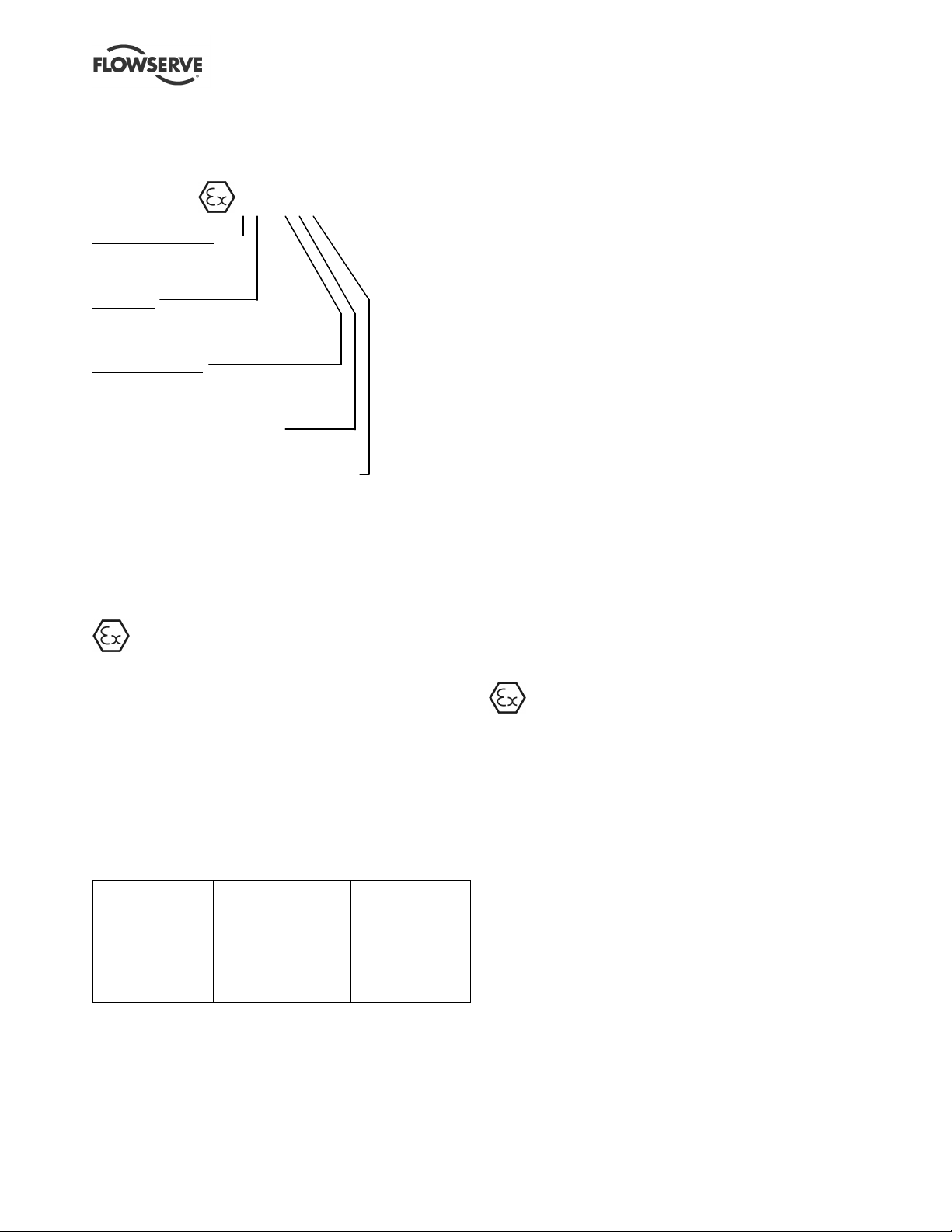
3.2 Name nomenclature
The pump size will be engraved on the nameplate
typically as below:
125X100-315
Nominal suction branch size in mm
Nominal discharge branch size in mm
Nominal maximum impeller diameter in mm
The typical nomenclature above is the general guide
to the Chemstar configuration description.
Page 9 of 44 flowserve.com
Page 10

CHEMSTAR USER INSTRUCTIONS ENGLISH 71569185 02-10
Identify the actual pump size and serial number from
the pump nameplate. Check that this agrees with the
applicable certification provided.
If it is a Chemstar pump with hydrodynamic sealing or
repeller then the pump size will be engraved on the
nameplate typically as below:
125X100M-315
M = repeller pump
3.3 Design of major parts
3.3.1 Pump casing
The pump casing is designed with a horizontal
centreline end inlet and a vertical centreline top outlet,
which makes it self venting. For ease of maintenance,
the pump is constructed so that pipe connections do not
have to be disturbed when internal maintenance is
required.
3.3.2 Impeller
An exclusive reverse vane impeller is fitted giving
important maintenance-reducing advantages. The
reverse vane impeller is set against the rear cover.
(On the hard-chrome iron material option the design
of the impeller is front open and is set against the
front of the casing.)
3.3.3 Shaft
The large diameter stiff shaft, mounted on bearings,
has a keyed drive end.
3.3.4 Bearing housing
The exclusive external micrometer shaft adjustment
bearing housing design enables quick and accurate
adjustment of impeller face clearance.
3.3.5 Pump bearings and lubrication
The pump is fitted with ball type bearings which may
be configured differently dependent on use. The
bearings may be oil or grease lubricated depending
upon the arrangement specified.
3.3.6 Rear cover
The rear cover has spigots between the pump casing
and bearing housing for optimum concentricity.
A fully confined gasket forms the seal between the
pump casing and the seal housing.
The rear cover designs provide improved performance
of mechanical seals. The design enables the optimum
sealing solution for each application to be fitted.
3.3.7 Shaft seal
The mechanical seal(s) attached to the pump shaft
seals the pumped liquid from the environment. Gland
packing may be fitted as an option.
3.3.8 Driver
The driver is normally an electric motor. Different drive
configurations may be fitted such as internal combustion
engines, turbines, hydraulic motors etc driving via
couplings, belts, gearboxes, drive shafts etc.
3.3.9 Accessories
Accessories may be fitted when specified by the
customer.
3.4 Performance and operating limits
This product has been selected to meet the
specifications of the purchase order. (See section 1.5.)
The following data is included as additional
information to help with your installation. It is typical,
and factors such as temperature, materials, and seal
type may influence this data. If required, a definitive
statement for your particular application can be
obtained from Flowserve.
3.4.1 Operating limits
Maximum ambient temperature
Maximum pump speed refer to the nameplate
- 20 to + 40 ºC
(- 4 to +104 ºF)
4 INSTALLATION
Equipment operated in hazardous locations
must comply with the relevant explosion protection
regulations. See section 1.6.4, Products used in
potentially explosive atmospheres.
4.1 Location
The pump should be located to allow room for access,
ventilation, maintenance and inspection with ample
headroom for lifting and should be as close as
practicable to the supply of liquid to be pumped. Refer
to the general arrangement drawing for the pump set.
4.2 Part assemblies
On baseplated pump sets the coupling elements are
supplied loose. It is the responsibility of the installer
to ensure that the pump set is finally lined up as
detailed in section 4.5.2, Alignment methods.
Page 10 of 44 flowserve.com
Page 11
CHEMSTAR USER INSTRUCTIONS ENGLISH 71569185 02-10
4.3 Foundation
There are many methods of installing
pump units to their foundations. The correct method
depends on the size of the pump unit, its location and
noise and vibration limitations. Non-compliance with
the provision of correct foundation and installation
may lead to failure of the pump and, as such, would
be outside the terms of the warranty.
Ensure the following are met:
a) The baseplate should be mounted onto a firm
foundation, either an appropriate thickness of
quality concrete or sturdy steel framework. (It
should NOT be distorted or pulled down onto the
surface of the foundation, but should be
supported to maintain the original alignment.)
b) Adjustable baseplates having stilt mount feet
have no foundation bolts securing it to the floor.
The feet are adjusted to maintain the top surface
of the baseplate level.
c) The pump and driver have been aligned before
dispatch within the permissible misalignment limits
defined in section 4.5.2, Alignment methods.
d) Where the baseplate does not have stilt mount
feet, install the baseplate onto packing pieces
evenly spaced and adjacent to foundation bolts.
Grouting provides solid contact between the pump
unit and foundation, prevents lateral movement of
running equipment and dampens resonant vibrations.
Foundation bolts should only be fully tightened when
the grout has cured.
4.5 Initial alignment
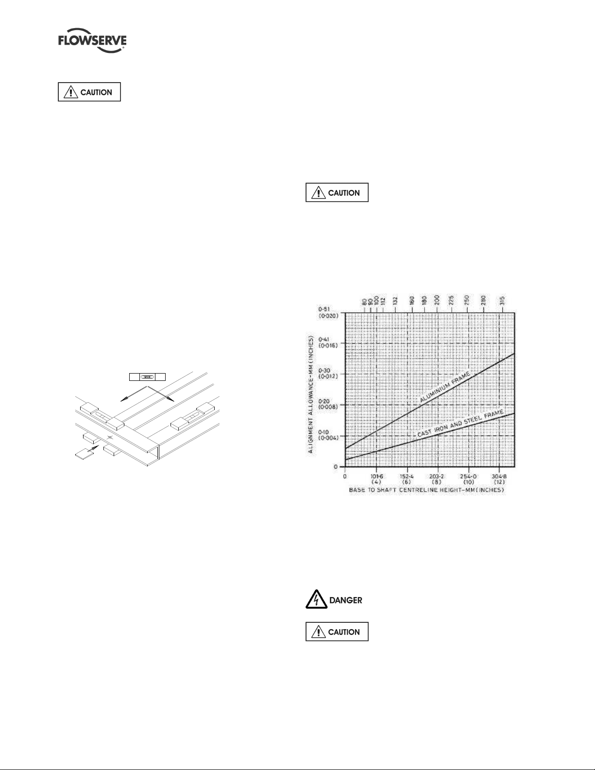
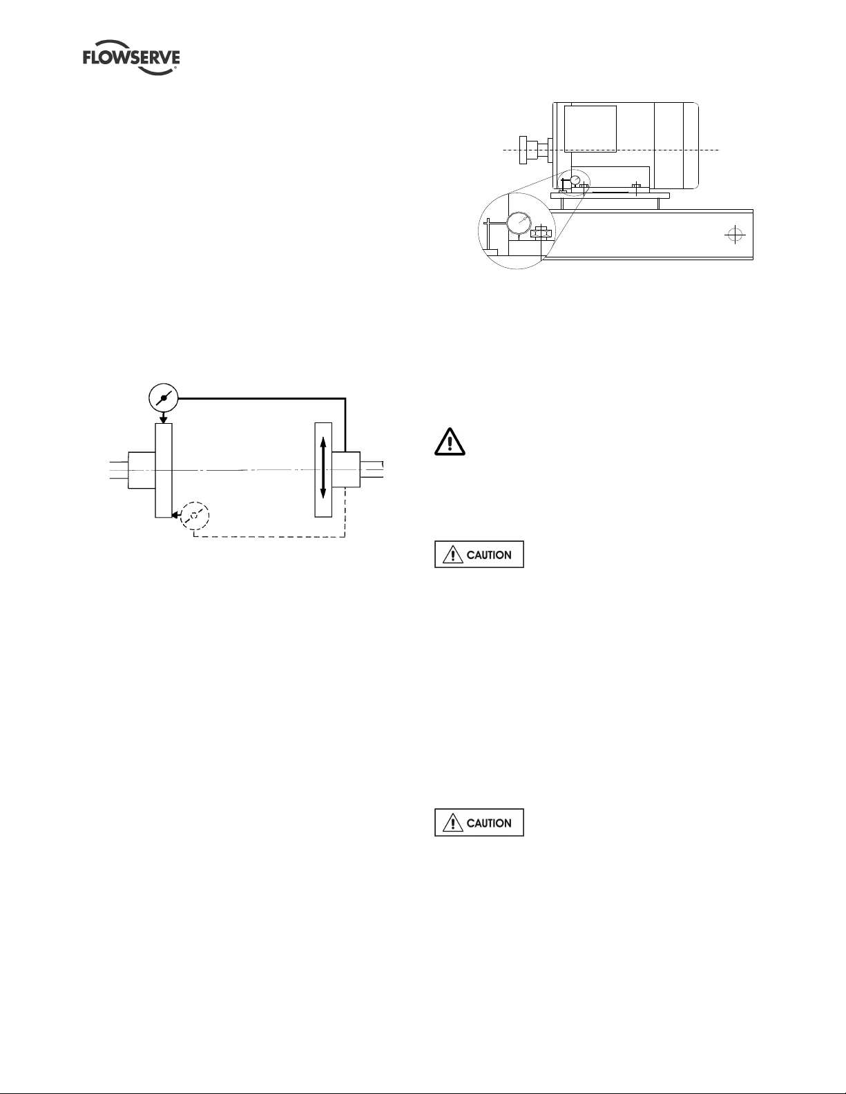
4.5.1 Thermal expansion
The pump and motor will normally
have to be aligned at ambient temperature with an
allowance for thermal expansion at operating
temperature. (See chart.) In pump installations
involving high liquid temperatures, the unit should be
run at the actual operating temperature, shut down
and the alignment checked immediately.
Motor and pump centre line height adjustment:
e) Level with shims between baseplate and packing
pieces.
f) Check alignment of pump and motor half
coupling. If this is not correct, it indicates that the
baseplate has become twisted and should be
corrected by re-shimming.
4.4 Grouting
Where applicable, grout in the foundation bolts.
After adding pipework connections and rechecking the
coupling alignment, the baseplate should then be
grouted in accordance with good engineering practice.
Fabricated steel and cast iron baseplates can be filled
with grout. Folded steel baseplates should be grouted
to locate their packing pieces. If in any doubt, please
contact your nearest service centre for advice.
Graph based on the assumptions that:
1. Operating temperature rise of the motor frame is 50 °C (90 °F).
2. Packing piece/motor stool is not affected.
Operation
1. Enter graph at base to shaft centre line height.
2. Read line for frame material.
3. Set motor shaft and coupling LOW by figure on left-hand side.
4.5.2 Alignment methods
Pump and driver must be isolated
electrically and the half couplings disconnected.
The alignment MUST be checked.
Page 11 of 44 flowserve.com
Page 12
CHEMSTAR USER INSTRUCTIONS ENGLISH 71569185 02-10
Angular
Although the pump will have been aligned at the factory
it is most likely that this alignment will have been
disturbed during transportation or handling. If
necessary, align the motor to the pump, not the pump to
the motor.
Alignment is achieved by adding or removing shims
under the motor feet and also moving the motor
horizontally as required. In some cases where the
alignment cannot be achieved it will be necessary to
move the pump before recommencing the above
procedure.
For couplings with narrow flanges use a dial indicator as
shown. Rotate both shafts together so that the dial
indicator probe keeps the same contact point onto the
flange during 360 degree rotation. The alignment
values are maximums for continuous service.
Parallel
Set a dial indicator as shown in sketch and loosen off
the holding down bolt while noting any deflection
reading on the dial test Indicator - a maximum of
0.05 mm (0.002 in.) is considered acceptable but any
more will have to be corrected by adding shims. For
example, if the dial test indicator shows the foot lifting
0.15 mm (0.006 in.) then this is the thickness of shim
to be placed under that foot. Tighten down and
repeat the same procedure on all other feet until all
are within tolerance
Permissible misalignment limits at working
temperature:
• Parallel alignment
- 0.25 mm (0.010 in.) TIR maximum
• Angular alignment
- 0.3 mm (0.012 in.) TIR maximum for couplings
not exceeding 100 mm (4 in.) flange diameter
- 0.5 mm (0.020 in.) TIR maximum for couplings
over 100 mm (4 in.) diameter
When checking parallel alignment, the total indicator
read-out (TIR) shown is twice the value of the actual
shaft displacement.
Align in the vertical plane first, then horizontally by
moving motor. Maximum pump reliability is obtained by
near perfect alignment of 0.05 - 0.075 mm (0.002 -
0.003 in.) parallel and 0.05 mm (0.002 in.) per 100 mm
(4 in.) of coupling flange diameter as angular
misalignment.
4.5.3 Check for soft foot
This is a check to ensure that there is no undue
stress on the driver holding down bolts; due to nonlevel baseplate or twisting. To check, remove all
shims and clean surfaces and tighten down driver to
the baseplate.
Complete piping as below and see section 4.7,
Final shaft alignment check up to and including section
5, Commissioning, startup, operation and shutdown,
before connecting driver and checking actual rotation.
4.6 Piping
Protective covers are fitted to the pipe
connections to prevent foreign bodies entering during
transportation and installation. Ensure that these
covers are removed from the pump before connecting
any pipes.
4.6.1 Suction and discharge pipework
In order to minimize friction losses and hydraulic
noise in the pipework it is good practice to choose
pipework that is one or two sizes larger than the
pump suction and discharge. Typically main
pipework velocities should not exceed 2 m/s (6 ft/sec)
suction and 3 m/s (9 ft/sec) on the discharge.
Take into account the available NPSH which must be
higher than the required NPSH of the pump.
Never use pump as a support for
piping.
Maximum forces and moments allowed on the pump
flanges vary with the pump size and type. To minimize
these forces and moments that may, if excessive, cause
misalignment, hot bearings, worn couplings, vibration
and the possible failure of the pump casing, the
following points should be strictly followed:
Page 12 of 44 flowserve.com
Page 13
CHEMSTAR USER INSTRUCTIONS ENGLISH 71569185 02-10
• Prevent excessive external pipe load
• Never draw piping into place by applying force to
pump flange connections
• Do not mount expansion joints so that their force,
due to internal pressure, acts on the pump flange
Ensure piping and fittings are flushed
before use.
Ensure piping for hazardous liquids is arranged
to allow pump flushing before removal of the pump.
4.6.2 Suction piping
a) The inlet pipe should be one or two sizes larger
than the pump inlet bore and pipe bends should
be as large a radius as possible.
b) On suction lift the piping should be inclined up
towards the pump inlet with eccentric reducers
incorporated to prevent air locks.
c) On positive suction, the inlet piping must have a
constant fall towards the pump.
d) The pipe next to the pump should be the same
diameter as the pump suction and have a minimum
of two pipe diameters of straight section between
the elbow and the pump inlet flange. Where the
NPSH margin is not large, it is recommended that
the straight pipe is 5 to 10 times the pipe diameter.
(See section 10.3, Reference 1.) Inlet strainers,
when used, should have a net 'free area' of at least
three times the inlet pipe area.
e) Fitting isolation and non-return valves will allow
easier maintenance.
f) Never throttle pump on suction side and never
place a valve directly on the pump inlet nozzle.
4.6.3 Discharge piping
A non-return valve should be located in the discharge
pipework to protect the pump from excessive back
pressure and hence reverse rotation when the unit is
stopped.
Fitting an isolation valve will allow easier maintenance.
4.6.4 Auxiliary piping
c) Always stagger the end gaps of the packing by
90 degrees apart to ensure the best seal.
d) To speed installation of each ring, have an
assistant turn the pump shaft in the correct
direction. This movement will tend to draw the
rings into the stuffing box.
e) Lightly tighten the gland.
f) Final adjustments are covered in section 5.8,
Running the pump.
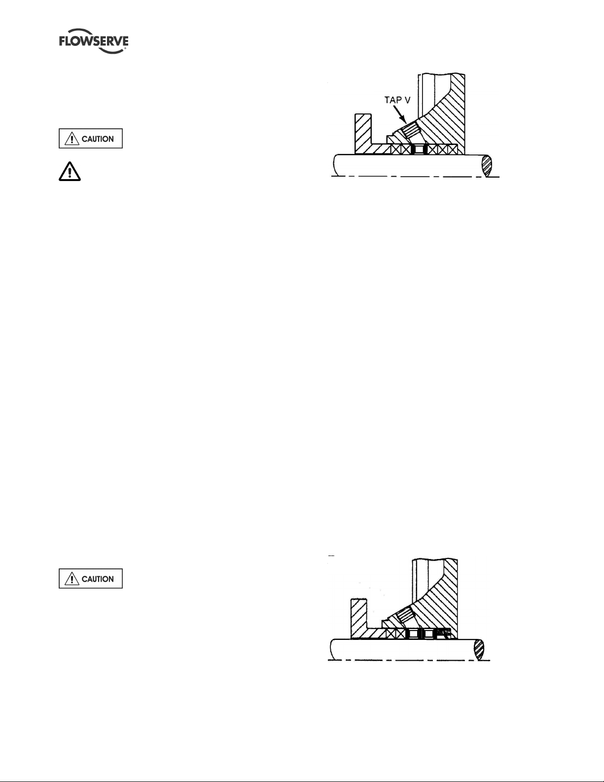
g) When suction pressure is below ambient
pressure and stuffing box head over total suction
head is less than 10 m (33 ft), it may be
necessary to feed gland packing with compatible
liquid to the pumpage to provide lubrication and
prevent the ingress of air. This is to be added
through tap V shown above. The pressure of the
feed liquid should be at least 1 bar (14.5 psi)
above the stuffing box pressure, regulated to a
flow rate of 0.25 to 0.5 m3/h (1 to 2 USgpm). At
lower speeds, grease lubrication may be used
when compatible with the pumpage. In non-
abrasive applications, where the pumpage itself
is sufficient to lubricate the packing without an
external pipeline, tap V should be plugged.
h) When a special abrasive liquid packing
arrangement is specified, the installation
procedures are the same as the standard packing
with the following exceptions. The special lip seal
is installed first, followed by two seal cage
assemblies, then two of the packing rings provided
as shown below. An external compatible liquid
source line should be connected to tap V, in the top
of the stuffing box.
The connections that are to be piped
up will have been fitted with protective metal or
plastic plugs which will need to be removed.
4.6.4.1 Pumps fitted with packed glands
a) Packing is to be fitted before use.
b) A temporary PTFE lip seal may have been
installed against the face of the stuffing box for
shipping. If so, discard this lip seal and slide the
packing rings [4130] and lantern ring [4134] into
the stuffing box in the order shown.
Page 13 of 44 flowserve.com
Page 14
CHEMSTAR USER INSTRUCTIONS ENGLISH 71569185 02-10
Chemstar repeller pump only
In Chemstar pumps fitted with a repeller and with
dry running gland packing as secondary sealing
the packing is factory installed.
In some applications to limit the gland packing
fouling, Chemstar repeller pumps could possibly
have a 0.25 to 0.5 m³/h external clean compatible
liquid flush injected into the stuffing box at 5 to 10 m
head above ambient pressure prior to start up and
prior to shut down.
4.6.4.2 Pumps fitted with mechanical seals
The Seal Sentry design of the anti-vortex single
internal rear cover provides excellent liquid circulation
around the seal and will not normally require a
separate flush.
Single seals requiring flush by re-circulation of pumped
liquid will normally be provided with the auxiliary piping
from pump casing already fitted. (Where an external
compatible flush is specified, the piping to the pump is
the responsibility of the pump installer.)
Rear covers with an auxiliary quench connection
require connection to a suitable source of liquid, low
pressure steam or static pressure from a header tank.
Recommended pressure is 0.35 bar (5 psi) or less.
Double seals require a barrier liquid between the
seals, compatible with the pumped liquid.
With back-to-back double seals, the barrier liquid should
be at a minimum pressure of 1 bar (15 psi) above the
maximum pressure on the pump side of the inner seal
and at least 1 bar (15 psi) above ambient external
pressure. The barrier liquid pressure must not exceed
limitations of the seal on the atmospheric side.
For toxic service the barrier liquid supply and
discharge must be handled safely and in line with
local legislation.
Seal chamber pressure:
Mechanical
seal
Gland
packing
Use seal manufacturer's limits or ask seal
manufacturer to verify seal pressure
Maximum stuffing box pressure =
5 bar (3 500 r/min), 7 bar (2 900 r/min)
and 10 bar (1 450 and 1 750 r/min)
Special seals may require different auxiliary piping to
that described above. Consult separate User
Instructions and/or Flowserve if unsure of correct
method or arrangement.
For pumping hot liquids, to avoid seal damage, it is
recommended that any external flush/cooling supply
be continued after stopping the pump.
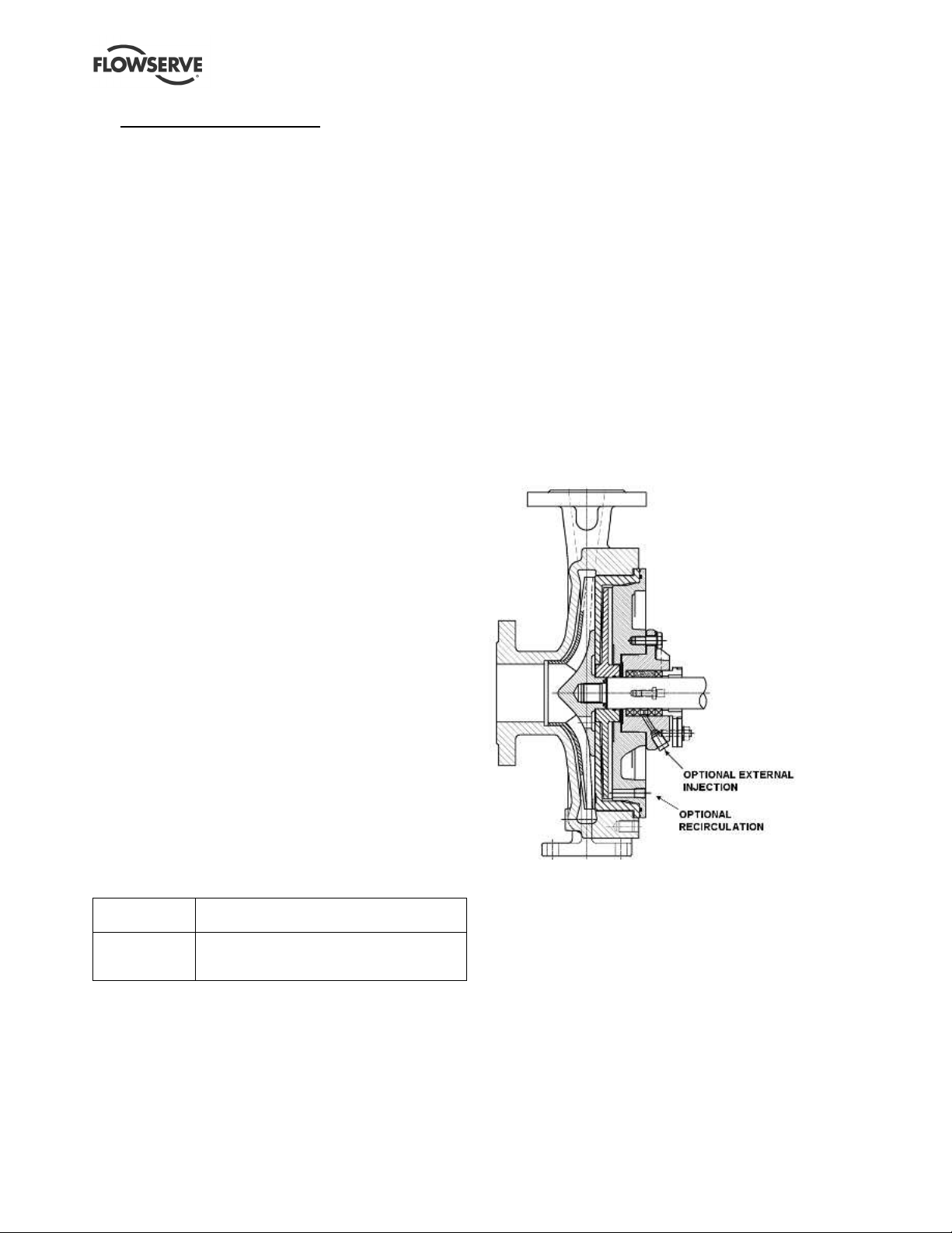
4.6.4.3 External recirculation and flush for
pumps fitted with repeller
Only dry running single mechanical seals or packing
arrangement approved by Flowserve must be used.
(Refer to section 8.3.) In some applications, to keep
seal faces clean, pumps could possibly have a 0.25
to 0.5 m3/h external clean compatible liquid flush
injected into the seal cavity at 5 to 10 m head above
atmospheric pressure prior to start up and prior to
shut down. The Chemstar repeller chamber can
have an auxiliary recirculation connection back to the
suction side pipe.
Customers should always seek instructions from
Flowserve if the pump is not supplied with the
optional recirculation line or external flush and if it is
planned to install these later.
4.6.4.4 Pumps fitted with heating/cooling jackets
Connect the heating/cooling pipes from the site
supply. The top connection should be used as the
outlet to ensure complete filling/venting of the jacket
unless the heating medium is steam, when the
bottom connection should be used as the outlet.
4.6.5 Final checks
Check the tightness of all bolts in the suction and
discharge pipework. Check also the tightness of all
foundation bolts.
Page 14 of 44 flowserve.com
Page 15

CHEMSTAR USER INSTRUCTIONS ENGLISH 71569185 02-10
4.7 Final shaft alignment check
After connecting piping to the pump, rotate the shaft
several times by hand to ensure there is no binding
and all parts are free.
Recheck the coupling alignment, as previously
described, to ensure no pipe strain. If pipe strain
exists, correct piping.
4.8 Electrical connections
Electrical connections must be made
by a qualified Electrician in accordance with relevant
local national and international regulations.
It is important to be aware of the EUROPEAN
DIRECTIVE on potentially explosive areas where
compliance with IEC60079-14 is an additional
requirement for making electrical connections.
It is important to be aware of the EUROPEAN
DIRECTIVE on electromagnetic compatibility when
wiring up and installing equipment on site. Attention
must be paid to ensure that the techniques used during
wiring/installation do not increase electromagnetic
emissions or decrease the electromagnetic immunity of
the equipment, wiring or any connected devices. If in
any doubt contact Flowserve for advice.
The motor must be wired up in
accordance with the motor manufacturer's
instructions (normally supplied within the terminal
box) including any temperature, earth leakage,
current and other protective devices as appropriate.
The identification nameplate should be checked to
ensure the power supply is appropriate.
A device to provide emergency stopping must
be fitted.
If not supplied pre-wired to the pump unit, the
controller/starter electrical details will also be supplied
within the controller/starter.
For electrical details on pump sets with controllers
see the separate wiring diagram.
See section 5.4, Direction of rotation
before connecting the motor to the electrical supply.
4.9 Protection systems
The following protection systems are
recommended particularly if the pump is installed in a
potentially explosive area or is handling a hazardous
liquid. If in any doubt consult Flowserve.
If there is any possibility of the system allowing the
pump to run against a closed valve or below
minimum continuous safe flow a protection device
should be installed to ensure the temperature of the
liquid does not rise to an unsafe level.
If there are any circumstances in which the system
can allow the pump to run dry, or start up empty, a
power monitor should be fitted to stop the pump or
prevent it from being started. This is particularly
relevant if the pump is handling a flammable liquid.
If leakage of product from the pump or its associated
sealing system can cause a hazard it is recommended
that an appropriate leakage detection system is
installed.
To prevent excessive surface temperatures at
bearings it is recommended that temperature or
vibration monitoring are carried out.
5 COMMISSIONING, START-UP,
OPERATION AND SHUTDOWN
These operations must be carried
out by fully qualified personnel.
5.1 Pre-commissioning procedure
5.1.1 Lubrication
Determine the mode of lubrication of the pump set,
eg grease, oil, product lubrication etc.
For oil lubricated pumps, fill the bearing
housing with correct grade of oil to the correct level, ie
sight glass or constant level oiler bottle. The oil level
required is half way up in the sight glass. For
approximate oil quantity refer to section 5.2.2,
Bearing sizes and capacities.
When fitted with a constant level oiler, the bearing
housing should be filled by unscrewing or hinging back
the transparent bottle and filling the bottle with oil. The oil
filled bottle should then be refitted so as to return it to the
upright position. Filling of the bottle should be repeated
until oil remains visible within the bottle. Oil must be
visible in the oiler bottle at all times of operation.
Where an adjustable body oiler is fitted this should be
set to the height shown in the figure below or in the
lowest position in the case of the Trico oiler.
Page 15 of 44 flowserve.com
Page 16

CHEMSTAR USER INSTRUCTIONS ENGLISH 71569185 02-10
Frame
Grease lubricated pumps and electric motors are
supplied pre-greased. To regrease, remove the pipe
plug from both the inboard and outboard bearing
location. Apply grease through the grease nipples until
it comes out of the vent holes then reinstall the pipe
plugs. Do not over grease. Grease lubricated sealed
bearings do not require relubrication and should be
replaced on a regular maintenance scheme.
When fitted with a sight glass, fill the bearing housing
with oil by unscrewing the oil filler/breather and fill
through the hole.
Other drivers and gearboxes, if appropriate, should
be lubricated in accordance with their manuals.
5.2 Pump lubricants
5.2.1 Recommended oil lubricants
Oil Splash / force feed / purge oil mist lubrication
Viscosity cSt
@ 40 ºC
Oil temperature range *
lubrication
Centrifugal pump
Oil companies and
* Note that it normally takes 2 hours for bearing temperature to stabilize and the final temperature will depend on the ambient, r/min, pumpage
temperature and pump size. Also some oils have a greater viscosity index than the minimum acceptable of 95 (eg Mobil DTE13M) which may
extend the minimum temperature capability of the oil. Always check the grade capability where the ambient is less than -5 ºC (23 ºF).
†
Use LSC for oil mist. Oil parameters provide flash point >166 ºC (331 ºF), density >0.87 @ 15 ºC (59 ºF), pour point of -10 ºC (14 ºF) or lower.
Designation to ISO 3448
and DIN51524 part 2
BP Castrol †
ESSO †
ELF/Total †
LSC (for oil mist)
ExxonMobil †
lubricants
Wintershall (BASF Group) †
Q8 †
Shell †
Chevron Texaco †
Fuchs †
Energol HLP-HM 32 Energol HLP-HM 46 Energol HLP-HM 68
LSO 32 (Synthetic oil) LSO 46 (Synthetic oil) LSO 68 (Synthetic oil)
5.2.2 Bearing sizes and capacities
Medium duty
oil bearings
size
Inboard end Outboard end Inboard end Outboard end Inboard end Outboard end Outboard end
Ball
bearing
A
6307 C3
B
6309 C3
C
6311 C3
D
6315 C3
Note: The bearing sizes do not constitute a purchasing specification.
'A' in the double row angular contact bearing nomenclature defines the requirement of no filling slot.
Duplex back-to-back bearings at drive end may be required depending upon operating conditions and pump model.
Double row
angular contact
3307 A C3
3309 A C3
3311 A C3
3314 A C3
Ball
bearing
6307 C3 Z
6309 C3 Z
6311 C3 Z
6315 C3 Z
32 46 68
-5 to 65 ºC
(23 to 149 ºF)
ISO VG 32
32 HLP
NUTO HP 32 NUTO HP 46 NUTO HP 68
ELFOLNA DS 32
Azolla ZS 32
Mobil DTE 24 Mobil DTE 25 Mobil DTE 26
Q8 Haydn 32 Q8 Haydn 46 Q8 Haydn 68
Shell Tellus 32 Shell Tellus 46 Shell Tellus 68
Rando HD 32 Rando HD 46 Rando HD 68
Wiolan HS32 Wiolan HS46 Wiolan HS68
Renolin CL 32 Renolin CL 46 Renolin CL 68
Regreasable
bearings
Double row
angular contact
3307 A C3 Z
3309 A C3 Z
3311 A C3 Z
3314 A C3 Z
metallic shields
-5 to 78 ºC
(23 to 172 ºF)
ISO VG 46
46 HLP
ELFOLNA DS 46
Azolla ZS 46
Sealed grease
bearings
Ball bearing
6307 C3 2Z
6309 C3 2Z
6311 C3 2Z
6515 C3 2Z
Double row
angular contact
3307A C3 2Z
3309A C3 2Z
3311A C3 2Z
3314A C3 2Z
-5 to 80 ºC
(23 to 176 ºF)
ISO VG 68
68 HLP
ELFOLNA DS 68
Azolla ZS 68
Optional oil
bearings
Duplex back-
to-back AC
7307
7309
7311
7314
Approx
oil
capacity
litre
(fl.oz)
0.25 (8.5)
0.5 (16.9)
0.6 (20.3)
1.8 (60.9)
Page 16 of 44 flowserve.com
Page 17

CHEMSTAR USER INSTRUCTIONS ENGLISH 71569185 02-10
5.2.3 Recommended grease lubricants
Grease NLGI 2 * NLGI 3
Temp. range
Designation
acc. to DIN
BP
Elf
Fuchs
ESSO
Mobil
Q8
Shell
Texaco
SKF
* NLGI 2 is an alternative grease and is not to be mixed with other
grades.
** Standard pre-packed grease for fitted antifriction bearings.
-20 to +100 ºC
(-4 to +212 ºF)
KP2K-25 KP3K-20
Energrease LS-EP2 Energrease LS-EP3
Multis EP2 Multis EP3
RENOLIT EP2 RENOLIT EP3
Beacon EP2 Beacon EP3
Mobilux EP2 Mobilux EP3 **
Rembrandt EP2 Rembrandt EP3
Alvania EP2 Alvania EP2
Multifak EP2 Multifak EP3
LGEP 2 -
-20 to +100 ºC
(-4 to +212 ºF)
5.2.4 Recommended fill quantities
Refer to section 5.2.2, Bearing sizes and capacities.
5.2.5 Lubrication schedule
5.2.5.1 Oil lubricated bearings
Normal oil change intervals are 4 000 operating hours
or at least every 6 months. For pumps on hot service
or in severely damp or corrosive atmospheres, the oil
will require changing more frequently. Lubricant and
bearing temperature analysis can be useful in
optimizing lubricant change intervals.
The lubricating oil should be a high quality oil having
oxidisation and foam inhibitors, or synthetic oil. Do
not use detergent oil.
The bearing temperature may be allowed to rise to
50 ºC (90 ºF) above ambient, but should not exceed
82 ºC (180 ºF) (API 610 limit). A continuously rising
temperature, or an abrupt rise, indicates a fault.
When oil mist lubrication is specified the bearing
housings are furnished with a single top inlet tap, a
vent hole at the outboard bearing and a bottom drain.
Pumps which handle high temperature liquids may
require their bearings to be cooled to prevent bearing
temperatures exceeding their limits. Oil cooling with
regular ambient conditions is normally required for
pumpage above 175 ºC (350 ºF) and up to 260 ºC
(500 ºF). Temperature applications above 260 ºC
(500 ºF) are normally not possible. Consult Flowserve
if unsure of correct method or arrangement.
5.2.5.2 Grease lubricated bearings
When grease nipples are fitted, one charge between
grease changes is advisable for most operating
conditions; ie 2 000 hours interval. Normal intervals
between grease changes are 4 000 hours or at least
every 6 months.
The characteristics of the installation and severity of
service will determine the frequency of lubrication.
Lubricant and bearing temperature analysis can be
useful in optimizing lubricant change intervals.
Sealed bearings are optional. These bearings are
packed by the bearing manufacturer and should not
be relubricated. These should be replaced on a
regular maintenance schedule.
The bearing temperature may be allowed to rise to
95 ºC (203 ºF) maximum during the running-in period.
This should be followed by a steady fall in
temperature to around 50 ºC (90 ºF) above ambient
after 1.5 to 2 hours of operation as the grease soap
settles. A continuously rising temperature, or an
abrupt rise, indicates a fault.
For most operating conditions, a quality grease
having a lithium soap base and NLGI consistency of
No 2 or No 3 is recommended. The drop point
should exceed 175 ºC (350 ºF).
Never mix greases containing different
bases, thickeners or additives.
5.3 Impeller clearance
Impeller clearance was set at the factory based on the
temperature given in the customer datasheet at the time
the pump was purchased. For setting instructions, see
section 6.7, Setting impeller clearance.
5.4 Direction of rotation
Serious damage can result if the
pump is started or run in the wrong direction of
rotation. These pumps turn clockwise as viewed from
the motor end.
The pump is shipped with the coupling
element removed. Ensure the direction of rotation of
the motor is correct before fitting the coupling element.
Direction of rotation must correspond to the direction
arrow.
If maintenance work has been carried
out to the site's electricity supply, the direction of
rotation should be re-checked as above in case the
supply phasing has been altered.
Page 17 of 44 flowserve.com
Page 18

CHEMSTAR USER INSTRUCTIONS ENGLISH 71569185 02-10
5.5 Guarding
Guarding is supplied fitted to the pump set.
In member countries of the EU and EFTA, it is a legal
requirement that fasteners for guards must remain
captive in the guard to comply with the Machinery
Directive 2006/42/EC. When releasing such guards,
the fasteners must be unscrewed in an appropriate
way to ensure that the fasteners remain captive.
Whenever guarding is removed or disturbed ensure
that all the protective guards are securely refitted
prior to start-up.
5.6 Priming and auxiliary supplies
5.6.1 Filling and priming
Ensure inlet pipe and pump casing is
completely full of liquid before starting continuous
duty operation.
Priming may be carried out with an ejector, vacuum
pump interceptor or other equipment, or by flooding
from the inlet source.
When in service, pumps using inlet pipes with foot
valves may be primed by passing liquid back from the
outlet pipe through the pump.
5.6.2 Auxiliary supplies
Ensure all electrical, hydraulic,
pneumatic, sealant and lubrication systems (as
applicable) are connected and operational.
5.7 Starting the pump
a) Ensure flushing and/or cooling/
heating liquid supplies are turned ON, before
starting pump.
b) CLOSE the outlet valve.
c) OPEN all inlet valves.
d) Prime the pump.
e) Start motor and check the outlet pressure.
f) If the pressure is satisfactory, SLOWLY open the
outlet valve.
g) Do not run the pump against a
closed valve for more than 30 seconds.
h) If NO pressure, or LOW pressure, STOP the
pump. Refer to section 7, Faults; causes and
remedies for fault diagnosis.
5.8 Running the pump
5.8.1 Pumps fitted with packed gland
If the pump has a packed gland there must be some
leakage from the gland. Gland nuts should initially be
finger-tight only. Leakage should take place soon
after the stuffing box is pressurised.
The gland must be adjusted evenly to give
visible leakage and concentric alignment of the gland
ring to avoid excess temperature. If no leakage takes
place the packing will begin to overheat. If
overheating takes place the pump should be stopped
and allowed to cool before being re-started. When
the pump is re-started, check to ensure leakage is
taking place at the packed gland [4130].
If hot liquids are being pumped it may be necessary to
slacken the gland nuts to achieve leakage.
The pump should be run for 10 minutes with steady
leakage and the gland nuts tightened by 10 degrees at a
time until leakage is reduced to an acceptable level,
normally 30 to 120 drops per minute. Bedding in of the
packing may take another 15 minutes.
If the pump is equipped with a quench type packing
gland follow the same adjustment procedure as
above after closing the quench line valve. Re-open
the quench line valve after adjusting the packing to
an acceptable leakage rate.
If a grease lubricator is used for packing lubrication,
give the lubricator handle one or two turns every 100
hours of operation.
Care must be taken when adjusting the gland
on an operating pump. Safety gloves are essential.
Loose clothing must not be worn to avoid being
caught up by the pump shaft. Shaft guards must be
replaced after the gland adjustment is complete.
Never run gland packing dry, even for
a short time.
5.8.2 Pumps fitted with mechanical seal
Mechanical seals require no adjustment. Any slight
initial leakage will stop when the seal is run in. Seals
will always have leakage emission from the boundary
film edge in operation.
Before pumping dirty liquids it is advisable, if
possible, to run the pump in using clean liquid to
safeguard the seal face.
Page 18 of 44 flowserve.com
Page 19

CHEMSTAR USER INSTRUCTIONS ENGLISH 71569185 02-10
External flush or quench should be
started before the pump is run and allowed to flow for
a period after the pump has stopped.
Never run a mechanical seal dry,
even for a short time.
5.8.3 Pumps fitted with repeller and gland
packing
Before starting the pump, flood the suction, ensure
that the shaft can rotate freely and that the gland
leaks to an acceptable level of 30 to 120 drops per
minute.
If not, adjust the gland follower nut [6580.3] to make
sure that the gland packing [4130.1] is wetted either
by pumped liquid or by externally flushed clean liquid.
Leakage will stop completely as soon as the pump is
started and the hydrodynamic sealing takes place.
5.8.4 Bearings
If the pumps are working in a potentially
explosive atmosphere temperature or vibration
monitoring at the bearings is recommended.
If bearing temperatures are to be monitored it is
essential that a benchmark temperature is recorded
at the commissioning stage and after the bearing
temperature has stabilized.
• Record the bearing temperature (t) and the
ambient temperature (ta)
• Estimate the likely maximum ambient
temperature (tb)
• Set the alarm at (t+tb-ta+5) ºC (t+tb-ta+10) ºF
and the trip at 100 ºC (212 ºF) for oil lubrication
and 105 ºC (220 ºF) for grease lubrication
It is important, particularly with grease lubrication, to
keep a check on bearing temperatures. After start up
the temperature rise should be gradual, reaching a
maximum after approximately 1.5 to 2 hours. This
temperature should then remain constant or
marginally reduce with time. Refer to section 5.2.5
for further information.
5.8.5 Normal vibration levels, alarm and trip
For guidance, pumps generally fall under a classification
for rigid support machines within the International
rotating machinery standards and the recommended
maximum levels below are based on those standards.
Alarm and trip values for installed
pumps should be based on the actual measurements
(N) taken on the pump in the fully commissioned as
new condition. Measuring vibration at regular
intervals will then show any deterioration in pump or
system operating conditions.
Vibration velocity –
unfiltered
Normal N
Alarm N x 1.25
Shutdown trip N x 2.0
Horizontal pumps
≤≤≤≤ 15 kW mm/sec
(in./sec) r.m.s.
≤ 3.0 (0.12) ≤ 4.5 (0.18)
≤ 3.8 (0.15) ≤ 5.6 (0.22)
≤ 6.0 (0.24) ≤ 9.0 (0.35)
> 15 kW
mm/sec (in./sec)
r.m.s.
Where a grease lubricated unit is utilised in a vertical
shaft configuration with a duck-foot bend onto the
pump suction, the following apply:
Vibration velocity
– unfiltered
Normal N
Alarm N x 1.25
Shutdown trip N x 2.0
Vertical configurations
mm/sec (in./sec) r.m.s.
≤ 7.1 (0.28)
≤ 9.0 (0.35)
≤ 14.2 (0.56)
5.8.6 Stop/start frequency
Pump sets are normally suitable for the number of
equally spaced stop/starts per hour shown in the
table below. Check capability of the driver and
control/starting system before commissioning.
Motor rating kW (hp)
Up to 15 (20) 15
Between 15 (20) and 90 (120) 10
Above 90 (120) 6
Maximum stop/starts
per hour
Where duty and standby pumps are installed it is
recommended that they are run alternately every
week.
5.9 Stopping and shutdown (all series)
a) Close the outlet valve, but ensure
that the pump runs in this condition for no more
than a few seconds.
b) Stop the pump.
c) Switch off flushing and/or cooling/heating liquid
supplies at a time appropriate to the process.
d) For prolonged shut-downs and
especially when ambient temperatures are likely
to drop below freezing point, the pump and any
cooling and flushing arrangements must be
drained or otherwise protected.
Page 19 of 44 flowserve.com
Page 20

CHEMSTAR USER INSTRUCTIONS ENGLISH 71569185 02-10
e) For some applications, it may be recommended to
provide an external compatible clean liquid injection
into the seal cavity for some time before each pump
switch off. If it is a repeller type pump, clean liquid
may need to be flushed into the repeller chamber for
some time before each pump stop.
5.10 Hydraulic, mechanical and electrical
duty
This product has been supplied to meet the performance
specifications of your purchase order, however it is
understood that during the life of the product these may
change. The following notes may help the user decide
how to evaluate the implications of any change. If in
doubt contact your nearest Flowserve office.
5.10.1 Specific gravity (SG)
Pump capacity and total head in metres (feet) do not
change with SG, however pressure displayed on a
pressure gauge is directly proportional to SG. Power
absorbed is also directly proportional to SG. It is
therefore important to check that any change in SG
will not overload the pump driver or over-pressurize
the pump.
5.10.2 Viscosity
For a given flow rate the total head reduces with
increased viscosity and increases with reduced
viscosity. Also for a given flow rate the power
absorbed increases with increased viscosity, and
reduces with reduced viscosity. It is important that
checks are made with your nearest Flowserve office if
changes in viscosity are planned.
5.10.3 Pump speed
Changing pump speed effects flow, total head, power
absorbed, NPSHR, noise and vibration. Flow varies in
direct proportion to pump speed, head varies as speed
ratio squared and power varies as speed ratio cubed.
The new duty, however, will also be dependent on the
system curve. If increasing the speed, it is important
therefore to ensure the maximum pump working
pressure is not exceeded, the driver is not overloaded,
NPSHA > NPSHR, and that noise and vibration are
within local requirements and regulations.
A Chemstar repeller pump must be run at
the speed agreed in the contract. This speed is
relative to the allowable speed range for which the
pump has been designed. Please seek advice from
your nearest Flowserve office first, if you consider
driving the pump at a speed deviating from these
requirements.
5.10.4 Net positive suction head (NPSHA)
NPSH available (NPSHA) is a measure of the head
available in the pumped liquid, above its vapour
pressure, at the pump suction branch.
NPSH required (NPSHR) is a measure of the head
required in the pumped liquid, above its vapour
pressure, to prevent the pump from cavitating. It is
important that NPSHA > NPSHR. The margin between
NPSHA > NPSHR should be as large as possible.
Chemstar repeller pumps are designed for
the particular suction head values that have been
agreed in the contract. For any changes in the
suction head please consult your nearest Flowserve
office for advice.
If any change in NPSHA is proposed, ensure these
margins are not significantly eroded. Refer to the
pump performance curve to determine exact
requirements particularly if flow has changed.
If in doubt please consult your nearest Flowserve
office for advice and details of the minimum allowable
margin for your application.
5.10.5 Pumped flow
Flow must not fall outside the minimum and
maximum continuous safe flow shown on the pump
performance curve and or data sheet.
For Chemstar repeller pumps only.
Please consult your nearest Flowserve office for advice
if you intend to use the pump set at a flow rate outside
the flow rate range for which it was sold.
6 MAINTENANCE
6.1 General
It is the plant operator's responsibility to ensure
that all maintenance, inspection and assembly work
is carried out by authorized and qualified personnel
who have adequately familiarized themselves with
the subject matter by studying this manual in detail.
(See also section 1.6.)
Any work on the machine must be performed when it
is at a standstill. It is imperative that the procedure
for shutting down the machine is followed, as
described in section 5.9.
Guard fasteners must remain captive during
dismantling of guards, as described in section 5.5.
Page 20 of 44 flowserve.com
Page 21

CHEMSTAR USER INSTRUCTIONS ENGLISH 71569185 02-10
On completion of work all guards and safety devices
must be re-installed and made operative again.
Before restarting the machine, the relevant
instructions listed in section 5, Commissioning, start
up, operation and shut down must be observed.
Oil and grease leaks may make the ground
slippery. Machine maintenance must always
begin and finish by cleaning the ground and the
exterior of the machine.
If platforms, stairs and guard rails are required for
maintenance, they must be placed for easy access to
areas where maintenance and inspection are to be
carried out. The positioning of these accessories
must not limit access or hinder the lifting of the part to
be serviced.
When air or compressed inert gas is used in the
maintenance process, the operator and anyone in the
vicinity must be careful and have the appropriate
protection.
Do not spray air or compressed inert gas on skin.
Do not direct an air or gas jet towards other people.
Never use air or compressed inert gas to clean
clothes.
Before working on the pump, take measures to
prevent an uncontrolled start. Put a warning board
on the starting device with the words:
"Machine under repair: do not start".
With electric drive equipment, lock the main switch
open and withdraw any fuses. Put a warning board
on the fuse box or main switch with the words:
"Machine under repair: do not connect".
Never clean equipment with inflammable solvents or
carbon tetrachloride. Protect yourself against toxic
fumes when using cleaning agents.
6.2 Maintenance schedule
It is recommended that a maintenance plan and
schedule is adopted, in line with these User
Instructions, to include the following:
a) Any auxiliary systems installed must be monitored,
if necessary, to ensure they function correctly.
b) Gland packings must be adjusted correctly to
give visible leakage and concentric alignment of
the gland follower to prevent excessive
temperature of the packing or follower.
c) Check for any leaks from gaskets and seals.
The correct functioning of the shaft seal must be
checked regularly.
d) Check bearing lubricant level, and if the hours
run show a lubricant change is required.
e) Check that the duty condition is in the safe
operating range for the pump.
f) Check vibration, noise level and surface temperature
at the bearings to confirm satisfactory operation.
g) Check dirt and dust is removed from areas around
close clearances, bearing housings and motors.
h) Check coupling alignment and re-align if necessary.
Our specialist service personnel can help with
preventative maintenance records and provide
condition monitoring for temperature and vibration to
identify the onset of potential problems.
If any problems are found the following sequence of
actions should take place:
a) Refer to section 7, Faults; causes and remedies,
for fault diagnosis.
b) Ensure equipment complies with the
recommendations in this manual.
c) Contact Flowserve if the problem persists.
6.2.1 Routine inspection (daily/weekly)
The following checks should be made
and the appropriate action taken to remedy any
deviations:
a) Check operating behaviour. Ensure noise,
vibration and bearing temperatures are normal.
b) Check that there are no abnormal fluid or
lubricant leaks (static and dynamic seals) and
that any sealant systems (if fitted) are full and
operating normally.
c) Check that shaft seal leaks are within acceptable
limits.
d) Check the level and condition of oil lubricant. On
grease lubricated pumps, check running hours
since last recharge of grease or complete grease
change.
e) Check any auxiliary supplies eg heating/cooling
(if fitted) are functioning correctly.
Refer to the manuals of any associated
equipment for routine checks needed.
6.2.2 Periodic inspection (six monthly)
a) Check foundation bolts for
security of attachment and corrosion.
b) Check pump running records for hourly usage to
determine if bearing lubricant requires changing.
Page 21 of 44 flowserve.com
Page 22

CHEMSTAR USER INSTRUCTIONS ENGLISH 71569185 02-10
c) The coupling should be checked for correct
alignment and worn driving elements.
Refer to the manuals of any associated
equipment for periodic checks needed.
6.2.3 Re-lubrication
For general guidelines refer to section 5.2.5,
Lubrication schedule.
Lubricant and bearing temperature analysis can be
useful in optimizing lubricant change intervals.
6.2.4 Mechanical seals
When leakage becomes unacceptable the seal will
need replacement.
6.2.5 Gland packing
The stuffing box split gland can be completely removed
for re-packing or to enable the addition of extra rings of
packing. The stuffing box is normally supplied with a
lantern ring to enable a clean or pressurised flush to the
centre of the packing. If not required, this can be
replaced by an extra 2 rings of packing.
6.2.6 Repeller pump with gland packing
When the pump is stopped there could be leakage
exceeding the acceptable rate. This is due to the
setting of the gland packing and the narrow leak path
created at the shaft to soft packing interface. The
instructions in section 5.8.3 must be followed during
restarting of the pump.
If the pumped liquid can solidify in the repeller
chamber, an external clean liquid injection shall be
provided into the chamber before restarting the
pump. (Refer to optional recirculation in section
4.6.4.3.)
It is possible to flush the packing when the packing
arrangement includes one or more lantern rings.
If the clearance between the shaft and packing is too
large then the packing must be replaced. Special
packing arrangements and assembly processes are
explained in section 6.10.6.
Chemstar repeller pumps fitted with two packing rings
and injectable packing cannot be flushed with
external fluid in the stuffing box.
6.3 Spare parts
6.3.1 Ordering of spares
Flowserve keeps records of all pumps that have been
supplied. When ordering spares the following
information should be quoted:
1) Pump serial number.
2) Pump size.
3) Part name – taken from section 8.
4) Part number – taken from section 8.
5) Number of parts required.
The pump size and serial number are shown on the
pump nameplate.
To ensure continued satisfactory operation,
replacement parts to the original design specification
should be obtained from Flowserve. Any change to
the original design specification (modification or use
of a non-standard part) will invalidate the pump’s
safety certification.
6.3.2 Storage of spares
Spares should be stored in a clean dry area away
from vibration. Inspection and re-treatment of
metallic surfaces (if necessary) with preservative is
recommended at 6 monthly intervals.
Page 22 of 44 flowserve.com
Page 23

CHEMSTAR USER INSTRUCTIONS ENGLISH 71569185 02-10
6.4 Recommended spares
For two years operation (as per VDMA 24296)
Part no. Designation
2200 Impeller 1 2 3 30%
2100 Shaft 1 2 3 30%
6541 Lockwasher 1 2 3 4 50%
2400 Shaft sleeve, if fitted
3011 Bearing - inboard 1 2 3 4 50%
3013 Bearing - outboard 1 2 3 4 50%
4590.1 Gasket - cover 4 6 8 9 12 150%
4590.4
4610.1 O-ring - impeller 4 6 8 9 12 150%
4610.3 O-ring - carrier 4 6 8 9 10 100%
4310.1 Oil seal - inboard 4 6 8 9 10 100%
4310.2 Oil seal - outboard 4 6 8 9 10 100%
4130.2 Injectable packing 2 3 4 40%
4610.1 O-ring - repeller 4 6 8 9 12 150%
4610.5 Gasket - repeller
Gasket seal
follower, if fitted
Gland packing ring
4130
- set
4120 Gland halves 1 2 3 30%
2540 Deflector 1 2 3 30%
- Mechanical seals 1 2 3 30%
- Power end - - - - - 1 2
cover
Number of pumps
(including stand-by)
2 3 4 5 6/7 8/9 10(+)
2 3 4 50%
4 6 8 9 10 100%
2 3 4 40%
4 6 8 9 10 100%
6.5 Tools required
A typical range of tools that will be required to
maintain these pumps is listed below.
Readily available in standard tool kits, and dependent
on pump size:
• Open ended spanners (wrenches) to suit up to
M 48 screws/nuts
• Socket spanners (wrenches), up to M 48 screws
• Allen keys, up to 10 mm (A/F)
• Range of screwdrivers
• Soft mallet
• Thickness feeler gages
More specialized equipment:
• Bearing pullers
• Bearing induction heater
• Dial test indicator
• C-spanner (wrench) - for removing shaft nut.
(If difficulties in sourcing are encountered, consult
Flowserve.)
• Coupling grip/shaft spanner
• Nose cone for shaft impeller side
To simplify maintenance, it is recommended that the
Flowserve Chemstar tool kit (shown below) be used.
[Flowserve Part # MISCRK00068AA]. This tool kit can
be ordered from your local Flowserve sales engineer or
from a Flowserve distributor or representative.
The tool kit contains “nose cones” (shown below) which
protect shaft threads and O-rings during maintenance.
The following tools are required for disassembly and
assembly of repeller pumps.
• Mounting ring (see below). Rings are available
for sizes B250, B315 and C250/315 pumps.
(Size C400 does not require a mounting ring.)
• Bar diameter 43 and 53 mm. To facilitate setting
injectable packing in stuffing box of repeller
covers. (Refer to section 6.10.6.)
Page 23 of 44 flowserve.com
Page 24

CHEMSTAR USER INSTRUCTIONS ENGLISH 71569185 02-10
Reverse vane
rear
cl
earance
6.6 Fastener torques
Fastener position
Casing, rear cover,
repeller cover and
bearing housing foot
Mechanical seal follower
(gasket type seal only).
(Others as rear cover)
Bearing carrier
Bearing retainer lock
ring capscrews
Fastener
size
M8
M10
M12
M16
M20
M10
M12
M10
M12
3/16
5/16
Non-metalic gaskets incur creep
relaxation - before commissioning the pump check
and retighten fasteners to tightening torques stated.
Torque
Nm (lbf ft)
16 (12)
25 (18)
35 (26)
80 (59)
130 (96)
13 (10)
34 (25)
15 (11)
35 (26)
3 (2)
8 (6)
6.7 Setting impeller clearance
This procedure may be required after the pump has
been dismantled or a different clearance is required.
Before carrying out this procedure ensure that the
mechanical seal(s) fitted can tolerate a change in
their axial setting, otherwise it will be necessary to
dismantle the unit and reset the seal axial position
after adjusting the impeller clearance.
a) Disconnect the coupling if it has limited axial
flexibility.
b) The impeller adjustment on the Chemstar is
easily made externally by loosening the set
screws [6570.3] and rotating the bearing carrier
[3240] to obtain the proper clearance.
6.7.1 Setting reverse vane impeller rear clearance
impeller
a) Turn the bearing carrier counter-clockwise until
the impeller comes into light contact with the rear
cover. Rotating the shaft at the same time will
accurately determine when a detectable rub is
obtained. This is the zero clearance setting.
b) Rotating the bearing carrier the width of one notch
on the bearing carrier, as shown below, moves
the impeller axially by 0.05 mm (0.002 in.).
Rotation equivalent to 0.1 mm
(0.004 in.) axial movement
Example: for an impeller setting of 0.45 mm
(0.018 in.) simply move the carrier clockwise nine
notches for the required clearance.
c) Use the notch closest the parting line on the top
centre of the bearing housing as the reference
point to begin adjustment.
d) After obtaining the proper clearance, listed in the
table above, tighten the set-screws evenly to lock
the impeller and shaft assembly. Because of the
slight draw as the carrier/housing threads lock it
may be necessary to allow for this change. If
possible, check results with a feeler gauge.
e) If a cartridge seal is fitted it should be reset at this
point.
f) Check that the shaft can turn freely without
binding.
g) Ensure the coupling distance between shaft ends
(DBSE) is correct. Reset/re-align if necessary.
6.7.2 Setting high chrome iron front open
impeller clearance
Temperature
50 ºC (120 ºF)
100 ºC (210 ºF)
150 ºC (300 ºF)
200 ºC (390 ºF)
260 ºC (500 ºF)
Impeller clearance setting
All impeller diameters
0.45 mm (0.018 in.)
0.55 mm (0.022 in.)
0.65 mm (0.026 in.)
0.75 mm (0.030 in.)
0.85 mm (0.033 in.)
a) Turn the bearing carrier clockwise until the impeller
comes into light contact with the front profile on the
casing. Rotating the shaft at the same time will
accurately determine when a detectable rub is
obtained. This is the zero clearance setting.
Page 24 of 44 flowserve.com
Page 25

CHEMSTAR USER INSTRUCTIONS ENGLISH 71569185 02-10
b) Rotating the bearing carrier the width of one notch
on the bearing carrier, as shown above, moves
the impeller axially by 0.05 mm (0.002in.).
Example: for an impeller setting of 0.45 mm,
(0.018 in.) simply move the carrier counterclockwise nine notches for the required clearance.
c) Use the notch closest the parting line on the top
centre of the bearing housing as the reference
point to begin adjustment.
Temperature
50 ºC (120 ºF)
100 ºC (210 ºF)
150 ºC (300 ºF)
200 ºC (390 ºF)
260 ºC (500 ºF)
Impeller clearance setting
All impeller diameters
0.45 mm (0.018 in.)
0.55 mm (0.022 in.)
0.65 mm (0.026 in.)
0.75 mm (0.030 in.)
0.85 mm (0.033 in.)
d) After obtaining the proper clearance, listed in the
table, tighten the set-screws evenly to lock the
impeller and shaft assembly. Because of the
slight draw as the carrier/housing threads lock it
may be necessary to allow for this change.
e) Check that the shaft can turn freely without
binding.
f) If a cartridge seal is fitted it should be reset at this
point.
g) Ensure the coupling distance between shaft ends
(DBSE) is correct. Reset/re-align if necessary.
6.7.3 Installation and rotor clearance setting for
repeller pumps
a) Install the secondary shaft sealing as applicable
(see section 6.10.6 or 6.10.8). Attach the repeller
cover [1220.2] to the bearing housing flange (see
section 6.10.7) and place the repeller [2000.1]
temporarily clamped by the impeller [2000] as
described in section 6.10.9.
b) Set the repeller 0.35 to 0.55 mm (0.015 to 0.020 in.)
off the repeller cover [1220.2].
c) Turn the bearing carrier counter-clockwise until
the repeller comes into gentle contact with the
repeller cover. Rotating the shaft at the same
time will accurately determine when a detectable
rub is obtained. This is the zero clearance
setting.
d) Rotating the bearing carrier [3240] by the width of
one notch, as shown above, moves the impeller
axially by 0.05 mm (0.002 in.).
e) Uniformly tighten the set screws [6570.3] in
incremental steps up to the final torque value to
lock the bearing carrier in place.
f) Remove the impeller [2200] from the shaft, taking
care that the now loose repeller [2200.1] does not
slip off the shaft. Install the rear cover [1220.1] as
shown in section 6.10.9.
g) Secure the impeller onto the shaft as shown in
section 6.10.4.
h) Check the impeller setting with a feeler gage. The
clearance should be 0.35 to 0.55 mm (0.015 to
0.020 in.). If the clearance falls outside the
correct setting, it may be readjusted. For
example, if the repeller is set at 0.55 mm, and the
impeller clearance is 0.65 mm, then rotate the
bearing carrier [3240] anti-clockwise to reduce
the repeller clearance from 0.55 mm to 0.45 mm.
This will bring the impeller clearance from
0.65 mm back to 0.55 mm, which is acceptable.
6.8 Disassembly
Refer to Safety section before dismantling the
pump.
Before dismantling the pump for
overhaul, ensure genuine Flowserve replacement
parts are available. Refer to sectional drawings for
part numbers and identification. See section 8, Parts
lists and drawings.
6.8.1 Bearing housing assembly
To remove, proceed as follows:
a) Disconnect all auxiliary pipes and tubes where
applicable.
b) Remove coupling guard and disconnect coupling.
c) If oil lubricated frame, drain oil by removing drain
plug [6569.1].
d) Refer to sectional drawings in section 8.
e) Remove casing nuts [6580.1].
f) Remove bearing housing support foot [3134] to
baseplate screws.
g) Remove bearing housing power end assembly to
rear and out, leaving casing in place. The
threaded holes in the bearing housing flange may
be used for jacking to assist with removal.
h) Remove pump casing gasket and discard. A
replacement gasket will be required for assembly.
i) Clean gasket mating surfaces.
6.8.2 Impeller removal
NEVER APPLY HEAT TO REMOVE THE
IMPELLER. TRAPPED OIL OR LUBRICANT MAY
CAUSE AN EXPLOSION.
a) Fit a chain wrench or bolt a bar to the holes in the
coupling half, or fit a keyed shaft wrench directly
to the shaft [2100], first removing the coupling.
Preferably clamp the bearing housing foot of the
subassembly to the work surface.
b) Grasp the impeller [2200] firmly with both hands
(wear heavy gloves). Raise the wrench above
the workbench to the 11 o'clock position by
turning the impeller clockwise as viewed from the
impeller end of the shaft.
Page 25 of 44 flowserve.com
Page 26

CHEMSTAR USER INSTRUCTIONS ENGLISH 71569185 02-10
c) Give the impeller a quick turn counter-clockwise
to strike the wrench handle against the
workbench surface or a hard surface on the lefthand side. Several sharp raps in this way will free
the impeller from the shaft so it may be
unscrewed.
d) The impeller has an O-ring that should be
discarded. Use a new O-ring for assembly.
Do not attempt to remove or place
the impeller on the shaft by hitting the impeller
with a hammer or using a poorly fitting pry bar
between the impeller vanes. Serious damage to
the impeller may result from such actions.
6.8.3 Rear cover and seal
The seal manufacturer's instructions should be
followed for dismantling and assembly, but the
following guidance should assist with most seal types:
a) Remove internal shaft guard or seal guard (if fitted).
b) Remove the seal follower nuts [6572.2], if a
separate seal follower [4131] is fitted, and slide
the follower away.
c) Remove the rear cover retaining screws [1220].
d) Loosen the grub screws (used in most
mechanical seals) on some seal rotaries.
e) Carefully pull off the rear cover and mechanical
seal rotating element(s) if not furnished with a
hook type sleeve.
f) Remove the seal follower [4131]/complete
cartridge seal (if fitted).
g) Remove shaft hooked sleeve (if fitted) together
with seal rotary. Be certain to measure and
record the position of the seal rotary unit on the
sleeve. A replacement seal rotary of the same
type may then be relocated at the same position
on the same or a new hook type sleeve.
h) On non-cartridge seals the stationary seat
remains in the seal follower/cover with its sealing
member. Remove only if damaged or worn out.
i) On pumps fitted with gland packing, the packing
[4130] and lantern ring [4134] should be removed
only if the packing is to be replaced.
6.8.4 Bearing housing
a) Pull off the pump half of the coupling (if not
previously removed) and remove the coupling
key [6700].
b) Remove support foot (if necessary).
c) Loosen the three set screws [6570.3] in the
bearing carrier [3240].
d) Remove bearing carrier and shaft assembly from
the bearing housing [6700] by using a spanner
wrench to engage the slots on the bearing carrier.
Rotate this counter-clockwise a number of turns
until the carrier outer threads disengage the
bearing housing.
e) Because the O-ring [4610.3] may cause slight
resistance to removing the bearing carrier
assembly from the bearing housing [3200], hold
the bearing carrier flange firmly and with slight
rotation and pull it to the rear.
f) Remove the pump side deflector [2540] or labyrinth
seal rotary half [4330.1], depending on option fitted.
g) The carrier assembly with shaft and bearings
should come out towards the coupling end.
h) Remove bearing snap ring [2530] or clamp ring
[3240.1].
i) Remove drive side liquid flinger or labyrinth seal
rotary half [4330.2] if fitted.
j) Remove the bearing carrier from the bearing [3013].
k) When pressing bearings off the shaft, use even
pressure force on the inner race only. An arbor
or hydraulic press may be used to remove the
bearings.
l) Now remove pump side bearing [3011].
m) The bearing locknut [3712] and lockwasher
[6541] may now be removed from the shaft.
n) Remove drive side bearing [3013].
6.8.5 Repeller pump
a) Remove the casing [1100]. With Group C pumps
remove the ring spacer [3126] and ring spacer
gasket [4610.7], if used. Except for C400 pump
sizes, the impeller [2200] cannot rotate freely as
the repeller cover gasket [4610.5] is pressing the
rear cover [1220.1] onto the impeller which
closes in the impeller clearance. For C400 sizes
proceed directly to c) below.
b) Install the mounting ring as described in section
6.10.9. The impeller will then rotate freely.
c) Remove the impeller as shown in section 6.8.2. For
safety reasons, screw a nose cone into the shaft
end to temporarily lock the repeller on the shaft.
d) If pump is C400 size, remove the mounting ring
or the hold down screws [6570.5] and slide the
rear cover [1220.1] away from the repeller cover
[1220.2]. To help removal use a levering action
by wedging a pry-bar into the groove formed at
the outer rims of the assembled covers.
Page 26 of 44 flowserve.com
Page 27

CHEMSTAR USER INSTRUCTIONS ENGLISH 71569185 02-10
Proceed by removing the rear cover evenly in
small increments around the circumference of the
impeller cover.
e) For Group C400 pumps remove the capscrews
[6570.5] that hold the rear cover [1220.1] to the
bearing housing [3200] flange and slide the cover
[1220.1] out of the repeller cover [1220.3].
f) The repeller [2200.1] is now exposed and should
be free to slide from the shaft once the nose cone
had been removed. Should it be stuck, the
repeller can be pried off by using 2 screwdrivers
wedged between the repeller [2200.1] and the
repeller cover [1220.2].
6.9 Examination of parts
Used parts must be inspected before
assembly to ensure the pump will subsequently run
properly. In particular, fault diagnosis is essential to
enhance pump and plant reliability.
6.9.1 Casing, rear cover and impeller
Inspect for excessive wear, pitting, corrosion, erosion
or damage and any sealing surface irregularities.
Replace as necessary.
6.9.2 Shaft and sleeve (if fitted)
Replace if grooved or pitted. With the bearing
mounting diameters (or bearing outer) supported by
V-blocks, check that the shaft runouts are within
0.025 mm (0.001 in.) at the coupling end and
0.050 mm (0.002in.) at the sleeve end.
6.9.3 Gaskets and O-rings
After dismantling, discard and replace.
6.9.4 Bearings
It is recommended that bearings are not re-used after
any removal from the shaft.
6.9.5 Bearing isolators, labyrinths or lip seals
(if fitted)
The lubricant, bearings and bearing housing seals
are to be inspected for contamination and damage. If
oil bath lubrication is utilised, these provide useful
information on operating conditions within the bearing
housing. If bearing damage is not due to normal
wear and the lubricant contains adverse
contaminants, the cause should be corrected before
the pump is returned to service.
Labyrinth seals and bearing isolators are not intended to
be separated from the bearing housing/adapter/ bearing
carrier unless being replaced. One example of a variety
of approved isolators that may be fitted is shown.
These should be inspected for damage but are normally
non-wearing parts and can be re-used. Check O-rings
and external return passages. O-rings may require
replacement when a labyrinth seal has been removed.
Replacement O-ring sets are available for most designs.
Bearing seals are not totally leak free devices.
Oil from these may cause staining adjacent to the
bearings.
6.9.6 Bearing housing and carrier
Inspect the bearing carrier circlip groove. Ensure it is
free from damage and that housing lubrication
passages are clear. Replace grease nipples or the
filter breather (where fitted), if damaged or clogged.
On oil lubricated versions, the oil level sight glass
should be replaced if oil stained.
6.10 Assembly
To assemble the pump consult the sectional
drawings. See section 8, Parts lists and drawings.
Ensure threads, gasket and O-ring mating faces are
clean. Apply thread sealant to non-face sealing pipe
thread fittings.
6.10.1 Bearing housing and rotating element
assembly
a) Clean the inside of the bearing housing, bearing
carrier and bores for bearings.
b) Attach bearing housing support foot.
c) Before replacing bearings, the shaft [2100]
should be carefully inspected. If the shaft is in
good condition, new inboard [3011] and outboard
bearings [3013] should be installed onto the
shaft, otherwise use a new shaft.
d) If the bearing housing is equipped with
regreasable bearings, the shields should be
oriented facing outwards as shown below:
Page 27 of 44 flowserve.com
Page 28

CHEMSTAR USER INSTRUCTIONS ENGLISH 71569185 02-10
e) The double row thrust bearing must not have a
filling slot, as such bearings are limited to taking
thrust in only one direction.
f) If the optional pair of angular contact bearings are
to be fitted, these must be mounted back-to-back,
with the wide thrust faces of the outer races
positioned together as shown below:
Optional angular contact bearings are
held in the bearing carrier by a snap ring [2530]
or a screwed retainer ring [3240.1] as shown
below.
g) The following methods are recommended for fitting
the bearings onto the shaft:
Method 1: Use a hotplate, hot bath, oven or
induction heater to heat the bearing race so it can
easily be placed in position then allowed to shrink
and grip the shaft. It is important that the
temperature is not raised above 100 ºC (212 ºF).
Method 2: Press the bearing onto the shaft using
equipment that can provide a steady, even load to
the inner race. Take care to avoid damaging the
bearing and shaft.
h) It is important that when installing the bearing it is
drawn up tight to the shaft shoulder as all the
bearings have a slight interference fit in their bore.
i) With double row thrust bearings place the inner
bearing snap ring [2530] over the shaft, with the
tapered face facing the impeller end before fitting
the outboard bearing. Note that Group D pumps
use the retainer [3240.1] as shown below.
j) With the optional pair of angular contact bearings,
or with Group D pumps, the bearing retainer ring
[3240.1] should be placed with the inner spigot
facing towards the coupling.
Group D Group B & C
Standard bearing carrier assembly
Optional bearing carrier assembly
Part no. Description
2100 Shaft
2530 Snap ring
3011 Ball bearing - inboard
3013 Ball bearing - outboard
3240 Bearing carrier
3712 Bearing locknut
4330.2 Outboard labyrinth
4610.3 O-ring - carrier
6541 Lock washer
6570.3 Screw
6700 Key
4310.2 Oil seal - outboard
6570.11 Socket head screws
3240.1 Bearing retainer - ring
Item [3240] is specific to the bearing
type and the way bearings are locked.
k) Press inboard bearing onto the shaft using
Method 1 or 2 above.
l) With bearings at ambient temperature, and on
the regreaseable lubricated pump only, the
bearings should be 30 to 50% filled with
approved grease on both sides of the races.
m) With the bearings at ambient temperature, fit the
outboard bearing locknut [3712] and lockwasher
[6541], tightening firmly. Bend the tab of the
lockwasher that lines up with a slot in the locknut.
n) Great care should be taken to clean all parts and
keep the unit free from dust and dirt.
o) Replacement of the radial lip seals (if fitted) and
O-rings is highly recommended.
Page 28 of 44 flowserve.com
Page 29

CHEMSTAR USER INSTRUCTIONS ENGLISH 71569185 02-10
p) The bearing housing lip seals [4310.1 and 4310.2]
are a double lip type and the cavity between the two
lips should be packed with grease.
q) Fit O-ring on the bearing carrier. Lightly lubricate
the bearing carrier bore and O-ring.
r) Ensure the shaft keyway edges are free of burrs.
During installation, use shimming or tape over the
keyway to avoid damaging the drive side bearing
seals.
s) Slide the bearing carrier [3240] onto the shaft/
bearing assembly and insert bearing inner snap
ring [2530] or locking ring [3240.1] depending
upon size and bearing configuration.
t) Check shaft for free rotation.
u) Fit the pump side labyrinth into the bearing
housing ensuring if a single drain hole that it
faces the bearing and is at the 6 o'clock position.
v) Install the shaft assembly into the bearing housing.
w) Fit the bearing carrier screws.
x) Press inboard deflector [2540] onto shaft where
applicable (lip seals fitted). These should be set
0.5 to 1 mm (0.02 to 0.04 in.) off the lip seal and
must not contact the lip seal or bearing housing.
y) Temporarily fit the rear cover with the correct
topmost position.
6.10.2 Rear cover and seal assembly - standard
pump
a) Extreme cleanliness is required. The sealing
faces and shaft or sleeve surface must be free
from scratches or other damage.
b) Refer to section 6.11, Sealing arrangements, for
seal diagrams.
c) On non cartridge seals, carefully press the
component stationary seat into the mechanical
seal housing or cover, ensuring that the seating
ring is not deformed.
d) Where an anti-rotation pin is fitted ensure that
correct engagement with the slot is achieved.
e) Place any separate seal follower [4131] or the
cartridge seal assembly over the shaft.
f) Refer to manufacturer's instructions to position
the component or non-cartridge mechanical seal
rotating elements.
g) Tighten any drive screws in the seal drive collar.
For precise compression most cartridge seals
should be set after complete pump assembly.
h) Fit the rear cover into the bearing housing and
tighten all fasteners.
6.10.3 Gland packed stuffing box assembly
a) Assemble the gland packing into the stuffing box
housing before fitting on to the shaft.
b) Stagger the joints in the gland packing by 90
degrees to each other.
c) The lantern ring halves (if required) should be
positioned mid-way along the packing.
d) Position the gland squarely against the last ring
and tighten the gland nuts finger-tight only.
e) Install into bearing housing assembly and fit the
two screws to hold the cover in place.
f) Check that the shaft rotates freely.
6.10.4 Impeller assembly and setting
a) Fit a new O-ring [4610.1] into the impeller using a
small amount of grease to hold it in place.
b) Apply anti-galling compound (which does not
contain copper) to the impeller thread to help
subsequent removal.
c) Assemble impeller onto the shaft.
d) Fit a chain wrench or bolt a bar to the holes in the
coupling half, or fit a keyed shaft wrench directly
to the shaft, first removing the coupling.
Preferably clamp the bearing housing foot of the
subassembly to the work surface.
e) Tighten the impeller. Grasp the impeller firmly
with both hands (wear heavy gloves). Raise the
wrench above the workbench to the 1 o'clock
position by turning the impeller counter-clockwise
as viewed from the impeller end of the shaft.
This is the opposite direction of rotation to
disassembly.
f) Give the impeller a quick turn clockwise to strike
the wrench handle against the workbench
surface or a hard surface on the right hand side.
A few sharp raps in this way will tighten the
impeller to the correct level.
Page 29 of 44 flowserve.com
Page 30

CHEMSTAR USER INSTRUCTIONS ENGLISH 71569185 02-10
with built in
s
tuffing
box
6.10.5 Assembly of bearing housing into casing
a) Fit a new gasket [4590.1] on rear cover as shown
above.
b) Install the bearing housing assembly into the
pump casing. Coat the screws with anti-galling
compound and tighten into casing.
c) Check impeller clearance against original setting,
or process requirement and adjust as necessary.
(See section 6.7, Setting impeller clearance.)
d) Ensure that all other items have been re-attached
and all fasteners tightened, then follow the
instructions in section 4, Installation and section 5,
Commissioning.
6.10.6 Repeller pump: installation of gland
packing
The stuffing box bore in which the gland packing is
installed is either a separate stuffing box [1220.3]
bolted into the large bore repeller cover or the stuffing
box of the small bore repeller cover (1220.4). Both
the options have identical stuffing box dimensions.
b) Place a 43 or 53 mm diameter smooth bar or
pipe (depending if Group B or C pump) at the
centre of the bore and insert the injectable
packing compound [4130.2] into the stuffing box.
85 g of injectable packing is required to
fill the stuffing box chamber. Flowserve provides
the exact amount of injectable packing required
when it is ordered as a spare part.
c) Insert another packing ring into the stuffing box on
top of the injectable packing
Large bore repeller cover
assembled with separate
bolt-on stuffing box
Small bore repeller cover
Use disposable plastic gloves for the
following actions:
a) Clean the stuffing box bore. Insert one packing
ring [4130.1] and push it against the bottom of
the stuffing box cavity.
d) Assemble the two studs [6572.2] in the stuffing
box of the repeller cover [1220.4] or in a separate
stuffing box [1220.3] depending on the
configuration.
e) Assemble the gland follower halves [4120.2], slide
assembly into the stuffing box engaging the studs
[6572.2] in holes. Tighten the nuts[6580.3]
loosely. Using a thickness feeler gage blade in
between the gland and stuffing box face, tighten
the nuts alternately until 3 mm (⅛ in.) residual
clearance is reached.
f) For repeller pumps with large bore repeller cover
[1220.2], install the stuffing box assembly into the
repeller cover.
g) For repeller pumps with small bore repeller cover
mount the repeller cover assembly onto the
bearing housing [3200].
Page 30 of 44 flowserve.com
Page 31

CHEMSTAR USER INSTRUCTIONS ENGLISH 71569185 02-10
6.10.7 Repeller pump - installation of repeller
cover
See sectional drawing in section 8.3.
a) Install the packing as described in section 6.10.6.
b) For pumps supplied with a large bore repeller
cover, place the flat gasket [4590.2] on the
bottom of the cover bore and slide the stuffing
box unit assembly into the bore and fasten it with
screws [6570.6].
c) Lubricate the shaft and cone with a film of
silicone. Screw the shaft guide or nose cone on
the shaft end threads. Install the repeller cover
[1220.2] over the shaft and push it all the way
back until it contacts the flange face of the
bearing housing and becomes piloted by the
counterbore. Hold the repeller cover using two
capscrews [6570.7].
For Group B315 pumps there are two
special capscrews [6570.9].
For Group C400 pumps, install the repeller cover
[1220.2] to the bearing housing [3200] flange
using capscrews [6570.5].
6.10.8 Reassembly - repeller pump with FXP seal
(secondary sealing)
a) Remove any sharpness of edge at wet end of
shaft with #400 emery cloth.
b) Clean all exposed surfaces of the wet end of the
shaft.
c) Install a shaft guide (or nose cone) tool from the
Flowserve tool kit. (See section 6.5.)
d) Insert the O-rings into the grooves on the inside
diameter of the seal rotor.
e) Lubricate the O-rings and shaft with non-abrasive
liquid hand soap and slide the drive collar
[4310.1] onto the shaft until it contacts the
bearing housing.
f) Place repeller cover face down on workbench
and set the Teflon disk [4310.2] against the gland
surface (ie end of stuffing box). Attach gland
[4310.3] to repeller cover and screw on gland
nuts finger-tight.
g) Reinstall the repeller cover, repeller, rear cover,
and impeller as described in section 6.7.3 and
6.10.9.
h) Tighten gland nuts fully. Slide the drive collar
forward until it contacts the Teflon disk.
i) To preload the seal, push the drive collar against
the Teflon disk by applying even pressure. The
drive collar should be pushed into the Teflon disk
approximately 3mm (⅛ in.). Tighten the drive
collar setscrews while maintaining pressure on
the drive collar.
j) Once the pump is flooded, check the seal to ensure
it is not leaking. If the seal leaks, repeat step i)
above, applying only enough pressure to the drive
collar to stop the leak. Do not over tighten the seal.
6.10.9 Repeller pump - assembly of repeller, rear
cover and impeller
See sectional drawing in section 8.3.
a) Install a repeller O-ring [4610.6] into the groove in
the central hollow in the repeller hub. Lubricate
the O-ring with liquid soap or a grease compatible
with the material of the O-ring.
b) Carefully slide the slip-on repeller [2200.1] onto
the shaft, taking care not to damage the repeller
O-ring with the shaft end edges. (Remove the
nose cone before assembling the repeller.)
Follow instructions in section 6.10.4 to screw in
the impeller [2200] and strongly clinch the
repeller onto the shaft. Set the repeller clearance
as explained in section 6.7.3. Remove the
impeller.
See sectional drawing in section 8.6.
Page 31 of 44 flowserve.com
Page 32

CHEMSTAR USER INSTRUCTIONS ENGLISH 71569185 02-10
c) Lightly lubricate repeller cover gasket [4610.5]
with non abrasive hand soap and install it in the
dedicated groove. If repeller pump model is
Group C size C100x65M-315A, C125x80M-400
or C150x125M-400, refer to the close-up views of
the cover gasket joint in section 8.3 or 8.4.
Assemble the metallic ring spacer [3126] so that
the side without writing is placed in contact with
the repeller cover gasket [4610.5]. Inspect the
gasket ring spacer [4610.7] for any damage or
defects; replace it with a new one if there are any
doubts. Carefully slide the gasket ring spacer
over the repeller cover [1220.4] and hand push it
until it touches the metallic ring spacer in a
complete circle.
d) Install the rear cover [1220.1] by sliding it over
the repeller cover. Install the mounting ring (see
section 6.5) and fasten it with nuts as shown in
the following pictures.
6.11.2 Single seal in TE (FMI) rear cover
This section shows details of the basic seal
arrangement with the Seal Sentry TE (FMI) rear
cover. To assemble the arrangement:
a) Refer to the TE (FMI) rear cover drawing below.
b) Having checked the impeller clearance is correct,
install mechanical seal stationary seat into the
rear cover counterbore.
c) Measure the distance TL from the seal face on
the stationary seat to the end of the hook sleeve,
or equivalent position on a solid shaft (if fitted).
d) The seal working length, WL, is determined from
the seal drawing provided by the seal
manufacturer. Subtract the seal working length
WL from TL.
e) The distance remaining, RL, is the distance from
the end of the hook sleeve or solid shaft (if fitted)
to the rotating unit. Install the rotating unit of the
component seal at this location.
f) If a hooked sleeve is fitted, the rotating unit
should be set in position on this. Install the hook
sleeve assembly onto the shaft.
g) Reinstall the impeller onto the shaft, locking the
hook sleeve into position.
Tighten all the nuts on the mounting
ring so that the repeller cover gasket [4610.5] is
compressed evenly otherwise the nominal
impeller clearances may not be achieved.
Note that a mounting ring is not needed
for the Group C sizes 400 repeller pumps
e) The impeller and impeller clearance can now be
set following the instructions in section 6.7.3.
6.11 Sealing arrangements
6.11.1 Sealing arrangement assembly
Contact your nearest Flowserve sales office or
service centre if you require further information or are
unsure of the specific seal arrangement supplied.
Refer also to section 4.6.5, Auxiliary piping.
Page 32 of 44 flowserve.com
Page 33

CHEMSTAR USER INSTRUCTIONS ENGLISH 71569185 02-10
7 FAULTS; CAUSES AND REMEDIES
FAULT SYMPTOM
Pum p overheats and seizes
Bearings have sh ort l ife
⇓⇓⇓⇓
⇓⇓⇓⇓
Pum p vib rates or is n oisy
⇓⇓⇓⇓
⇓⇓⇓⇓
Mechanical seal has short life
⇓⇓⇓⇓
⇓⇓⇓⇓
Mechanical seal leaks excessively
⇓⇓⇓⇓
⇓⇓⇓⇓
Pum p requires excessive powe r
⇓⇓⇓⇓
⇓⇓⇓⇓
Pum p loses prime a fter s tarting
⇓⇓⇓⇓
⇓⇓⇓⇓
⇓⇓⇓⇓
⇓⇓⇓⇓
Insufficient pressure develo ped
Insufficient capaci ty delivered
⇓⇓⇓⇓
⇓⇓⇓⇓
Pum p doe s not de liver liquid
⇓⇓⇓⇓
⇓⇓⇓⇓
⇓⇓⇓⇓
⇓⇓⇓⇓
PROBABLE CAUSES POSSIBLE REMEDIES
Pump not primed.
Pump or suction pipe not completely filled with
liquid.
Suction lift too high or level too low.
Insufficient margin between suction pressure and
vapour pressure.
Excessive amount of air or gas in liquid. Check and purge pipes and system.
Air or vapour pocket in suction line. Check suction line design for vapour pockets.
Air leaks into suction line. Check suction pipe is airtight.
Air leaks into pump through mechanical seal,
sleeve joints, casing joint or pipe lugs.
Foot valve too small. Investigate replacing the foot valve.
Foot valve partially clogged. Clean foot valve.
Inlet of suction pipe insufficiently submerged. Check out system design.
Speed too low. CONSULT FLOWSERVE.
Speed too high. CONSULT FLOWSERVE.
Total head of system higher than differential head
of pump.
Total head of system lower than pump design
head.
Specific gravity of liquid different from design.
Viscosity of liquid differs from that for which
designed.
Operation at very low capacity.
Operation at high capacity.
A. System troubles
Check complete filling. Vent and/or prime.
Check NPSHA > NPSHR, proper submergence,
losses at strainers and fittings.
Check and replace faulty parts.
CONSULT FLOWSERVE.
Check system losses.
Remedy or CONSULT FLOWSERVE.
Check and CONSULT FLOWSERVE.
Measure value and check minimum permitted.
Remedy or CONSULT FLOWSERVE.
Measure value and check maximum permitted.
Remedy or CONSULT FLOWSERVE.
B. Mechanical troubles
Misalignment due to pipe strain.
Improperly designed foundation.
Shaft bent.
Check the flange connections and eliminate strains
using elastic couplings or a method permitted.
Check setting of baseplate: tighten, adjust, grout
base as required.
Check shaft runouts are within acceptable values.
CONSULT FLOWSERVE.
Page 33 of 44 flowserve.com
Page 34

CHEMSTAR USER INSTRUCTIONS ENGLISH 71569185 02-10
FAULT SYMPTOM
Pum p overheats and seizes
Bearings have sh ort l ife
⇓⇓⇓⇓
⇓⇓⇓⇓
Pum p vib rates or is n oisy
⇓⇓⇓⇓
⇓⇓⇓⇓
Mechanical seal has short life
⇓⇓⇓⇓
⇓⇓⇓⇓
Mechanical seal leaks excessively
⇓⇓⇓⇓
⇓⇓⇓⇓
⇓⇓⇓⇓
⇓⇓⇓⇓
Pum p requires excessive powe r
Pum p loses prime a fter s tarting
⇓⇓⇓⇓
⇓⇓⇓⇓
Insufficient pressure develo ped
⇓⇓⇓⇓
⇓⇓⇓⇓
Insufficient capaci ty delivered
⇓⇓⇓⇓
⇓⇓⇓⇓
Pum p doe s not de liver liquid
⇓⇓⇓⇓
⇓⇓⇓⇓
⇓⇓⇓⇓
⇓⇓⇓⇓
PROBABLE CAUSES POSSIBLE REMEDIES
Rotating part rubbing on stationary part internally. Check and CONSULT FLOWSERVE, if necessary.
Bearings worn Replace bearings.
Wearing ring surfaces worn. Replace worn wear ring/surfaces.
Impeller damaged or eroded.
Leakage under sleeve due to joint failure. Replace joint and check for damage.
Shaft sleeve worn or scored or running off centre. Check and renew defective parts.
Mechanical seal improperly installed.
Incorrect type of mechanical seal for operating
conditions.
Shaft running off centre because of worn bearings
or misalignment.
Impeller out of balance resulting in vibration.
Abrasive solids in liquid pumped.
Internal misalignment of parts preventing seal ring
and seat from mating properly.
Mechanical seal was run dry.
Internal misalignment due to improper repairs
causing impeller to rub.
Excessive thrust caused by a mechanical failure
inside the pump.
Excessive grease in ball bearings. Check method of regreasing.
Lack of lubrication for bearings.
Improper installation of bearings (damage during
assembly, incorrect assembly, wrong type of
bearing etc).
Damaged bearings due to contamination.
Replace or CONSULT FLOWSERVE for improved
material selection.
Check alignment of faces or damaged parts and
assembly method used.
CONSULT FLOWSERVE.
Check misalignment and correct if necessary. If
alignment satisfactory check bearings for excessive
wear.
Check and CONSULT FLOWSERVE.
Check mechanical seal condition and source of dry
running and repair.
Check method of assembly, possible damage or
state of cleanliness during assembly.
Remedy or CONSULT FLOWSERVE, if necessary.
Check wear condition of impeller, its clearances and
liquid passages.
Check hours run since last change of lubricant, the
schedule and its basis.
Check method of assembly, possible damage or
state of cleanliness during assembly and type of
bearing used. Remedy or CONSULT
FLOWSERVE, if necessary.
Check contamination source and replace damaged
bearings.
C. MOTOR ELECTRICAL PROBLEMS
Wrong direction of rotation. Reverse 2 phases at motor terminal box.
Motor running on 2 phases only. Check supply and fuses.
Motor running too slow. Check motor terminal box connections and voltage.
Page 34 of 44 flowserve.com
Page 35

CHEMSTAR USER INSTRUCTIONS ENGLISH 71569185 02-10
8 PARTS LISTS AND DRAWINGS
8.1 Chemstar – Groups A, B and C
Part no. Description
1100 Casing
1220 Rear cover
1240 Ring clamp (400 nominal size)
2100 Shaft
2200 Impeller
2400 Shaft sleeve
2530 Snap ring
2540 Deflector (not illustrated)
2923 Pin
3011 Ball bearing - inboard
3013 Ball bearing - outboard
3134 Foot
3200 Bearing housing
3240 Bearing carrier
3712 Bearing locknut
3855 Oiler
3856 Sight glass
4120 Gland halves
4130 Packing ring
4131 Follower flange
4134 Lantern ring
4310.1 Oil seal - inboard
4310.2 Oil seal - outboard
4330.1 Oil seal - inboard (not illustrated)
4330.2 Oil seal - outboard (option)
4590.1 Gasket - cover
4610.1 O-ring - impeller
4610.2 O-ring - filler and vent
4610.3 O-ring - bearing carrier
4610.4 O-ring/gasket - follower flange
6521 Plug - housing, fill/vent
6541 Lock washer
6569.1 Magnetic plug
6570.1 Screw - foot bearing housing
6570.2 Screw
6570.3 Screw
6570.4 Jackscrew
6570.5 Screw
6572.1 Stud
6572.2 Stud
6580.1 Nut
6580.2 Nut
6700 Key
Page 35 of 44 flowserve.com
Page 36

CHEMSTAR USER INSTRUCTIONS ENGLISH 71569185 02-10
8.2 Chemstar – Group D
Part no. Description
1100 Casing
1220 Rear cover
3134 Foot
2100 Shaft
2200 Impeller
2540 Deflector
3011 Bearing - inboard
3013 Bearing - outboard
3200 Bearing housing
3200.1 Bearing housing adapter
3240 Bearing carrier
3240.1 Bearing retainer - carrier
4590.1 Gasket - cover
4590.3 Gasket - follower flange
4610.1 Gasket - impeller
4610.5 O-ring - adapter/housing
4610.3 O-ring - bearing carrier
4610.4 O-ring - follower flange
4310.1 Oil seal - inboard
4310.2 Oil seal - outboard
4330.1 Oil seal - inboard (option)
4330.2 Oil seal - outboard (option)
4131 Follower flange
2540 Deflector
2400 Shaft sleeve
2923 Pin
3855 Oiler
3856 Sight glass or plug
6521 Plug - housing, fill/vent
6570.1 Screw
6570.2 Screw
6570.3 Screw
6570.10 Screw - adapter/housing
6572.1 Stud
6572.2 Stud
6570.4 Jackscrew
6569.1 Magnetic plug
6570.11 Screw
6580.1 Nut
6580.2 Nut
3712 Bearing locknut
6541 Lock washer
6700 Key
Page 36 of 44 flowserve.com
Page 37

CHEMSTAR USER INSTRUCTIONS ENGLISH 71569185 02-10
8.3 Chemstar repeller pump – Group B and C – large bore repeller cover – bolt-on
stuffing box
Part no. Description
1100 Casing
1220.1 Cover
1220.2 Cover - repeller
1220.3 Stuffing box
1240 Ring - clamp C400
2100 Shaft
2200 Impeller
2200.1 Repeller
2400 Shaft sleeve
2530 Snap ring
2905.1 Washer - stuffing box
2905.2 Washer - gland follower
3011 Bearing - inboard
3013 Bearing - outboard
3013 Bearing - paired duplex outboard
3126 Ring spacer
3134 Foot
3200 Bearing housing
3240 Bearing carrier
3712 Bearing locknut
3855 Oiler
3856 Sight glass
4120.2 Gland follower halves
4130.1 Packing ring
4130.2 Packing - injectable
4134 Lantern ring
4330.1 Bearing isolator - inboard
4330.2 Bearing isolator - outboard
4590.1 Gasket - rear cover
4590.2 Gasket - stuffing box
4610.1 Gasket - impeller
4610.2 O-ring - filler and vent
4610.3 O-ring - carrier
4610.5 Gasket - repeller cover
4610.6 O-ring - repeller
4610.7 Gasket - ring spacer
6521 Plug - housing, fill/vent
6541 Lock washer
6569.1 Plug - drain, magnetic
6569.2 Plug - casing drain
6569.3 Plug - repeller cover
6569.4 Plug - stuffing box
6569.5 Plug - drain, repeller cover
6570.1 Screw - foot, bearing housing
6570.3 Screw – set, bearing carrier
6570.4 Jackscrew
6570.5 Screw - C400 rear cover
6570.6
6570.7 Screw - repeller cover
6572.1 Stud - casing
6572.2 Stud - gland
6580.1 Nut
6580.3 Nut - gland
6700 Key - shaft/coupling
Screw - stuffing box/repeller
cover
Page 37 of 44 flowserve.com
Page 38

CHEMSTAR USER INSTRUCTIONS ENGLISH 71569185 02-10
8.4 Chemstar repeller pump – Group B and C – small bore repeller cover – integral
stuffing box
Part no. Description
1100 Casing
1220.1 Cover
1220.4 Cover - repeller, small bore
1240 Ring clamp C400
2100 Shaft
2200 Impeller
2200.1 Repeller
2400 Shaft sleeve
2530 Snap ring
2905.2 Washer - gland follower
3011 Bearing - inboard
3013 Bearing - outboard
3013 Bearing - paired duplex outboard
3126 Ring spacer
3134 Foot
3200 Bearing housing
3240 Bearing carrier
3712 Bearing locknut
3855 Oiler
3856 Sight glass
4120.2 Gland follower halves
4130.1 Packing ring
4130.2 Packing - injectable
4134 Lantern ring
4330.1 Bearing isolater - inboard
4330.2 Bearing isolater - outbaord
4590.1 Gasket - rear cover
4590.2 Gasket - stuffing box
4610.1 Gasket - impeller
4610.2 O-ring – filler/vent
4610.3 O-ring - carrier
4610.5 Gasket - repeller cover
4610.6 O-ring - repeller
4610.7 Gasket ring spacer
6521 Plug - housing, fill/vent
6541 Lock washer
6569.1 Plug - drain, magnetic
6569.2 Plug - casing drain
6569.3 Plug - repeller cover
6569.4 Plug - stuffing box
6569.5 Plug - drain, repeller cover
6570.1 Screw - foot, bearing housing
6570.3 Screw - set, bearing carrier
6570.4 Jackscrew
6570.5 Screw - C400 rear cover
6570.7 Screw - repeller cover
6572.1 Stud - casing
6572.2 Stud - gland
6580.1 Nut
6580.3 Nut - gland
6700 Key - shaft/coupling
Page 38 of 44 flowserve.com
Page 39

CHEMSTAR USER INSTRUCTIONS ENGLISH 71569185 02-10
8.5 Chemstar repeller pump – Group B and C with bolt-on stuffing box – exploded
view
Page 39 of 44 flowserve.com
Page 40

CHEMSTAR USER INSTRUCTIONS ENGLISH 71569185 02-10
8.6 General arrangement drawing
The typical general arrangement drawing and any
specific drawings required by the contract will be sent
to the Purchaser separately unless the contract
specifically calls for these to be included into the User
Instructions. If required, copies of other drawings
sent separately to the Purchaser should be obtained
from the Purchaser and retained with these User
Instructions.
9 CERTIFICATION
Certificates determined from the Contract requirements
are provided with these Instructions where applicable.
Examples are certificates for CE marking, ATEX
marking etc. If required, copies of other certificates sent
separately to the Purchaser should be obtained from
the Purchaser for retention with these User Instructions.
10 OTHER RELEVANT
DOCUMENTATION AND MANUALS
10.1 Supplementary User Instruction
manuals
Supplementary instruction determined from the contract
requirements for inclusion into User Instructions such as
for a driver, instrumentation, controller, sub-driver, seals,
sealant system, mounting component etc are included
under this section. If further copies of these are
required they should be obtained from the purchaser for
retention with these User Instructions.
Where any pre-printed set of User Instructions are
used, and satisfactory quality can be maintained only
by avoiding copying these, they are included at the
end of these User Instructions such as within a
standard clear polymer software protection envelope.
10.2 Change notes
If any changes, agreed with Flowserve Pump
Division, are made to the product after its supply, a
record of the details should be maintained with these
User Instructions.
10.3 Additional sources of information
Reference 1:
NPSH for Rotordynamic Pumps: a reference guide,
Europump Guide No. 1, Europump & World Pumps,
Elsevier Science, United Kingdom, 1999.
Reference 2:
Pumping Manual, 9th edition, T.C. Dickenson,
Elsevier Advanced Technology, United Kingdom, 1995.
Reference 3:
Pump Handbook, 2nd edition, Igor J. Karassik et al,
McGraw-Hill Inc., New York, 1993.
Reference 4:
ANSI/HI 1.1-1.5. Centrifugal Pumps - Nomenclature,
Definitions, Application and Operation.
Reference 5:
ANSI B31.3 - Process Piping.
Page 40 of 44 flowserve.com
Page 41

Notes:
CHEMSTAR USER INSTRUCTIONS ENGLISH 71569185 02-10
Page 41 of 44 flowserve.com
Page 42

Notes:
CHEMSTAR USER INSTRUCTIONS ENGLISH 71569185 02-10
Page 42 of 44 flowserve.com
Page 43

Notes:
CHEMSTAR USER INSTRUCTIONS ENGLISH 71569185 02-10
Page 43 of 44 flowserve.com
Page 44

CHEMSTAR USER INSTRUCTIONS ENGLISH 71569185 02-10
Your Flowserve factory contact:
Flowserve Pumps
Flowserve GB Limited
Lowfield Works, Balderton
Newark, Notts NG24 3BU
United Kingdom
Telephone (24 hours) +44 1636 494 600
Sales & Admin Fax +44 1636 705 991
Repair & Service Fax +44 1636 494 833
Email newarksales@flowserve.com
Your local Flowserve representative:
To find your local Flowserve representative please
use the Sales Support Locator System found at
www.flowserve.com
FLOWSERVE REGIONAL
SALES OFFICES:
USA and Canada
Flowserve Corporation
5215 North O’Connor Blvd.,
Suite 2300
Irving, Texas 75039-5421, USA
Telephone +1 972 443 6500
Fax +1 972 443 6800
Europe, Middle East, Africa
Worthing S.P.A.
Flowserve Corporation
Via Rossini 90/92
20033 Desio (Milan), Italy
Telephone +39 0362 6121
Fax +39 0362 303 396
Latin America and Caribbean
Flowserve Corporation
6840 Wynnwood Lane
Houston, Texas 77008, USA
Telephone +1 713 803 4434
Fax +1 713 803 4497
Asia Pacific
Flowserve Pte. Ltd
10 Tuas Loop
Singapore 637345
Telephone +65 6771 0600
Fax +65 6779 4607
 Loading...