

Page 1
USER INSTRUCTIONS
Limitorque Automax
CEA Series
FCD AXENIM2080-00-AQ – (01/15)
Installation
Operation
Maintenance
Experience In Motion
Page 2

Limitorque Worcester Controls CEA Series FCD WCENIM2080-00-AQ 12/14
2
Page 3

Limitorque Worcester Controls CEA Series FCD WCENIM2080-00-AQ 12/14
Contents
1. Important Notes 5
2. Actuator Quick Start Guide for C-PRO and C-MOD Versions 5
2.1 Wiring Diagrams 7,8
2.2 Menu Tree 9
3. Installation and Operation 11
3.1 Flowserve Automax Valve Products 11
3.2 Electrical Installation and Adjustment 12
4. Calibration and Commissioning 12
4.1 Travel Stop Adjustment 12
4.2 Gear Train 13
4.3 Rotation Speed Control 13
4.4 Variable Torque Output 13
4.5 Duty Cycle 13
4.6 Heater and Thermostat 13
4.7 HMI Display 14
4.8 Programmable Parameters 15
4.9 Alarm Output Setup 20
4.10 Position Indicator 21
5. Manual Override 22
6. Performance and Technical Data 23
7. Actuator Troubleshooting Guide (Electrical) 24
8. Parts List 25
flowserve.com
3
Page 4

Limitorque Worcester Controls CEA Series FCD WCENIM2080-00-AQ 12/14
Using Flowserve Valves, Actuators
and Accessories
General Usage
The following instructions are designed to assist in unpacking, installing
and performing maintenance as required on Flowserve products.
Product users and maintenance personnel should thoroughly review this
bulletin prior to installing, operating or performing any maintenance.
In most cases Flowserve valves, actuators and accessories are designed
for specific applications with regard to pressure, temperature and
media. For this reason they should not be used in other applications
without first contacting the manufacturer.
Terms Concerning Safety
The safety terms WARNING, CAUTION and NOTE are used in these
instructions to provide additional information on important aspects of
the CEA.
WARNING: indicates that death, severe personal injury and/or
a
substantial property damage can occur if proper precautions are
not taken.
CAUTION: indicates that minor personal injury and/or property
a
damage can occur if proper precautions are not taken.
Qualified Personnel
Qualified personnel are people who, on account of their training,
experience and instruction, and their knowledge of relevant standards,
specifications, accident prevention regulations and operating
conditions, have been authorized by those responsible for the safety
of the plant and its employees to perform the necessary work and
who can recognize and avoid possible dangers.
Installation
WARNING: Before installation, check the order number, serial
a
number and/or the tag number to ensure the actuator is correct
for the intended application.
Do not insulate extensions that are provided for hot or cold
services.
Fire protection must be provided by the user.
Spare Parts
Use only original Flowserve spare parts. Flowserve cannot accept
responsibility for any damages that occur from using spare parts or
fastening materials from other manufacturers. If Flowserve products,
like sealing materials, have been in storage for longer periods, check
these for corrosion or deterioration before using. Fire protection for
Flowserve products must be provided by the user.
Service/Repair
NOTE: provides additional technical information, which may not
be obvious even to qualified personnel.
Compliance with all other notes regarding transport, assembly,
operation, maintenance and technical documentation is essential in
order to avoid conditions or occurrences that might directly or
indirectly cause severe personal injury or property damage.
Protective Clothing
Flowserve products are often used in dangerous applications (e.g.
extremely high pressures, or with flammable, combustible, toxic or
corrosive media). In particular, valves with bellows seals point to such
applications. When performing service, inspection or repair operations,
always ensure that the valve is depressurized, the actuator is powered
off and that the valve has been cleaned and is free from harmful substances. In such cases pay particular attention to personal protection
(protective clothing, gloves, glasses, etc.).
4
To avoid injury to personnel and damage to products, users must
strictly adhere to safety terms. Modifying this product, substituting
non-OEM parts, or using maintenance procedures other than outlined
in this instruction could affect performance and be hazardous to
personnel and equipment, and may void existing warranties. Between
the actuator and valve, there are moving parts. To avoid injury,
Flowserve provides pinch-point-protection in the form of cover plates,
especially where side-mounted positioners are fitted. If these plates
are removed for inspection, service or repair, the cover plates must be
refitted after the work is complete.
In addition to the operating instructions and the obligatory accident
prevention directives valid in the country of use, all recognized
regulations for safety and good engineering practices must be followed.
WARNING: Before products are returned to Flowserve for repair
a
or service, Flowserve must be provided with a certificate which
confirms that the product has been decontaminated and is clean.
Flowserve will not accept deliveries if a certificate has not been
provided (a form can be obtained from Flowserve).
Page 5

Limitorque Worcester Controls CEA Series FCD WCENIM2080-00-AQ 12/14
Storage
In many cases, Flowserve products are manufactured from stainless
steel. Products not manufactured from stainless steel are provided
with an epoxy resin coating. This means that Flowserve products are
well protected from corrosion. Nevertheless, Flowserve products must
be stored in a clean, dry environment.
Valve and Actuator Variations
These instructions cannot claim to cover all details of all possible
product variations, nor can they provide information for every
possible example of installation, operation or maintenance. This
means that the instructions normally include only the directions to be
followed by qualified personnel where the product is being used, for
its defined purpose. If there are any uncertainties, particularly in the
event of missing product-related information, clarification must be
obtained via the appropriate Flowserve sales office.
Unpacking
Each delivery includes a packing slip. When unpacking, check the
delivered actuator and accessories using this packing slip.
Report transport damage to the carrier immediately.
In case of discrepancies, contact your nearest Flowserve sales office.
ingress and harsh environments that may result in deterioration
of internal components and void the unit’s warranty.
During final field installation, ensure that all cable entries are correctly
sealed in accordance with National Standards or Regulatory Authorities. All temporary transit plugs must be removed and any unused
cable entries closed in an approved manner.
2. Actuator Quick Start Guide
for C-PRO and C-MOD Versions
CEA model sizes 15/60/150 use ISO mounting F05/F07 with STAR
drive interface as standard. The baseplate incorporates both mounting
patterns with F07 required for size 150 torque output. A third mounting pattern with larger diameter is also provided for custom mounting
installations.
1. Prior to assembly, check the mounting surfaces, the stem adaptor
and the bracket to assure proper fit.
2. Manually open and close the valve to ensure smooth operation.
3. Be sure the valve and actuator rotate in the same direction and are
in the same position (i.e. valve open, actuator open).
4. Secure the valve with the stem vertical.
1. Important Notes
• Please read this manual entirely before attempting to install or
operate your CEA actuator. A full understanding of the installation
and operation options will assist you in installing the actuator in
the most effective manner. The CEA actuator is designed for long
life even in harsh environments.
• All actuator enclosures are sealed by O-rings and cable entries are
supplied with threaded plugs to protect the terminal compartment
until the unit is wired. If the actuator cannot be installed immediately, it is recommended that it be stored in a clean, dry place,
preferably in an area that is not subject to large fluctuations in
temperature.
• Disconnect all incoming power before opening any cover on the
actuator. The user/operator must ensure that safe working practices are employed at all times and are in accordance with local or
national standards that are enforced at the particular site.
• To install and operate the actuator, only the terminal compartment
cover needs to be removed. The actuator is factory calibrated
according to nameplate information and is ready to install and
operate upon receipt.
NOTE: If the controls cover is removed, electrical components
are exposed to the atmosphere. Avoid exposure to moisture
5. Bolt the bracket to the valve and place the stem adaptor on the
valve stem.
6. Position the actuator over the valve and lower to engage the stem
adaptor to the actuator output drive. Continue to lower until the
actuator rests on the bracket mounting surface. In order to align
the bolt holes, it may be necessary to turn or rotate the actuator a
few degrees.
7. Bolt the actuator to the bracket.
8. Stroke the actuator several times to assure proper operation with
no binding of the stem adaptor.
CAUTION: Fastener length must be less than mounting hole
a
depth for proper mounting and to avoid damage to mounting
base.
CAUTION: Misalignment may reduce actuator cycle life and
a
cause premature failure.
Travel stops are provided with 90
tory set at 0
necessary to perform an AutoCalibration to recalibrate rotation limits.
If travel stops are adjusted outward, it is recommended to perform an
AutoCalibration to recalibrate rotation limits.
o
and 90
o
position. If travel stops are adjusted inward, it is
o
rotation angle models. They are fac-
5
flowserve.com
Page 6
Limitorque Worcester Controls CEA Series FCD WCENIM2080-00-AQ 12/14
Normally there are no orientation restrictions for actuator mounting;
consult factory with any questions. Typical installations include InLine mounting with the handwheel in line with the piping and CrossLine mounting with the handwheel cross line with the piping.
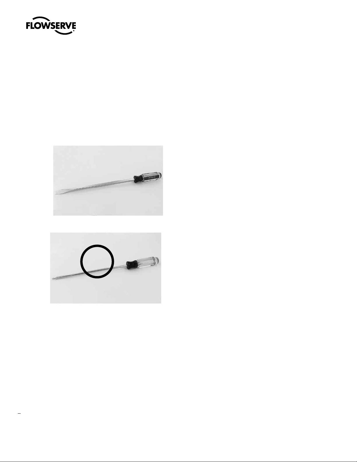
NOTE: Mechanical assistance may be required to remove and
tighten the threaded covers. A flat edge screwdriver 10 inches or
longer may be of assistance.
NOTE: It is not necessary to remove the indicator dome on the
Controls Cover for removal.
Flat Edge Screwdriver (recommended)
Round Edge Screwdriver (not recommended)
Operation
C-PRO version
The C-PRO, ON/OFF voltage control actuator ships from the factory
calibrated and ready to operate. It is not necessary to remove the Controls
Cover if factory settings are suitable. Wire the actuator according to the
wiring diagram located inside the Terminal Block cover.
Key default settings include:
• Factory calibrated for 0-90 degree operation
• CCW to Open, CW to Close
• Fastest operating speed (listed on nameplate)
• Maximum rated torque (listed on nameplate)
• L1 and L2 are for input voltage 120 or 240VAC (Consult Factory for
other AC/DC voltages)
• Terminals 20, 21, 22 and 23
- Terminal 20 = voltage command common
- Terminal 21 = voltage command OPEN
- Terminal 22 = voltage command CLOSED
- Terminal 23 = voltage command MID
• Terminals 1 and 2 are Normally Open (NO) dry relay contacts for
OUTPUT 1 (CCW)
X
After commissioning the actuator, the threaded cover(s) will need to be
installed in reverse fashion. Rotate by hand until difficult to turn (about
90% complete). Use mechanical assistance until you feel the cover
“bottom out.” For the controls cover to be properly sealed, the gap
between the cover and the housing should be no more than 0.010 inch.
With the actuator in full CW position, the entire RED closed indicator
should be shown in the viewing window of the dome. This is the
factory default setting. User may change to CCW/Open position.
WARNING: All threaded covers must be installed with the above
a
criteria, otherwise NEMA/IP and Hazardous Area ratings could
be compromised.
6
• Terminals 3 and 4 are Normally Open (NO) dry relay contacts for
OUTPUT 2 (CW)
• Terminals 5 and 6 are Normally Open (NO) dry relay contacts for
OUTPUT 3 (Torque or MID)
• Terminals 7 and 8 are Normally Open (NO) dry relay contacts for
OUTPUT 4 (Compartment Temp)
NOTE: L1 and L2 are to be powered at all times. Remote voltage
commands can be any voltage between 24VDC-240VDC or
24VAC to 240VAC: 4/5 wire power and control scheme.
For 3 wire power and control scheme, consult Flowserve.
Page 7
Limitorque Worcester Controls CEA Series FCD WCENIM2080-00-AQ 12/14
C-MOD version
The C-MOD or Modulating control actuator ships from the factory
calibrated and ready to operate. It is not necessary to remove the Controls Cover if factory settings are suitable. Wire the actuator according
to the wiring diagram located inside the Terminal Block cover.
Key default settings include:
• Factory calibrated for 0-90 degree operation
• Direct Acting CCW to Open
• L1 and L2 are for input voltage 120 or 240VAC (Consult Factory for
other AC/DC voltages)
• Terminals 11, 12, 13 and 14
- Terminal 11 = + 4-20mA current source (input)
- Terminal 12 = ( - ) 4-20mA current source (input)
- Terminal 13 = + Loop Powered 24VDC + 4-20mA current
(output)
- Terminal 14 = ( - ) Loop Powered 24VDC + 4-20mA current
(output)
• Terminals 1 and 2 are Normally Open (NO) dry relay contacts for
OUTPUT 1 (CCW)
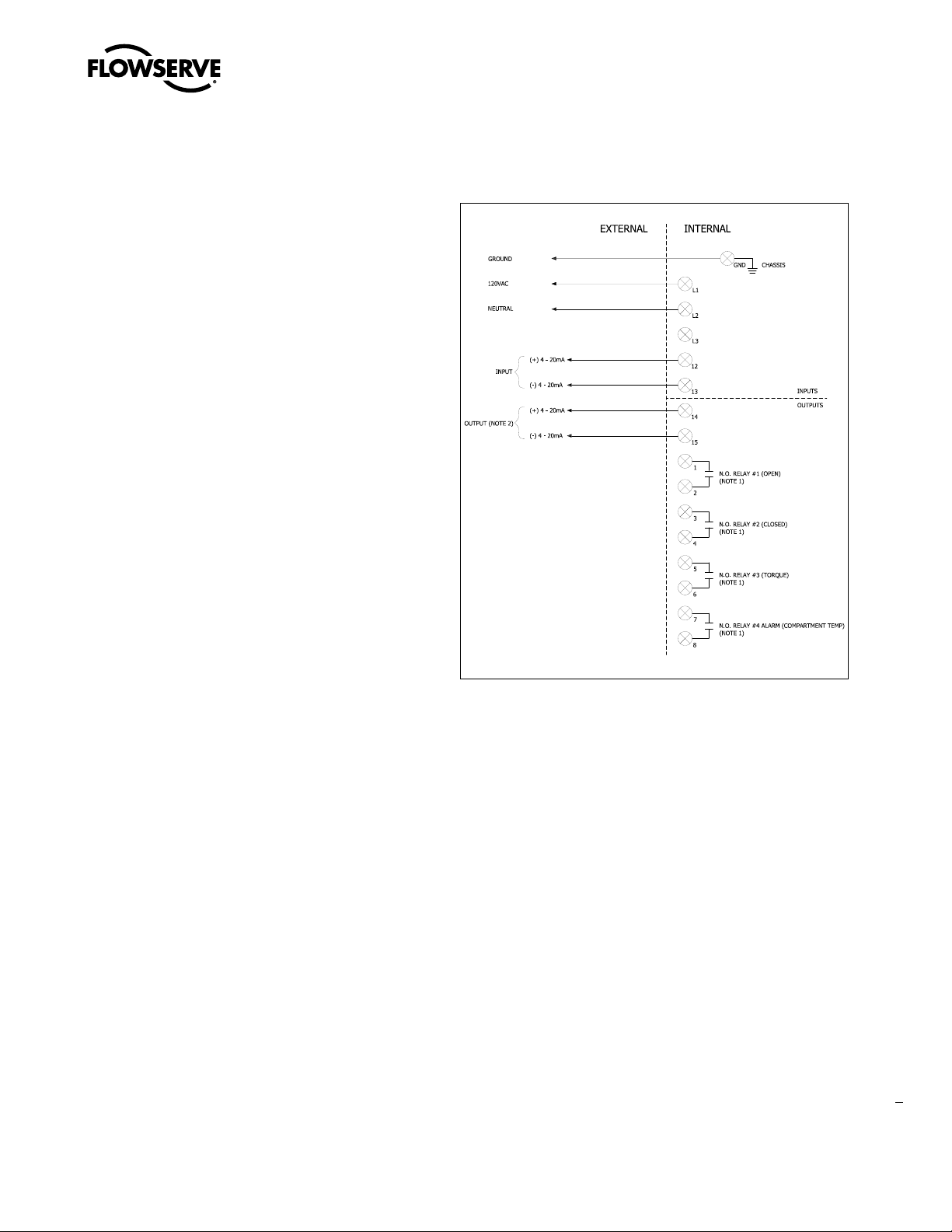
2.1 C-MOD Wiring
• Terminals 3 and 4 are Normally Open (NO) dry relay contacts for
OUTPUT 2 (CW)
• Terminals 5 and 6 are Normally Open (NO) dry relay contacts for
OUTPUT 3 (Torque or MID)
• Terminals 7 and 8 are Normally Open (NO) dry relay contacts for
OUTPUT 4 (Compartment Temp)
NOTE: L1 and L2 are to be powered at all times
NOTE: 4-20mA output is to be loop powered with 24VDC.
Voltage range 13-24VDC.
NOTE 1: Contact rating = 16amp @ 250VAC, dry contact. All outputs
are programmable, remote voltage inputs are 12VDC
to 240VAC for Open, Closed, Mid/Dribble terminals
(20,21,22,23)
7
flowserve.com
Page 8
Limitorque Worcester Controls CEA Series FCD WCENIM2080-00-AQ 12/14
2.80
71.02
3.17
80.50
10.13
257.19
.64
16.16
5.82
147.84
4.84
122.83
REVISION HISTORY
REV
EC/SO
DESCRIPTION
DATE
BY
APPV
0 5933
INITIAL RELEASE
8/15/13
BMN
MDR
1 5998
DIMENSION "W" FOR 0.875-1/4x3/16 BORE TORQUE NUT IN
THE TABLE WAS CHANGED FROM 0.188 TO 0.250
12/3/2013
JDE
JDE
2 00001713
DRAWING RE-LINKED TO LATEST ASSEMBLY FILE CY102215A
6/17/2014
THIRU
JDE
3 00002000
ADDED LARGE BOLT CIRCLE DIMENSIONS
7/23/14
BMN
MDR
4 00002090
ADDED DUAL DIMENSIONS TO OVERALL DIMENSIONS
8/6/2014
JDE
DRM
D
C
B
6
5
4
3
2
1
E
F
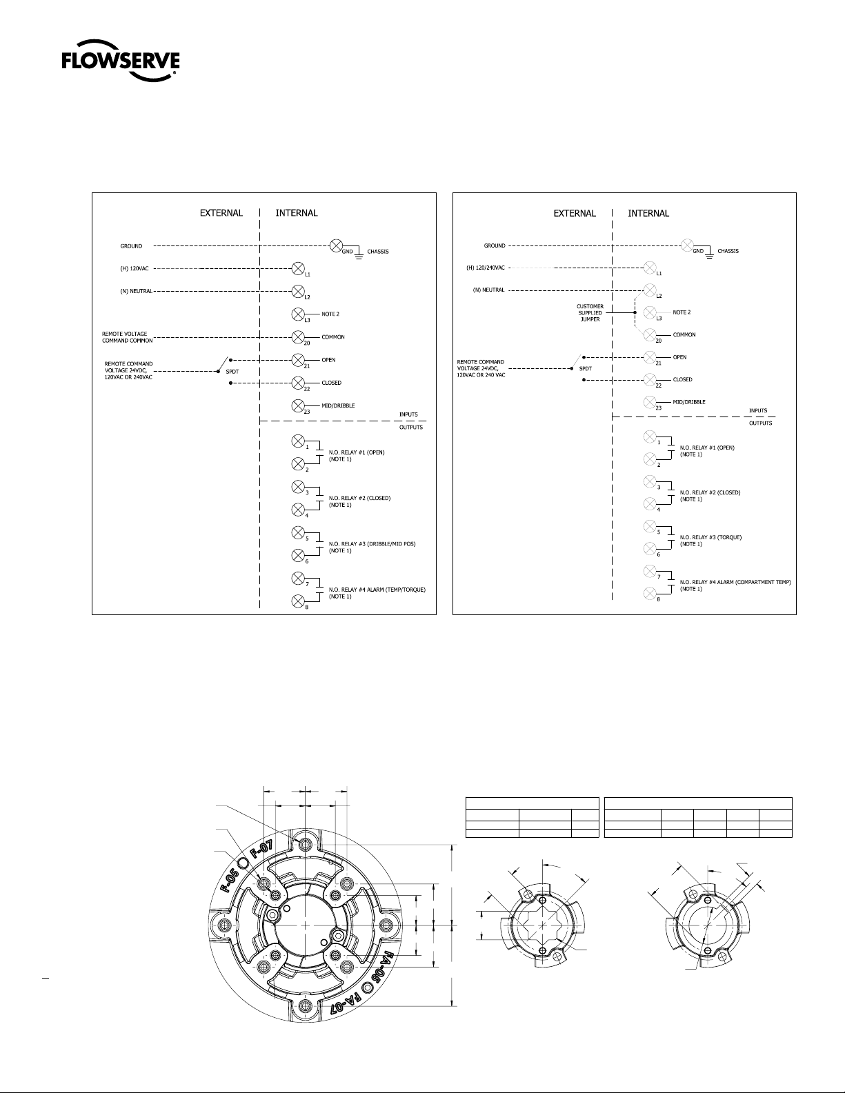
C-PRO Wiring
ON/OFF with Isolated Voltage Command Control
C-PRO Wiring
ON/OFF with Non-Isolated Voltage Command Control
NOTE 1: Contact rating = 16amp @ 250VAC, dry contact. All
outputs are programmable, remote voltage inputs are
12VDC to 240VAC for Open, Closed, Mid/Dribble terminals
(20,21,22,23).
NOTE 2: 208 - 240VAC, 3 phase (future)
Standard Baseplate Mounting
M8x1.25 - TAP
0.51 DEEP
(F07) M8X1 / (FA07) 5/16-18 UNC - TAP
(F05) M6X1 / (FA05) 1/4-20 UNC - TAP
0.67 DEEP
0.51 DEEP
8
.974 .974
.702 .702
.974
.702
.702
.974
DOUBLE SQUARE TORQUE NUT
DESCRIPTION
0.669 0.669 0.787
0.551 0.551 0.630
1.890
TYP.
1.890
TYP.
+-.004
"A"
.000
+-.004
"A"
.000
DOUBLE SQUARE TORQUE NUT
"A" (SQUARE)
45°
DEPTH
R.08 MAX.
TYP.
DESCRIPTION
0.875-1/4x1/4
0.875-1/4x3/16
"BORE"
BORE TORQUE NUT
"BORE"
0.879 0.991 0.250
0.879 0.960 0.250
+-.008
"T"
.000
+-.004
.000
BORE TORQUE NUT
"T"
"W"
DEPTH
"W"
+-.002
.000
1.63
1.63
45°
MOUNTING
BLANK TORQUE NUT
(F05/FA05 & F07/FA07)
Page 9

2.2 Menu Tree
Full Menu show LCS Pos graph BakEMFFaul
Read Statistics Reset stats IRAM Fault
Diagnostic HWOv erTorq
Man/Auto AUT, OK=MAN MAN,OK=AUTO COP Fault
IGBT Short
Full Menu
Setup Full
linear*
Character equal %
quick open
custom
sqr root
# of points
Custom char custom curve
0% = 4.0mA*
Current range 100% = 20.0mA* free*
cutoff free* Cutoff Low L O = 1.0%
Set low limited cut off Cutoff High HI = 99.0%
Trvl ctrl Set high limited Limit Low LO = 0.0%
Values Limit High HI = 100.0%
Direct
Transmitter Direction Reverse Position
Pos/Set Setpoint
Setpoint %*, mA, degrees
Position %*, degrees Position
Language Torque Nm, Lb-in*, Lb-Ft Set & Pos*
Appearance Units Temp C, F*, K Set & Dev
Default Display Menu
Start Logo On*/OFF
Orientation Norma l*,Flipped
HW rev Message
SW rev Tag
Devicedata Capa bility Descriptor
HART/MBUS Date
Device ID ID = XXXXXX (= serial no)
Modbus adr ADDR = XXX
Assembly No.
Tuning Clos e Time MIN = 0.0s Universal Cmd Rev
Open Time MIN = 0. 0s Special Cmd Rev
Deadband D = 1.0% Burst
Expert
Control PID Parameters
Stroketime CCW = X.Xs
CW = Y.Ys
FACT SET (press OK for 3 se conds to set default settings)
Read
MAN/AUTO
Calibrate Duplicated - se e Basic Menu tree
Setup Pro
Status
Protection
Note: (*) indicate s factory default setting
Slow shaft detection percentage
Unit address
C-MOD Dedicated
Character
Custom char
Current range (sp lit range)
Trvl ctrl
Loss of setpoint signal position
Loss of setpoint signal time
Setpoint selector
Loss of position feedback action
Limitorque Worcester Controls CEA Series FCD WCENIM2080-00-AQ 12/14
C-PRO & C-MOD Menu Tree - SW120
Basic Menu* Standard* 1 (Pos*/Alarm) Show alarm
Calibrate Rotation Mid Pos 4 (Pos/Alarm*) Limit 2
Set Up Pro Torque Closed
Outputs ALARMS Torque
AutoCal Compa temp
Expert Cal Set Point Model Motor temp
Speed
Direction Open Speed
Curr Limit CCW/CW Close Speed
Transm Open
Turns 2 (Pos*/Alarm) Deviation
Manual 3 (Pos/Alarm*) Limit 1
Status 0 0 Service N cycles Lo MotrVlt
Protection NO* Set & Dev # of reset IGBT Op en
Shift Basic Menu* comp temp Histogram Ha llldxLmp
IN Service* Pos Acc travel MotrTmpOOR
YES Enter Code Torque Run time Ha llldxCrt
Set & Pos* Mean dev MotrOvrTrq
motor temp Extreme Temp PMCB Reset
Full Menu
Shift Basic Menu
9
flowserve.com
Page 10

10
Limitorque Worcester Controls CEA Series FCD WCENIM2080-00-AQ 12/14
Basic Menu
Calibrate
Setup Pro
Status
Protection
Shift
Read
Man/Auto
Calibrate
Rotation
Standard
90, 180, 270, 360, Multi
Turns
set turns (1,6,10,12,17,20)
Manual
subset of Standard Rotation,+/- 6 degrees of min/max rotation.
(i.e. if 90 selected, select value (-)6 - (+) 96 (XX); 180 selected, select (-)6 - 186 (XXX)
Mid Positio (dribble Off/On)
subset of Standard Rotation,+/- 6 degrees of min/max rotation.
(i.e. if 90 selected, select value 5 - 85 (XX); 180 selected, select 5 - 175
Outputs (XXX) Factory Default
1 (Pos/Alarm)
2 (Pos/Alarm)
3 (Pos/Alarm)
4 (Pos/Alarm)
ALARMS
Show alarm
Deviation
Limit 1 Limit
2 Torque
Compa temp
Motor temp
AutoCal
start cal (press "OK"), note: must be Out of Service
Expert cal
Set Point (Setpoint LO, Setpoint HI)
Transm (Transm low, Transm hi)
Set Up Pro
Torque Factory Default (Max per model size)
Model
Open torq
Close torq
15, 60, 150, 250, 500
100%, 95%, 90%, …(10 selections 100% - 40%)
Speed Factory Default (fastest per model size)
Open speed
5,10,15, 20…180 (10 selections min to max)
Clos speed
5,10,15, 20…180 (10 selections min to max)
Direction
CCW or C (define the parameter) Factory Default
(CCW) Current Limit
1, 1.5, 2,2.5, … to max (selectable with 0.5 amp increments up to 10 amp) Factory Default (5 amp)
Status
0 0 service
in service
Protection
Shift
Basic Full
menu
Pos
Set & Pos
Set & Dev
Torque
motor temp
comp temp
show LCS
Statistics
Man/Auto
Auto
Man Set
(press "OK", enter 4 digit code)
(No/Yes)Read Factory Default (Set & Pos)
N cycles (define parameter)
Acc travel
Mean dev (modulating only)
# of reset
Run time (power on time)
Extreme Temp (hi, l
Histogram
Pos graph
Reset stats
Diagnostic
Pos - CCW
Pos - CW
Alarm - compartment temp
Alarm - Torque
(No/
Yes)
ow)
Page 11

Limitorque Worcester Controls CEA Series FCD WCENIM2080-00-AQ 12/14
3. Installation and Operation
Description
Flowserve CEA actuators are reversible electric rotary valve
actuators. Standard units can provide up to 5000 in-lb of torque and
use a Brushless DC (BLDC) motor and permanently lubricated gear
trains. These actuators are equipped with integral thermal overload
protection with automatic reset and electronically adjustable position
and rotation limit switches. In the event of electrical power failure, all
models feature manual override capabilities.
WARNING: SERIES CEA ACTUATORS ARE
a
ELECTROMECHANICAL DEVICES SUBJECT TO NORMAL
WEAR AND TEAR. ACTUATOR LIFE DEPENDS UPON
APPLICATION AND ENVIRONMENTAL CONDITIONS. IF
APPLIED IN HAZARDOUS SERVICES, SUCH AS BUT NOT
LIMITED TO, MEDIA TEMPERATURE EXTREMES, TOXINS,
FLAMMABLES, OR OTHER SERVICES WHERE IMPROPER OR
INCOMPLETE OPERATION COULD PRODUCE A SAFETY
HAZARD, IT IS INCUMBENT UPON THE SYSTEM DESIGNER
AND THE USER TO PROVIDE PROPER WARNING DEVICES
SUCH AS TEMPERATURE SENSORS, OXYGEN SENSORS AND
FLOW SENSORS. AT ELEVATED TEMPERATURES THE DUTY
CYCLE HAS TO BE DERATED, CONSULT FACTORY.
FLOWSERVE ALSO RECOMMENDS THAT THE OPTIONAL
AUXILIARY LIMIT SWITCHES BE USED FOR MONITORING
AND/OR ELECTRICAL INTERLOCK.
CAUTION: If necessary, Flowserve recommends indoor, controlled
a
temperature storage of all products prior to installation. Do not
store product in areas with exposure to relative humidity above
85%, acid or alkali fumes, radiation above normal background,
ultraviolet light, or temperatures above 120°F or below 40°F. Do
not store within 50 feet of any source of ozone.
CAUTION: FOR WIRING OF ACTUATOR, INCLUDING OPTIONS,
a
PLEASE REFER TO WIRING DIAGRAM(S) LOCATED INSIDE OF
ACTUATOR TERMINAL BLOCK COVER. Wiring diagrams are also
included in this manual on pages 6 and 7 for reference.
CAUTION: The gear train compartment is oil filled. High perfor-
a
mance Mobil 1 oil is used for standard temperature requirements.
The compartment volume is 12oz. Oil replacement is not required
under normal operating conditions.
3.1 Installation – Flowserve Automax Valve Products
1. Attach mounting bracket to actuator using the four (4) screws and
lockwashers provided in the mounting kit, and tighten securely.
For small size, top mount style valves, attach bracket so the
bracket nameplate will be to the side of the valve.
2. Attach bracket/actuator assembly to valve as follows:
NOTE: If cross-line mounting of actuator is desired, note the
following: Mount the actuator with conduit hole perpendicular to
the flow axis (center line) of the valve and reverse the open/close
decals.
For diverter and three-way valves with V1 porting, and CPT valves,
also see Electrical Installation and Adjustment Section for cam and
limit switch adjustments to facilitate cross-line mounting operation.
CAUTION: Ball valves can trap pressurized media in the cavity.
a
If the valve is or has been in operation and it is necessary to remove any valve body bolts, stem nuts, or the valve from the line,
make sure there is NO pressure to or in the valve and operate the
valve one full cycle before and after removal.
Valve Models Top Mount 44 (1/4”–2”), 45 (2.5”–6”), 51/52 (1/2”–
10”), 151/301 (3”–6”), Top Mount 59 (1/4”–4”), WK70/WK74 and
H71 (1/2”–2”), 818/828 (2”–8”), 82/83 (1/2”–10”) and 94 (1/2”–6”):
NOTE: For above listed valves, it is not necessary to remove any
valve body bolts or the valve from line in order to mount the
actuator.
3. Close valve:
• For valves 1/4”–2”, the valve is closed when flats on valve stem
are perpendicular to the line of flow.
• For valves 3” and larger, where the valve stem is square, the
indicator line on top of stem will be perpendicular to the line of
flow or check ball position for closure.
• If any valve information is marked on stop plate or handle, it
will be necessary to transfer this information to the bracket
nameplate.
For 1/4”–2” 44 and 1/2”–2” WK70/WK74, 1/4”–1 1/2” 59 and 1/2”–2”
H71 Series top mount style valves and 1/2”–2” 51/52, 1/2”–1 1/2”
82/83 Series valves with high cycle stem packing as standard:
4. Remove handle nut, lockwasher, handle, separate stop plate (if
any), retaining nut and stop pin(s).
5. Add the two additional Belleville washers with their larger diameter sides touching each other.
6. Add the self-locking nut to the stem and tighten while holding the
stem flats with wrench.
7. Tighten until Belleville washers are flat, the nut will “bottom”, and
then back nut off 1/3 turn. The two additional Belleville washers
and the self-locking nut are included in the mounting kit.
CAUTION: The self-locking stem nut is difficult to tighten and
a
must fully flatten Belleville washers before backing off the nut by
one third of a turn.
For 2” 59, H71, 82/83, and 2.5” 45, 82/83 Series valves and valves
3” and larger with square stem, remove handle assembly (if any),
retaining nut, stop and stop screws.
Replace with valve stem spacer or, if valve has graphite stem packing,
11
flowserve.com
Page 12

Limitorque Worcester Controls CEA Series FCD WCENIM2080-00-AQ 12/14
with two Belleville washers (except 8”, 10” 82/83 and 10” 51/52) and
replace retaining nut.
NOTE: Belleville washers are installed with larger diameters so
they are touching each other. Using a wrench to prevent stem
from turning, tighten retaining nut until the stem packing is fully
compressed or until Bellevilles (if used) are fully flattened. Then,
back off nut 1/6 turn. Excessive tightening causes higher torque
and shorter seal life.
NOTE: 3” size and larger valves with V51 high cycle stem
packing (no handle assembly) are ready to automate without
modification.
For 1/2”–2” 94 valves, remove handle (if any). For 3”–6” 94 and 2”–8”
E818/E828 valves, remove handle assembly, stop, and spacer (if any).
Do NOT remove gland plate or gland bolts.
For 2”–8” 818/828 valves, remove handle assembly, locking plates
and hardware, and stop screw (if any). Do not remove stop plate
(2”–6” sizes) or spacer (8” size).
1. Center coupling on valve stem.
2. Lower mounting bracket/actuator assembly over coupling and
onto valve, making sure that male actuator shaft engages slot in
coupling.
3. Secure bracket to valve using cap screws and lockwashers, or
bolts and nuts provided in mounting kit. Tighten securely. For
small size top mount style valves, bracket nameplate will be to
side of valve.
4. Install set screws (if any) in the coupling and tighten securely.
tor housing. Connect power supply to actuator terminal strip as
shown on electrical schematic diagram(s) located inside terminal
block cover and also in this manual.
The actuator should be electrically grounded in accordance with
standard procedures.
See table below for minimum fuse rating when overcurrent protection
is used in motor power circuit.
Minimum Fuse Rating for Overcurrent Protection
Actuator Size Voltage Fuse Rating (A)
15/60/150 120 VAC 2A
15/60/150 240 VAC 1A
15/60 24 VDC 3A
150 24VDC 5A
NOTE: The table shows the minimum rating to prevent in-rush
current from blowing the fuse.
4. Calibration and Commissioning
The CEA actuator ships from the factory calibrated for 0-90 degree
rotation.
4.1 Travel Stop Adjustment
CAUTION: do not rotate travel stops counter clockwise (CCW)
a
beyond the inward/second “position orientation” groove as this
will result in oil leakage. If accidentally rotated beyond this position and leakage is observed, adjust clockwise (CW) to reposition
to the sealing zone between the two position grooves.
12
3.2 Electrical Installation and Adjustment
NOTE: The CEA actuator has 3 threaded covers on the actuator
housing: Controls cover, Terminal Block cover and Motor cover.
Cover(s) use an O-Ring to provide environmental sealing and
proper installation/assembly is required to prevent moisture
ingress.
ATEX hazardous area installation
Each cover incorporates a locking bracket attached by a screw that
must be loosened prior to cover(s) being removed.
Each cover is designed with 4 raised tabs and mechanical assistance
is required to remove the cover. A common “tool belt” screwdriver, 10
inches or longer, is recommended for mechanical assistance. Place
the tool between 2 adjacent tabs and rotate counter clockwise (CCW)
to remove the cover. Once O-Ring compression is relaxed the cover
will rotate freely by hand.
A. To gain access to terminal block, it is necessary to remove the
terminal block cover
B. Make conduit connection(s) to NPT/Metric fitting taps on actua-
CAUTION: it is not recommended to use the travel stops to
a
control normal rotation. Rotation limits should be electronically
set using the HMI menu Calibrate/Rotation with travel stops set
1-2 degrees outside calibrated rotation
Mechanical travel stops are provided on 90 degree rotation units to
provide over-travel protection. They are adjustable to provide +/- 6
degrees of adjustment. They are factory set 1-2 degrees outside the calibrated rotation. Adjust CW to reduce travel and CCW to extend travel.
One 360 degree rotation provides 3.2 degree position output change.
Each travel stop bolt has 2 position orientation grooves to identify the
min and max rotation position. Adjustment must be maintained within
these 2 grooves. CCW rotation beyond the inward groove will result in
potential oil leakage.
To calibrate the unit after a travel stop adjustment, simply navigate
using the arrow down key to the CALIBRATE menu and then to AUTO
CALIBRATE and select OK. This will recalibrate the actuator to the new
travel stop endpoints.
Please note that if any adjustments are made to the travel stops due to
mount issues or special valve requirements then the unit will require a
field AUTO CALIBRATION before it is placed IN SERVICE.
Page 13

Limitorque Worcester Controls CEA Series FCD WCENIM2080-00-AQ 12/14
4.2 Gear Train
A precision cut bronze or ductile iron worm gear set delivers maximum strength and durability. For optimum performance the gear set
is permanently lubricated and submerged in oil in a sealed compartment.
High performance Petro Canada Syndro SHB-68 oil is used for standard temperature requirements. The compartment volume is 12oz. Oil
replacement is not required under normal operating conditions.
Options and Adjustments (Factory Installed)
Magnetic Rotary Positioner Sensor
Shaft position feedback is accomplished using a 12-bit magnetic
rotary position sensor directly coupled to the output drive. Specifically
designed for brushless DC (BLDC) motor control, this technology
provides the highest accuracy and reliability.
Position and Alarm Outputs
4 outputs are provided as standard and pre-wired to the terminal
block. Standard outputs are non-latching, dry contact,15A rated.
Optional latching contacts are available; consult Flowserve.
Outputs may be configured for remote position indication and/or
alarm feedback.
When alarms are activated, additional “action” may be programed:
> DO NOTHING (factory default)
> GO to OPEN
> GO to CLOSED
> MANUAL MODE
Also note that the relay stays energized during an alarm condition. It
deenergizes when the value is outside of the MIN/MAX range entered.
Factory default settings:
Output 1: position CW
Output 2: position CCW
Output 3: Alarm High Torque
4.3 Rotation Speed Control
Selectable Rotation Times
Nominal
Model
150 1500(170) 10* 12 15 20 30 50 80 110 150 180
*Factory Default
Torque
in-lbs
(Nm)
15 150(17) 5.0* 7.5 10 15 20 50 80 110 150 180
60 600(68) 5.0* 7.5 10 15 20 50 80 110 150 180
o
rotation time in seconds
90
Rotation speed is factory set to the fastest 90 degree rotation per the
actuator model code specification (Example: M60 = 5 seconds). Both
the CCW and CW rotation speed is independently adjustable with 10
pre-set selections that increase rotation speeds up to 180 seconds.
4.4 Variable Torque Output
Selectable Torque Output
Nominal
Model
150 1500 (170) 100* 95 90 85 80 75 70 60 55 40
*Factory Default
Torque
in-lbs
(Nm)
15 150 (17) 100* 95 90 85 80 75 70 60 55 40
60 600 (68) 100* 95 90 85 80 75 70 60 55 40
Torque times percent equals maximum output torque
(valves listed below are percent (%)
Example Model 60: 600 in-lbs set at 100% = 600 in-lbs;
set at 75% = 450 in-lbs.
Torque output is factory set to the maximum value per the actuator model code specification (example: M60 = 600 in.lbs.). Output
torque is adjustable from 100% to 40% of rated value with 10 pre-set
selections.
4.5 Duty Cycle
Model Open/Close Service Modulating Service
15 360/hr 1800 Starts/hr
60 360/hr 1800 Starts/hr
150 180/hr 1800 Starts/hr
Output 4: Alarm Compartment Temperature
The CEA actuator is rated for 1800 starts per hour, under full load
conditions, within the normal operating temperature limits per
specification listing.
4.6 Heater and Thermostat
Heaters are not required for operation to -40C and/or to control
condensation. Condensation does not occur due to non-breathing
enclosure and internal compartment temperature stabilization. The
customer may order a factory-installed heater and thermostat if
desired.
flowserve.com
13
Page 14

Limitorque Worcester Controls CEA Series FCD WCENIM2080-00-AQ 12/14
ATTENTION: Actuator is factory calibrated for standard
rotation, max speed, max torque and output settings per model code
on nameplate. Unit ships with Output shaft in the CW position for
mounting. Standard rotation is CCW to Open, CW to Close.
HMI Interface (see IOM for complete detail)
The actuator is User configurable using the 5 push
bottons and the display. Default display is position.
Press the ESC button to display the Main Menu. Use the
UP/DN push buttons to browse through the Main Menu
and Sub-Menus.
OTHER FUNCTIONS:
ESC- exit the menu or return to previous level
FUNC - Select a function and change parameters
OK- To confirm a citical selection or change of parameters
In Service - Normal status, actuator responds to remote
commands
Out of Service - Actuator off-line, critical parameters may be
changed
Manual - Actuator rotation may be adjusted manually via
push buttons
Unprotcted - Parameters may be changed without
passcode
MENUS:
Basic Menu - Supports primary setup (read, man/auto, calibrate, setup, status, protection,
shift); Use status to change service and shift to advance to full menu
Full Menu - Supports advanced configuration
Analog Output
Available option will provide analog 4-20mA continuous position
feedback.
CAUTION: In cases where the conduit connected to the actuator
a
may be partially or completely run underground, or through which
moisture may contact energized live parts, or where the actuator
and/or conduit is exposed to temperature differences, the conduit
should be sealed within 18” of the actuator in accordance with the
National Electrical Code.
When electrical installation is complete, it is advisable to check the
indexing of the actuator to ensure proper valve rotation.
Replace actuator cover(s).
NOTE: The CEA actuator has 3 threaded covers on the actuator
housing: Controls cover, Terminal Block cover and Motor cover.
Each cover is designed with 4 raised tabs and mechanical assistance is required to properly secure the cover. A common “tool
belt” screwdriver, 10” or longer, is recommended for mechanical
assistance. Rotate the cover by hand until difficult to rotate.
Place the tool between 2 adjacent tabs and rotate clockwise (CW)
to properly secure/install the cover (approximately 1.5 additional
turns).
Cover is properly installed when no cover-to-housing gap is visible.
Use a feeler gauge according to the listed procedure to confirm.
If using the ATEX locking tab, tighten screw to secure tab.
Feeler Gauge Procedure
Use a .010 inch feeler gauge inserted at the location of the nameplate
just above the word MODEL, between the housing and controls cover.
The feeler gauge should feel tight and be inserted approximately .060
inches
4.7 HMI Display
Menus and Push Buttons
The actuator is user configurable using the five pushbuttons and the
LCD display, which are accessible when the top Controls Cover is
removed. For normal functioning, the display shows the current value.
Press the ESC button for two seconds to display the main menu.
Other Functions
ESC
Exit the menu without making any changes (as long as any changes
have not been confirmed with OK).
FUNC
To select function and change parameters.
OK
To confirm selection or change of parameters.
MENU INDICATOR
Displays the position of the current menu row in the menu.
IN SERVICE
The actuator will respond to discrete input commands. This is the
normal status when the actuator is working properly.
OUT OF SERVICE
The actuator will not respond to discrete input commands. Critical
parameters can be changed.
MANUAL
The actuator can be adjusted manually using the pushbuttons. See
section ”Man/Auto”, page 15.
UNPROTECTED
Most of the parameters can be changed when the actuator is in the
”Unprotected” position. However, critical parameters are locked when
the actuator is in the ”In service” position.
Menus:
Use the Up/Dn buttons to browse through the main menu and the
sub-menus.
14
OUT OF SERVICE
MANUAL
BASIC MENU
MAN/AUTO
UNPROTECTED
ESC
OK
FUNC
Page 15

Menu Indicator
There are indicators at both sides of the display window and they
indicate as follows:
Flashing in position
Out of service
FULL MENU
MAN/AUTO
Flashing in position Manual
FULL MENU
CALIBRATE
Displayed in position
Unprotected
FULL MENU
SHIFT MENU
Limitorque Worcester Controls CEA Series FCD WCENIM2080-00-AQ 12/14
Menu System
Basic Menu Full Menu
Calibrate Shift Menu
Setup Pro Setup Full
Status Tuning
Protection Fact Set
Shift Menu Read
Read Man/Auto
Man/Auto Calibrate
Setup Pro
Status
Protection
BASIC MENU
READ
BASIC MENU
MAN/AUTO
BASIC MENU
CALIBRATE
BASIC MENU
SETUP PRO
The indicators on the right-hand side show the position in the current
menu.
Menus
To display the menus you can select:
- Basic menu, which means you can browse through seven different
steps
- Full menu, which comprises ten steps. Use the Shift Menu to
browse through the steps
Full Menu can be locked out using a passcode.
The main menus and sub-menus are shown on the following pages.
4.8 Programmable Parameters
Changing Parameter Values
Change by pressing until the desired figure is flashing.
Press to step to the desired figure. Confirm by pressing OK.
A change can be undone by pressing the ESC button, which returns
you to the previous menu.
BASIC MENU
STATUS
BASIC MENU
PROTECTION
BASIC MENU
SHIFT MENU
flowserve.com
15
Page 16

Limitorque Worcester Controls CEA Series FCD WCENIM2080-00-AQ 12/14
The menu contents are shown in the figures on the right and the texts
are described below:
BASIC MENU
CALIBRATE
Calibrate/Rotation:
The Calibrate Menu is used to calibrate rotation variations, discrete
outputs, Auto Calibration and Expert (advanced) Calibration. 4 configurable parameters are available: Standard, Turns, Manual and Mid
Position.
1. Rotation/Standard: depending on product model, multiple
rotation angles are available for selection. Option examples: 90,
180, 270, 360, Multi
2. Rotation/Turns: multiple 360o rotation turns are available for the
multi-turn (MT) option only
3. Rotation/Manual: the user may manually select alternate
positions for CCW/Open and CW/Closed rotation.
a. A known value may be entered (i.e. 0% = 10.0% or 100% =
70%) to change rotation position.
b. Use Set 0% or Set 100% and press the Up/Dn arrow to
“step” position changes in 0.5% increments. Press “OK”
button for 3 seconds to accept the new value. CAUTION:
do not rotate outside the factory calibrated 0% and 100%
positions without first adjusting the associated Travel Stop
bolt CCW. This will prevent driving the output gear into the
mechanical stop.
4. Rotation/Mid Position: Mid Position parameter is used for
3-position control (i.e. multi-port 3-way valves). To enable: go
to Rotation/MIDPOS/dribble – select ON; next: mid = 050.0%
(example); next: set midpos/press “OK” for 3 seconds.
Calibrate/Outputs:
The CEA provides 4 discrete programmable outputs. Each output
may be configured for either Position Output or Alarm Output. Alarm
outputs are further programmable to perform specific Valve Action
when activated. See section 4.8 and 4.9 for more detail.
Calibrate/Expert Cal
This parameter provides advanced calibration for analog setpoint
input and analog output.
1. Analog setpoint input may be configured for minimum signal
input (i.e. LO = 4.0mA) and maximum signal input (i.e. HI =
20.0mA)
2. Analog output option should be calibrated to match the rotation
minimum and maximum positions (i.e. Transm low/LO = 4.0ma;
Transm hi/HI = 20.0mA)
BASIC MENU
SETUP PRO
The Setup Pro menu is used to calibrate Torque, Speed, Direction and
Current Limit.
1. Setup/Torque: Clockwise (CW) and counterclockwise (CCW) rotation torques may be independently configured using 10 preset
values. Selectable values include: 100%, 95%, 90%... (10 selections 100% - 40%). Values are selected based on percentage
of Rated Torque. For example: rated torque 600in-lbs.: 100% =
600in-lbs.; 50% = 300in-lbs.
2. Setup/Speed: Clockwise (CW) and counterclockwise (CCW) rotation speeds may be independently configured using 10 preset
values. Selectable values are listed in “seconds” and include:
5,10,15,20…180 seconds.
3. Setup/Direction: 2 settings are available CCW and CW. CCW:
When setpoint power is applied to TB point 21, the unit will rotate in the CCW direction. CW: when setpoint power is applied
to TB point 21, the unit will rotate in the CW direction.
4. Setup/Current Limit: The user may select a maximum current
load for the actuator not to exceed. This feature may support
low power DC applications, torque seating and valve “jam”
conditions. Available settings are 1amp up to 10amp in 0.5 amp
increments.
16
Calibrate/AutoCal
AutoCal may be used to recalibrate the actuator at any time. This
feature is most commonly used when rotation values are modified
from factory default. When AutoCal is performed the unit will rotate
to the mechanical stops or electronic limits and automatically update
all 4 outputs for position and/or alarm.
Page 17

Limitorque Worcester Controls CEA Series FCD WCENIM2080-00-AQ 12/14
BASIC MENU /
STATUS
The Status Menu is used to select whether or not the actuator is in
service.
o o service Not in service. Flashing indicator in upper
left-hand corner of display.
in service Positioner in service.
Critical parameters cannot be changed.
STATUS
O O service
STATUS
in service
When changing between
In service and Out of Service,
the OK button must be
pressed for 3 seconds.
OK
OK
OK
OK
BASIC MENU
SHIFT MENU
The Shift Menu is used to choose between the basic menu and the full
menu.
The menu contents are shown in the figures on the right and the
various texts are described below:
No Full menu selected.
Yes Basic menu selected.
Full menu
no
Full menu
yes
Full Menu can be locked with a
passcode, see Setup menu.
OK
OK
OK
OK
BASIC MENU /
PROTECTION
The Write Protect menu is used to protect all essential settings.
No Entered values are not write protected.
”Unprotected” is displayed in the lower
left-hand corner.
Yes Entered values are write protected. Passcode
needed for change to No (Applicable when a passcode has
been set up in SETUP menu).
PROTECTION
no
PROTECTION
yes
When changing between
Yes and No mode, the OK
button must be pressed
for 3 seconds.
OK
OK
OK
OK
17
flowserve.com
Page 18

Limitorque Worcester Controls CEA Series FCD WCENIM2080-00-AQ 12/14
BASIC MENU
READ
Values can be read using the Read Menu and some values can be
reset.
Pos shows current position
Set & pos shows current setpoint
and position
Set & dev shows current setpoint
and deviation
Torque shows current load torque
Motor temp shows current motor temp
Compa temp shows current compartment temp
Statistics shows statistics and
diagnostic data
Statistics
n cycles Shows number of movements
(turns)
Acc travel Shows accumulated
movement
mean dev Shows accumulated deviation in %
runtime Shows accumulated runtime
since last reset
Extr temp Shows extreme min and max
temperature
Histogram Shows position and time for
PV
Alarms Displays tripped alarms
READ
pos
READ
set&pos
READ
set&dev
READ
torque
READ
motor temp
READ
comp temp
READ
statistics
Statistics
n cycles
Statistics
acc travel
Statistics
mean dev
Statistics
# of reset
Statistics
run time
Statistics
extreme temp
Statistics
histogram
Statistics
pos graph
Statistics
reset stats
Statistics
diagnostics
BASIC MENU
MAN / AUTO
The Man/Auto menu is used to change between manual and automatic
modes.
AUT, OK = MAN
Positioner in automatic mode
MAN, OK = AUT
Positioner in manual mode
In the MAN mode, the value of POS can be changed using the UP/
DN push buttons. The push-buttons increase/decrease the value in
steps. The value can also be changed in the same way as for the other
parameter values, as described on page 14.
AUT, OK=MAN
POS= 12.3%
When changing between
MAN and AUT mode, the OK
button must be pressed for 3
seconds.
MAN, OK=AUT
OK
POS= 12.3%
18
Page 19

Limitorque Worcester Controls CEA Series FCD WCENIM2080-00-AQ 12/14
Basic Menu
Outputs - Expanded View
Outputs
1(Pos/Alarm)
2(Pos/Alarm)
3(Pos/Alarm)
4(Pos/Alarm)
Postion
CW/CCW/MID
Alarm
Show Alarm
M, C, 1, 2, D, T
Deviation
ON/OFF
Distance
value=%
Time
value=seconds
Alarm out
on
off
Valve Action
no action
go to close
go to open
manual
Limit 1
ON/OFF
Min Position
value=%
Max Position
value=%
Hysteresis
value=%
Alarm out
on
off
Valve Action
no action
go to close
go to open
manual
Limit 2
ON/OFF
Min Position
value=%
Max Position
value=%
Hysteresis
value=%
Alarm out
on
off
Valve Action
no action
go to close
go to open
manual
Torque
ON/OFF
Min Torque
value=%
Max Torque
value=%
Hysteresis
value=%
Alarm out
on
off
Valve Action
no action
go to close
go to open
manual
Comp Temp
ON/OFF
Min Temp
degrees F
Max Temp
degrees F
Hysteresis
value=%
Alarm out
on
off
19
flowserve.com
Page 20

Limitorque Worcester Controls CEA Series FCD WCENIM2080-00-AQ 12/14
Valve Action
no action
go to close
go to open
manual
Motor Temp
ON/OFF
Min Temp
degrees F
Max Temp
degrees F
Hysteresis
value=%
Alarm out
on
off
Valve Action
no action
go to close
go to open
manual
Status
Man/Auto
Auto (press up/down arrow for options, press enter to
change selection)
Man Set (select value 0-100% (XXX.X) or press up/
down arrows to jog position CW/CCW)
Protection
Shift
Basic
Advanced
4.9 Alarm Output Setup
The actuator is equipped with (4) four configurable outputs. The alarm
OUTPUT parameters are set in the ALARMS menu.
Alarm definitions are as follows:
M= Motor Temperature (Alm mtrtmp)
C= Compartment Temperature(cmptmp)
1=Alarm Limit 1 (Alm Lim 1)
2=Alarm Limit 2 (Alm Lim 2)
T-Torque (Alm Torque)
D=Deviation (Alm dev)
Each alarm can be viewed on the display and/or read by activating the
selectable relay output. If the alarm is set to ON and an alarm condition has occurred, the display will flash. The user can then navigate to
the alarms menu to view the above defined alarm(s). NOTE: The alarm
relay output will not be activated until the alarm is turned on in the
alarms menu.
Basic Menu Calibrate/Outputs/Alarms/Compartment Temp
>>>> ON/OFF
Low temp
High temp
Hysteresis
Alarm out
Valve action
The above setting will indicate an alarm condition by flashing the
display to indicate that one or more alarm conditions has occurred
(M:C:1:2:T:D)
For example, to activate the relay output for compartment temperature, navigate to the ALARMS menu as follows:
20
Basic Menu Calibrate/Outputs/Alarms/Compartment Temp
>>>> ON/OFF
Min temp
Max temp
Hysteresis
Alarm out
>>>> ON
OFF
For example, to set the compartment temperature relay output alarm
to active when the temperature exceeds the MAX value of 125 degrees
F or falls below the MIN value of -5 degrees F, perform the following:
Page 21

Limitorque Worcester Controls CEA Series FCD WCENIM2080-00-AQ 12/14
Basic Menu Calibrate/Outputs/Alarms/Compartment Temp
>>>> ON/OFF
Min temp
>>>> -5
Max temp
>>>> 125
Hysteresis
Alarm out
>>>> ON
All (4) four relay outputs are configured in the same manner. Below is
a list of the parameters.
Alm dev
Alm Lim 1
Alm Lim 2
Alm Torque
Alm mtrtmp
cmptmp
The default outputs are as follows:
4.10 Positioner Indicator
High visibility position indicator is standard with each actuator.
Indicator rotation is accomplished using high performance neodymium magnets that eliminate cover shaft holes and potential path for
moisture ingress.
Indicator is self-indexing and does not require removal to remove the
top cover.
Dome Indicator Adjustment
The dome indicator will come preset from the factory. The indicator
will display CLOSED in the clockwise (CW) position in the viewing
window. The indicator dome may be rotated 90
the CW position.
The dome indicator also has adjustment slots to further align the OPEN
and CLOSED display after the controls cover is completely tightened
down. Loosen the 4 pan head screws that hold down the dome and
rotate CW or CCW as needed. The screws holding down the dome
should only be loosened (not removed) to ensure that the O-ring under
the dome is not pinched when the screws are re-tightened.
o
to display OPEN in
OUTPUT 1= CCW (activates upon full CCW travel. NOTE: normally
open dry contact closes)
OUTPUT 2=CW (activates upon full CW travel. NOTE: normally open
dry contact closes)
OUTPUT 3 = TORQUE (activates when torque is below the low limit or
above the high limit NOTE: normally open dry contact closes)
OUTPUT 4 = COMPARTMENT TEMPERATURE (activates when torque
is below the low limit or above the high limit. NOTE: normally open
dry contact closes)
Setting the dome indicator and internal magnet puck inside the
controls cover
flowserve.com
21
Page 22

Limitorque Worcester Controls CEA Series FCD WCENIM2080-00-AQ 12/14
Magnet Puck Adjustment
If for any reason the black plastic EMC/EMI controls cover is removed
the indicator “puck” magnet will need to be timed such that the correct indication will be shown on the dome window when the actuator
controls cover is screwed down to the proper height.
Prior to adjustment the actuator must be in the Closed/CW position.
Using a 3/32 hex head wrench, loosen the socket head cap screw
and align the wrench with the controls cover set tab located on the
housing. See Figure below.
22
5. Manual Override
Manual override is provided as standard with each actuator. The
override requires minimum force to operate (less than 7lbs force) and
is spring loaded, push to engage. When engaged the worm shaft is
declutched from the motor drive to provide safe operation. The spring
loaded design ensures the override will not accidentally be left in the
By-Pass condition.
NOTE: If power is present and the handwheel is engaged and
rotated, the motor will power on but not impact rotation.
Page 23

Limitorque Worcester Controls CEA Series FCD WCENIM2080-00-AQ 12/14
6. Performance and Technical Data
Performance Specifications
Output
Torque
(Continuous
Start/Run
Torque)
Stall
Torque
(1.25X)
Cycle Time
(90°)
24VDC
120/240VAC
Version
Standard
On/Off
Modulating
Actuator
Platform
(PF)
Units Nm (in-lbs) Nm (in-lbs) Sec. RPM 24VDC 120/VAC 240VAC
PF1
PF2
Model
M15 17 (150) 21 (187) 5 3 0.8A 0.15A 0.08A
M60 68 (600) 85 (750 5 3 2.1A 1.0A 0.49A
M150 169 (1500) 211 (1875) 10 1.5 4.2A 1.4A 0.75A
M250 282 (2500) 422 (3125) 16 0.9 6.5A 1.6A 0.85A
M500 565 (5000) 706 (6250) 33 0.5 6.5A 1.6A 0.85A
Materials of Construction
Component Material
Housing and Cover Die cast aluminum
Aluminum surface treatment Non-chrome conversion coating
Worm Gear set Ductile iron (M15, M60), Bronze (M150, M250, M500)
Output Drive Ductile iron
Baseplate ISO 5211, F05/07, FA05/07
Paint
Polyester powder coat
Salt Spray: ASTM B117, 1050 hrs.
Output
Speed
24VDC
120/240VAC
Full Load Amps
Technical Data
Voltage Rating 120/240 VAC/VDC; 12*/24 VDC; Single (and optional 3-phase)
Temperature -40C to +70C, low temp. option -48C
Environmental
Vibration Testing IEC60068-2-6 Appendix B
CE Declaration Low voltage, EMI/EMC approval
Weight M15/60: 24 lbs (10.9kgs) M150: 25.5 lbs (11.6kgs)
* For 12VDC, consult factory
Type 4, 4X,6, IP66/68 (3m for 48hrs)
Class 1, Div 1,2, Gps B,C,D (CSA,FM)
ATEX II 2G Ex d IIB +H2 T4: IECEx II 2G Ex d IIB +H2 T4
23
flowserve.com
Page 24

Limitorque Worcester Controls CEA Series FCD WCENIM2080-00-AQ 12/14
7. Actuator Troubleshooting Guide
(Electrical)
The actuator contains (5) five electrical devices, a 3 phase BLDC
motor, Motor Controller, Main Control Board, Relay Board and a 12 bit
Rotary Encoder Board. This is an electro-mechanical device and will,
after many years of service, require inspection of mechanical components to ensure the root cause is not hidden there.
Symptom Resolution
Actuator is commanded to move but does not move.
NO Relay Output 1 or 2 (CW or CCW)
The actuator main position control is derived from the 12 bit magnetic
rotary encoder. The actuator will be calibrated from the factory but if
for any reason field service is performed on the actuator e.g. travel
stop adjustment or board replacement, the actuator will
require recalibration.
Before replacing any parts always check for loose field wiring at the
terminal block. This usually solves most known issues with the actuator. If no loose wiring is found proceed below.
1. Use hand wheel to move actuator to check for binding in valve mounting.
2. Is there power to the actuator? Check voltage at terminals L1 and L2 must
be between 90VAC and 240VAC
3. If a PRO unit check voltage between terminals 20 and 21 then check
voltage between terminals 20 and 22 must be between 24vdc and 240VAC
for AC models.
4. If unit is a MOD, remove the field wires from terminals 11&12. Apply
20 mA signal using a process output meter to terminals 11 &12 noting
11 is positive and 12 is negative. Apply a 4 mA signal, if still no actuator
movement, replace main control board.
5. Check open and closed torque setting. Change to 100% and retry step 3 or
step 4 depending on MOD or PRO unit.
6. Check the compartment temperature and motor temperature for excessive
heat as motor controller or motor could have shut down due to excessive
heat.
7. If unit still does not move when commanded then factory service will be
required.
1. Check physical endpoint position using hand wheel.
2. Is there power to the actuator? Check voltage at terminals L1 and L2 must
be between 90VAC and 240VAC for AC models
3. Remove field wiring from terminals 1 & 2 and measure continuity using a
DMM. If output is activating resistance value will be zero. Check terminals
3 & 4 in a similar fashion for output 2.
4. Recalibrate unit and recheck. In Full CCW or Full CW output 1 or 2 should
read ZERO continuity, if not ZERO replace relay board.
5. In the menu check for POS CCW and POS CW for output 1 and 2. If they
are not POS CCW and POS CW change accordingly.
6. Beacon drive assembly has failed and will need to be replaced. (Factory
service recommended)
24
No 4-20mA output at terminals 13 and 14.
Actuator is hunting (oscillating) back and forth
1. Confirm model code for this option
2. Is there 24vdc loop power on terminals 13 and 14? If so and there is still
no output on terminals 13 and 14 replace Main Control Board (MCB)
1. For C-PRO unit check voltages between terminals 20 and 21 then check
voltage between terminals 20 and 22. Is the supply voltage being commanded ON and OFF from the source? If not replace PMCB.
2. For C-MOD unit check that deadband setting is not set below 0.1%
3. If unit is still oscillating replace encoder board and then recalibrate using
autocal.
4. Beacon drive assembly has failed (factory service recommended)
Page 25

8. Parts List
15-2
15-1
Limitorque Worcester Controls CEA Series FCD WCENIM2080-00-AQ 12/14
15-3
15-4
19
19
15-13
15-6
15-5
15-11
15-11
ITEM NO. PART NUMBER DESCRIPTION QTY. ITEM NO. PART NUMBER DESCRIPTION QTY.
15-1 DY102026A EMC Shield, Resin, CEA, 15, 60, 150 1 15-11 EY102004GV Pipe Plug (conduit) 3
15-2 EY102004BH EMI Screws M3x.5X10mm 4 15-13 EY102004M Locking Cover Screws 3
15-3 DY101938A Cover, Controls, CEA, 15, 60, 150 1 19 CY102219A Indicator Assembly Kit 1
15-4 EY102004DE Seal - Control Cover O-ring 1
15-5 DY101936A Cover, Motor, CEA, 15, 60, 150 1
15-6 EY102004DC Seal - Motor Cover O-ring 1
15-13
15-13
25
flowserve.com
Page 26

Limitorque Worcester Controls CEA Series FCD WCENIM2080-00-AQ 12/14
15-5
15-6
15-1
15-2
15-13
19191919
26
15-8
15-7
ITEM NO. PART NUMBER DESCRIPTION QTY.
15-7 DY101937A Cover, Terminal, CEA, 15, 60, 150 1
15-8 EY102004DD Seal - Terminal Cover O-ring 1
15-9 DY102323A Nameplate, CEA, 15, 60, 150 1
15-10 EY102004G Nameplate screw 2
15-11 EY102004GV Pipe Plug (conduit) 3
15-12 HXU-3/4-NPT Pipe Plug (conduit - plastic) 1
15-14 DY102048A Torque Nut 05/07, CEA, 15, 60, 150 1
15-15 EY102004BA Screw - Torque Nut 2
19 CY102219A Indicator Assembly Kit 1
15-12
15-11
Page 27

Limitorque Worcester Controls CEA Series FCD WCENIM2080-00-AQ 12/14
flowserve.com
27
Page 28

FCD AXENIM2080-00-AQ Printed in USA. January 2015
To find your local Flowserve representative
or for more information about Flowserve Corporation, visit
www.flowserve.com.
Flowserve Flow Control (UK)
Burrell Road
Haywards Heath
West Sussex United Kingdom RH16 1TL
Phone: +44 1444 314400
Fax: +44 1444 314401
Flowserve Corporation
Flow Control Division
1978 Foreman Drive
Cookeville, Tennessee 38501 USA
Phone: +931 432 4021
Fax: +931 432 5518
Flowserve Pte Ltd
No. 12 Tuas Avenue 20
Singapore 638824
Phone: +65 6879 8900
Fax: +65 6862 4940
Flowserve Flow Control Benelux BV
Rechtzaad 17
4703 RC Roosendaal NB
Netherlands
Phone: +31 165 598 800
Fax: +31 165 555 670
Flowserve Australia Pty Ltd
Flow Control Division
14 Dalmore Drive
Scoresby, Victoria 3179
Austrialia
Phone: +61 3 9759 3300
Fax: +61 3 9759 3301
Flowserve Flow Control GmbH
Rufolf Plank Str. 2
D-76275 Ettlingen
Germany
Phone: +49 7243 103 0
Fax: +49 7243 103 222
Flowserve Corporation has established industry leadership in the design and manufacture of its products. When properly selected, this Flowserve product is designed to perform its intended
function safely during its useful life. However, the purchaser or user of Flowserve products should be aware that Flowserve products might be used in numerous applications under a wide
variety of industrial service conditions. Although Flowserve can (and often does) provide general guidelines, it cannot provide specific data and warnings for all possible applications. The purchaser/user must therefore assume the ultimate responsibility for the proper sizing and selection, installation, operation, and maintenance of Flowserve products. The purchaser/user should
read and understand the Installation Operation Maintenance (IOM) instructions included with the product, and train its employees and contractors in the safe use of Flowserve products in
connection with the specific application.
While the information and specifications contained in this literature are believed to be accurate, they are supplied for informative purposes only and should not be considered certified or as
a guarantee of satisfactory results by reliance thereon. Nothing contained herein is to be construed as a warranty or guarantee, express or implied, regarding any matter with respect to this
product. Because Flowserve is continually improving and upgrading its product design, the specifications, dimensions and information contained herein are subject to change without notice.
Should any question arise concerning these provisions, the purchaser/user should contact Flowserve Corporation at any one of its worldwide operations or offices.
© 2015 Flowserve Corporation, Irving, Texas, USA. Flowserve is a registered trademark of Flowserve Corporation.
Flowserve do Brasil Ltda
Rua Tocantins, 128 - Bairro Nova Gerti
São Caetano do Sul,
São Paulo 09580-130 Brazil
Phone: +5511 4231 6300
Fax: +5511 4231 6329 - 423
Flowserve Corporation
Unit 01\02\06\07 9F
China Fortune Tower
No. 1568, Century Avenue, Pudong
Shanghai China 200122
Phone: +86 21 38654800
Fax: +86 21 50811781
Flowserve Corporation
No. 35, Baiyu Road
Suzhou Industrial Park
Suzhou 215021, Jiangsu Province, PRC
Phone: +86-512-6288-1688
Fax: +86-512-6288-8737
Flowserve China
Hanwei Building
No. 7 Guanghua Road
Chao Yang District
1000004 Beijing
CHINA
Phone: +86 (10) 6561 1900
Fax: +86 (10) 6561 1899
flowserve.com
 Loading...