

Page 1

GESTRA
GESTRA Steam Systems
CB 1...
CB 2...
Installation Instructions 810707-02
Swing Flap Non-Return Valves
CB 1..., CB 2...
1
Page 2

Contents
Page
Important Notes
Usage for the intended purpose ............................................................................................................ 8
Safety note ............................................................................................................................................. 8
Warning ................................................................................................................................................. 8
Ratings pursuant to article 9 of the PED ................................................................................................. 9
Explanatory Notes
Scope of supply ................................................................................................................................... 10
Description........................................................................................................................................... 10
Function ............................................................................................................................................... 10
Technical data ...................................................................................................................................... 11
Corrosion resistance ............................................................................................................................. 11
Sizing................................................................................................................................................... 11
Name plate / marking........................................................................................................................... 12
Installation
CB 1..., CB 2... ..................................................................................................................................... 13
Installation notes ................................................................................................................................... 14
Commissioning
CB 1..., CB 2... ..................................................................................................................................... 15
Operation
CB 1..., CB 2... ..................................................................................................................................... 15
Maintenance
CB 1..................................................................................................................................................... 15
CB 2... Replace springs / O-ring .................................................................................................. 16 –17
Tools .................................................................................................................................................... 17
Spare Parts
Spare parts list CB 24 S ....................................................................................................................... 18
Spare parts list CB 26, CB 26 S ............................................................................................................ 19
Annex
Declaration of conformity ...................................................................................................................... 20
2
Page 3
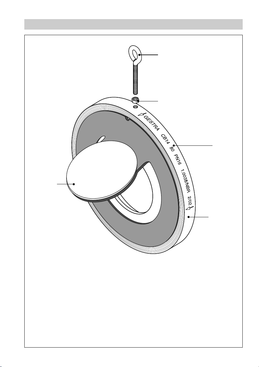
Parts Drawing CB 1...
G
A
B
D
Fig. 1
E
3
Page 4
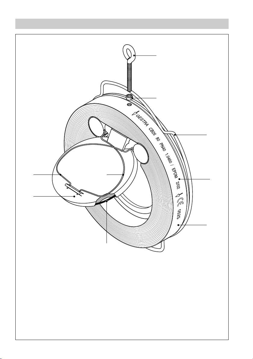
Parts Drawing CB 2...
A
B
C
Fig. 2
4
H
G
H
D
E
F
Page 5

Key
Eye bolt
A
Lock nut
B
Centering ring
C
Type designation (on name plate or impressed on valve body)
D
Body
E
O-ring
F
Disc
G
Spring
H
5
Page 6
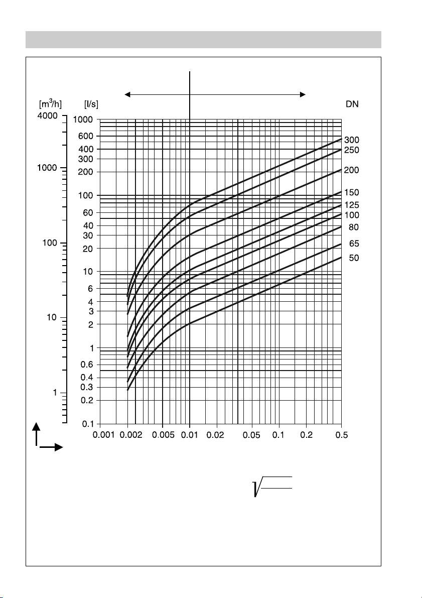
Pressure Drop Chart CB 1...
Partial opening
= instable range
Full opening
= stable range
Fig. 3
6
w
˙
Volume flow V
Pressure drop ∆p [bar]
The curves given in the chart are valid for
water at 20 °C. To read the pressure drop for
other fluids the equivalent water volume
flowrate must be calculated and used in the
graph.
The values indicated in the chart are applicable
to valves with horizontal flow. With vertical
flow insignificant deviations occur only within
the range of partial opening.
˙
V
= V˙ ·
w
˙
V
= Equivalent water volume flow
w
ρ
1000
in [l/s] or [m³/h]
ρ = Density of fluid (operating condition)
in kg/m³
˙
V
= Volume of fluid (operating condition)
w
in [l/s] or [m³/h]
Page 7
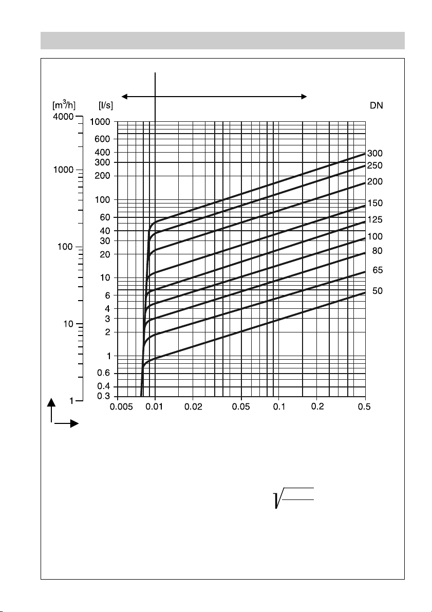
Pressure Drop Chart CB 2...
Partial opening
= instable range
w
˙
Full opening
= stable range
Volume flow V
Pressure drop ∆p [bar]
Fig. 4
The curves given in the chart are valid for
water at 20 °C. To read the pressure drop for
other fluids the equivalent water volume
flowrate must be calculated and used in the
graph.
The values indicated in the chart are applicable
to valves with horizontal flow. With vertical
flow insignificant deviations occur only within
the range of partial opening.
˙
V
= V˙ ·
w
˙
V
= Equivalent water volume flow
w
ρ
1000
in [l/s] or [m³/h]
ρ = Density of fluid (operating condition)
in kg/m³
˙
V
= Volume of fluid (operating condition)
w
in [l/s] or [m³/h]
7
Page 8

Important Notes
Usage for the intended purpose
The swing flap non-return valves CB 1.../CB 2... ensure unidirectional flow in pipes by preventing a
backflow of liquids or gases.
Use this equipment only within the specified pressure and temperature ratings and check corrosion
resistance and chemical suitability for the application in question.
Safety note
The valve must only be installed by qualified staff.
Qualified staff are those persons who - through adequate training in engineering, the use and
application of safety equipment in accordance with regulations concerning safety systems, and first aid
& accident prevention - have achieved a recognised level of competence appropriate to the installation
and commissioning of this device.
Danger
The valve is under pressure during operation.
When loosening flanged connections or sealing plugs, hot water, steam, corrosive liquids
or toxic gases may escape. This presents the danger of severe burns and scalds to the
whole body or severe cases of poisoning.
Installation and maintenance work should only be carried out when the system is
depressurized.
The valve becomes hot or extremely cold during operation. This presents the risk of
severe burns to hands and arms. Installation and maintenance work should only be
carried out at room temperatures.
Sharp edges on internals present a danger of cuts to hands. Always wear industrial
gloves for installation and maintenance work.
8
Page 9

Important Notes – continued –
Ratings pursuant to article 9 of the PED1)
Fluid group
Use
CB 14
CB 24 S
CB 26
CB 26 A
Category IIIIIIIV
Nominal size DN DN DN DN DN
CB 14 50–80 100–200 250–300
CB 24 S 50–80 100–200 250– 300
CB 26 50–100 125–300
CB 26 A 50–100 125–300
CE marking no yes yes yes no
1
) PED = Pressure Equipment Directive
Gas Liquid
1212
no yes no yes
yes yes yes yes
Exception
pursuant to
article 3.3
9
Page 10

Explanatory Notes
Scope of supply
CB 14
1 Swing flap non-return valve CB 14
1 Installation manual
CB 24 S
1 Swing flap non-return valve CB 24 S
1 Installation manual
CB 26
1 Swing flap non-return valve CB 26
1 Installation manual
CB 26 A
1 Swing flap non-return valve CB 26 A
1 Installation manual
Description
The CB 1.../CB 2... are very compact swing flap non-return valves used to prevent the backflow of
fluids. The flap opens and closes automatically as a function of the direction of flow, thus ensuring
unidirectional flow of the fluid. The opening pressure and closing time can be matched to the
application in question by adjusting the spring characteristic. However, this does not apply to CB 14
since this valve is not fitted with a spring. Installation in horizontal or vertical upward flow lines, with
due regard to our installation recommendations.
The CB 1.../CB 2... are equipped with an eyebolt for ease of installation and transport.
Please note that dual-plate check valves should not be used on reciprocating compressor, piston
pumps or where pulsating flow exists.
Function
As the pressure and volume flow rise, the opening angle of the flap increases symmetrically. If
centrifugal pumps are installed upstream of the valve it becomes necessary to arrange for a defined
stabilizing section. Installation in horizontal or vertical upward flow lines, with due regard to our
installation recommendations.
Please observe our installation recommendations outlined in the following pages.
10
Page 11

Explanatory Notes – continued –
Technical Data
Pressure/Temperature Ratings*) CB 14, steel down to –10°C at nominal pressure
DN 50– 300
Temperature [°C] 20 40 60 80 PN
Max. service
pressure
*) When used for its intended purpose.
Pressure/Temperature Ratings*) CB 24 S, bronze down to –200 °C
at nominal pressure
DN 50– 300
Temperature [°C] 20 100 150 200 250 PN
Max. service
pressure
*) When used for its intended purpose. With springs made of bronze up to max. 90 °C.
Pressure/Temperature Ratings*) CB 26, steel down to –10°C at nominal pressure
DN 50– 200
Temperature [°C] 20 100 150 200 250 300 350 PN
Pressure DN 50–200 [bar]
Pressure DN 250–300 [bar]
*) When used for its intended purpose.
Use CB... without springs for temperatures above 300 °C.
Pressure/Temperature Ratings*) CB 26 A, stainless steel down to –10 °C
at nominal pressure
DN 50– 300
Temperature [°C] 20 100 150 200 250 300 350 400 450 PN
Max. service
pressure
*) When used for its intended purpose.
Use CB... without springs for temperatures above 300 °C.
[bar] 16 10 6 4 6–16
[bar] 16 16 16 14 13 6–16
40 38 34 30 27 24 20 6–40
40 32 29 27 24 21 6–40
[bar] 40 38 35 32 30 29 28 27 26 6–40
Corrosion Resistance
If the unit is used for the intended purpose, its safety is not impaired by corrosion.
Sizing
The valve body must not be subjected to pulsating loads. Welds and flanges of the valve are designed
to withstand dynamic loading (bending and alternative stress).
The dimensional allowances for corrosion reflect the latest state of technology.
11
Page 12

Explanatory Notes – continued –
Name Plate / Marking
Direction of flow
Specification impressed on valve body: CB 14, DN 50-80 to EN 19
Size Nominal pressure Material
Fig. 5
Specification impressed on valve body: CB 14, DN 100-200 to EN 19
Fig. 6
Specification (plate): CB 14, DN 250-300 to EN 19
Fig. 7
Specification (plate): CB 24 S, DN 50-80 to EN 19
Fig. 8
Specification (plate): CB 24 S, DN 100-200 to EN 19
Fig. 9
Manufacturing year
(e. g. “02” = 2002)
Specification (plate): CB 26, DN 50-200 to EN 19
Fig. 10
Specification (plate): CB 26 A, DN 50-200 to EN 19
Fig. 11
Specification (plate): CB 24 S, CB 26, CB 26 A, DN 250-300 to EN 19
Fig. 12
12
Page 13

Installation
Note
When the volume flow reaches the instable range (see Pressure Drop Chart) during
operation clatter may occur which gives rise to wear on the oscillating flap. Fig. 3, Fig. 4
Do not install swing flap non-return valves in vertical downward flow lines.
CB 1..., CB 2...
1. Observe installation instructions on page 14.
2. Clean seating surfaces.
3. Installation in horizontal lines: Insert bolts through lower flange holes, fasten nuts. Insert off-the-
shelf seals.
4. Install and align swing flap non-return valve CB.... Make sure that eyebolt
and tighten them evenly.
5. Installation in vertical lines: Insert off-the-shelf seal (bottom).
6. Install and align swing flap non-return valve CB... Insert off-the-shelf seal (top). Insert bolts and
tighten them evenly.
A is on top. Insert bolts
13
Page 14

Installation – continued –
incorrect correct
Fig. 13
Fig. 14
optimum with pump
Fig. 15
14
Fig. 16
Page 15

Commissioning
CB 1..., CB 2...
Swing flap non-return valves do not require any special preparation prior to commissioning.
Unfavourably or incorrectly positioned swing flap non-return valves will lead to loud clattering of the
oscillating flap.
In case of clattering increase pump capacity. Please observe the installation instructions on page 14.
Operation
CB 1..., CB 2...
Unfavourably or incorrectly positioned swing flap non-return valves will lead to loud clattering of the
oscillating flap.
In case of clattering increase pump capacity. Please observe the installation instructions on page 14.
Maintenance
CB 1...
GESTRA Swing flap non-return valves CB 1... do not require special maintenance.
The swing flap non-return valves have to be replaced in case of damage or considerable wear. Parts
subject to wear and spare parts are not available.
15
Page 16

Maintenance – continued –
GESTRA Swing flap non-return valves CB 2... do not require special maintenance.
However, in certain cases it may be necessary to replace the springs or O-rings.
Danger
Note that springs are preloaded which means that they can jump out of the valve body
when the valve is being installed or removed.
This presents the risk of injuries to hands, arms and face.
CB 2... Replace springs / O-ring
1 2
Swing flap non-return valve CB 2...
3 4
Remove springs and O-rings (if fitted).
Insert new O-ring.
16
Detach springs from support.
Insert new springs into the lateral guide.
Page 17

Maintenance – continued –
CB 2... Replace springs / O-ring – continued –
5 6
Insert left and right spring into the support. Check smooth operation of the flap. Install swing flap
Tools
■
Combination pliers 180 mm, DIN 5244
■
Aligning punch, 80 mm
non-return valve in line.
17
Page 18

Spare Parts
Spare Parts List CB 24 S
Item
F
H
Stock code
DN
50 039276 037556 038624 038626
65 031443 033910 038633 038635
80 031753 033911 038642 038644
100 031493 033912 038651 038654
125 031769 033913 038662 038665
150 031525 033914 038673 038675
200 031540 033915 038683 038686
250 039283 033916 038694 038697
300 031573 033917 038705 038708
O-ring EPDM
O-ring FPM
Stock codeStock code
O-ring NBR
Stock code
Spring
Two springs are required per valve. Contact your local dealer for small quantities.
No spare parts available for CB 14.
18
Page 19

Spare Parts – continued –
Spare Parts List CB 26, CB 26A
Item
F
H
Stock code
DN
50 039276 037556 175843 039294
65 031443 033910 703368 039295
80 031753 033911 173844 039296
100 031493 033912 175839 039297
125 031769 033913 703369 039298
150 031525 033914 175841 039299
200 031540 033915 177839 039300
250 039283 033916 174450 039301
300 031573 033917 175131 039302
O-ring EPDM
O-ring FPM
Stock codeStock code
O-ring NBR
Stock code
Spring
Two springs are required per valve. Contact your local dealer for small quantities.
No spare parts available for CB 14.
19
Page 20

Annex
Declaration of Conformity
We hereby declare that the pressure equipment CB 1... and CB 2... conform to the following European
Directive:
■ EC Pressure Equipment Directive (PED) No. 97/23 of 29 May 1997
Swing flap non-return valves are pressure equipment as defined in article 1, section 2.1.4 of the PED.
Applied conformity assessment procedure as described in Annex III for CB 24 and
CB 24 S: Module A1
Applied conformity assessment procedure as described in Annex III for CB 26 and
CB 26 A: Module H - verified by the Notified Body (Registration No.0525).
This declaration is no longer valid if modifications are made to the equipment without consultation
with us.
Bremen, 15th April 2002
GESTRA GmbH
Head of the Design Dept.
Uwe Bledschun
Academically qualified engineer
Quality Assurance Representative
Lars Bohl
20
Page 21

For your notes
21
Page 22

For your notes
22
Page 23

For your notes
23
Page 24

Agencies all over the world
www.gestra.de
GESTRA
España
GESTRA ESPAÑOLA S.A.
Luis Cabrera, 86-88
E-28002 Madrid
Tel. 00 3491 /51 52 032
Fax 00 34 91/ 41 36 747; 51 52 036
E-mail: aromero@flowserve.com
Great Britain
Flowserve Flow Control (UK) Ltd.
Burrel Road, Haywards Heath
West Sussex RH 16 1TL
Tel. 00 44 14 44 / 31 44 00
Fax 00 44 14 44 / 31 45 57
E-mail: gestraukinfo@flowserve.com
Italia
Flowserve S.p.A.
Flow Control Division
Via Prealpi, 30
l-20032 Cormano (MI)
Tel. 00 39 02/ 66 32 51
Fax 00 39 02/66 32 55 60
E-mail: infoitaly@flowserve.com
Poland
GESTRA POLONIA Spolka z.o.o.
Ul. Schuberta 104
PL - 80-172 Gdansk
Tel. 00 48 58 /306 10 -02 od 10
Fax 00 48 58 /306 33 00
E-mail: gestra@gestra.pl
Portugal
Flowserve Portuguesa, Lda.
Av. Dr. Antunes Guimarães, 1159
Porto 4100-082
Tel. 0035122/6198770
Fax 0035122/6107575
E-mail: jtavares@flowserve.com
USA
Flowserve DALCO Steam Products
2601 Grassland Drive
Louisville, KY 40299
Tel.: 00 15 02 / 4 95 01 54, 4 95 17 88
Fax: 00 15 02 / 4 95 16 08
E-Mail: dgoodwin@flowserve.com
GESTRA AG
Postfach 10 54 60, D-28054 Bremen
Münchener Str. 77, D-28215 Bremen
Telefon +49 (0) 421 35 03- 0
Telefax +49 (0) 421 35 03 - 393
E-Mail gestra.ag@flowserve.com
Internet www.gestra.de
810707-02/604cm · © 2001 GESTRA AG · Bremen · Printed in Germany
24
 Loading...