

Page 1
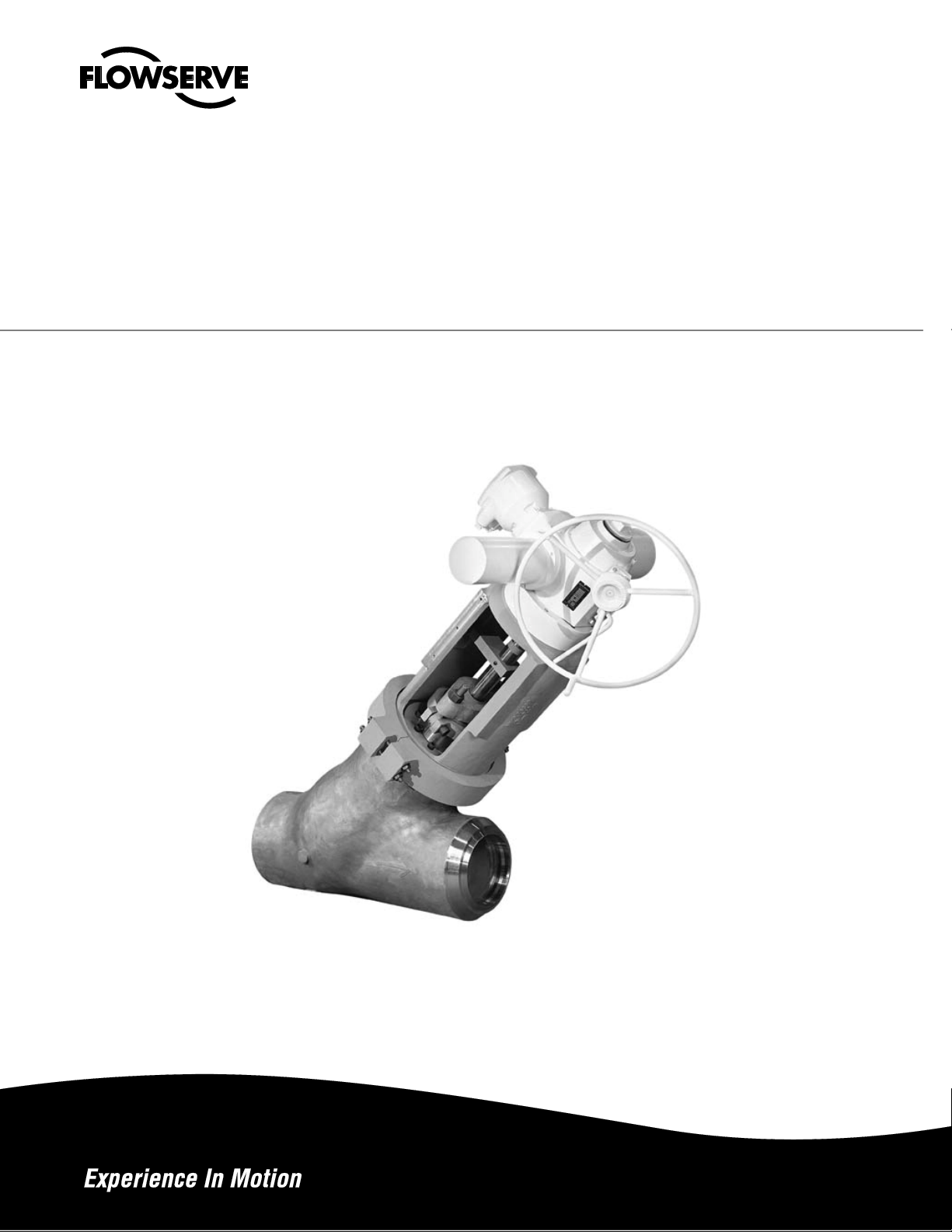
INSTRUCTION MANUAL
G
Anchor Darling Cast
Sizes 2-1/2” through 24”
FCD ADENIM0011-00
lobe Valves
Installation
Operation
Maintenance
Page 2

Table of Contents
1.0
VALVE DESCRIPTION Page
1.1 Recommended Uses..................................................6
1.2 Principles of Operation...............................................6
1.3 Design Features ......................................................7
1.3.1 Bodies ......................................................7
1.3.1 Bonnet Seals ...............................................8
1.3.2 Disc Assembly and Seats............................9
1.3.3 Actuation......................................................9
2.0
CARE OF VALVE PRIOR TO INSTALLATION
2.1 Receiving Inspection................................................10
Globe Valves FCD ADENIM0011-00
2.2 Handling ................................................................ 10
2.3 Storage ................................................................10
3.0
INSTALLATION INSTRUCTIONS
3.1 Rigging ................................................................... 11
3.2 Cleaning ...................................................................11
3.3 Installing Valve In Line .............................................11
4.0
OPERATING THE VALVE
4.1 Hand Actuated .......................................................12
4.2 Motor Actuated .......................................................12
4.3 Throttling .......................................................12
4.4 Isolating .......................................................12
4.5 Operating Tips ........................................................13
5.0
VALVE MAINTENANCE
5.1 Inspection.................................................................14
5.2 Lubrication ...............................................................14
5.3 Cleaning ...................................................................14
5.4 Packing ...................................................................15
5.5 Bolting Torque Values..............................................16
5.6 Refinishing Sealing Surfaces ...................................17
2
Page 3

Table of Contents
(continued)
6.0
DISASSEMBLY Page
6.1 Actuator Removal.....................................................17
6.1.1 Handwheel.................................................18
6.1.2 Gear...........................................................19
6.1.3 Electric Motor.............................................20
6.2 Flanged Bonnet Valves............................................20
6.2.1 Packing ....................................................20
6.2.2 Yoke ....................................................21
6.2.3 Bonnet ....................................................22
6.2.4 Disc and Stem ...........................................23
6.3 Pressure Seal Bonnet Valves ..................................24
Globe Valves FCD ADENIM0011-00
6.3.1 Yoke ....................................................24
6.3.2 Bonnet ....................................................25
6.3.3 Disc and Stem ...........................................29
7.0
ASSEMBLY
7.1 Flanged Bonnet Valves............................................30
7.1.1 Disc and Stem............................................30
7.1.2 Bonnet........................................................30
7.1.3 Yoke...........................................................31
7.2 Pressure Seal Bonnet Valves ..................................31
7.2.1 Disc and Stem............................................31
7.2.2 Bonnet........................................................31
7.2.3 Yoke...........................................................32
7.3 Actuators..................................................................32
7.3.1 Manual Actuators.......................................32
7.3.2 Air Cylinder and Motor...............................32
3
Page 4

Revision Sheet
Revision Date Changes Description
- 9/19/2005 Original Issue
Globe Valves FCD ADENIM0011-00
4
Page 5
Globe Valves FCD ADENIM0011-00
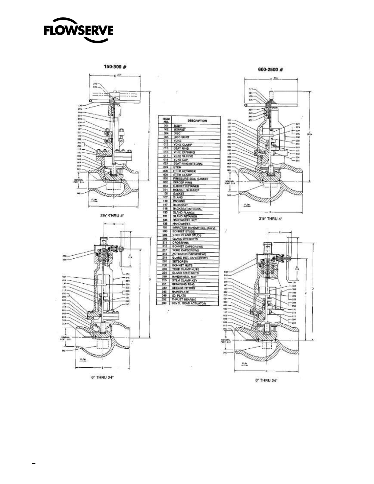
Globe Valve Designs
5
Page 6
Globe Valves FCD ADENIM0011-00
1.0 VALVE DESCRIPTION
1.1 Recommended Uses
Anchor/Darling Globe valves are designed primarily to regulate the volume of flow within a piping system. With the
appropriate disc (for the service) installed, they will throttle fluids with minimal erosion and cavitation. By taking certain
precautions they may also be used for isolation purposes.
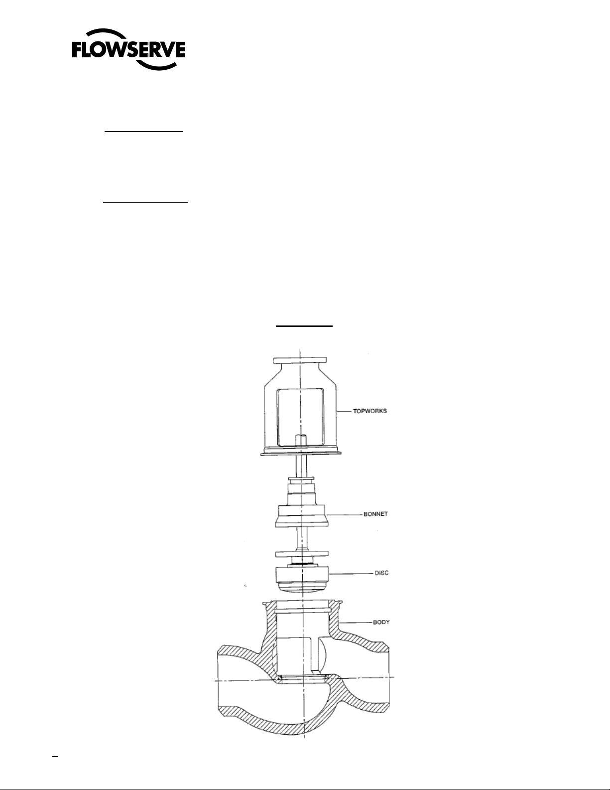
1.2 Principles of Operation
The principle parts of a globe valve are the body, bonnet, disc and topworks (Fig. 1). The body and bonnet contain the
fluid within the system. The disc is positioned by the stem in the flow path above the seat. Movement of the stem (in line
with the flow) increases or decreases the annular area between the disc and seat, metering the volume of fluid that
passes between them. When used for isolation purposes the disc to seat seal is created by either a mechanical or an
internal pressure force. When installed with flow under the disc, the stem and topworks provide a mechanical thrust that
holds the disc into the seat against the fluid pressure. With flow over the disc, the differential pressure itself forces the
disc into the seat. The latter situation with the line pressure working towards the seal rather than against it, provides for
more reliable isolation.
FIGURE 1
6
Page 7
Globe Valves FCD ADENIM0011-00
1.0 VALVE DESCRIPTION
1.3 Design Features
1.3.1 Bodies
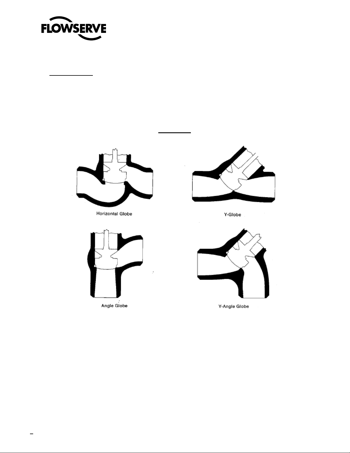
Anchor/Darling Globe valves are supplied in four different body styles (Fig. 2). Regular (or Horizontal) Pattern, Y
Pattern, Angle Pattern and Elbow Down (or Y-Angle) Pattern. While all the bodies incorporate the same operating
principles their various configuration allow them to be installed in a variety of piping configurations
(Continued)
FIGURE 2
7
Page 8
Globe Valves FCD ADENIM0011-00
1.0 VALVE DESCRIPTION
1.3 Design Features (Continued)
1.3.2 Bonnet Seals
Anchor/Darling Globe valves are supplied with two basic types of bodybonnet closures: bolted bonnet or pressure
seal. The bolted bonnet closure (Fig. 3) is a bolted flange tongue and groove joint with spiral-wound stainless
steel gasket and asbestos filler. The seal depends upon the bolt preload to maintain sufficient compressive force
on the gasket.
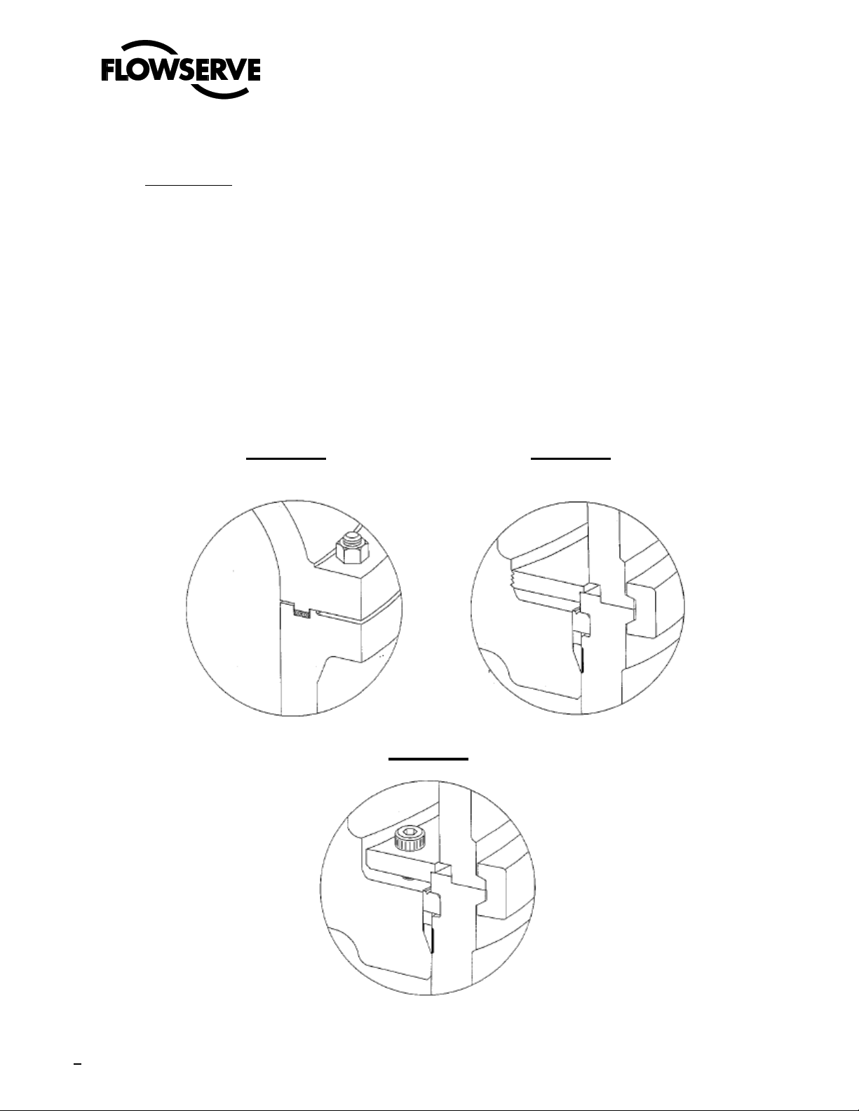
Pressure seal type closures (Figs. 4 & 5) utilize a tapered soft metal ring gasket for sealing. The gasket is
contained within the body neck bore by a retaining ring. The tapered inner surface of the gasket bears against a
mating annular surface on the valve bonnet. Under internal pressure, the bonnet is forced against the pressure
seal gasket, wedging it against the body neck wall. A slight interference angle produces a line contact and high
sealing pressure. The greater the valve pressure the tighter the metal-ta-metal seal. No bolting is required to
maintain the seal although the bonnet is initially drawn into contact with the pressure seal by cap screws.
(Continued)
FIGURE 3 FIGURE 4
FIGURE 5
8
Page 9
Globe Valves FCD ADENIM0011-00
1.0 VALVE DESCRIPTION
1.3 Design Features (Continued)
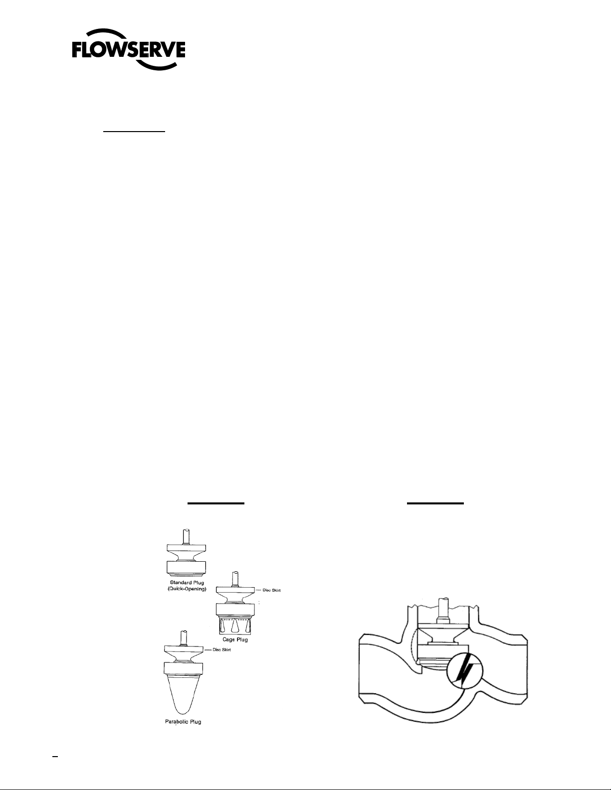
1.3.3 Discs and Seat
Anchor/Darling Globe valves are supplied with a wide variety of discs to handle various throttling requirements. All
of the discs, however, are variations of three basic types (Fig. 6)
Quick Opening - for moderate throttling
Cage - for more severe throttling
Parabolic - for linear flow control
Anchor/Darling Globe valve discs incorporate a disc skirt to prevent cocking and to ensure proper disc/seat
alignment regardless of installation orientation. The globe valve main seat consists of a hard surfaced ring set into
a recess in the body which supports and retains it. A seal weld is provided between the body and the rings. This
weld is for sealing only and serves no structural purpose. The seat ring is replaceable.
There is a 1 degree difference in the angle on the disc and seat sealing surfaces (fig. 7). This design provides for
line contact at the seal and tight sealing at low force.
1.3.4 Valve Actuation
A globe valve is operated by moving the disc in and out of the seat with the stem. The necessary thrust for
opening or closing is imparted to the stem by the valve actuator which is supported and restrained by the yoke
structure. Five types of actuators are normally supplied: handwheel, manual gear, electric motor, pneumatic
cylinder and hydraulic cylinder. The first three impart rotary motion to a stem nut which converts the rotary motion
to linear stem movement via the ACME stem threads. The pneumatic and hydraulic cylinder actuators provide
direct linear motion to the stem.
Sealing of the bonnet stem penetration is accomplished by a bolted gland stuffing box containing ring-type
packing.
(Continued)
FIGURE 6 FIGURE 7
9
Page 10

Globe Valves FCD ADENIM0011-00
2.0 CARE OF VALVE PRIOR TO INSTALLATION
2.1 Receiving Inspection
Upon receipt of the valve, thoroughly inspect it for shipping damage. As a minimum, the following items should be
checked:
1. Handwheel and shaft-check for bending or impact damage.
2. Switches and actuating mechanisms bent or broken parts?
3. Missing or loose bolting?
4. End covers in place?
5. Is valve securely fastened to shipping skid?
6. Abrasion-damaged paint?
7. Are spare parts shipped with valve in place and secure?
2.2 Handling
2.3 Storage
Store valves on their shipping skids in a clean dry area protected from weather. Anchor/Darling valves are shipped
Anchor/Darling valves are shipped strapped to wooden skids designed to be moved by forklift. It is recommended that
when being handled prior to installation, the valve be kept on its skid and a forklift truck be used for moving. If an
overhead crane is used, care must be exercised to center the load. The slings should not lift the valve by the wooden skid
structure alone, but must pass under the valve.
without the permanent packing installed. Experience indicates that stem corrosion pitting can result when valves are
stored with the packing in place. For this reason we do not recommend installing the packing until valve is to be put in
service. The service packing is shipped with the valve, contained in a plastic bag placed in the valve port or attached to
the yoke. lithe packing is removed for storage elsewhere, reseal the valve end covers to protect the internal cleanliness of
the valve. Motor actuated valves, if stored for more than a few months require special care of the operator. Motor and
switch compartment heaters, if supplied, should be connected. The major concern is condensation on the internal parts
of the actuator. For this reason, rapid and/or extreme temperature and humidity changes should be avoided. Storage in a
temperature and humidity controlled environment is desirable. Long term storage of motor actuators may affect the terms
of the warranty and the actuator manufacturer should be contacted for specific information.
10
Page 11

Globe Valves FCD ADENIM0011-00
3.0 INSTALLATION INSTRUCTIONS
3.1 Rigging
3.2 Cleaning
Prior to installation remove the valve end covers and inspect for cleanliness. If any sign of foreign matter is observed in
3.3 Installing Valve In Line
3.3.1 The pipe must be properly supported and aligned with the valve. Seat leakage in valves is frequently caused by
seat misalignment resulting from excessive end moments introduced in the cold springing of the connecting pipe.
3.3.2 Before welding valves with weld ends into the line, raise the disc off the seat a sufficient distance to prevent arcing.
3.3.3 Extreme care must be taken to insure that globe valves are installed with the flow arrow in the proper direction.
3.3.4 While valves used for isolation may be installed with flow in either direction, a more reliable seal will be provided if
3.3.5 It is recommended that globe valves be installed with the stem vertical. This orientation provides enhanced
3.3.6 Globe 'stop check valves must be installed with the stem vertical. Installation in any other orientation will not
3.3.7 Following installation of the valve in the line, install the packing supplied with the valve. (See the maintenance
3.3.8 Before the valve is placed in operation, check all bolting for tightness and lubrication per section 5.5.
When lifting the valve for installation in the line, it is important that slings of adequate size are used. The capacity of the
sling must exceed the weight of the valve with its actuator. Slings should pass under the valve body and through the
yoke arms. Block care fully to prevent damage or abrasion of components and finishes.
the valve internals, open the valve and place it on its side-(stem horizontal) and flush thoroughly with water. Steam or air
may be used if water is net available but exercise caution that the high velocity does not drive debris into clearance
spaces.
When used for throttling, globe valves supplied with quick opening and parabolic discs must be installed with flow
from under the disc. When supplied with a cage disc the valve must be installed with flow from over the disc.
Failure to install valves used for throttling with the flow in the proper direction can cause damaging cavitation and
erosion of critical surfaces.
the flow is from over the disc.
packing life and simplifies disassembly & reassembly.
provide automatic reverse flow protection.
section 5.4 for specific instructions). This operation may be performed following valve cleaning if more convenient.
11
Page 12

Globe Valves FCD ADENIM0011-00
4.0 OPERATING THE VALVE
Prior to operating the valve for the first time, verify that the valve has been prepared in accordance with the preceding sections
of this manual.
4.1 Hand Actuated
Handwheel actuated valves close on clockwise rotation of the wheel and open counter-clockwise. This is true also for the
handwheel on gear and motor actuators.
4.2 Motor Actuated
4.2.1 The motor actuators on Anchor/Darling valves are adjusted for correct operation when shipped from our plant. It
should not be necessary to re-adjust the torque and limit switches when the valve is placed in operation unless the
actuator has been removed from the valve or the switch adjustments have been tampered with.
4.2.2 Adjustments of torque or limit switches should not be attempted without first consulting Anchor/Darling Service
Engineers. Failure to obtain proper authorization when resetting torque or limit switches may void the warranty.
Under no circumstances should the torque and/or limit switches be completely bypassed. They are included to
provide protection of the valve internals. Removal of their protection can cause extensive damage to the
equipment.
4.2.3 The valve is normally supplied with the torque switch wired to stop the operator in the closed position and the limit
switch wired to stop in the full open position. Using the torque switch to control travel in the opening direction may
damage the backseat. The valve should be backseated only by using the handwheel.
4.2.4 When powering the actuator for the first time observe that the direction of rotation is correct. If not, the power leads
must be reversed.
4.2.5 Manual operation may be performed at any time by pulling the declutch lever downward. The lever will stay in the
manual mode until the electric motor is actuated whereupon it will automatically disengage.
4.3 Throttling
Changing the position of the disc will vary the volume of fluid allowed to pass through the seat. Once the desired flow rate
is obtained the valve can be left unattended. Selflocking stem threads insure that the disc position will be maintained.
4.4 Isolating
When valves are closed and flow is over the disc, shut off should be obtained and maintained without adjustment. When
valves are closed with flow under the disc, sufficient force must be extended on handwheel or by the motor in order to
achieve a seal. If the valve is supplied with an impactor handwheel it may be necessary to use the impactor to get tight
shutoff. In addition, globe valves, shut off with flow under the disc, should be periodically checked to see that they are
sealing properly. If leakage is present, additional force must be applied to the stem to reseal the disc. With the disc in
the closed position the seat must not be allowed to leak for an extended period of time. Continuous seat leakage may
cause severe damage to the sealing surface.
12
Page 13

Globe Valves FCD ADENIM0011-00
4.0 OPERATING THE VALVE
4.5 Operating Tips
Do:
- Operate valves at least every 6 months.
- Keep stem clean and lubricated.
- Inspect valves regularly.
- Lap seats promptly if valve leaks.
- Use normal torque on handwheel.
- Check packing regularly.
Do Not:
- Overtighten packing.
- Torque-out motor operator against backseat.
- Keep valve backseated during normal operation.
- Bypass or reset torque or limit switches.
- Use unauthorized actuator assists such as – pipe wrenches – cheaters.
- Bring valve to fully backseated position immediately upon opening a valve
in a hot system. Allow 15 minutes for stem to cool before backseating
valve.
(Continued)
13
Page 14

Globe Valves FCD ADENIM0011-00
5.0 VALVE MAINTENANCE
Anchor/Darling Valves are designed to be essentially maintenance free pieces of equipment. When-used in the proper
application and operated correctly, they will provide reliable operation for many years. The only area that is expected to
require regular attention is the adjustment and (if necessary) replacement of the stem packing. The frequency of this
operation will be dependent on the service conditions, the type of packing used and the care with which it is installed. Some
other maintenance recommendations are included in the following sections for information.
5.1 Inspection
The most important aspect of valve maintenance is periodic inspection. The early detection of a malfunction can, in
many cases, prevent a minor defect from becoming a major problem. It is very important that leakage from any of the
major seals (packing, disc/seat, body-bonnet) be addressed immediately. The smallest weepage can quickly
become a major problem if it is not treated promptly. Some other areas that should be included in a periodic
inspection program are:
1. Lubrication: - Stem
- Yoke Sleeve
- Motor Actuator Drive Sleeve
- Pneumatic Actuator Sliding Surfaces
2. Cleaning: - Stem
- Packing Area
- Pressure Seal Area
- Body Bonnet Studs
3. Bolting: - Body-Bonnet
- Bonnet Yoke
- Motor Actuator
4. Packing Adjustment
5.2 Lubrication
1. Stem: Keep stem threads lubricated with a light coating of grease (NLG1 No.2 or equal).
2. Yoke Sleeve: Lubricate with general purpose grease every six-months. Apply with grease gun to grease-fitting
(Item 340).
3. Air cylinder operated-valves require only a light coating of grease or oil on the stanchions.
4. Motor Actuator: Every six months lubricate drive sleeve top bearing, using grease gun on pressure fitting in
housing cover. See Motor Actuator Manual for further information.
5.3 Cleaning
The frequency and extent of cleaning will depend on the valves' location and service conditions. It is important
that the stem and packing gland parts be kept clean and free of foreign material. Do not allow water or dirt to
collect in the body neck bore area above the pressure seal of pressure seal valves. The build-Up of corrosion or
extraneous material may interfere with removal of the bonnet. For the same reason excessive rust should not
be allowed to build-up QD the body-bonnet bolting of bolted bonnet valves.
14
Page 15

5.0 VALVE MAINTENANCE
5.4 Packing
Anchor/Darling Globe valves are supplied with John Crane 187-1 packing unless otherwise specified. When specially
ordered, valves are supplied with Graphoil packing which requires more specialized care in installation. The packing
manufacturers' instructions should be followed. The following packing installation procedures are for John Crane
187-1 or similar packing.
1. Unbolt gland bolts and raise gland flange and gland. These two parts may be held out of the way with wire or
twine. To prevent the loss of the two gland nuts, thread back on the gland bolts.
2. If the valve is being repacked, remove the old packing with a packing hook. The lantern ring in double packed
valves should also be removed with the packing hook, utilizing the holes drilled in the top of the lantern ring, which, in
the case of larger valves, are threaded. This feature permits the use of threaded rods for removal in difficult cases.
During these operations take care not to scratch the stem.
3. After the old packing is removed, inspect the stuffing box for cleanliness. Blowout with compressed air if available.
4. Install new rings one at a time. Be careful that the cut ends of the rings butt together and do not overlap. This is
particularly important when packing is cut from roll stock. Install the rings with the butt joints offset 180' from each
other. Do not use a pointed instrument to push the rings into position. A packing iron should be used for this purpose
(Fig. 8). The ability of packing to seal the stem is dependent on the amount of loading that each individual ring
receives. It is particularly important for the bottom rings in the stuffing box to be forced tightly into place. This is most
easily accomplished by ramming the rings into place with the packing iron. When packing double packing boxes with
leak-off it is essential that sufficient rings of lower packing be installed to position the lantern ring at the level of the
leak-off. When the stuffing box is full, tighten the gland nuts evenly to ensure that the gland is concentric with the
stem. Cocking of the gland or gland flange can cause binding and scoring of the stem.
5. Operate the valve once to verify that the packing is not too tight and binding the stem.
6. After the valve has been in operation a few days, retighten the packing nuts to compensate for compression of the
packing. At this time, if there is room, it is advisable to add another ring of packing.
7. Remove stem from backseated position so that packing does not dry out.
Globe Valves FCD ADENIM0011-00
(Continued)
FIGURE 8
PACKING IRON
15
Page 16

Globe Valves FCD ADENIM0011-00
16
5.0 VALVE MAINTENANCE
5.5 Bolting Torque Values
At regular intervals not-more than six-months, check the tightness of all bolting. Bolted bonnet valves should have
the body-bonnet bolting torqued to the values shown in Table 1.
1. Torque values specified on certified assembly drawings always superseded this manual.
2. The maximum torque values are provided for guidance in field work where higher torques may be required
because of material conditions such as rust and oxides.
The following torque values are provided for guidance in field work. The torque values provided for design were developed using an
assumed friction coefficient of 0.2. These maximum torque valves provide for a range of friction coefficients without damage to the
designated bolting material.
A193 A193 A564 A453 A574
STUD SIZE B7 - B16 B8 &B8M 630-1100 660
5/16 - 18 11 6.5 13 12 15
3/8 - 16 20 12 23 20 26
7/16 -14 30 19 36 30 44
1/2 - 13 45 28 55 50 67
9/16 -12 70 40 80 70 -
5/8 - 11 90 56 110 100 130
3/4 - 10 165 100 195 165 230
7/8 - 9 270 160 310 280 375
1 - 8 400 240 470 420 560
1 1/8 - 8 600 350 690 600 800
1 ¼ - 8 800 500 970 850 1140
1 3/8 - 8 1100 675 1320 1200 1500
1 ½ - 8 1500 900 1750 1600 1970
1 5/8 - 8 1900 1150 2250 2000 -
1 ¾ - 8 2400 1450 2850 2500 3100
1 7/8 - 8 3000 1800 3500 3200 -
2 - 8 3700 2200 4300 3900 4600
2 1/8 - 8 4400 2650 5200 4700 -
2 ¼ - 8 5300 3200 6200 5600 6900
2 ½ - 8 7400 4400 8600 8000 9400
2 ¾ - 8 8700 5900 11600 10400 12800
3 - 8 11400 7800 15200 13000 16900
(Continued)
TABLE 1
BODY - BONNET BOLTING TORQUE (ft-lb)
Maximum
Page 17

17
Globe Valves FCD ADENIM0011-00
5.0 VALVE MAINTENANCE
5.6 Refinishing Sealing Surfaces
Minor discontinuities in both the disc and seat sealing surfaces, which may cause leakage, can, in many cases, be
removed by lapping. Major defects such as cracks or deep gouges will generally require replacement of the part.
NOTE: Lapping is a polishing process in which a sealing surface is ground with an abrasive held in place by a
special fixture. The abrasive is commonly found in paste form or bonded to a paper backing. Detailed
instructions on the use of lapping abrasives and fixtures, normally supplied with such equipment, should be
adhered to.
In order to maintain seat tightness in globe valves, the sealing surface angles on both the disc and seat ring must be
kept within close tolerance (300 for the seat - 290 for the disc) it is important when lapping to use fixtures that will
maintain these angles. Anchor/Darling does not recommend lapping the disc directly to the seat. A good seal is
dependent on line contact. Direct contact lapping will result in excessive seat widths.
(Continued)
6.0 DISASSEMBLY
By carefully following these instructions any Flowserve valve can be easily disassembled and reassembled. If problems are
encountered with equipment, Flowserve Field Service should be contacted. The use of improper tools or methods may cause
severe damage to the valve and may void the warranty.
Prior to attempting disassembly of a particular valve, the specific assembly drawing for the valve should be referred to.
6.1 Actuator Removal
Valves are supplied with a wide variety of actuating mechanisms. The degree of difficulty involved in their removal
varies significantly. Simple bolt-on units such as handwheels, gear units and electric motor units are fairly
commonplace. Their removal only requires the use of good mechanical practice. More complex pneumatic and
hydraulic units may require specialized skills. Their removal and disassembly should only be attempted by trained
personnel. More detailed information on special actuators will be provided in a separate manual when applicable.
The following general guidelines are provided for information:
1. Before any attempt to remove the actuator is made, personnel should verify that the system is
depressurized and drained.
2. The valve should then be cycled partially to remove any trapped pressure and to insure that the disc is not
stuck in the seat.
3. The disc should then be gently lowered into the seat.
4. When the valve is to be completely disassembled, Flowserve recommends that the actuator be removed
from the valve separately from the yoke. This will simplify the rigging requirements.
Page 18

Globe Valves FCD ADENIM0011-00
6.0 DISASSEMBLY
6.1.1 Handwheels
On handwheel actuated valves (Fig. 9) the handwheel can be removed by removing the retaining ring (261)
Note: If desired, the yoke and handwheel assembly may be separated from the valve in one piece. Once
If further disassembly of the handwheel mechanism is required, the yoke cap capscrews (217) and the yoke
(Continued)
and pulling the handwheel (136) off the yoke sleeve (017). Care should be taken not to lose the handwheel
keys (135).
the yoke-bonnet fasteners are removed, the entire assembly can be raised off the stem by turning the
handwheel while the yoke is held stationary.
cap (019) must be removed first. Then the thrust bearing (352) and the yoke sleeve (017) can be lifted out
of the yoke (011).
FIGURE 9
18
Page 19

6.0 DISASSEMBLY
(Continued)
Globe Valves FCD ADENIM0011-00
Two types of gear actuators have been supplied on Anchor/Darling valves. Earlier model valves may have
6.1.2 Gear Actuators
been supplied with gear units manufactured by Anchor/Darling (Fig. 10). This type of unit requires complete
disassembly in order to remove it from the yoke. Specific instructions on disassembly were provided with
the original equipment. Anchor/Darling service engineers can provide duplicates of this information when
provided with the original order or drawing number.
FIGURE 10
FIGURE 11
19
Page 20

Globe Valves FCD ADENIM0011-00
6.0 DISASSEMBLY
6.1.2 Gear Actuators (continued)
6.1.3 Electric Motor Actuators
6.2 Flanged Bonnet Valves
6.2.1 Packing (Fig. 13):
(Continued)
Later model valves (Fig. 11) are supplied with self-contained units that can be separated from the yoke
(011) by removing the actuator capscrews (218). If a stem protector (334) is provided it should be removed.
With the actuator properly supported, it may be raised off the yoke either by turning the handwheel or
rotating the entire unit.
Although various types of electric motor actuators (Fig. 12) are supplied, all follow the same pattern for their
removal from the valve. Prior to removal, all power and control wiring should be disconnected from the
actuator. With the stem protector (334) and capscrews (218) removed, and the actuator properly
supported, it can be raised in the same manner as the gear unit.
Unscrew the gland stud nuts (234), raise the gland flange (130), and gland (107); then pull out the packing.
FIGURE 12
FIGURE 13
20
Page 21

Globe Valves FCD ADENIM0011-00
6.0 DISASSEMBLY
6.2.2 Yoke: (Figs. 13 & 14)
Removal of the yoke will be simplified if the stem clamp (029) has been previously loosened. To loosen the
stem clamp, back out the set screw (220), raise the clamp on the stem and remove the stem clamp key
(255). The key should be set aside in a safe place for reassembly. To remove the yoke (011), unbolt the
capscrews (217) that fasten it to the bonnet (002).
(Continued)
FIGURE 14
21
Page 22

Globe Valves FCD ADENIM0011-00
6.0 DISASSEMBLY
6.2.3 Bonnet: (Fig 15)
Remove the nuts (230) from the bonnet studs (200). If the bonnet is too heavy to lift by hand, utilize a hoist
with choker around the bonnet neck or two eye-bolts in the yoke bolt holes. Lift the bonnet clear of the valve
body and stem. Remove the spiral-wound gasket (100) from its groove. This operation may require the
use of a screwdriver or similar tool to pry the gasket from the groove. Be careful not to scratch the gasket
seating surfaces.
(Continued)
FIGURE 15
22
Page 23

6.0 DISASSEMBLY
6.2.4 Disc & Stem: (Fig. 16)
The disc (004) and stem (025) are lifted out of the Body together utilizing an eye-bolt in the tapped hole
provided at the end of the stem. In order to separate the disc assembly from the stem, the disc skirt (005)
must be unthreaded from the disc. To prevent backing out during operation, the skirt is tack welded to the
disc. When grinding these welds make sure all the bead is removed. Failure to do so may cause damage to
the skirt threads. Once the weld is removed the disc can be unthreaded from the skirt/disc assembly. The
skirt is held on the stem by a retainer (028) that consists of two 1800 ring segments. Access to the retainer
is gained by raising the skirt on the stem whereby the ring halves can be pulled out of the slot in the stem
below the backseat. The skirt can now be slid off the long end of the stem. Care should be taken to prevent
the ring halves from being misplaced.
(Continued)
Globe Valves FCD ADENIM0011-00
FIGURE 16
23
Page 24

Globe Valves FCD ADENIM0011-00
6.0 DISASSEMBLY
6.3 Pressure Seal Bonnet Valves
6.3.1 Yoke: Removal/Installation (Fig. 17)
As with the flanged bonnet valves, the stem clamp should be loosened prior to removing the yoke. Unbolt
the yoke clamp bolting (204 & 233) and remove the yoke clamp (012). (It is advisable to rut the yoke clamp
components back together to prevent losing the parts.) The yoke (011) is now free to be lifted directly from
the valve, if the actuator and yoke sleeve have been removed. If the actuator is in place, thread the yoke
from the stem by turning the handwheel or rotating the yoke. Assembly is the reverse of the above
procedure.
(Continued)
FIGURE 17
24
Page 25

Globe Valves FCD ADENIM0011-00
6.0 DISASSEMBLY
6.3.2 Bonnet: (Figs.18, 19, 20 & 21)
a. Unbolt the gland nuts (234) and remove the gland flange (130) and gland (107). Put them in a safe place
c. Tap the bonnet sharply to break the seal between it and the pressure seal gasket (ll3ll). The bonnet will
d. The retaining ring (gasket) (033) is comprised of four segments, one of which has a small drilled hole.
e. The bonnet is now ready for removal from the body. The tight clearances between the body bonnet and
f. The preferred method of lifting the bonnet (fig. 21) is by using slings attached to the gland retainer (131).
g. Following the above procedure will, in most cases, result in removal of the bonnet with little difficulty.
However, certain circumstances such as installation of the valve with stem in other than a vertical
h. It is not normally recommended that the pressure seal gasket be reused. However, if a spare gasket is
(Continued)
The_ following instructions assume the yoke has been removed as explained in 6.3.
and thread the nuts back on the gland studs to prevent loss. Remove the packing (110).
b. On globe valves 6" and larger the bonnet is-held in the raised position by capscrews (216) that draw it up
against a bonnet retainer (034). To disassemble these bonnets, first remove the capscrews and then lift off
the retainer. On globe valves 4" and smaller, a different arrangement is used. The bonnet retainer is
threaded onto the bonnet neck. It must be unthreaded off the bonnet. (Note: in order to lift the retainer off
the bonnet the gland retaining assembly must first be completely removed.)
drop downward against the stop, uncovering the retaining ring (033).
Remove this piece first. The groove in the top of the retaining ring gasket permits the use of a pry bar or
screwdriver in removing the segments. In some cases, it may be necessary to loosen the segments by
tapping with a hammer or bar.
gasket, necessary far a reliable seal require that the-bonnet be withdrawn squarely from·the neck bore.
The slightest cocking of the bonnet during withdrawal can cause it bind. Therefore, it is recommended prior
to removal that the squareness of the bonnet and gasket with respect to the body be checked. This is most
easily accomplished by measuring the distance between the top of the gasket and top of the body neck. If
the gasket is not square, it should be tapped with a brass rod until it is. With large bonnets it is a good idea,
as well, to periodically check the squareness of bonnet as it is being withdrawn. Binding any time during
withdrawal, indicates the bonnet has cocked. Further efforts to force the bonnet will generally make the
situation worse. At the first sign of binding, stop and check the squareness of the bonnet.
This means of lifting minimizes cocking. In order to attain the best attachment, the gland bolts (209) should
be removed and the retaining rings' halves be reassembled on the bonnet. If desired, the sling can be
looped through the retaining ring ears prior to assembly on the bonnet. Attempting to remove the bonnet by
raising the stem, either with slings or the actuator, is not recommended. The load between the stem and
the bonnet will be imparted to the backseat. Excessive force on the backseat sealing surface will cause it to
deform or crack.
orientation may cause complications. If greater difficulty is encountered, an Anchor/Darling service
engineer should be consulted. Excessive force which may damage critical surfaces should be avoided.
not available, mark the gasket, bonnet and body prior to removal so that the gasket may be reinstalled in its
original orientation.
25
Page 26

Globe Valves FCD ADENIM0011-00
FIGURE 18
26
Page 27

FIGURE 19
Globe Valves FCD ADENIM0011-00
27
Page 28

Thread
ed
Thread
ed
S
pacer
Globe Valves FCD ADENIM0011-00
Bonnet
Retainer
Gasket
Retainer
Ring
FIGURE 20
Pressure Seal
Gasket
Threaded Bonnet
28
Page 29

Globe Valves FCD ADENIM0011-00
FIGURE 21
6.3.3 Disc and Stem Removal/Installation
Removal of the disc and/or stem is the same as for bolted bonnet valves.
29
Page 30

Globe Valves FCD ADENIM0011-00
7.0 ASSEMBLY
Before starting-the reassembly of the valve, all parts should be thoroughly cleaned and inspected. All foreign material should
be removed from any area of the valve. However, there are certain critical areas that must be free of dirt, weld spatter, filing,
etc. These include the following:
1. Disc and seat sealing surfaces
2. Bonnet 00 fen pressure seal valves)
3. Body neck 19 (on pressure seal valves)
4. Gasket tongue (on flanged bonnets)
5. Gasket groove (on flanged bodies)
6. Bonnet studs- and nuts
7, Stem (all)
8. Stuffing box-(ID)
9. Gland (all)
10. Pressure- seat gasket
These ten areas must also be free of any nicks, scratches, gouges, etc. Any damage in these areas must be repaired. Any
questions about the acceptability of any surface condition should be discussed with a service engineer prior to using the part.
7.1 Flanged Bonnet Valves
7.1.1 Disc-Stem Assembly
The first step in the assembly process is to check the disc pack to seat ring clearance and adjust if
necessary.
1. Prior to attaching the disc (004) to the skirt (005), the stem retainers (028) must be installed. The simplest
way to accomplish this is slide the skirt up over the lower end of the stem until the retainer slot in the stem is
exposed. The stem retainer halves can be inserted into the slot. Lowering the skirt on the stem will capture
the ring and hold it in place.
2. The skirt/stem assembly can now be placed over the disc and threaded into it either by rotating the disc
or the skirt. With the skirt fully threaded into the disc, there should still be some flexibility between the disc
and the stem. If the connection is rigid, the skirt should be backed out a quarter turn to provide some
freedom.
3. After proper positioning, the skirt should be tack welded to the disc in three places 120 degrees apart.
7.1.2 Bonnet
Prior to lowering the bonnet (002) into position, a new gasket should be placed in the gasket groove on the
body flange. Carefully insert the stem into the backseat bushing in the bonnet and lower it into position on
the body. In lowering the bonnet be careful that neither the backseat nor the stem are scratched or gouged.
Damage to either of these surfaces can impair their sealing ability. If orientation of the actuator is important,
the bonnet should be rotated to its proper position prior to lowering it onto the gasket. With the bonnet in
place, the studs (200) and nuts (230) can be installed. Prior to installation the studs and nuts should be
cleaned and thoroughly lubricated with a high quality lubricant. Any nuts or studs with damaged threads
should be replaced. It is very important that the body-bonnet bolting be torqued to specific value in
accordance with a specific procedure. The torque valves are shown in Table 1 for various diameter studs.
The nuts should be tightened evenly using a criss-cross pattern similar to the one shown in Fig. 22. Tighten
all of the nuts to 1/3 of the recommended valve initially. Then repeat the sequence raising the torque to 2/3
of the full torque. Finally, torque all the nuts to the recommended value following the criss-cross pattern. It is
essential that the flange faces remain parallel and all the bolting has uniform tension. Failure to achieve
this may cause gasket weepage when the joint is subjected to operating pressures and temperatures.
30
Page 31

Globe Valves FCD ADENIM0011-00
7.0 ASSEMBLY (continued)
7.1.3 Yoke
1. Before installing the yoke, the stem clamp (029) should be lowered onto the stem. It should be left loose
until the yoke is in place.
2. Since access is better before the yoke is in place, it may be advantageous to install the packing at this
time.
3. The yoke (011) can now be lowered over the stem. Once it is properly positioned, the yoke capscrews
(217) can be installed and tightened.
4. The stem clamp can now be raised over the stem and the key; making sure the slotted end is captured
by the guide rib that is cast on inside of the yoke. When in place the set screw should be tightened and
staked.
7.2 Pressure Seal Bonnet Valves
7.2.1 Disc-Stem Assembly
The procedures for assembling the disc to the stem in a pressure seal valve is identical to the one for
flanged bonnet valves included in section 7.1.1. Refer to it for instructions.
7.2.2 Bonnet
Once the stem-disc assembly is in place the bonnet (002) can be inserted into the neck. Care must be
taken in lowering the bonnet on the stem, so that neither the backseat nor any surface of the stem is
damaged. It is again very important to keep the bonnet from cocking as it is lowered into the body. If it
does bind, the bonnet must be straightened before insertion can continue. Measuring the bonnet bolting
surface to the top of body is the simplest way to detect cocking.
With the bonnet sitting in the counterbore in the neck, a new gasket (032) can be inserted. In that the
gasket may also cock, it must be installed with care. Once these are in place, it is important to remember
that the piece with the drilled hole must be positioned last. If the valve is installed in other than the stemvertical position, it may be necessary to orient or hold the retainer such that the pieces stay in place until the
bonnet is moved into its raised position.
As previously mentioned, Flowserve uses one style of bonnet retention for globe valve 4” and smaller and a
different arrangement for globe valve 6” and larger.
On the smaller valves, the retainers (034) should be threaded onto the bonnet neck with the capscrews in
place but fully backed out of the ring. The ring should be threaded down on the bonnet until it starts to
tighten. Do not attempt to raise the bonnet by tightening the retainer. Do not thread the retainer so that it is
tight on the bonnet. Once the retainer is in position, it and the bonnet are raised into position by threading
the capscrews (216) through the retainer down against body neck. This will raise the bonnet and bring it
into contact with the gasket.
On larger valves, the bonnet retainer (034) can be lowered over the stem and placed in its position on top of
the body neck. The bonnet should be brought to the fully raised position and held (either by hand or a hoist
depending on the size) until the capscrews can be threaded into their holes in the bonnet. Note that
cocking must be avoided in raising the bonnet. If the bonnet binds before it is fully raised, it should be
checked for squareness. Note that while the capscrews need not be torqued to a specific value to maintain
a tight seal at system pressures, they should be tightened with wrench to insure good gasket-bodybonnet
seal contact before the full pressure is reached.
31
Page 32

Globe Valves FCD ADENIM0011-00
7.0 ASSEMBLY (continued)
7.2.3 Yoke
The same procedure detailed in 7.1.3 for flanged bonnet valves should be followed. However, with pressure
seal valves the yoke attachment interface is different. The following steps should be substituted accordingly.
With yoke in its proper position on the body neck, the halves of the yoke clamp (012) should easily fit over
the mating lips on the yoke and the body. The yoke clamp studs (204) can then be inserted, and the nuts
(233) threaded on and tightened.
7.3 Actuators
7.3.1 Manual
Reassembly of both gear actuators and handwheels can be accomplished by reversing the instructions
provided in sections 6.1.1.
7.3.2 Motor and Air Cylinder
Instructions pertaining to the assembly of specific power actuators are included in supplements to this
manual.
TYPICAL BOLT TIGHTENING SEQUENCE
32
Page 33

Unite
d States
Flowserve Corporation has established industry leadership in the design and manufacture of its products. When properly selected, this Flowserve product is designed to perform
To find your
local Flowserve representative:
Flowserve Corporation
Flow Control Division
1900 S. Saunders Street
Raleigh, NC 27603
Phone: (919) 832-0525
Fax: (919) 831-3369
FDC ADENIM0011-00 Printed in USA.
For more information about Flowserve Corporation, visit
www.flowserve.com or call USA 1 800 225 6989
its intended function safely during its useful life. However, the purchaser or user of Flowserve products should be aware that Flowserve products might be used in numerous
applications under a wide variety of industrial service conditions. Although Flowserve can provide general guidelines, it cannot provide specific data and warnings for all possible
applications. The purchaser/user must therefore assume the ultimate responsibility for the proper sizing and selection, installation, operation, and maintenance of Flowserve
products. The purchaser/user should read and understand the (INSERT OFFICIAL USER INSTRUCTION TITLE) instructions included with the product, and train its employees
and contractors in the safe use of Flowserve products in connection with the specific application.
While the information and specifications contained in this literature are believed to be accurate, they are supplied for informative purposes only and should not be considered
certified or as a guarantee of satisfactory results by reliance thereon. Nothing contained herein is to be construed as a warranty or guarantee, express or implied, regarding any
matter with respect to this product. Because Flowserve is continually improving and upgrading its product design, the specifications, dimensions and information contained
herein are subject to change without notice. Should any question arise concerning these provisions, the purchaser/user should contact Flowserve Corporation at any one of its
worldwide operations or offices.
© 2006 Flowserve Corporation, Irving, Texas USA. Flowserve is a registered trademark of Flowserve Corporation
 Loading...