

Page 1
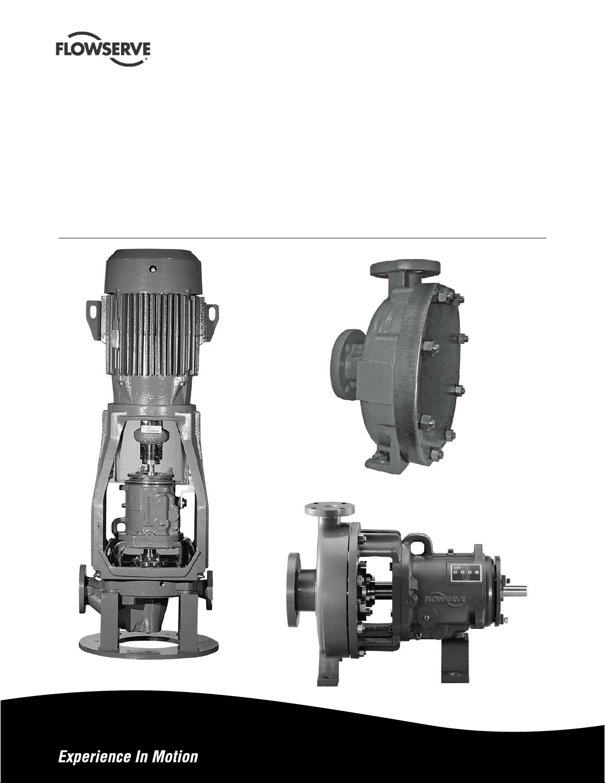
USER INSTRUCTIONS
Casing Blind Covers
Metallic Pumps
ASME (ANSI) Pumps
PCN= 75663450 – 04-10 (E)
Original Instructions
Installation
Operation
Maintenance
Page 2

CONTENTS
CASING BLIND COVER USER INSTRUCTIONS ENGLISH 75663450 04-10
Page
1 INTRODUCTION AND SAFETY ...........................3
1.1 General ........................................................ 3
1.2 CE marking and approvals...........................3
1.3 Disclaimer .................................................... 3
1.4 Copyright...................................................... 3
1.5 Duty conditions ............................................3
1.6 Safety...........................................................4
1.7 Specific machine performance.....................5
2 TRANSPORT AND STORAGE.............................5
2.1 Consignment receipt and unpacking ...........5
2.2 Handling.......................................................5
2.3 Lifting............................................................6
2.4 Storage.........................................................6
2.5 Recycling and end of product life.................6
3 DESCRIPTION......................................................6
3.1 Configurations..............................................6
3.2 Nameplate.................................................... 6
3.3 Performance and operation limits................ 7
4 MAINTENANCE...................................................10
4.1 Maintenance schedule...............................10
4.2 Tools required.............................................10
4.3 Examination of parts..................................10
5 INSTALLATION...................................................11
5.1 Pump Power End Removal........................ 11
5.2 Casing Blind Cover Installation.................. 11
6 REMOVAL...........................................................11
7 PARTS LIST AND DRAWINGS...........................12
8 CERTIFICATION.................................................13
9 OTHER RELEVANT DOCUMENTATION AND
MANUALS..........................................................13
9.1 Supplementary User Instructions...............13
9.2 Change notes.............................................13
9.3 Additional sources of information...............13
Page 2 of 13
Page 3
CASING BLIND COVER USER INSTRUCTIONS ENGLISH 75663450 04-10
1 INTRODUCTION AND SAFETY
1.1 General
These instructions must always be kept
close to the product's operating location or
directly with the product.
Flowserve products are designed, developed and
manufactured with state-of-the-art technologies in
modern facilities. The unit is produced with great
care and commitment to continuous quality control,
utilizing sophisticated quality techniques, and safety
requirements.
Flowserve is committed to continuous quality
improvement and being at your service for any further
information about the product in its installation and
operation or about its support products, repair and
diagnostic services.
These instructions are intended to facilitate
familiarization with the product and its permitted use.
Operating the product in compliance with these
instructions is important to help ensure reliability in
service and avoid risks. The instructions may not
take into account local regulations; ensure such
regulations are observed by all, including those
installing the product. Always coordinate repair
activity with operations personnel, and follow all plant
safety requirements and applicable safety and health
laws/regulations.
These instructions provide information relative to the
Casing Blind Covers only. These instructions must
be used in conjunction with the manuals provided
with the pump.
These instructions must be read prior to
installing, operating, using and maintaining the
equipment in any region worldwide. These
supplemental instructions must be used in
conjunction with the pump user instruction
manual. The equipment must not be put into
service until all the conditions relating to safety
noted in the instructions, have been met.
1.2 CE marking and approvals
It is a legal requirement that machinery and equipment
put into service within certai n regions of t he world sha ll
conform with the applicable CE Marking Directive s
covering Machinery and, where ap plicable, L ow Voltag e
Equipment, Electromagnetic Compatibility (EMC),
Pressure Equipment Directive (PED) and Equipment for
Potentially Explosive Atmospheres (ATEX).
Where applicable, the Directives and any additional
Approvals, cover important safety aspects relating to
machinery and equipment and the satisfactory provision
of technical documents and safety instructions. Where
applicable this document incorporates information
relevant to these Directives and App rovals.
To confirm the Approvals applying and if the product is
CE marked, check the serial number plate markings
and the Certification. (See section 7, Certificatio n.)
1.3 Disclaimer
Information in these User Instructions is believed
to be reliable. In spite of all the efforts of
Flowserve to provide sound and all necessary
information the content of this manual may appear
insufficient and is not guaranteed by Flowserve as
to its completeness or accuracy.
Flowserve manufactures products to exacting
International Quality Management System Standards
as certified and audited by external Quality
Assurance organizations. Genuine parts and
accessories have been designed, tested and
incorporated into the products to help ensure their
continued product quality and performance in use.
As Flowserve cannot test parts and accessories
sourced from other vendors the incorrect
incorporation of such parts and accessories may
adversely affect the performance and safety features
of the products. The failure to properly select, install
or use authorized Flowserve parts and accessories is
considered to be misuse. Damage or failure caused
by misuse is not covered by the Flowserve warranty.
In addition, any modification of Flowserve products or
removal of original components may impair the safety
of these products in their use.
1.4 Copyright
All rights reserved. No part of these instructions may
be reproduced, stored in a retrieval system or
transmitted in any form or by any means without prior
permission of Flowserve.
1.5 Duty conditions
This product has been selected to meet the
specifications of your purchaser order. The
acknowledgement of these conditions has been sent
separately to the Purchaser. A copy should be kept
with these instructions.
Page 3 of 13
Page 4
CASING BLIND COVER USER INSTRUCTIONS ENGLISH 75663450 04-10
The product must not be operated beyond
the parameters specified for the application. If
there is any doubt as to the suitability of the
product for the application intended, contact
Flowserve for advice.
The blind cover has been provided with a
standard gasket material which may not be
appropriate for your service. Please ensure
material compatibility before installation.
Cover plate material compatibility is the
responsibility of the end user.
If the conditions of service on your purchase order are
going to be changed (for ex ample li quid pum ped,
temperature or duty) it is requested that the user seeks
the written agreement of Flowserv e befo re sta rt up.
1.6 Safety
1.6.1 Summary of safety markings
These User Instructions contain specific safety
markings where non-observance of an instruction would
cause hazards. The specific safety markings are:
This sign is not a safety symbol but indicates
an important instructio n in the assembly pro cess.
1.6.2 Personnel qualification and training
All personnel involved in the operation, installation,
inspection and maintenance of the unit must be
qualified to carry out the work involved. If the
personnel in question do not already possess the
necessary knowledge and skill, appropriate training
and instruction must be provided. If required the
operator may commission the manufacturer/supplier
to provide applicable training.
Always coordinate repair activity with operations and
health and safety personnel, and follow all plant
safety requirements and applicable safety and health
laws and regulations.
1.6.3 Safety action
This is a summary of conditions and actions to
help prevent injury to personnel and damage to
the environment and to equipment. For products
used in potentially explosive atmospheres
section 1.6.4 also applies.
This symbol indicates electrical safety
instructions where non-compliance will involve a high
risk to personal safety or the loss of life.
This symbol indicates safety instruct ions where
non-compliance would affect personal safety and
could result in loss of life.
This symbol indicates “hazardous and toxic fluid”
safety instructions where non-compliance would affect
personal safety and could result in loss of life.
This symbol indicates safety
instructions where non-compliance will involve some
risk to safe operation and personal safety and would
damage the equipment or property.
This symbol indicates explosive atmosphere
zone marking according to ATEX. It is used in safety
instructions where non-compliance in the hazardous
area would cause the risk of an explosion.
This symbol is used in safety instructions to
remind not to rub non-metallic surfaces with a dry
cloth; ensure the cloth is damp. It is used in safety
instructions where non-compliance in the hazardous
area would cause the risk of an explosion.
NEVER DO MAINTENANCE WORK
WHEN THE UNIT IS CONNECTED TO POWER
(Lock out.)
DRAIN THE PUMP AND ISOLATE PIPEWORK
BEFORE DISMANTLING THE PUMP
The appropriate safety precautions should be taken
where the pumped liquids are hazardous.
FLUOROELASTOMERS (When fitted.)
When a pump has experienced temperatures over
250 ºC (482 ºF), partial decomposition of
fluoroelastomers (example: Viton) will occur. In this
condition these are extremely dangerous and skin
contact must be avoided.
HANDLING COMPONENTS
Many precision parts have sharp corners and the
wearing of appropriate safety gloves and equipment
is required when handling these components. To lift
heavy pieces above 25 kg (55 lb) use a crane
appropriate for the mass and in accordance with
current local regulations.
NEVER OPERATE THE PUMP WITHOUT THE
COUPLING GUARD AND ALL OTHER SAFETY
DEVICES CORRECTLY INSTALLED
GUARDS MUST NOT BE REMOVED WHILE
THE PUMP IS OPERATIONAL
Page 4 of 13
Page 5
CASING BLIND COVER USER INSTRUCTIONS ENGLISH 75663450 04-10
THERMAL SHOCK
Rapid changes in the temperature of the liquid within
the pump can cause thermal shock, which can result
in damage or breakage of components and should be
avoided.
Refer to the instruction manual provided
with the pump for more information.
1.6.4.1 Maintenance of the centrifugal pump to avoid a hazard
HOT (and cold) PARTS
If hot or freezing components or auxiliary heating
equipment can present a danger to operators and
persons entering the immediate area, actio n must be
taken to avoid accidental contact (suc h as shieldi ng). If
complete protection is not possible, the mach ine access
must be limited to maintenance staff only with cl ear
visual warnings and indicators to those e ntering the
immediate area. Note: bearing housings must not be
insulated and drive motors and bearings may be hot.
If the temperature is greater than 80 °C (176°F) or
below -5 °C (23 °F) in a restricted zone, or
exceeds local regulations, action as above shall
be taken.
HAZARDOUS LIQUIDS
When the pump is handling hazardous liquids care
must be taken to avoid exposure to the liquid by
appropriate pump placement, limiting personnel
access and by operator training. If the liquid is
flammable and/or explosive, strict safety procedures
must be applied.
PREVENT EXCESSIVE EXTERNAL
PIPE LOAD
Do not use pump as a support for piping. Do not
mount expansion joints, unless allowed by Flowserve
in writing, so that their force, due to internal pressure,
acts on the pump flange.
NEVER EXCEED THE MAXIMUM
DESIGN PRESSURE (MDP) AT THE
TEMPERATURE SHOWN ON THE PUMP
NAMEPLATE
See section 3 for pressure versus temperature
ratings based on the material of construction.
1.6.4 Products used in potentially explosive atmospheres
Measures are required to:
Avoid excess temperature
Prevent build up of explosive mixtures
Prevent the generation of sparks
Prevent leakages
Maintain the pump to avoid hazard
CORRECT MAINTENANCE IS REQUIRED TO
AVOID POTENTIAL HAZARDS WHICH GIVE A
RISK OF EXPLOSION
The responsibility for compliance with main tenance
instructions is with the plant operator.
To avoid potential explosion hazards during maintenance,
the tools, cleaning and painting materials used must not
give rise to sparking or adversely affect the ambient
conditions. Where there is a risk from such tools or
materials, maintenance must be conducted in a safe area.
It is recommended that a maintenance plan and schedule
is adopted. (See section 6, Maintenance.)
1.7 Specific machine performance
For performance parameters see section 1.5, Duty
conditions. Where performance data has been
supplied separately to the purchaser these should be
obtained and retained with these User Instructions if
required
.
2 TRANSPORT AND STORAGE
2.1 Consignment receipt and unpacking
Immediately after receipt of the equipment it must be
checked against the delivery/shipping documents for
its completeness and that there has been no damage
in transportation. Any shortage and/or damage must
be reported immediately to Flowserve Pump Division
and must be received within ten days of receipt of the
equipment. Later claims cannot be accepted.
Check any crate, boxes or wrappings for any
accessories or spare parts that may be packed
separately with the equipment or attached to side
walls of the box or equipment.
2.2 Handling
Boxes, crates, pallets or cartons may be unloaded
using fork lift vehicles or slings dependent on their
size and construction.
Page 5 of 13
Page 6

CASING BLIND COVER USER INSTRUCTIONS ENGLISH 75663450 04-10
2.3 Lifting
Pumps and motors often have integral
lifting lugs or eye bolts. These are intended for use in
only lifting the individual piece of equipment.
Do not use eye bolts or cast-in lifting
lugs to lift pump, motor and baseplate assemblies.
Care must be taken to lift components
or assemblies above the center of gravity to prevent
the unit from flipping. This is especially true with
In-Line pumps.
2.3.1 Lifting pump components
Casing Blind Cover [1220]
Insert an eye bolt in the tapped hole as provided.
Use either a sling or hook through the eye bolt.
2.4 Storage
Store the pump in a clean , dry location
away from vibration. Leave flange covers in place to
keep dirt and other foreign material out of pump
casing. The pump may be stored as above for up to
6 months. Consult Flowserve for preservative actions
when a longer storage period is needed.
2.4.1 Short term storage and packaging
Normal packaging is designed to protect the pump
and parts during shipment and for dry, indoor storage
for up to six months or less. The following is an
overview of our normal packaging:
All loose unmounted items are packaged in a
water proof plastic bag and placed under the
coupling guard
The internal surfaces of ferrous casings, covers,
flange faces, and the impeller surface are
sprayed with Cortec VCI-389, or equal
The pump must be stored in a covered, dry
location
2.4.2 Long term storage and packaging
Long term storage is defined as more than six
months, but less than 12 months. The procedure
Flowserve follows for long term storage of pumps is
given below. These procedures are in addition to the
short term procedure.
Each assembly is hermetically (heat) sealed from
the atmosphere by means of tack wrap sheeting
and rubber bushings (mounting holes)
Desiccant bags are placed inside the tack
wrapped packaging
This packaging will provide protection for up to
twelve months from humidity, salt laden air, dust
etc.
2.5 Recycling and end of product life
At the end of the service life of the product or its
parts, the relevant materials and parts should be
recycled or disposed of using an environmentally
acceptable method and in accordance with local
regulations. If the product contains substances that
are harmful to the environment, these should be
removed and disposed of in accordance with current
local regulations. This also includes the liquids
and/or gases that may be used in the "seal system"
or other utilities.
Make sure that hazardous substances are
disposed of safely and that the correct personal
protective equipment is used. The safety
specifications must be in accordance with the current
local regulations at all times.
3 DESCRIPTION
3.1 Configurations
The Casing Blind Covers are designed to replace the
back pull out unit and prevent product leakage during
maintenance.
3.2 Nameplate
Figure 3-1: Nameplate mounted to blind cover
Serial No.
Equipment No.
Purchase Order
Model
Size
MDP
Material
Date DD/MMM/YY
The casing blind cover nameplate, at a minimum will
contain the following information:
Model – Description of pump model and size
MDP - Maximum design pressure at 38˚C(100˚F)
Material – Flowserve Material Code. See section 3.2
Page 6 of 13
Page 7

CASING BLIND COVER USER INSTRUCTIONS ENGLISH 75663450 04-10
3.3 Performance and operation limits
This product has been selected t o meet t he
specification of your purchase order. See section 1. 5.
The following data is included as additional information
to help with your installation. It is typical, and factors
such as liquid being pumped, temperature, material of
construction, and seal type may influence this data. If
required, a definitive statement f or your appl ication can
be obtained from Flowserve.
3.3.1 Alloy cross reference chart
Figure 3-2 is the Alloy cross-reference chart for
Flowserve ASME (ANSI) pumps.
Figure 3-3 is the Alloy cross reference chart for
wrought casing blind covers.
3.3.2 Pressure-temperature ratings
The pressure–temperature (P-T) ratings for blind
covers are shown in figure 3-4. Determine the
appropriate cover “Material Group No.” in Figure 3-2.
Interpolation may be used to find the pressure rating
for a specific temperature.
The following provides pressuretemperature ratings for the blind covers only.
The lowest rating of all parts connected to the
casing must be used. Consult the user
instructions provided with the pump.
Example:
The pressure temperature rating for a Mark 3 GP2
blind cover, 316 construction, with an operating
temperature of 149˚C is found as follows:
a) From Figure 3-2, the correct material group is 2.2
Cover plate material compatibility is
the responsibility of the end user.
b) From Figure 3-4C, the pressure-temperature
rating is 21.5 bar.
Figure 3-2: Casing Blind Cover Alloy cross-reference chart
Flowserve
Material Code
D3041 316 Plate
D3134 Steel Plate A515 Gr. 70 (Gr. 485 - S.I. units) 1.1
Generic
Designation
A240 Type 316 (UNS Designation S31600)
Specifications Material Group No.
Figure 3-3: Casing Cast Alloy cross-reference chart
Flowserve
Material Code
E3020 Ductile iron DCI A395, Gr. 60-40-18 1.0
E3033 High chrome iron CR28 A532 class 3 Cr
E4027 High chrome iron CR29 None Cr
E4028 High chrome iron CR35 None Cr
C3009 Carbon steel DS A216 Gr. WCB 1.1
C3062 304 D2 A744, Gr. CF8 2.1
C3069 304L D2L A744, Gr. CF3 2.1
C3063 316 D4 A744, Gr. CF8M 2.2
C3067 316L D4L A744, Gr. CF3M 2.2
C3107 Duplex Stainless CD4M A995, Gr. CD4MCuN 2.8
C4028 Alloy 20 D20 A744, Gr. CN7M 3.17
C4029 Durcomet 5 DV None 2.2
K3005
K3007
K3008 Nickel DNI A494, Gr. CZ100 3.2
K4007
K4008
E3041
E3042
E4035
D4036 Durco DC8 DC8 None -
H3004 Titanium Ti B367, Gr. C3 Ti
H3005 Titanium-Pd TiP B367, Gr. C8A Ti
H3007 Zirconium Zr B752, Gr. 702C Ti
Duriron, Durichlor 51 and Superchlor are registered trademarks of Flowserve Corporation.
Hastelloy is a registered trademark of Haynes International, Inc.
Inconel and Monel are registered trademarks of International Nickel Co. Inc.
Generic
Designation
Inconel 600
Monel 400
Hastelloy B
Hastelloy C
Duriron
Durichlor 51
Superchlor
Durco Legacy
Codes
DINC A494, Gr. CY40 3.5
DMM A494, Gr. M35-1 3.4
DC2 A494, Gr. N7M 3.7
DC3 A494, Gr. CW6M 3.8
D A518, Gr. 1 No load
D51 A518, Gr. 2 No load
SD51 A518, Gr. 2 No load
ASTM
Specifications
Material
Group No.
2.2
Page 7 of 13
Page 8

CASING BLIND COVER USER INSTRUCTIONS ENGLISH 75663450 04-10
Figure 3-4A Blind Cover Ratings
Durco Mark 3 GP3 Pumps, Durco Mark 2, Durco Mark 2 In-Line, Durco Mark 3 In-Line
Worthington D1000 Pumps
Material Group No.
˚C
-73 24.1 24.1 24.1 17.4 24.1 24.1 24.1 24.1 24.1 24.1
-29 24.1 24.1 24.1 24.1 17.4 24.1 24.1 24.1 24.1 24.1 24.1
-18 24.1 24.1 24.1 24.1 17.4 24.1 24.1 24.1 24.1 24.1 24.1
38 24.1 24.1 24.1 24.1 17.4 24.1 24.1 24.1 24.1 24.1 24.1
93 22.0 20.1 20.8 23.2 17.4 21.3 22.9 24.1 24.1 20.9 21.4
149 21.4 18.1 18.8 21.4 17.4 19.9 21.4 23.5 23.5 18.7 18.7
204 20.7 16.6 17.3 19.8 17.4 19.3 19.9 22.7 22.7 16.9 15.9
260 19.6 15.3 16.1 18.5 17.4 19.1 19.3 21.4 21.4 15.7 13.2
316 17.9 14.6 15.1 17.9 17.4 19.1 19.2 19.5 19.5 14.5 10.5
343 17.4 14.4 14.9 19.1 19.0 19.0 19.0 9.1
371 17.4 14.2 14.4 19.1 18.9 18.3 18.3 7.7
1.1 2.1 2.2 2.8 3.2 3.4 3.5 3.7 3.8 3.17 Ti Temp
bar
Material Group No.
˚F
-100 350 350 350 252 350 350 350 350 350 350
-20 350 350 350 350 252 350 350 350 350 350 350
100 350 350 350 350 252 350 350 350 350 350 350
200 319 292 301 336 252 309 332 350 350 303 310
300 310 263 272 310 252 289 310 341 341 271 271
400 300 241 250 287 252 280 288 329 329 245 231
500 284 222 233 268 252 277 280 310 310 228 191
600 260 211 219 259 252 277 278 282 282 210 152
650 253 209 216 277 276 275 275 132
700 253 207 209 277 274 266 266 112
1.1 2.1 2.2 2.8 3.2 3.4 3.5 3.7 3.8 3.17 Ti Temp
psi
0 350 350 350 350 252 350 350 350 350 350 350
Figure 3-4B Blind Cover Ratings
HOC Pumps
Material Group No.
˚C
-73 25.9 25.9 25.9 18.7 25.9 25.9 25.9 25.9 25.9 25.9
-29 25.9 25.9 25.9 25.9 18.7 25.9 25.9 25.9 25.9 25.9 25.9
-18 25.9 25.9 25.9 25.9 18.7 25.9 25.9 25.9 25.9 25.9 25.9
38 25.9 25.9 25.9 25.9 18.7 25.9 25.9 25.9 25.9 25.9 25.9
93 23.7 21.6 22.4 25.0 18.7 22.9 24.6 25.9 25.9 22.5 23.0
149 23.0 19.5 20.2 23.0 18.7 21.4 23.0 25.3 25.3 20.1 20.1
204 22.3 17.9 18.6 21.3 18.7 20.8 21.4 24.4 24.4 18.2 17.1
260 21.1 16.5 17.3 19.9 18.7 20.6 20.8 23.0 23.0 16.9 14.2
316 19.3 15.7 16.3 19.3 18.7 20.6 20.7 21.0 21.0 15.6 11.3
343 18.7 15.5 16.0 20.6 20.4 20.4 20.4 9.8
371 18.7 15.3 15.5 20.6 20.3 19.7 19.7 8.3
˚F
-100 377 377 377 271 377 377 377 377 377 377
-20 377 377 377 377 271 377 377 377 377 377 377
100 377 377 377 377 271 377 377 377 377 377 377
200 343 314 324 362 271 333 357 377 377 326 334
300 334 283 293 334 271 311 334 367 367 292 292
400 323 259 269 309 271 301 310 354 354 264 249
500 306 239 251 288 271 298 301 334 334 245 206
600 280 227 236 279 271 298 299 303 303 226 164
650 272 225 232 298 297 296 296 142
700 272 223 225 298 295 286 286 121
1.1 2.1 2.2 2.8 3.2 3.4 3.5 3.7 3.8 3.17 Ti Temp
bar
Material Group No.
1.1 2.1 2.2 2.8 3.2 3.4 3.5 3.7 3.8 3.17 Ti Temp
psi
0 377 377 377 377 271 377 377 377 377 377 377
Page 8 of 13
Page 9

CASING BLIND COVER USER INSTRUCTIONS ENGLISH 75663450 04-10
Figure 3-4C Blind Cover Ratings
Durco Mark 3 GP1 and GP2
Material Group No.
˚C
-73 27.6 27.6 27.6 17.4 24.1 24.1 27.6 27.6 24.1 27.6
-29 27.6 27.6 27.6 27.6 17.4 24.1 24.1 27.6 27.6 24.1 27.6
-18 27.6 27.6 27.6 27.6 17.4 24.1 24.1 27.6 27.6 24.1 27.6
38 27.6 27.6 27.6 27.6 17.4 24.1 24.1 27.6 27.6 24.1 27.6
93 25.2 23.0 23.7 26.5 17.4 21.3 22.9 27.6 27.6 20.9 24.5
149 24.4 20.7 21.5 24.5 17.4 19.9 21.4 26.8 26.8 18.7 21.3
204 23.7 19.0 19.7 22.6 17.4 19.3 19.9 25.9 25.9 16.9 18.2
260 22.4 17.5 18.4 21.1 17.4 19.1 19.3 24.5 24.5 15.7 15.1
316 20.5 16.7 17.2 20.4 17.4 19.1 19.2 22.2 22.2 14.5 12.0
343 19.9 16.5 17.0 19.1 19.0 21.7 21.7 10.4
371 19.9 16.3 16.5 19.1 18.9 21.0 21.0 8.8
˚F
-100 400 400 400 252 350 350 400 400 350 400
-20 400 400 400 400 252 350 350 400 400 350 400
100 400 400 400 400 252 350 350 400 400 350 400
200 365 333 344 384 252 309 332 400 400 303 355
300 354 300 311 355 252 289 310 389 389 271 309
400 343 275 286 328 252 280 288 376 376 245 264
500 324 253 267 307 252 277 280 355 355 228 219
600 297 242 250 296 252 277 278 323 323 210 173
650 289 239 247 277 276 315 315 151
700 289 236 239 277 274 304 304 128
1.1 2.1 2.2 2.8 3.2 3.4 3.5 3.7 3.8 3.17 Ti Temp
bar
Material Group No.
1.1 2.1 2.2 2.8 3.2 3.4 3.5 3.7 3.8 3.17 Ti Temp
psi
0 400 400 400 400 252 350 350 400 400 350 400
Figure 3-4D Durco Mark 3 Group2-13” Lo-Flo Pumps with Class 300 Flanges
Material Group No.
˚C
-73 31.0 31.0 31.0 17.4 24.1 27.6 31.0 31.0 24.1 31.0
-29 31.0 31.0 31.0 31.0 31.0 17.4 24.1 27.6 31.0 31.0 24.1 31.0
-18 31.0 31.0 31.0 31.0 31.0 17.4 24.1 27.6 31.0 31.0 24.1 31.0
38 31.0 31.0 31.0 31.0 31.0 17.4 24.1 27.6 31.0 31.0 24.1 31.0
93 29.1 28.3 25.9 26.7 29.8 17.4 21.3 26.1 31.0 31.0 20.9 27.5
149 27.4 27.5 23.3 24.1 27.5 17.4 19.9 24.4 30.2 30.2 18.7 24.0
204 25.5 26.6 21.3 22.2 25.4 17.4 19.3 22.7 29.2 29.2 16.9 20.5
260 24.0 25.2 19.7 20.7 23.8 17.4 19.1 22.1 27.5 27.5 15.7 17.0
316 22.5 23.1 18.7 19.4 23.0 17.4 19.1 21.9 25.0 25.0 14.5 13.4
343 21.8 22.4 18.5 19.2 19.1 21.8 24.4 24.4 11.7
371 22.4 18.3 18.5 19.1 21.6 23.6 23.6 9.9
1.0 1.1 2.1 2.2 2.8 3.2 3.4 3.5 3.7 3.8 3.17 Ti Temp
bar
Material Group No.
˚F
-100 450 450 450 252 350 400 450 450 350 450
-20 450 450 450 450 450 252 350 400 450 450 350 450
100 450 450 450 450 450 252 350 400 450 450 350 450
200 422 410 375 388 432 252 309 379 450 450 303 399
300 397 398 338 350 399 252 289 354 438 438 271 348
400 369 386 309 322 369 252 280 330 423 423 245 297
500 348 365 285 300 345 252 277 320 399 399 228 246
600 327 334 272 281 333 252 277 318 363 363 210 195
650 316 325 269 278 277 316 354 354 170
700 325 266 269 277 313 342 342 144
1.0 1.1 2.1 2.2 2.8 3.2 3.4 3.5 3.7 3.8 3.17 Ti Temp
psi
0 450 450 450 450 450 252 350 400 450 450 350 450
Page 9 of 13
Page 10

CASING BLIND COVER USER INSTRUCTIONS ENGLISH 75663450 04-10
4 MAINTENANCE
It is the plant operator's responsibility to ensure
that all maintenance, inspection and assembly work
is carried out by authorized and qualified personnel
who have adequately familiarized themselves with
the subject matter by studying this manual in detail.
(See also section 1.6.2.)
Any work on the machine must be performed when it
is at a standstill. It is imperative that the procedure
for shutting down the machine is followed.
If platforms, stairs and guard rails are required for
maintenance, they must be placed for easy access to
areas where maintenance and inspection are to be
carried out. The positioning of these accessories
must not limit access or hinder the lifting of the part to
be serviced.
When air or compressed inert gas is used in the
maintenance process, the operator and anyone in the
vicinity must be careful and have the appropriate
protection.
Do not spray air or compressed inert gas on skin.
Do not direct an air or gas jet towards other people.
Never use air or compressed inert gas to clean
clothes.
Before working on the pump, take measures to
prevent the pump from being accidentally started.
Place a warning sign on the starting device:
"Machine under repair: do not start."
With electric drive equipment, lock the main switch
open and withdraw any fuses. Put a warning sign on
the fuse box or main switch:
"Machine under repair: do not connect."
Never clean equipment with flammable solvents or
carbon tetrachloride. Protect yourself against toxic
fumes when using cleaning agents.
Refer to the parts list shown in section 8 for item
number references used throughout this section.
4.1 Maintenance schedule
b) Check that the duty condition is in the safe
operating range for the pump.
4.2 Tools required
A typical range of tools that will be required to
maintain these pumps is listed below.
Standard hand tools SAE
Hand wrenches
Socket wrenches
Allen wrenches
Soft mallet
Screwdrivers
4.3 Examination of parts
Cleaning/inspection
All parts should now be thoroughly cleaned and
inspected. New gaskets should be used. Any parts
that show wear or corrosion should be replaced with
new genuine Flowserve parts.
It is important that only non-flammable,
non-contaminated cleaning fluids are used. These
fluids must comply with plant safety and environmental
guidelines.
It is recommended that a maintenance plan and
schedule be implemented, in accordance with these
User Instructions, to include the following:
a) Check for any leaks from gaskets and seals
Page 10 of 13
Page 11

CASING BLIND COVER USER INSTRUCTIONS ENGLISH 75663450 04-10
5 INSTALLATION
5.1 Pump Power End Removal
Remove the power end according to
the user instruction provided with the pump.
a) Before performing any maintenance, disconnect the
driver from its power supply and lock it off line.
Lock out power to driver to prevent
personal injury.
b) Close the discharge and suction valves, and
drain all liquid from the pump.
c) Close all valves on auxiliary equipment and
piping, then disconnect all auxiliary piping.
d) Decontaminate the pump as necessary.
If Flowserve pumps contain
dangerous chemicals, it is important to follow
plant safety guidelines to avoid personal injury or
death.
e) Remove casing fasteners [6580.1]. On GP1 In-
Line pumps the studs [6572.1] must be removed.
f) Remove the fasteners holding the bearing
housing foot to the baseplate (not applicable on
In-Line pumps).
g) Move the power end, rear cover, and seal chamber
assembly away from the casing. On In-Line pumps
the simplest method of power end removal is to first
remove the motor and motor adapte r with a crane.
However this is often not practical and the power
end must be removed by hand
h) Discard the casing/cover gasket [4590.1].
Lock out power to driver to prevent
personal injury.
b) Close the discharge and suction valves, and
drain all liquid from the pump.
c) Close all valves on auxiliary equipment and
piping, then disconnect all auxiliary piping.
d) Decontaminate the pump as necessary.
If Flowserve pumps contain
dangerous chemicals, it is important to follow
plant safety guidelines to avoid personal injury or
death.
e) Support the cover [1220] with appropriate
equipment.
f) Remove casing fasteners [6580.1]. On GP1 In-
Line pumps the studs [6572.1] must be removed.
g) Move the cover away from the casing.
h) Discard the casing/cover gasket [4590.1].
The cover assembly is heavy. It is
important to follow plant safety guidelines when
lifting it.
The power end and rear cover
assembly is heavy. It is important to follow plant
safety guidelines when lifting it.
5.2 Casing Blind Cover Installation
a) Install a new rear cover gasket [4590.1] between
the blind rear cover [1220] and the casing [1100].
b) Use studs [6572.1] and nuts [6580.1] and torque
to values found in user instructions provided with
the pump.
5.2.1 Pre start-up checks
All fasteners tightened to the correct torque
6 REMOVAL
a) Before performing any maintenance, disconnect the
driver from its power supply and lock it off line.
Page 11 of 13
Page 12

CASING BLIND COVER USER INSTRUCTIONS ENGLISH 75663450 04-10
7 PARTS LIST AND DRAWINGS
Page 12 of 13
Page 13

CASING BLIND COVER USER INSTRUCTIONS ENGLISH 75663450 04-10
8 CERTIFICATION
Certificates, determined from the contract
requirements are provided with these instructions
where applicable. Examples are certificates for CE
marking and ATEX marking etc. If required, copies of
other certificates sent separately to the Purchaser
should be obtained from Purchaser for retention with
these User Instructions.
9 OTHER RELEVANT DOCUMENTATION AND MANUALS
9.1 Supplementary User Instructions
Supplementary instructions such as for a driver,
instrumentation, controller, seals, sealant systems etc
are provided as separate documents in their original
format. If further copies of these are required they
should be obtained from the supplier for retention
with these User Instructions.
9.2 Change notes
If any changes, agreed with Flowserve Pump
Division, are made to the product after it is supplied,
a record of the details should be maintained with
these User Instructions.
9.3 Additional sources of information
The following are excellent sources for additional
information on Flowserve Mark 3 pumps, and
centrifugal pumps in general.
Pump Engineering Manual
R.E. Syska, J.R. Birk,
Flowserve Corporation, Dayton, Ohio, 1980.
Specification for Horizontal End Suction Centrifugal
Pumps for Chemical Process, ASME B73.1M
The American Society of Mechanical Engineers,
New York, NY.
Specification for Vertical In-Line Centrifugal Pumps
for Chemical Process, ASME B73.2M
The American Society of Mechanical Engineers,
New York, NY.
BLANK
American National Standard for Centrifugal Pumps
for Nomenclature, Definitions, Design and Application
(ANSI/HI 1.1-1.3)
Hydraulic Institute, 9 Sylvan Way, Parsippany,
New Jersey 07054-3802.
American National Standard for Vertical Pumps for
Nomenclature, Definitions, Design and Application
(ANSI/HI 2.1-2.3)
Hydraulic Institute, 9 Sylvan Way, Parsippany,
New Jersey 07054-3802.
American National Standard for Centrifugal Pumps for
Installation, Operation, and Maintenance (ANSI/HI 1.4)
Hydraulic Institute, 9 Sylvan Way, Parsippany,
New Jersey 07054-3802.
Flowserve Durco Pump Parts Catalog.
Flowserve Mark 3 Sales Bulletin.
Flowserve Mark 3 Technical Bulletin (P-10-501).
RESP73H Application of ASME B73.1M-1991,
Specification for Horizontal End Suction Centrifugal
Pumps for Chemical Process, Process Industries
Practices
Construction Industry Institute, The University of
Texas at Austin, 3208 Red River Street, Suite 300,
Austin, Texas 78705.
Pump Handbook
2nd edition, Igor J. Karassik et al, McGraw-Hill, Inc.,
New York, NY, 1986.
Centrifugal Pump Sourcebook
John W. Dufour and William E. Nelson,
McGraw-Hill, Inc., New York, NY, 1993.
Pumping Manual, 9th edition
T.C. Dickenson, Elsevier Advanced Technology,
Kidlington, United Kingdom, 1995.
Page 13 of 13
Page 14

CASING BLIND COVER USER INSTRUCTIONS ENGLISH 75663450 04-10
Your Flowserve factory contacts:
Flowserve Pump Division
3900 Cook Boulevard
Chesapeake, VA 23323-1626 USA
Telephone +1 757 485 8000
Fax +1 757 485 8149
Flowserve Pumps Limited
PO Box 17, Newark, Notts NG 24 3BU
United Kingdom
Telephone (24 hours) +44 (0)1636 494 600
Sales & Admin Fax +44 (0)1636 705 991
Repair & Service Fax +44 (0)1636 494 833
E-mail inewark@flowserve.com
Your local Flowserve representative:
To find your local Flowserve representative please
use the Sales Support Locator System found at
www.flowserve.com
FLOWSERVE REGIONAL
SALES OFFICES:
USA and Canada
Flowserve Corporation
Pump
5215 North O’Connor Blvd.,
Suite 2300
Irving, Texas 75039-5421 USA
Telephone 1 972 443 6500
Fax 1 972 443 6800
Europe, Middle East,
Africa
Worthing S.P.A.
Flowserve Corporation
Via Rossini 90/92
20033 Desio (Milan) Italy
Telephone 39 0362 6121
Fax 39 0362 303396
Latin America and
Caribbean
Flowserve Corporation
Pump
6840 Wynnwood Lane
Houston, Texas 77008 USA
Telephone 1 713 803 4434
Fax 1 713 803 4497
Asia Pacific
Flowserve Pte. Ltd
10 Tuas Loop
Singapore 637345
Telephone 65 6771 1600
Fax 65 6779 4607
 Loading...